Power module
Baxter , et al. J
U.S. patent number D837,147 [Application Number D/589,815] was granted by the patent office on 2019-01-01 for power module. This patent grant is currently assigned to CHARGEPOINT, INC.. The grantee listed for this patent is ChargePoint, Inc.. Invention is credited to David Baxter, Darren Chin-Ho Kim, Peter H. Muller, Pasquale Romano, Price B. Terzis.


View All Diagrams
| United States Patent | D837,147 |
| Baxter , et al. | January 1, 2019 |
Power module
Claims
CLAIM The ornamental design for a power module, as shown and described.
| Inventors: | Baxter; David (Monte Sereno, CA), Chin-Ho Kim; Darren (Oakland, CA), Muller; Peter H. (Portland, OR), Romano; Pasquale (Los Gatos, CA), Terzis; Price B. (Los Altos Hills, CA) | ||||||||||
|---|---|---|---|---|---|---|---|---|---|---|---|
| Applicant: |
|
||||||||||
| Assignee: | CHARGEPOINT, INC. (Campbell,
CA) |
||||||||||
| Appl. No.: | D/589,815 | ||||||||||
| Filed: | January 4, 2017 |
| Current U.S. Class: | D13/108; D13/103 |
| Current International Class: | 1302 |
| Field of Search: | ;D13/102-110,118-119,184,199 ;D14/356,432 |
References Cited [Referenced By]
U.S. Patent Documents
| D483725 | December 2003 | Thompson |
| D566650 | April 2008 | McGowan |
| D632643 | February 2011 | Tanaka |
| D638787 | May 2011 | Tanaka |
| D659694 | May 2012 | Sumita |
| D682206 | May 2013 | Farris-Gilbert |
| D686981 | July 2013 | Koyabu |
| D760164 | June 2016 | Aida |
| D785563 | May 2017 | Yang |
| D786191 | May 2017 | McSweyn |
| D803151 | November 2017 | Zhou |
| D810021 | February 2018 | Iwai |
| 2018/0029497 | February 2018 | Shieh |
Assistant Examiner: Buckner; Nathaniel D.
Attorney, Agent or Firm: Nicholson De Vos Webster & Elliott LLP
Description
FIG. 1 shows a front perspective view of a power module showing our new design in an open configuration;
FIG. 2 shows a front view of the power module of FIG. 1;
FIG. 3 shows a back view of the power module of FIG. 1;
FIG. 4 shows a right view of the power module of FIG. 1;
FIG. 5 shows a left view of the power module of FIG. 1;
FIG. 6 shows a top view of the power module of FIG. 1;
FIG. 7 shows a bottom view of the power module of FIG. 1;
FIG. 8 shows a rear perspective view of the power module of FIG. 1;
FIG. 9 is a front perspective view of the power module of FIG. 1, shown in a closed position;
FIG. 10 shows a front view of the power module of FIG. 9;
FIG. 11 shows a back view of the power module of FIG. 9;
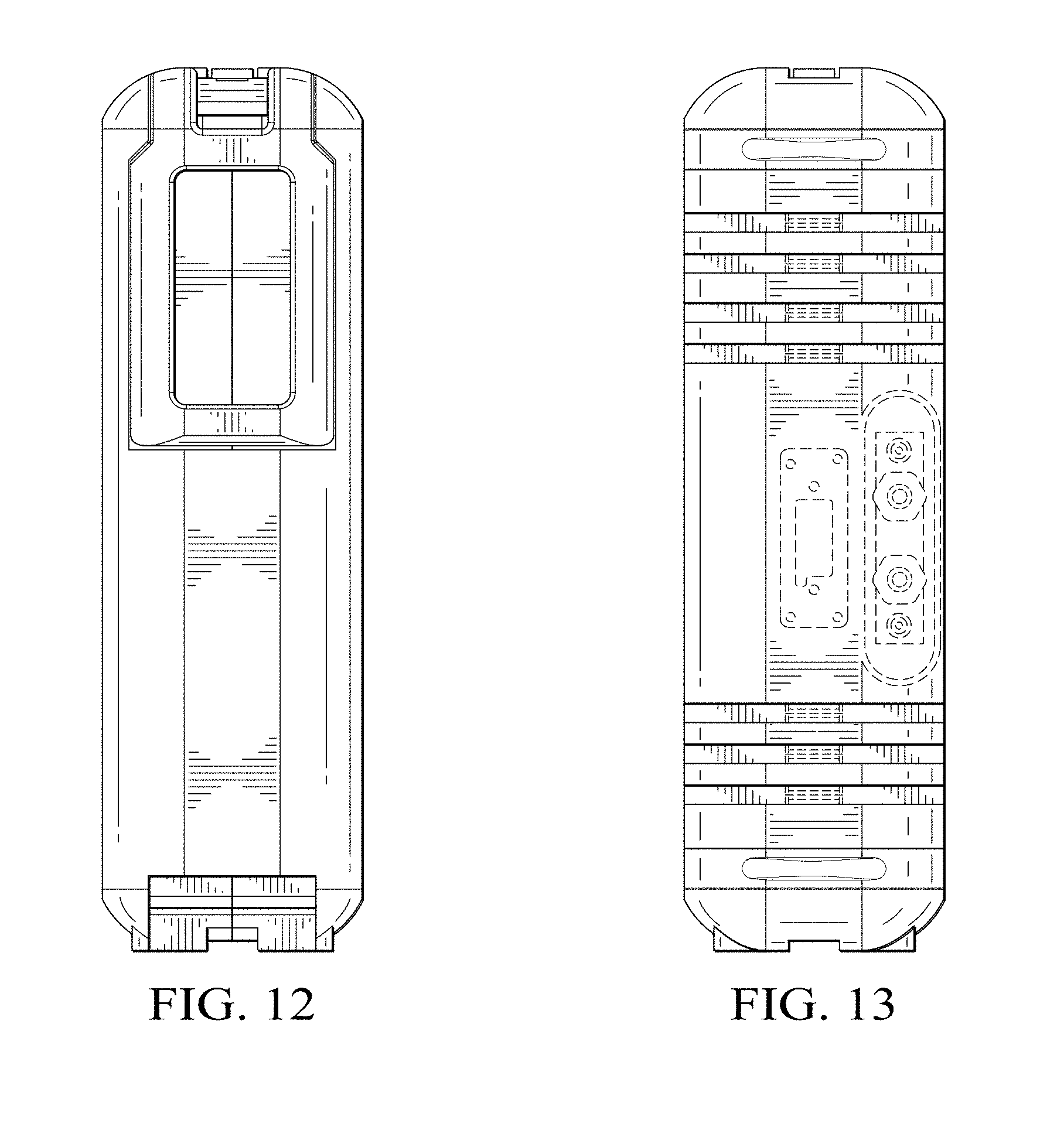
FIG. 12 shows a right view of the power module of FIG. 9;
FIG. 13 shows a left view of the power module of FIG. 9;
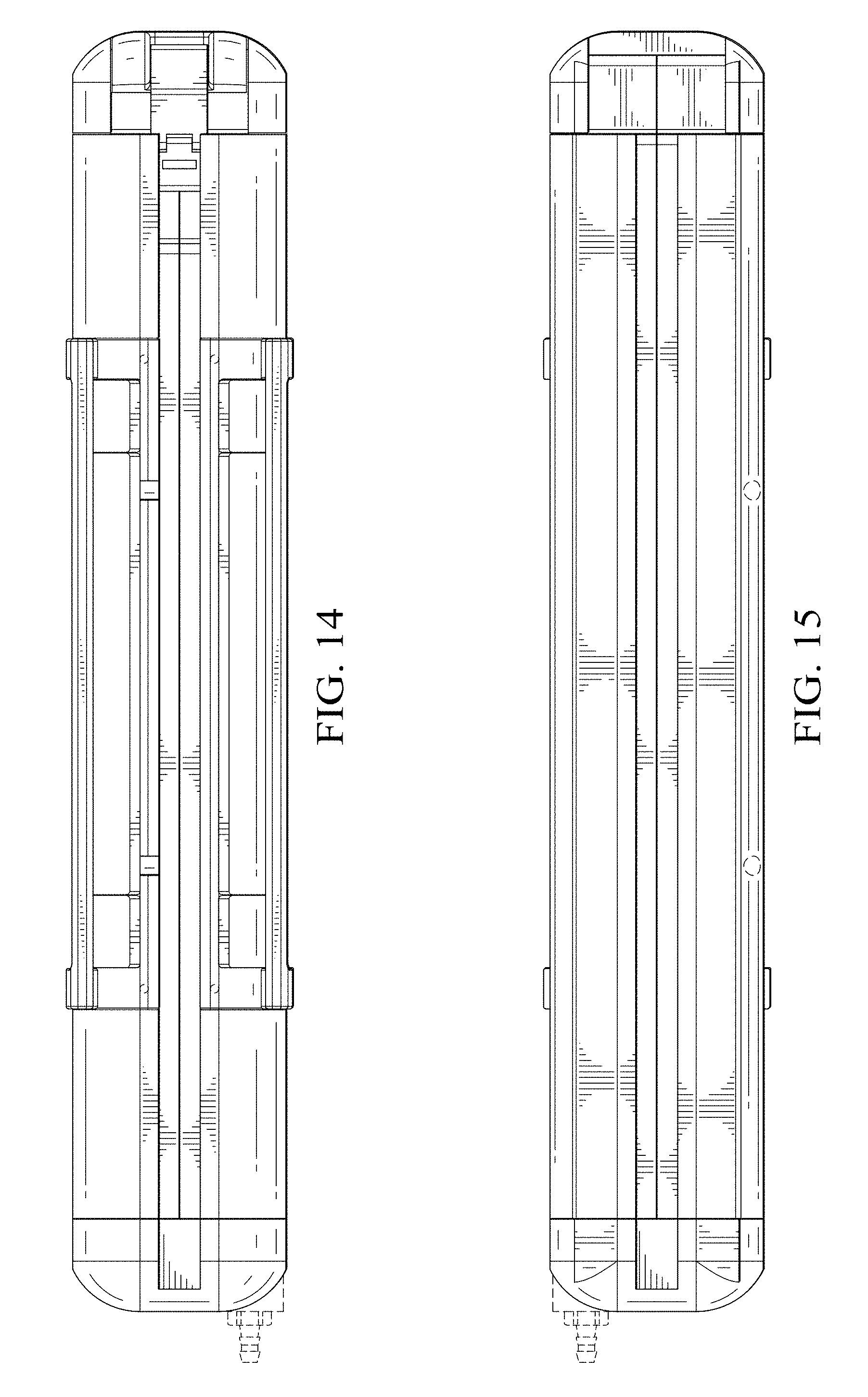
FIG. 14 shows a top view of the power module of FIG. 9;
FIG. 15 shows a bottom view of the power module of FIG. 9; and,
FIG. 16 shows a rear perspective view of the power module of FIG. 9.
The broken lines illustrate environmental structure and form no part of the claimed design.
* * * * *
D00000
D00001
D00002
D00003
D00004
D00005
D00006
D00007
D00008
D00009
D00010
D00011
D00012

XML
uspto.report is an independent third-party trademark research tool that is not affiliated, endorsed, or sponsored by the United States Patent and Trademark Office (USPTO) or any other governmental organization. The information provided by uspto.report is based on publicly available data at the time of writing and is intended for informational purposes only.
While we strive to provide accurate and up-to-date information, we do not guarantee the accuracy, completeness, reliability, or suitability of the information displayed on this site. The use of this site is at your own risk. Any reliance you place on such information is therefore strictly at your own risk.
All official trademark data, including owner information, should be verified by visiting the official USPTO website at www.uspto.gov. This site is not intended to replace professional legal advice and should not be used as a substitute for consulting with a legal professional who is knowledgeable about trademark law.