Catheter tray assembly
Angel , et al. December 30, 2
U.S. patent number D720,471 [Application Number D/441,647] was granted by the patent office on 2014-12-30 for catheter tray assembly. This patent grant is currently assigned to Bio2 Medical, Inc.. The grantee listed for this patent is Bio2 Medical, Inc.. Invention is credited to Luis F. Angel, Bradley Cunningham, Thomas Mullen.


| United States Patent | D720,471 |
| Angel , et al. | December 30, 2014 |
Catheter tray assembly
Claims
CLAIM The ornamental design for a catheter tray assembly, as shown and described.
| Inventors: | Angel; Luis F. (San Antonio, TX), Cunningham; Bradley (Denver, CO), Mullen; Thomas (Littleton, CO) | ||||||||||
|---|---|---|---|---|---|---|---|---|---|---|---|
| Applicant: |
|
||||||||||
| Assignee: | Bio2 Medical, Inc. (Golden,
CO) |
||||||||||
| Appl. No.: | D/441,647 | ||||||||||
| Filed: | January 8, 2013 |
| Current U.S. Class: | D24/229 |
| Current International Class: | 2402 |
| Field of Search: | ;D24/127,130,112-113,186,133 ;606/181,185 ;604/533,534,284,115,19,48,164.01-164.09 ;600/226,372-374,585,114 ;128/200.24,207.14,207.15 |
References Cited [Referenced By]
U.S. Patent Documents
| 6068121 | May 2000 | McGlinch |
| D471641 | March 2003 | McMichael et al. |
| D480816 | October 2003 | McMichael et al. |
| 7401703 | July 2008 | McMichael et al. |
| D609819 | February 2010 | Tomes et al. |
| D650912 | December 2011 | Tomes et al. |
| 8584849 | November 2013 | McCaffrey |
| 8678190 | March 2014 | Tomes et al. |
Attorney, Agent or Firm: Rosenbaum; David G. Rosenbaum IP, P.C.
Description
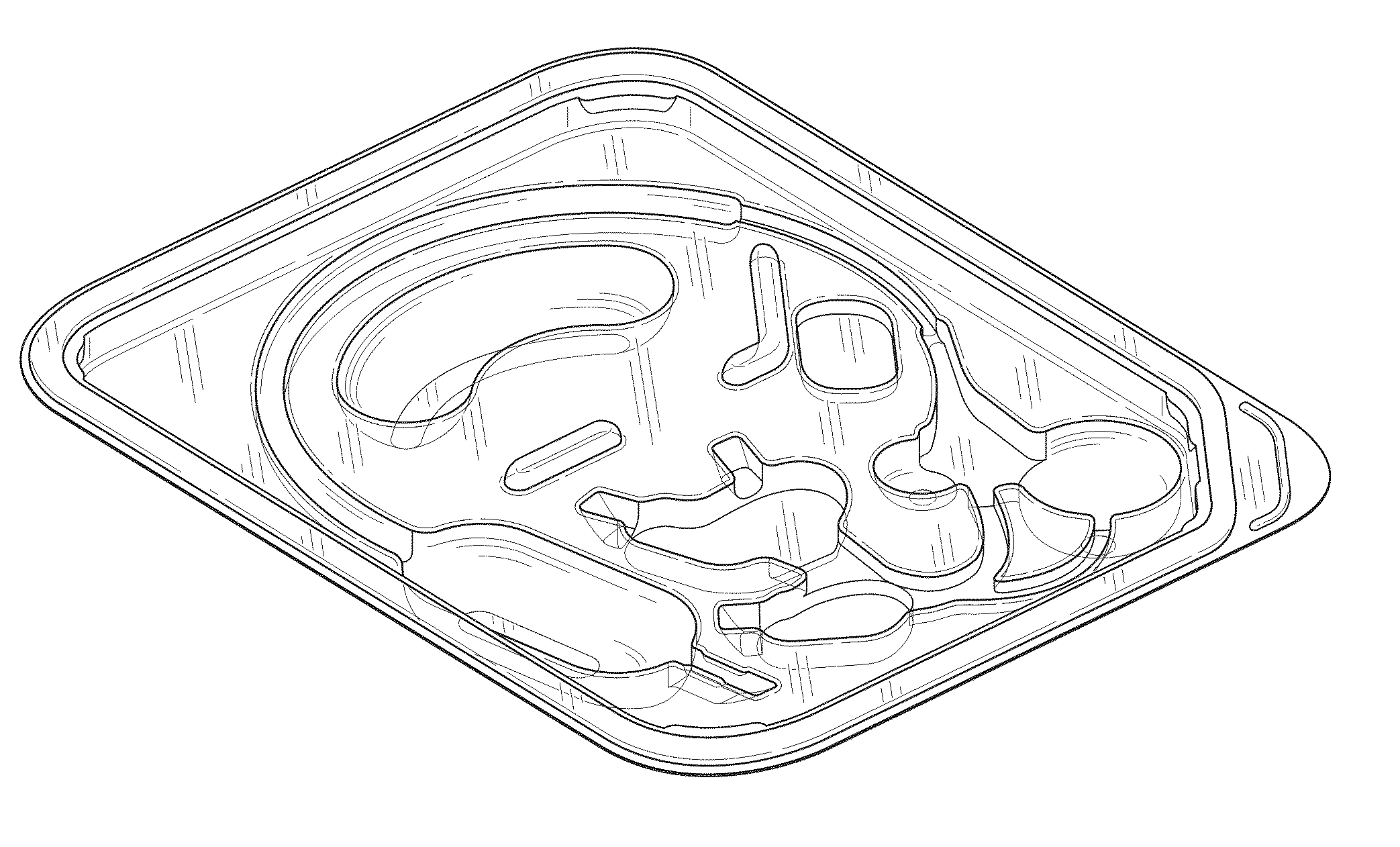
FIG. 1 is a perspective view bottom tray component of the inventive design of a catheter tray assembly in accordance with design of the present invention;
FIG. 2 is first side elevational view thereof;
FIG. 3 is second side elevational view thereof;
FIG. 4 is a first end elevational view thereof;
FIG. 5 is second elevational view thereof;
FIG. 6 is a top plan view of the bottom component of the catheter tray design;
FIG. 7 is a bottom plan view of the bottom component of the catheter tray design;
FIG. 8 is a perspective view of the top component of the catheter tray design;
FIG. 9 is a first side elevational view thereof;
FIG. 10 is a second side elevational view thereof;
FIG. 11 is a first end elevational view thereof;
FIG. 12 is a second end elevational view thereof;
FIG. 13 is a top plan view thereof;
FIG. 14 is a bottom plan view thereof;
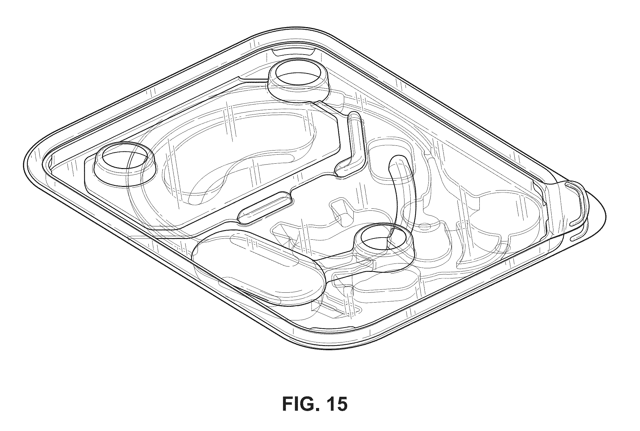
FIG. 15 is a perspective view of the catheter tray assembly in accordance with the design of the present invention, illustrating cooperation between the top tray component and the bottom tray component.
FIG. 16 is a first side elevational view thereof;
FIG. 17 is a second side elevational view thereof;
FIG. 18 is a first end elevational view thereof;
FIG. 19 is a second end elevational view thereof;
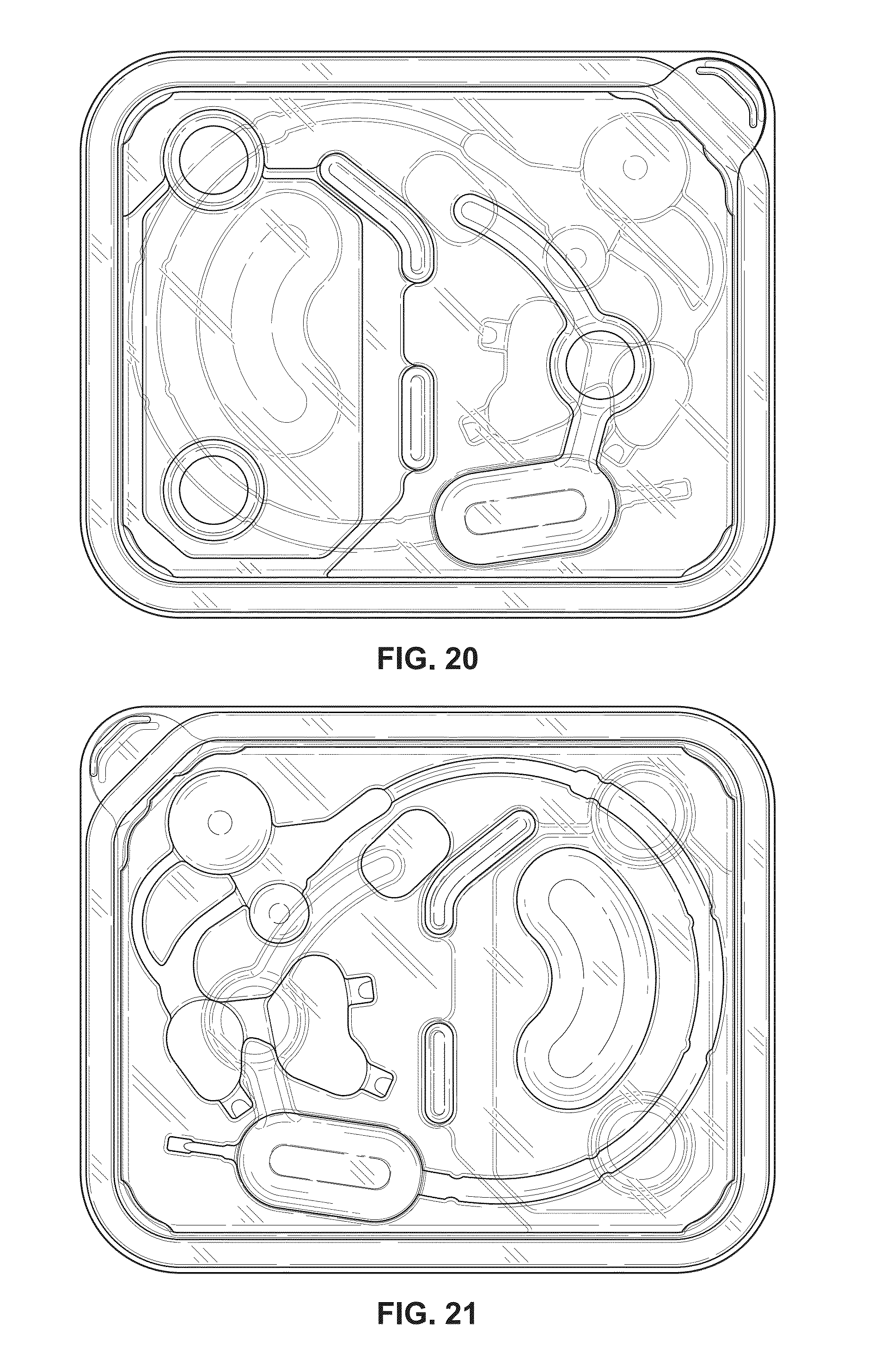
FIG. 20 is a top plan view thereof; and,
FIG. 21 is a bottom plan view thereof.
* * * * *
D00000
D00001
D00002
D00003
D00004
D00005
D00006
D00007
D00008
D00009
XML
uspto.report is an independent third-party trademark research tool that is not affiliated, endorsed, or sponsored by the United States Patent and Trademark Office (USPTO) or any other governmental organization. The information provided by uspto.report is based on publicly available data at the time of writing and is intended for informational purposes only.
While we strive to provide accurate and up-to-date information, we do not guarantee the accuracy, completeness, reliability, or suitability of the information displayed on this site. The use of this site is at your own risk. Any reliance you place on such information is therefore strictly at your own risk.
All official trademark data, including owner information, should be verified by visiting the official USPTO website at www.uspto.gov. This site is not intended to replace professional legal advice and should not be used as a substitute for consulting with a legal professional who is knowledgeable about trademark law.