Hammer toe correcting apparatus
Faux , et al. December 30, 2
U.S. patent number D720,459 [Application Number D/465,004] was granted by the patent office on 2014-12-30 for hammer toe correcting apparatus. This patent grant is currently assigned to FootMind, Inc.. The grantee listed for this patent is FootMind, Inc.. Invention is credited to Jonathan Robert Faux, Chris Robert Hughes.
| United States Patent | D720,459 |
| Faux , et al. | December 30, 2014 |
Hammer toe correcting apparatus
Claims
CLAIM The ornamental design for hammer toe correcting apparatus, as shown and described.
| Inventors: | Faux; Jonathan Robert (Provo, UT), Hughes; Chris Robert (Alpine, UT) | ||||||||||
|---|---|---|---|---|---|---|---|---|---|---|---|
| Applicant: |
|
||||||||||
| Assignee: | FootMind, Inc. (Alpine,
UT) |
||||||||||
| Appl. No.: | D/465,004 | ||||||||||
| Filed: | August 22, 2013 |
| Current U.S. Class: | D24/171 |
| Current International Class: | 2400 |
| Field of Search: | ;D24/171,170,143,144,176,221,231,213,212,226,192,146-149,153,154 ;D15/139 ;128/882 ;7/170 ;83/873,875,86,120 ;601/22,27-29,32,39,104 ;606/53,59,320,321,324,327,328,329 |
References Cited [Referenced By]
U.S. Patent Documents
| D400547 | November 1998 | Albrektsson et al. |
| D420445 | February 2000 | Von Weissenfluh et al. |
| D507649 | July 2005 | Padain |
| D634343 | March 2011 | Burke, III |
Assistant Examiner: Shields; Rhea
Attorney, Agent or Firm: Dhurham Jones & Pinegar Intellectual Property Law Group
Description
FIG. 1 is frontal perspective view of an embodiment of elements of an hammer toe correcting apparatus, including a first element for forming a male member of a joint and a second element for forming a female member of the joint;
FIG. 2 is a first side view of the hammer toe correcting apparatus of FIG. 1;
FIG. 3 is a bottom view of the hammer toe correcting apparatus of FIG. 1;
FIG. 4 is a second side view of the hammer toe correcting apparatus of FIG. 1;
FIG. 5 is a top view of the hammer toe correcting apparatus of FIG. 1;
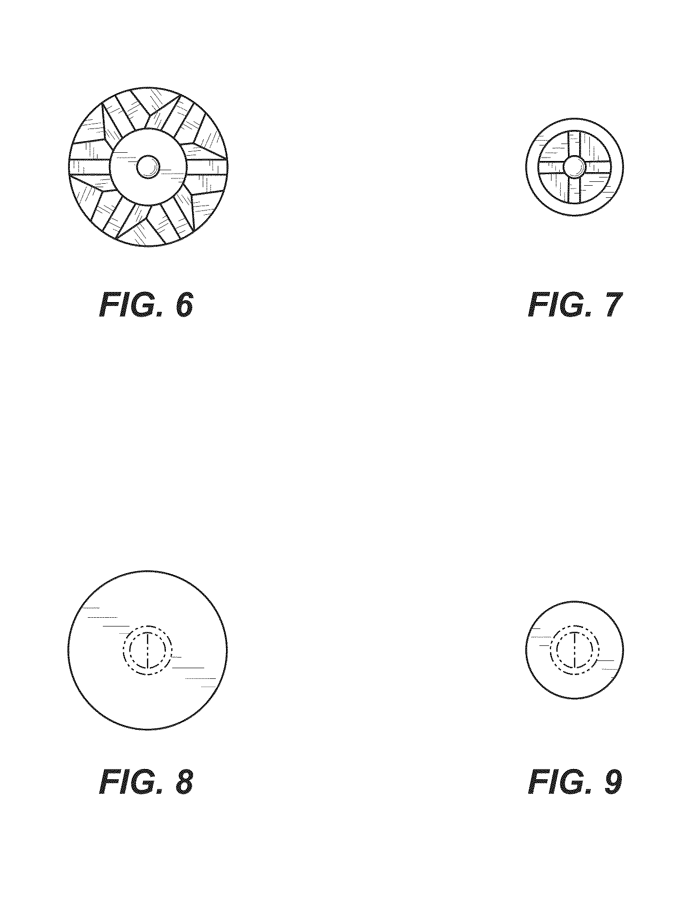
FIG. 6 is a cutting end view of the first element of the hammer toe correcting apparatus of FIG. 1;
FIG. 7 is a cutting end view of the second element of the hammer toe correcting apparatus of FIG. 1;
FIG. 8 is a coupling end view of the first element of the hammer toe correcting apparatus of FIG. 1; and,
FIG. 9 is a coupling end view of the second element of the hammer toe correcting apparatus of FIG. 1.
In the drawings, the broken lines depict unclaimed environment only and form no part of the claimed design.
* * * * *
D00000
D00001
D00002
D00003
D00004
XML
uspto.report is an independent third-party trademark research tool that is not affiliated, endorsed, or sponsored by the United States Patent and Trademark Office (USPTO) or any other governmental organization. The information provided by uspto.report is based on publicly available data at the time of writing and is intended for informational purposes only.
While we strive to provide accurate and up-to-date information, we do not guarantee the accuracy, completeness, reliability, or suitability of the information displayed on this site. The use of this site is at your own risk. Any reliance you place on such information is therefore strictly at your own risk.
All official trademark data, including owner information, should be verified by visiting the official USPTO website at www.uspto.gov. This site is not intended to replace professional legal advice and should not be used as a substitute for consulting with a legal professional who is knowledgeable about trademark law.