Touch sensor film
Nakamura December 30, 2
U.S. patent number D720,353 [Application Number D/498,753] was granted by the patent office on 2014-12-30 for touch sensor film. This patent grant is currently assigned to FUJIFILM Corporation. The grantee listed for this patent is FUJIFILM Corporation. Invention is credited to Samito Nakamura.
| United States Patent | D720,353 |
| Nakamura | December 30, 2014 |
Touch sensor film
Claims
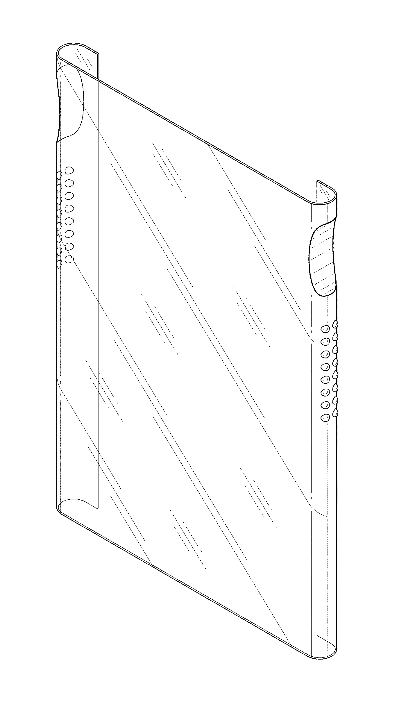
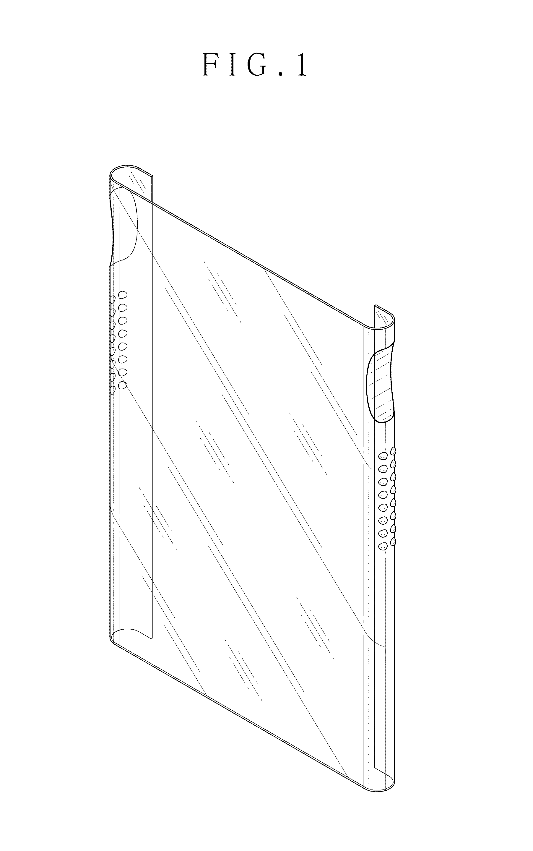
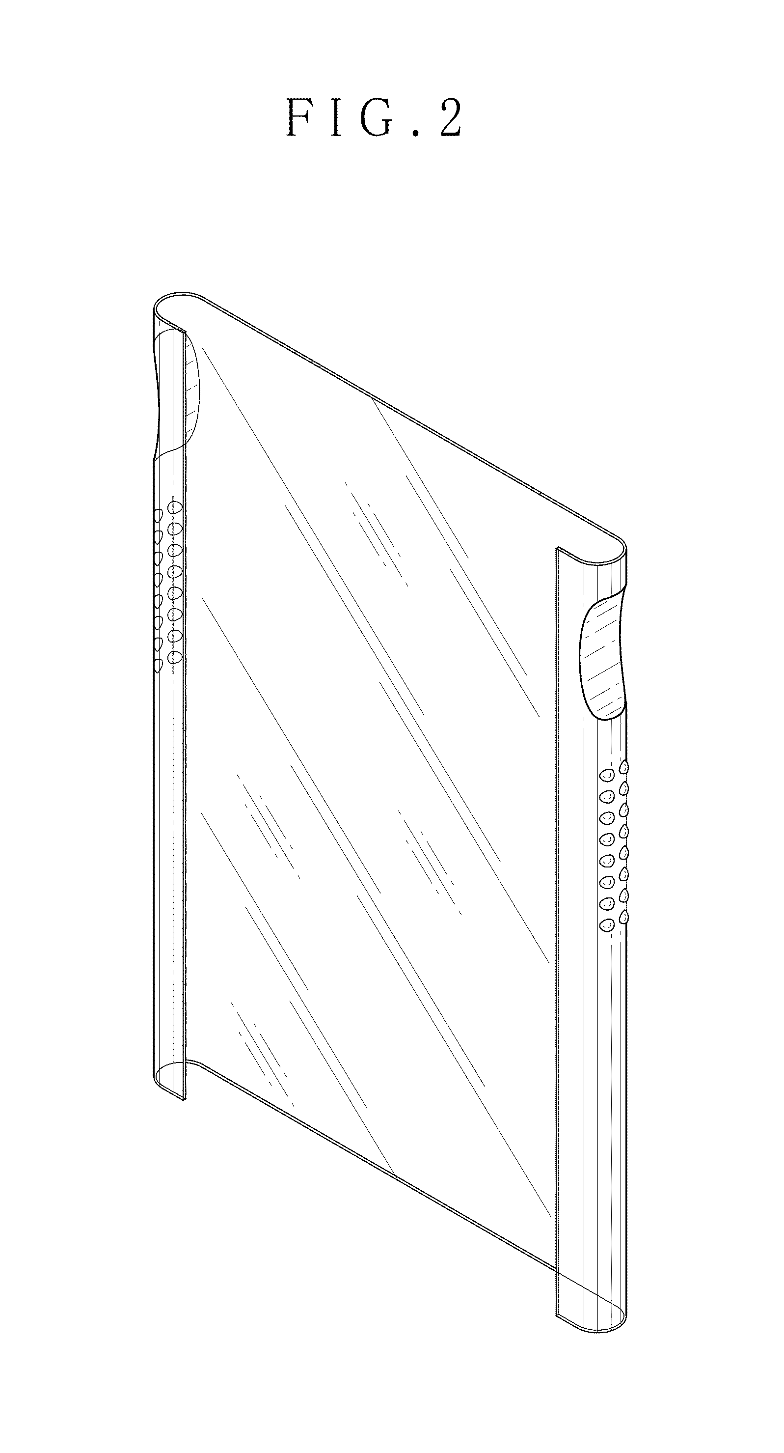
CLAIM The ornamental design for the touch sensor film, as shown and described.
| Inventors: | Nakamura; Samito (Minato-ku, JP) | ||||||||||
|---|---|---|---|---|---|---|---|---|---|---|---|
| Applicant: |
|
||||||||||
| Assignee: | FUJIFILM Corporation (Tokyo,
JP) |
||||||||||
| Appl. No.: | D/498,753 | ||||||||||
| Filed: | August 7, 2014 |
Foreign Application Priority Data
| Feb 19, 2014 [JP] | 2014-003380 | |||
| Current U.S. Class: | D14/432 |
| Current International Class: | 1402 |
| Field of Search: | ;D14/316-319,432-439,442,451-454,496,495,391,385,367,356 ;D8/331,330 ;D18/50,4.6,4.5 ;439/630,635,639,160 ;360/2 ;235/492,486,479,380 |
References Cited [Referenced By]
U.S. Patent Documents
| D665809 | August 2012 | Wang et al. |
| D673958 | January 2013 | Fathollahi |
| D675210 | January 2013 | Kim |
| D678259 | March 2013 | Moore et al. |
| D683700 | June 2013 | Ferrari et al. |
| D690703 | October 2013 | Welch et al. |
| D694240 | November 2013 | Cho |
| D694241 | November 2013 | Cho |
| D694242 | November 2013 | Cho |
| D702239 | April 2014 | Lee et al. |
| D704712 | May 2014 | Sugino et al. |
Attorney, Agent or Firm: Sughrue Mion, PLLC
Description
FIG. 1 is a top, front and right side perspective view of a touch sensor film showing my new design;
FIG. 2 is a top, rear and left side perspective view thereof;
FIG. 3 is a front elevational view thereof;
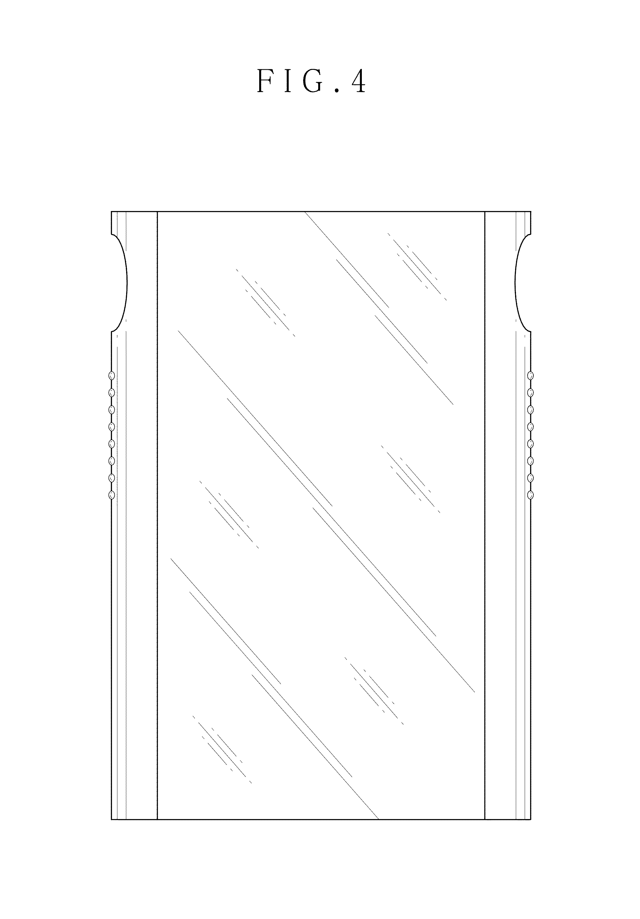
FIG. 4 is a rear elevational view thereof;
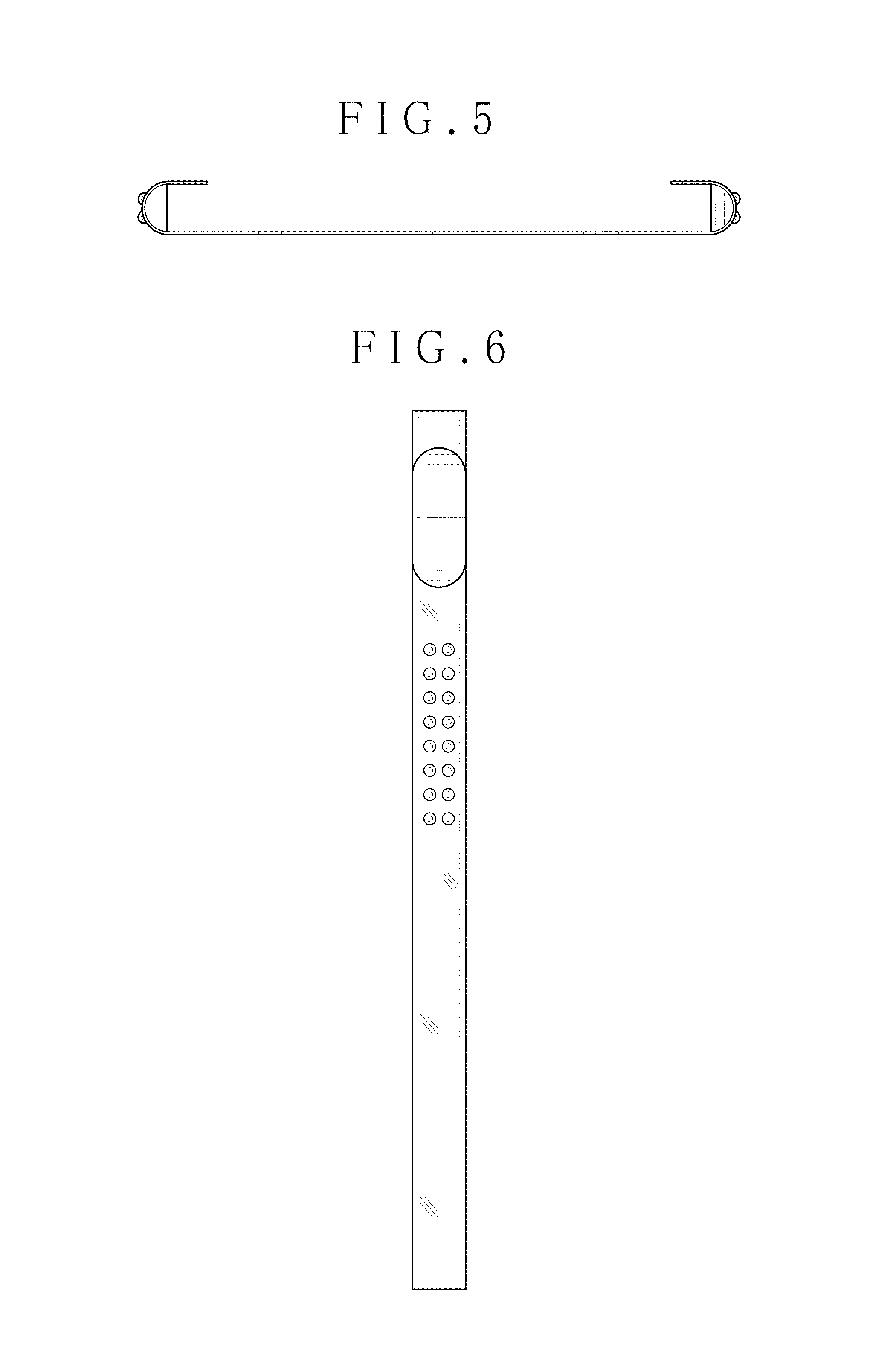
FIG. 5 is a top plan view thereof;
FIG. 6 is a left side elevational view thereof;
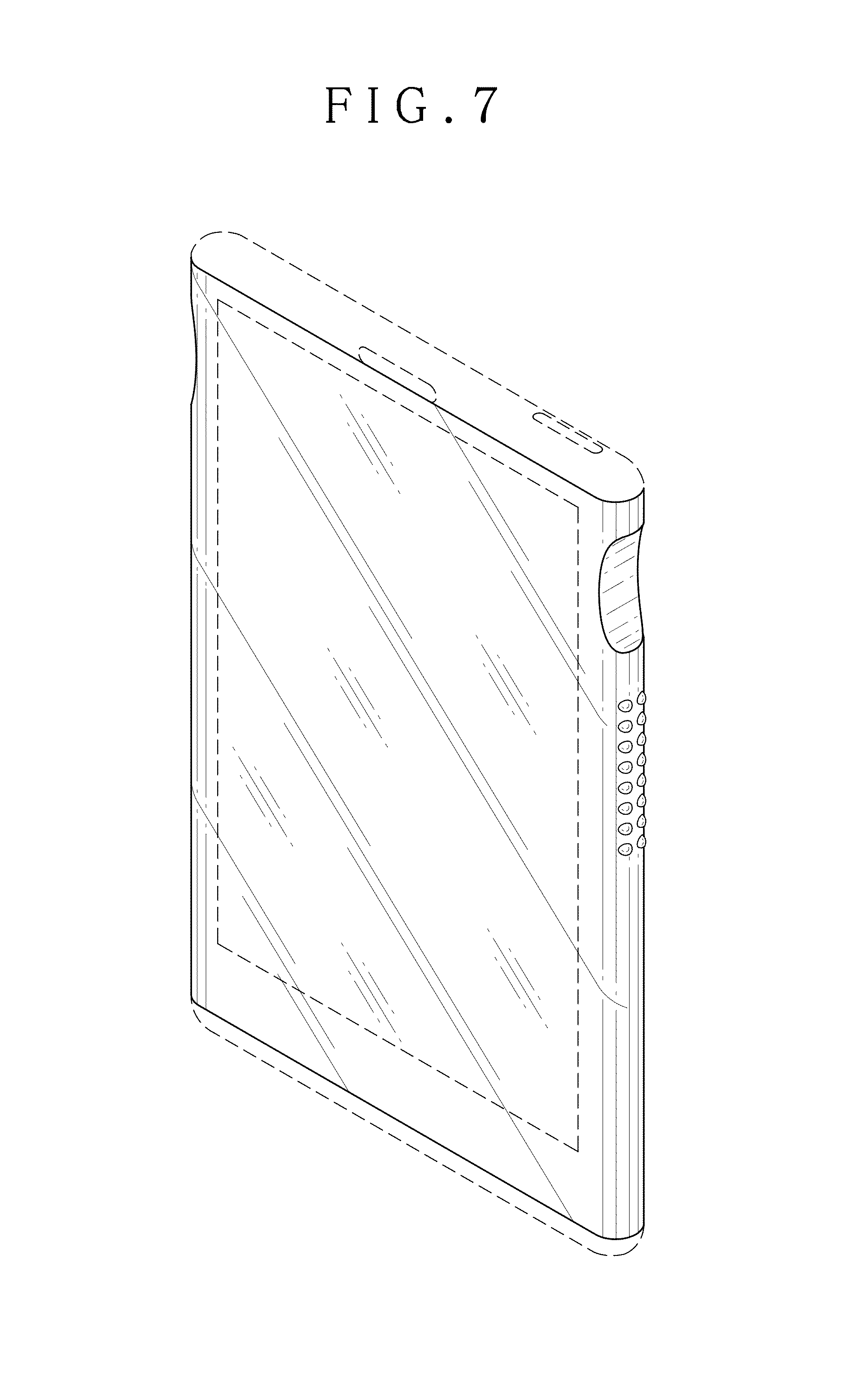
FIG. 7 is a top, front and right side perspective view thereof in a state of being attached to a personal digital assistance; and,
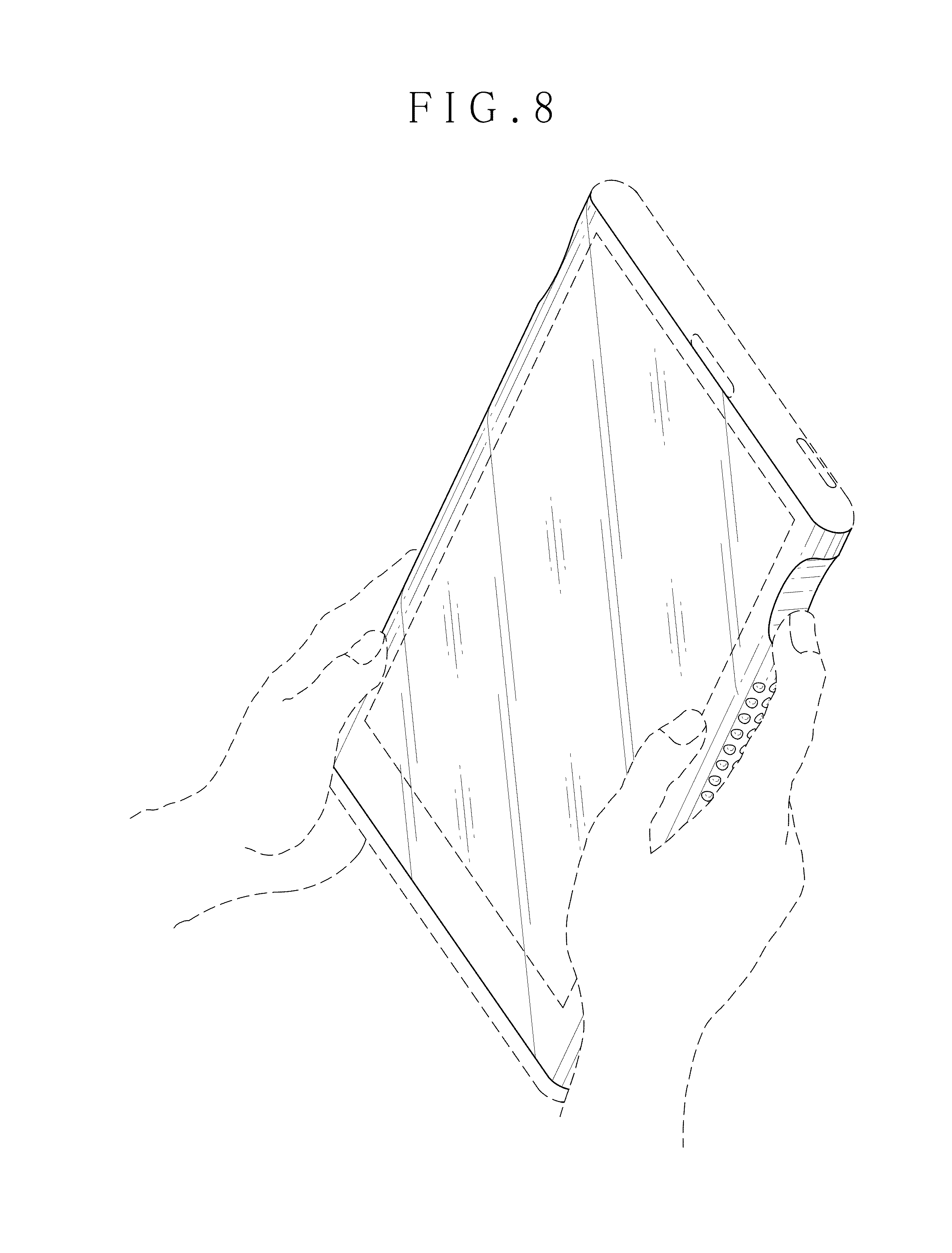
FIG. 8 is a top, front and right side perspective view of the personal digital assistance of FIG. 7 in an operated state.
The broken lines showing the portions of the personal digital assistance in all views are for illustrative purposes only and form no part of the claimed design.
* * * * *
D00000
D00001
D00002
D00003
D00004
D00005
D00006
D00007
XML
uspto.report is an independent third-party trademark research tool that is not affiliated, endorsed, or sponsored by the United States Patent and Trademark Office (USPTO) or any other governmental organization. The information provided by uspto.report is based on publicly available data at the time of writing and is intended for informational purposes only.
While we strive to provide accurate and up-to-date information, we do not guarantee the accuracy, completeness, reliability, or suitability of the information displayed on this site. The use of this site is at your own risk. Any reliance you place on such information is therefore strictly at your own risk.
All official trademark data, including owner information, should be verified by visiting the official USPTO website at www.uspto.gov. This site is not intended to replace professional legal advice and should not be used as a substitute for consulting with a legal professional who is knowledgeable about trademark law.