Wireless emitter
Ervin , et al. December 30, 2
U.S. patent number D720,336 [Application Number D/447,734] was granted by the patent office on 2014-12-30 for wireless emitter. This patent grant is currently assigned to QUALCOMM Incorporated. The grantee listed for this patent is QUALCOMM Incorporated. Invention is credited to David M Bahnemann, Daniel R Ervin, Jatupum Jenwatanavet, Steven J Lundgren, Jeffrey J Vaccaro, Leif A Woodahl.

| United States Patent | D720,336 |
| Ervin , et al. | December 30, 2014 |
Wireless emitter
Claims
CLAIM The ornamental design for a wireless emitter, as shown and described.
| Inventors: | Ervin; Daniel R (Oceanside, CA), Woodahl; Leif A (Poway, CA), Lundgren; Steven J (Ramona, CA), Bahnemann; David M (San Diego, CA), Vaccaro; Jeffrey J (Encinitas, CA), Jenwatanavet; Jatupum (San Diego, CA) | ||||||||||
|---|---|---|---|---|---|---|---|---|---|---|---|
| Applicant: |
|
||||||||||
| Assignee: | QUALCOMM Incorporated (San
Diego, CA) |
||||||||||
| Appl. No.: | D/447,734 | ||||||||||
| Filed: | March 6, 2013 |
| Current U.S. Class: | D14/240 |
| Current International Class: | 1403 |
| Field of Search: | ;D14/242,240,435.1,357,358,140-140.9,155,137,139,243,348,349,351,354,355,138AD ;D10/104.1,104.2 ;375/222 |
References Cited [Referenced By]
U.S. Patent Documents
| D368260 | March 1996 | Oschmann et al. |
| D375097 | October 1996 | Kovens |
| D391953 | March 1998 | Copeland et al. |
| D442156 | May 2001 | Lee |
| D449301 | October 2001 | Stephens et al. |
| D459725 | July 2002 | Lee et al. |
| D467566 | December 2002 | Mirabelli et al. |
| D471535 | March 2003 | Bey |
| D484879 | January 2004 | Jones |
| D490100 | May 2004 | Su et al. |
| D497318 | October 2004 | Strand et al. |
| D509812 | September 2005 | Mack |
| D558173 | December 2007 | Oross et al. |
| D558703 | January 2008 | Kwong |
| D559233 | January 2008 | Tang |
| D601550 | October 2009 | L'Henaff et al. |
| D602499 | October 2009 | Lewis |
| D606983 | December 2009 | Hamer et al. |
| 7676246 | March 2010 | Kreiter |
| D615438 | May 2010 | Goetzl et al. |
| D646259 | October 2011 | Daniel |
| D651996 | January 2012 | Wilson et al. |
| D696223 | December 2013 | Will et al. |
| D697501 | January 2014 | Fargeau |
| D704164 | May 2014 | Green et al. |
| 2004/0224717 | November 2004 | Hertzberg et al. |
Attorney, Agent or Firm: Joyce, III; Gerald P.
Description
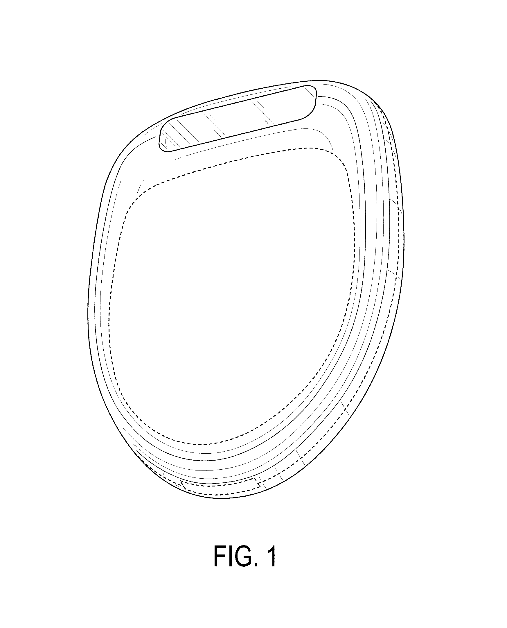
FIG. 1 is a front/right side perspective view of the wireless emitter design.
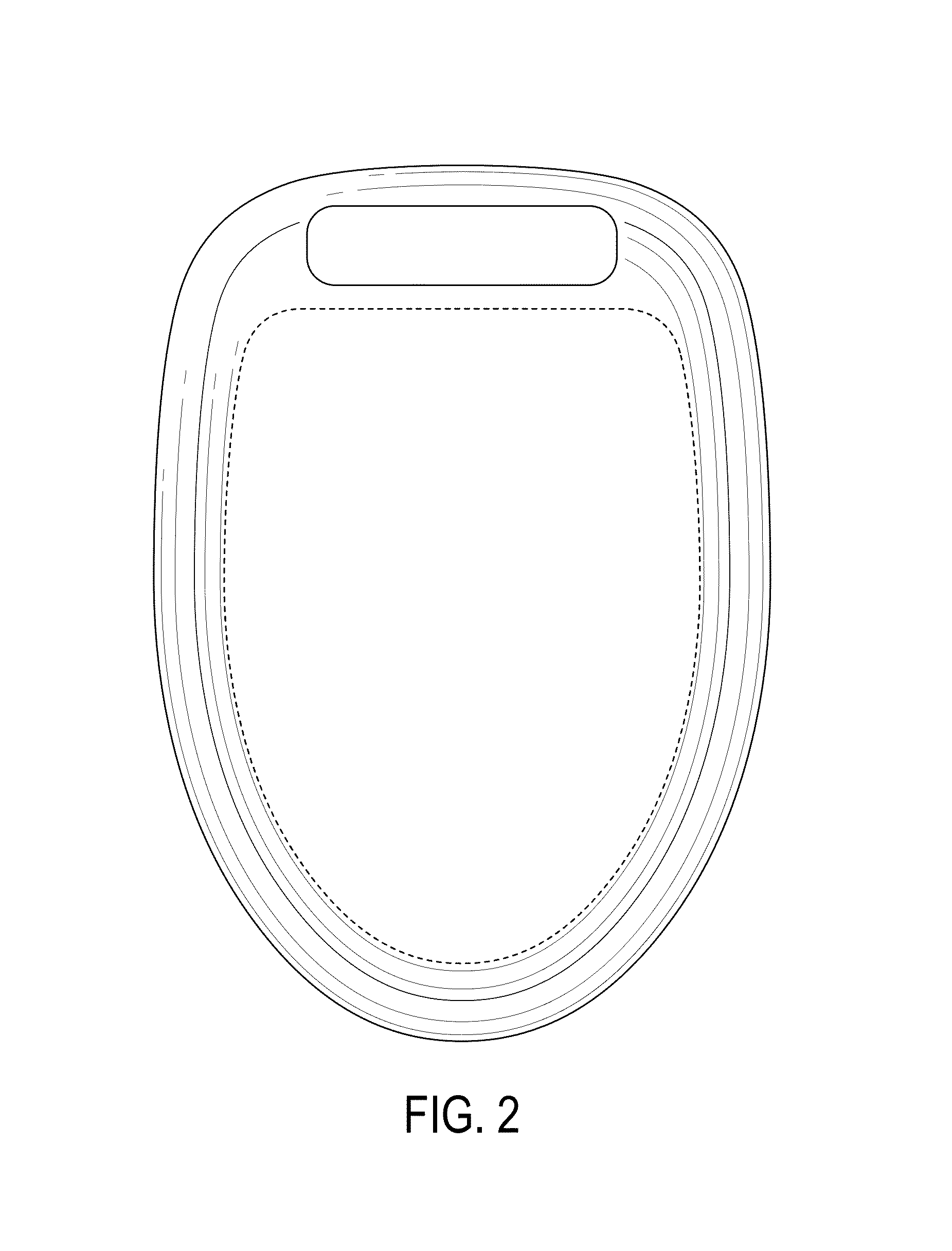
FIG. 2 is a front view of the wireless emitter design.
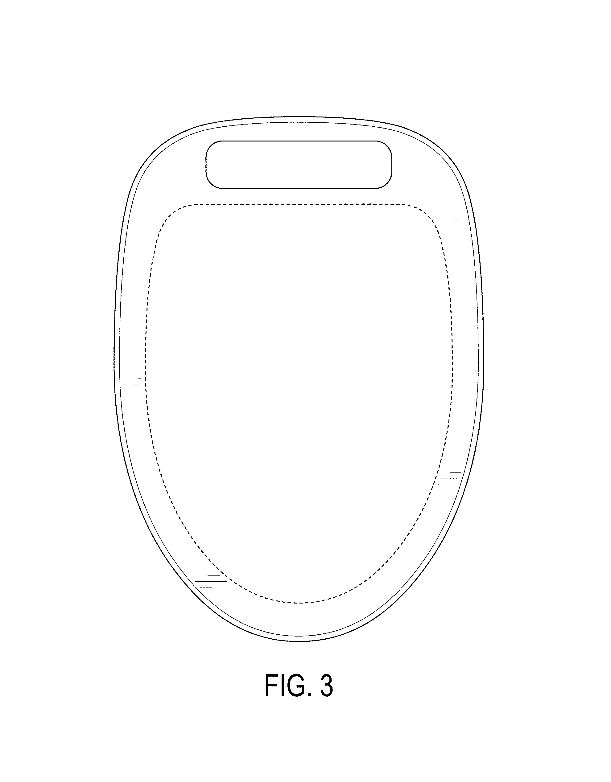
FIG. 3 is a back view of the wireless emitter design.
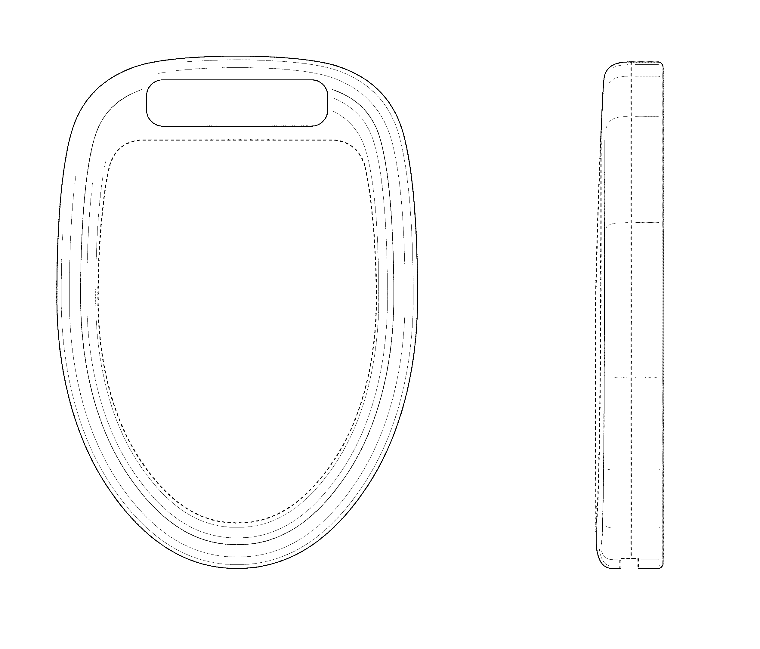
FIG. 4 is a left side view of the wireless emitter design.
FIG. 5 is a right side view of the wireless emitter design.
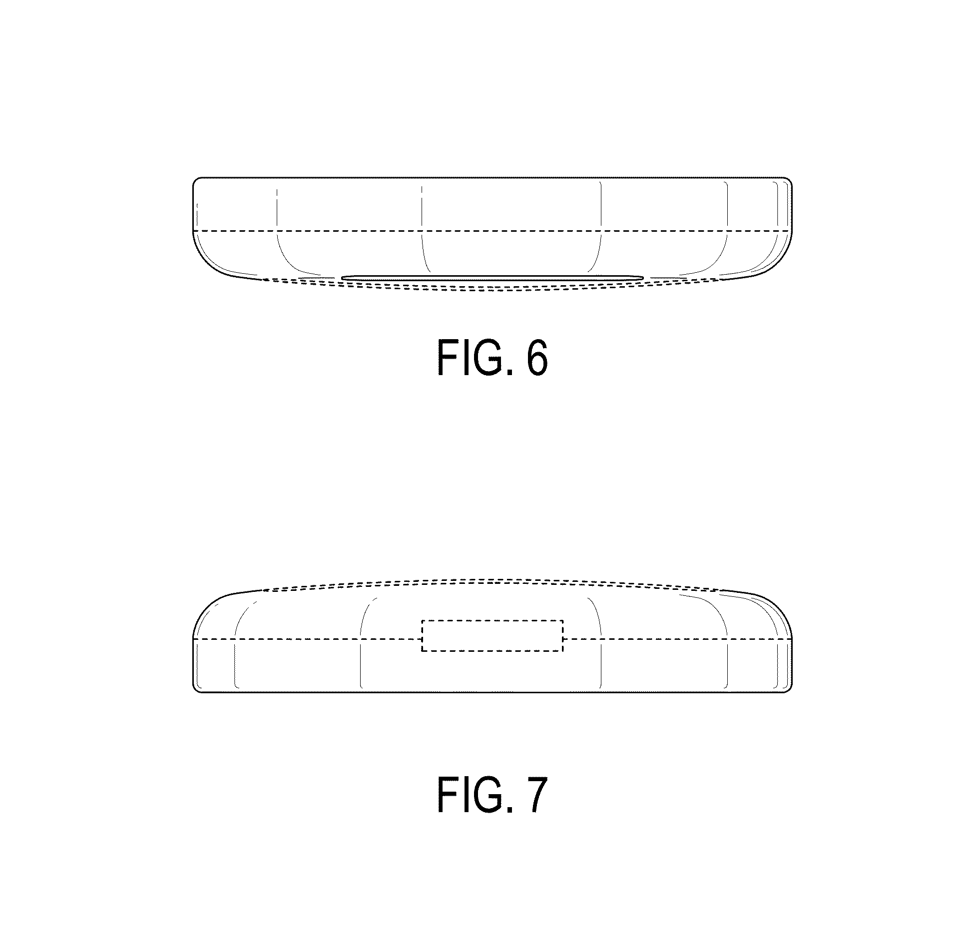
FIG. 6 is a top view of the wireless emitter design; and,
FIG. 7 is a bottom view of the wireless emitter design.
The broken lines shown in FIGS. 1-7 represent portions of the wireless emitter that form no part of the claim.
* * * * *
D00000
D00001
D00002
D00003
D00004
D00005
XML
uspto.report is an independent third-party trademark research tool that is not affiliated, endorsed, or sponsored by the United States Patent and Trademark Office (USPTO) or any other governmental organization. The information provided by uspto.report is based on publicly available data at the time of writing and is intended for informational purposes only.
While we strive to provide accurate and up-to-date information, we do not guarantee the accuracy, completeness, reliability, or suitability of the information displayed on this site. The use of this site is at your own risk. Any reliance you place on such information is therefore strictly at your own risk.
All official trademark data, including owner information, should be verified by visiting the official USPTO website at www.uspto.gov. This site is not intended to replace professional legal advice and should not be used as a substitute for consulting with a legal professional who is knowledgeable about trademark law.