Stool
Barber , et al. December 30, 2
U.S. patent number D720,143 [Application Number D/485,965] was granted by the patent office on 2014-12-30 for stool. This patent grant is currently assigned to Knoll, Inc.. The grantee listed for this patent is Knoll, Inc.. Invention is credited to Edward Barber, Jay Osgerby.

| United States Patent | D720,143 |
| Barber , et al. | December 30, 2014 |
Stool
Claims
CLAIM The ornamental design for a stool, as shown and described.
| Inventors: | Barber; Edward (London, GB), Osgerby; Jay (London, GB) | ||||||||||
|---|---|---|---|---|---|---|---|---|---|---|---|
| Applicant: |
|
||||||||||
| Assignee: | Knoll, Inc. (East Greenville,
PA) |
||||||||||
| Appl. No.: | D/485,965 | ||||||||||
| Filed: | March 25, 2014 |
| Current U.S. Class: | D6/352; D6/349 |
| Current International Class: | 0601 |
| Field of Search: | ;D6/335,340,344,347,349-355,358,360,363-373,381,685,687,688,690,691-691.6,692,692.4,694,703.15,708.21,708.22,709.22,716-716.7,717 |
References Cited [Referenced By]
U.S. Patent Documents
| 1374716 | April 1921 | Bloom et al. |
| D233108 | October 1974 | Rosen |
| D234476 | March 1975 | Rosen |
| D244107 | April 1977 | Zola |
| D285872 | September 1986 | Massonnet |
| 4998774 | March 1991 | Huff et al. |
| D399066 | October 1998 | Malatesta |
| D440415 | April 2001 | Bellini |
| D557524 | December 2007 | Simpson |
| D564244 | March 2008 | Ikaheimo |
| D579676 | November 2008 | Rheault et al. |
| D592870 | May 2009 | Olano Jauregui |
| D611737 | March 2010 | Miller et al. |
| D664779 | August 2012 | Weber et al. |
Other References
|
This is Knoll (Pt 3/4) @ Salone Milan 2013. [online] Published Apr. 10, 2013. Retrieved from URL: <http://www.dedeceblog.com/2013/04/10/knoll-celebrates-75-years-salone- -milan-2013/ 1/>. cited by examiner. |
Primary Examiner: Hattan; Susan Bennett
Assistant Examiner: Koenig; Vy
Attorney, Agent or Firm: Buchanan Ingersoll & Rooney PC
Description
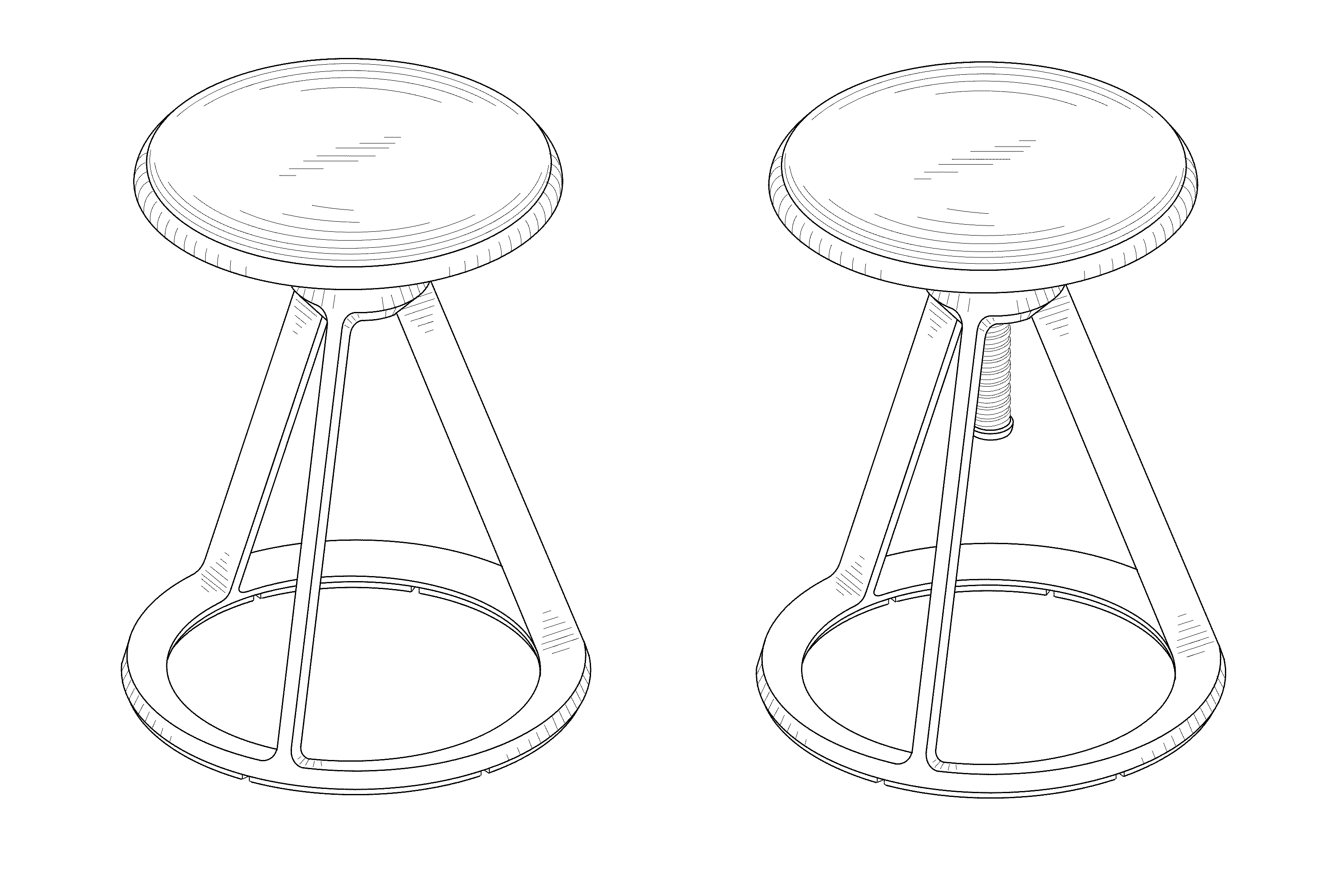
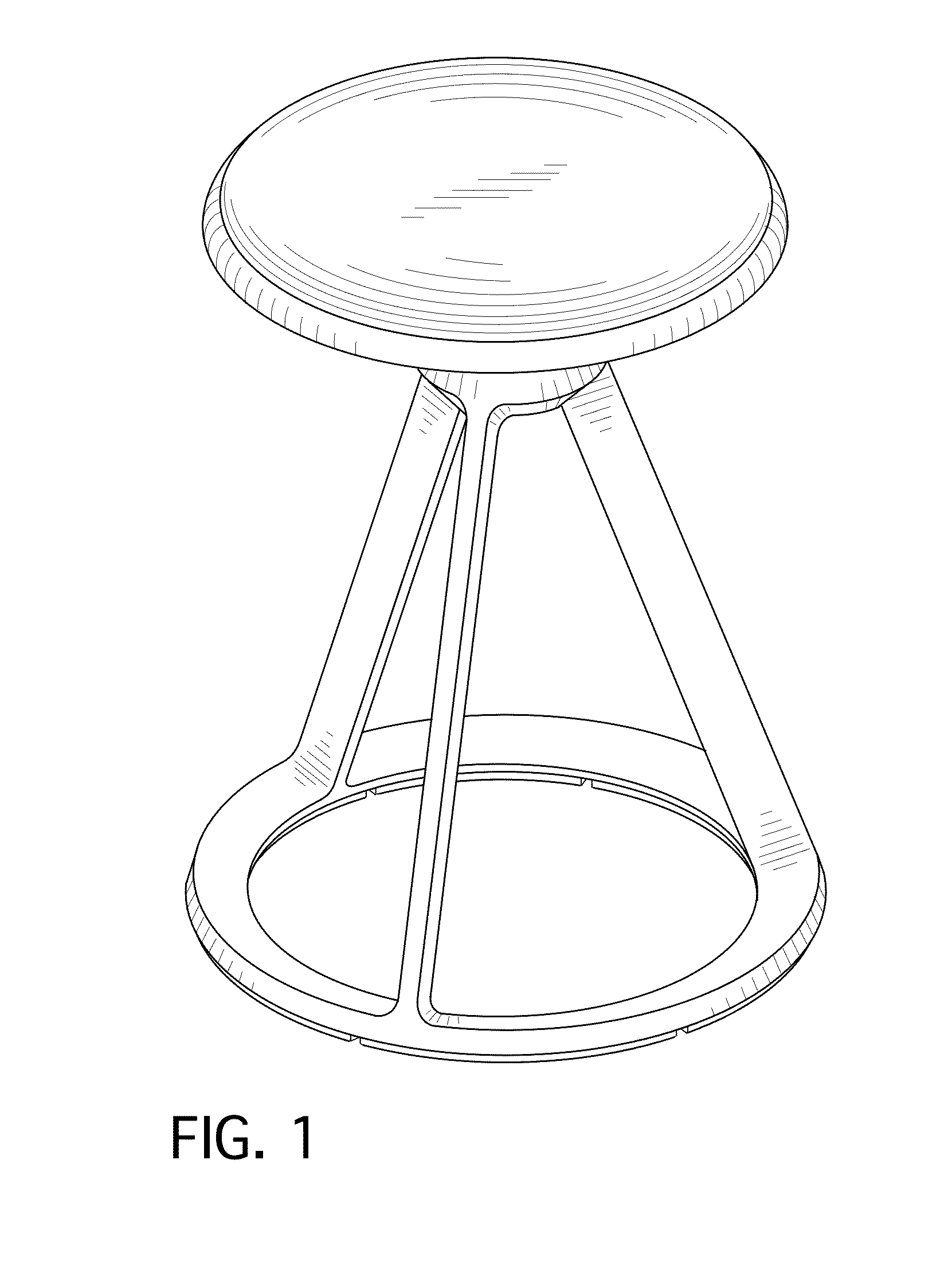
FIG. 1 is a perspective view of a stool showing our new design;
FIG. 2 is a front elevational view thereof;
FIG. 3 is a rear elevational view thereof;
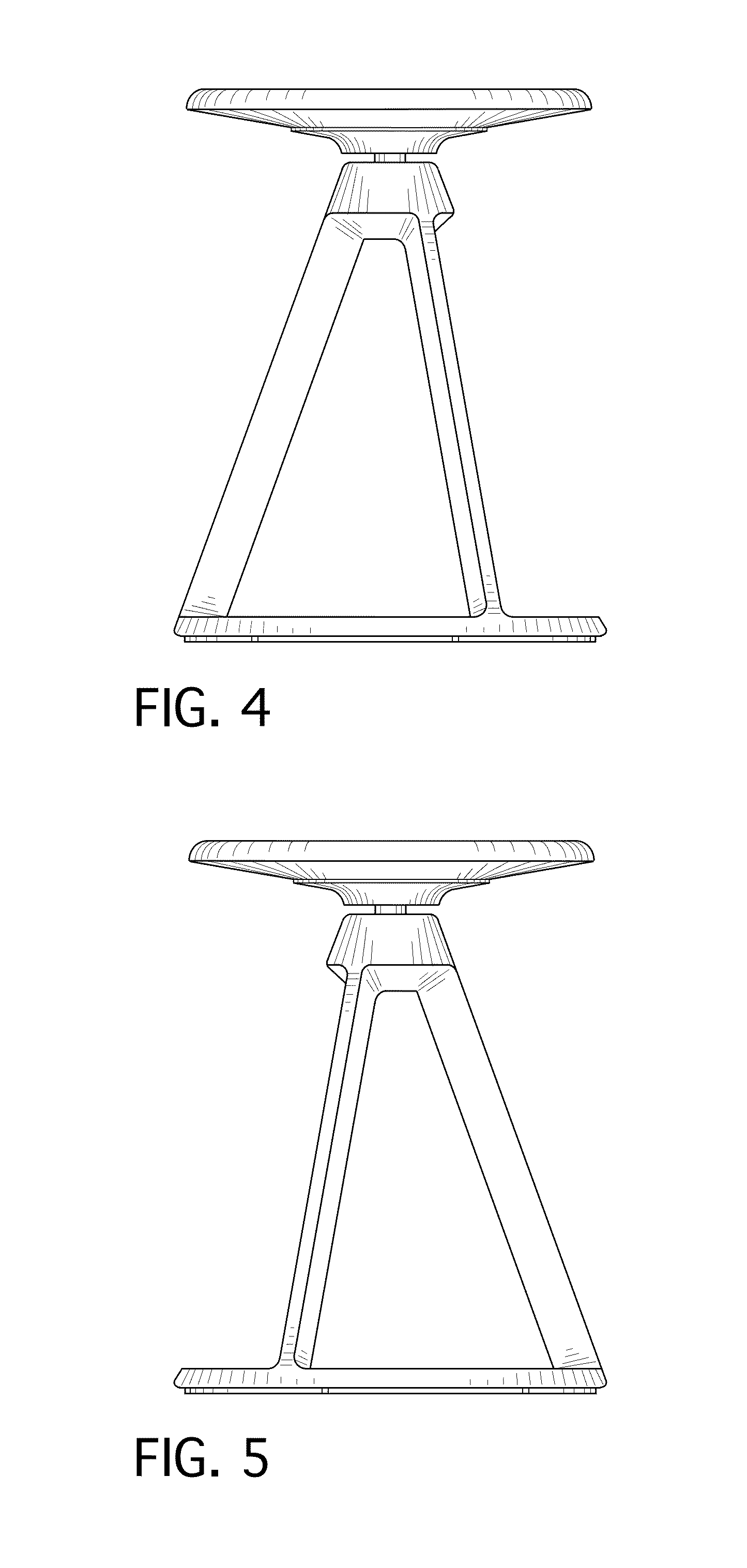
FIG. 4 is a right side elevational view thereof;
FIG. 5 is a left side elevational view thereof;
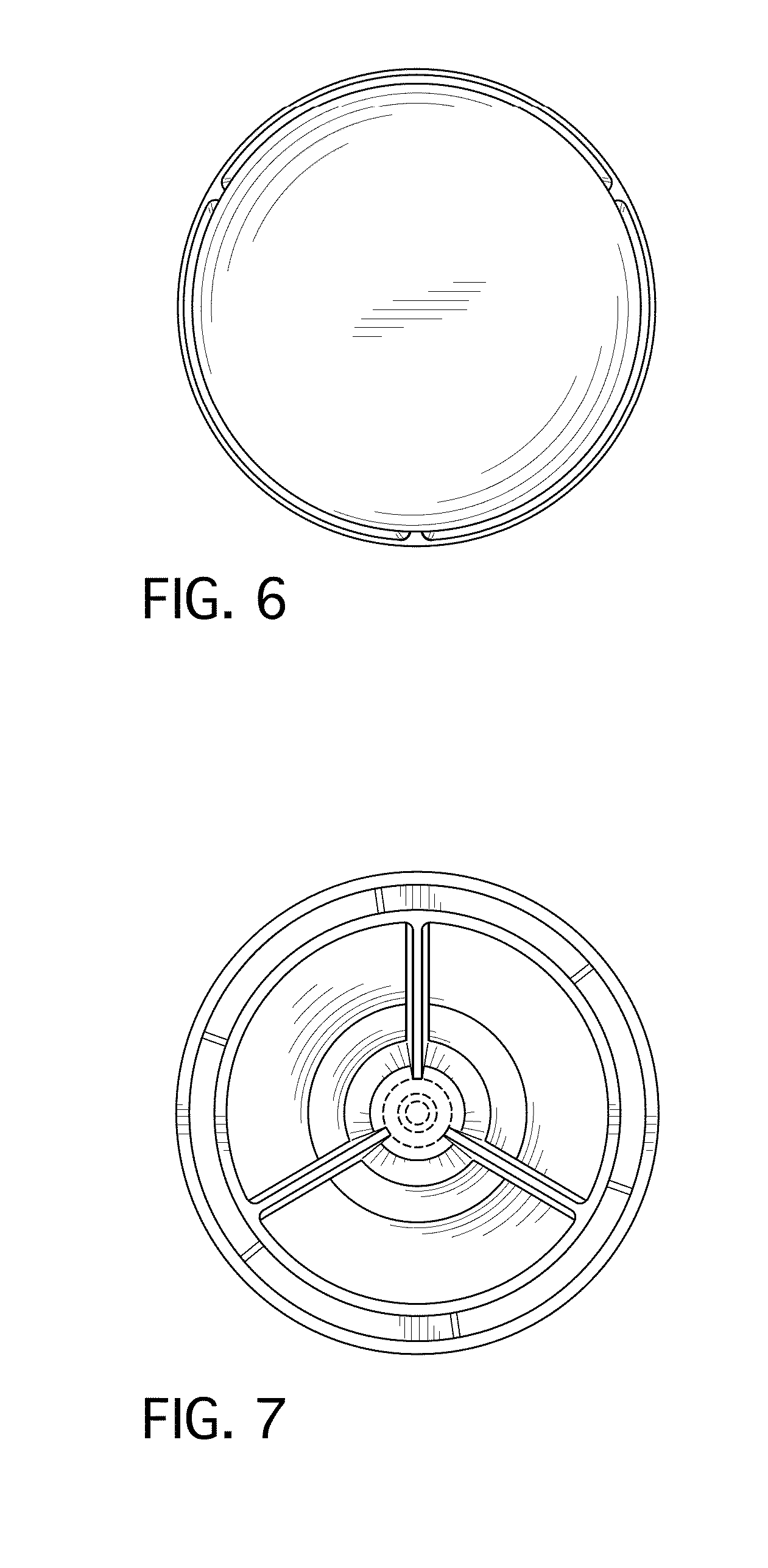
FIG. 6 is a top plan view thereof;
FIG. 7 is a bottom plan view thereof;
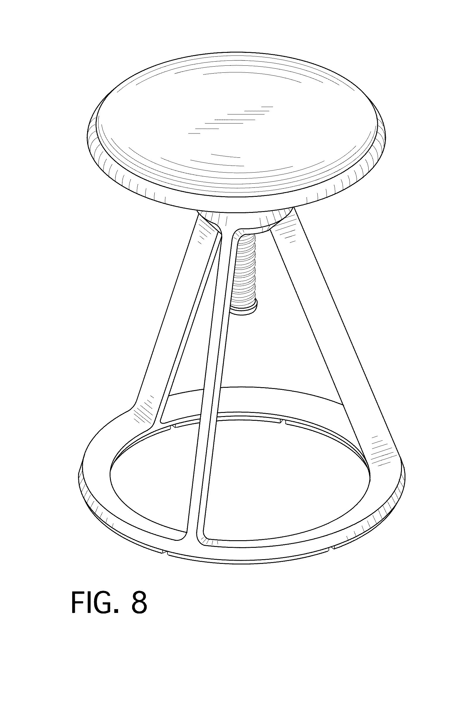
FIG. 8 is a perspective view of an alternate embodiment showing our new design;
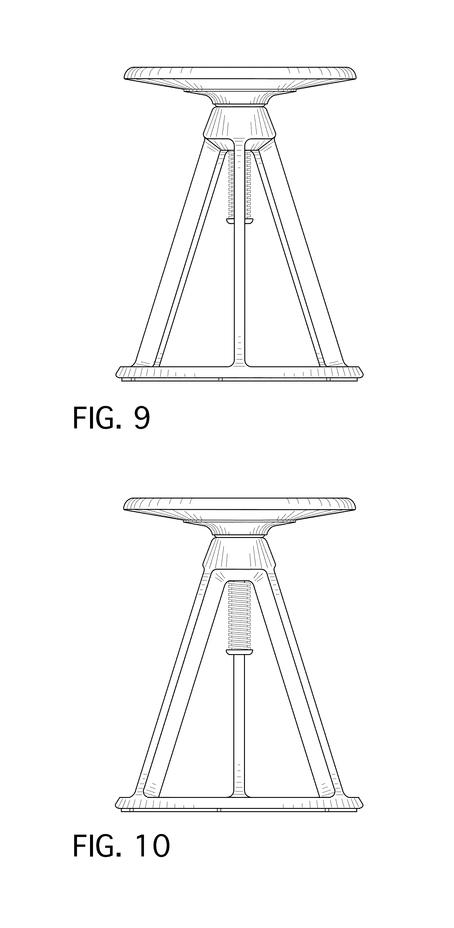
FIG. 9 is a front elevational view thereof;
FIG. 10 is a rear elevational view thereof;
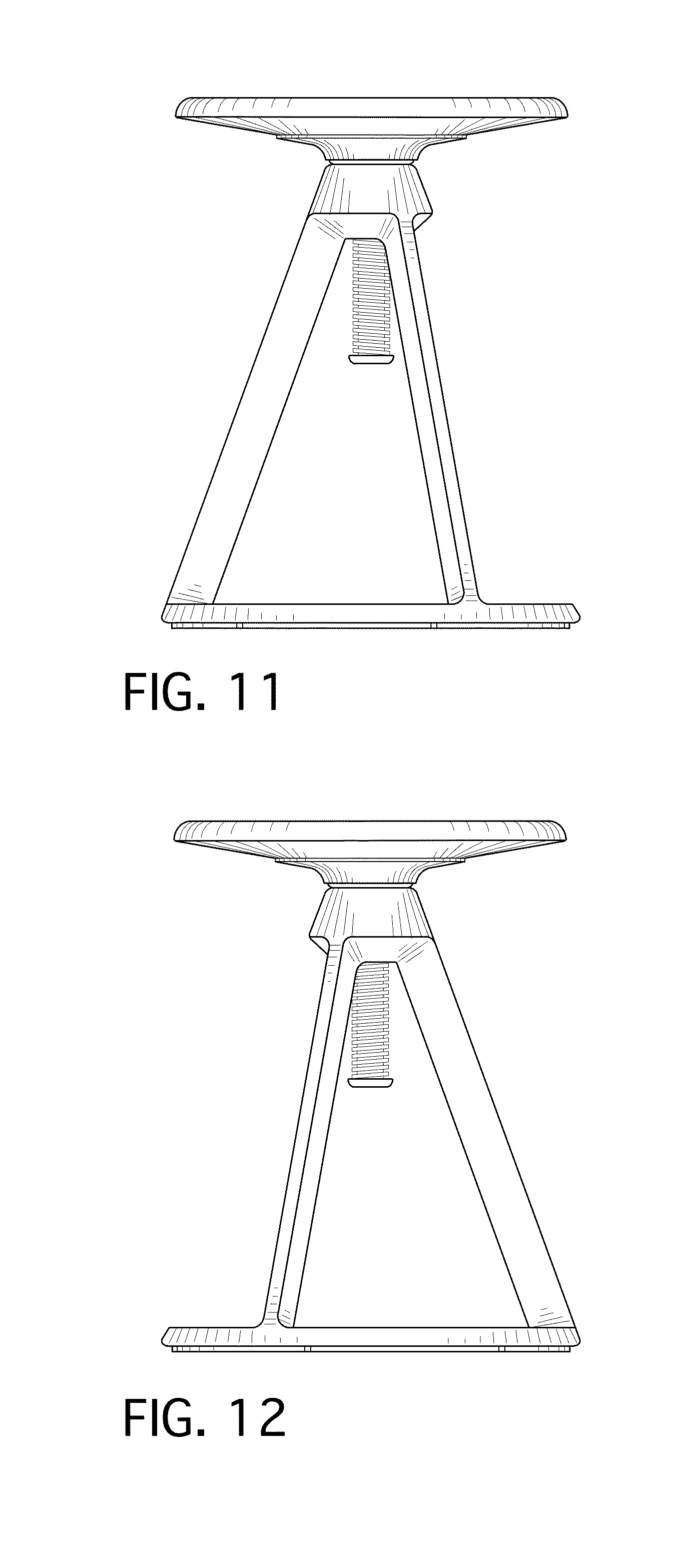
FIG. 11 is a right side elevational view thereof;
FIG. 12 is a left side elevational view thereof;
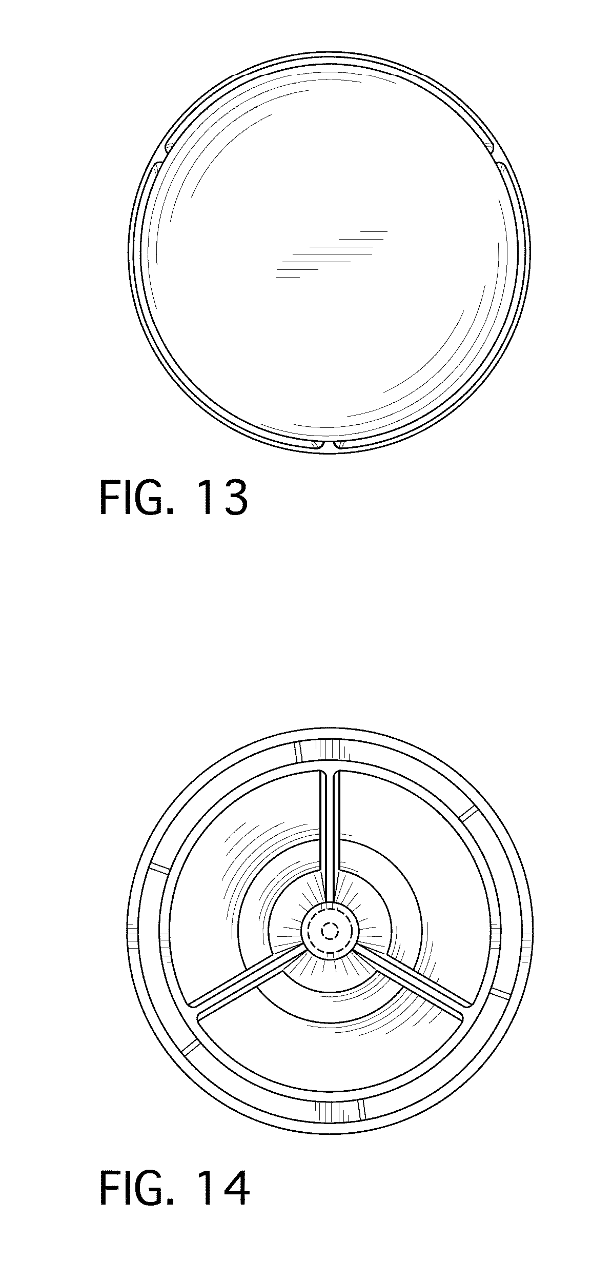
FIG. 13 is a top plan view thereof; and,
FIG. 14 is a bottom plan view thereof.
The broken lines shown represent environmental subject matter and form no part of the claimed design.
* * * * *
References
D00000
D00001
D00002
D00003
D00004
D00005
D00006
D00007
D00008
XML
uspto.report is an independent third-party trademark research tool that is not affiliated, endorsed, or sponsored by the United States Patent and Trademark Office (USPTO) or any other governmental organization. The information provided by uspto.report is based on publicly available data at the time of writing and is intended for informational purposes only.
While we strive to provide accurate and up-to-date information, we do not guarantee the accuracy, completeness, reliability, or suitability of the information displayed on this site. The use of this site is at your own risk. Any reliance you place on such information is therefore strictly at your own risk.
All official trademark data, including owner information, should be verified by visiting the official USPTO website at www.uspto.gov. This site is not intended to replace professional legal advice and should not be used as a substitute for consulting with a legal professional who is knowledgeable about trademark law.