Calibrator case
Elrod December 30, 2
U.S. patent number D720,243 [Application Number D/449,322] was granted by the patent office on 2014-12-30 for calibrator case. This patent grant is currently assigned to Fluke Corporation. The grantee listed for this patent is Fluke Corporation. Invention is credited to Jeffrey Elrod.
View All Diagrams
| United States Patent | D720,243 |
| Elrod | December 30, 2014 |
Calibrator case
Claims
CLAIM The ornamental design for a calibrator case, as shown and described.
| Inventors: | Elrod; Jeffrey (Seattle, WA) | ||||||||||
|---|---|---|---|---|---|---|---|---|---|---|---|
| Applicant: |
|
||||||||||
| Assignee: | Fluke Corporation (Everett,
WA) |
||||||||||
| Appl. No.: | D/449,322 | ||||||||||
| Filed: | March 14, 2013 |
| Current U.S. Class: | D10/52; D10/57 |
| Current International Class: | 1004 |
| Field of Search: | ;D10/78,52,53,57 ;374/1-3,158,129,209,163,172,E15.001,E7.042 ;600/184,474,549 ;702/99 |
References Cited [Referenced By]
U.S. Patent Documents
| 4428685 | January 1984 | Lemelson et al. |
| 4479596 | October 1984 | Swanson |
| 4601589 | July 1986 | Meisner |
| 5025966 | June 1991 | Potter |
| 5535928 | July 1996 | Herring |
| 5655305 | August 1997 | Fletcher |
| D410204 | May 1999 | Hendriks |
| 6076789 | June 2000 | Jackson |
| 6209769 | April 2001 | Seals et al. |
| D446135 | August 2001 | Chen |
| D448314 | September 2001 | Chen |
| 6318687 | November 2001 | Trana |
| D460923 | July 2002 | Chen |
| 6412674 | July 2002 | Lipke |
| D481321 | October 2003 | Knieriem et al. |
| D504335 | April 2005 | Stevenson et al. |
| 6880737 | April 2005 | Bauer |
| D535202 | January 2007 | Sisk et al. |
| 7192186 | March 2007 | Blakeley, III |
| 7255475 | August 2007 | Quinn et al. |
| 7640632 | January 2010 | Lazarus |
| 7722747 | May 2010 | Keigler et al. |
| 8123401 | February 2012 | Price |
| 8449476 | May 2013 | Waldhoff et al. |
| D689381 | September 2013 | Branck et al. |
| 8727608 | May 2014 | Blakeley, III |
| 2006/0196069 | September 2006 | Groepper |
| 2013/0170823 | July 2013 | McDonald |
| 2014/0042294 | February 2014 | Marzynski et al. |
| 00/02362 | Jan 2000 | WO | |||
Other References
|
European Search Report dated Nov. 19, 2013, in European Application No. 13152473.8, filed Jan. 24, 2013, 8 pages. cited by applicant. |
Primary Examiner: Davis; Antoine D
Attorney, Agent or Firm: Christensen O'Connor Johnson Kindness PLLC
Description
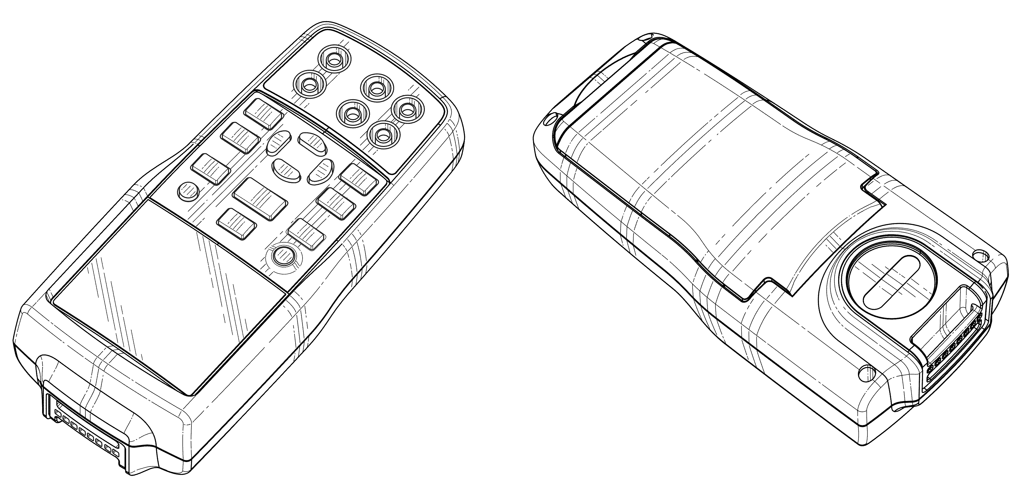
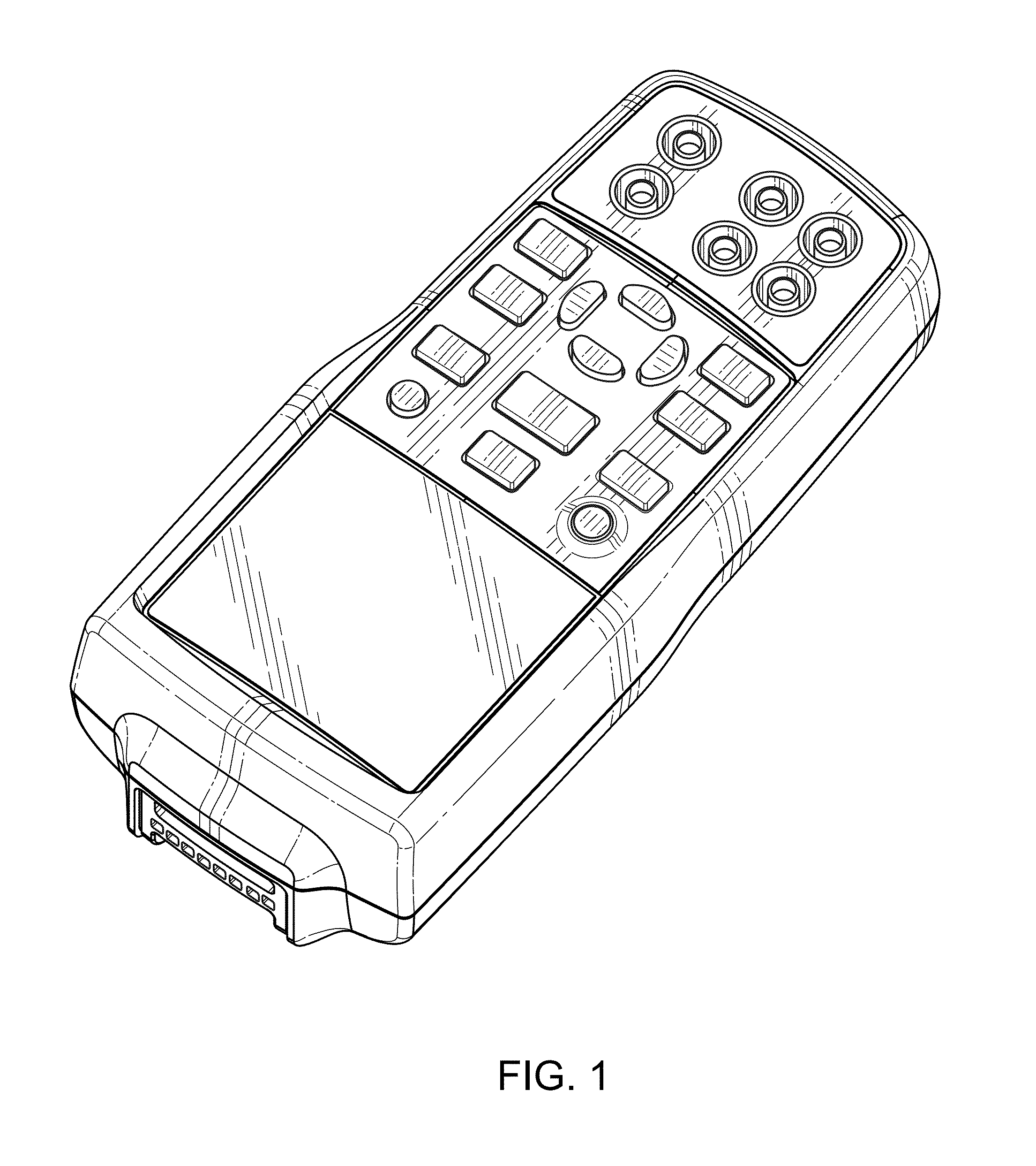
FIG. 1 is a front perspective view of a calibrator case.
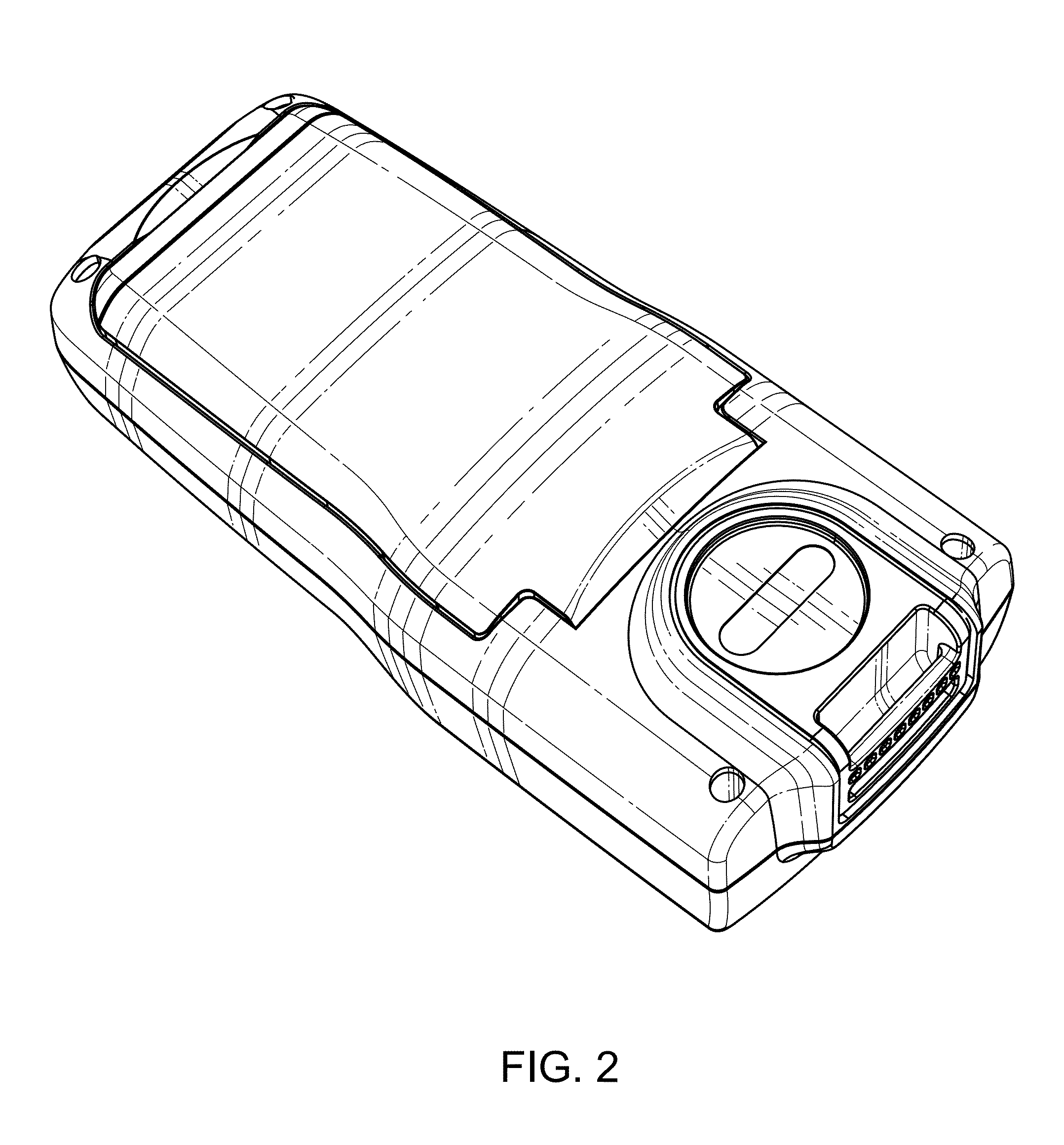
FIG. 2 is a back perspective view thereof.
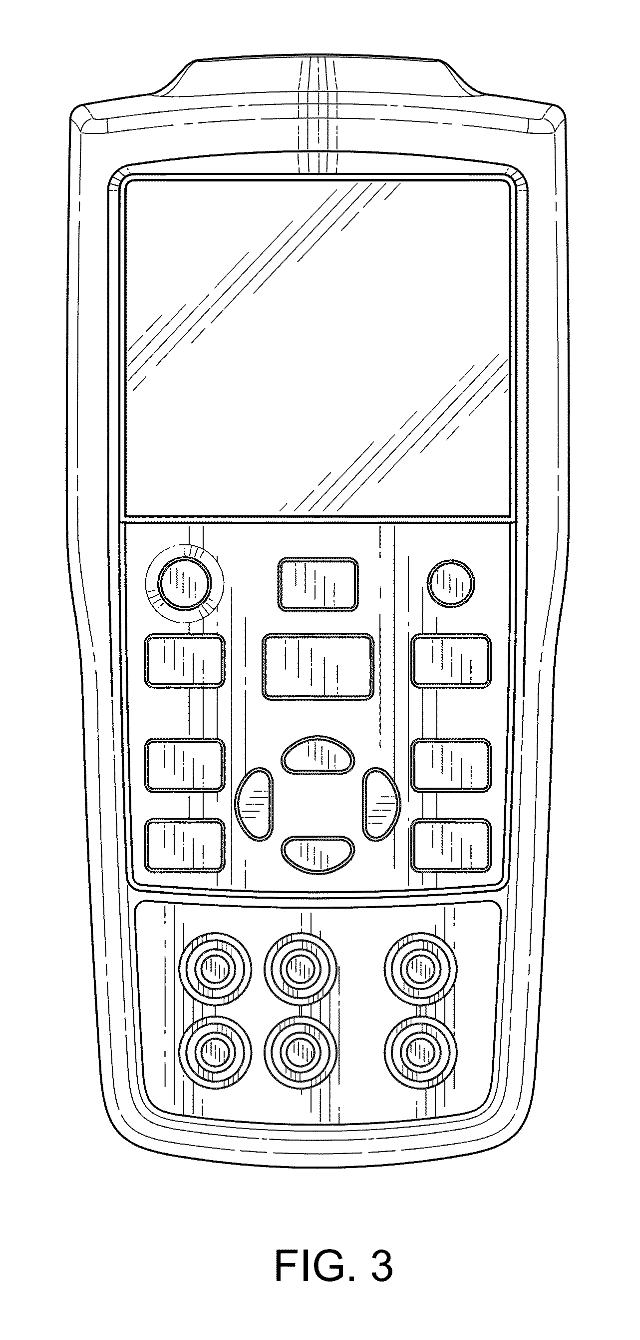
FIG. 3 is a front plan view thereof.
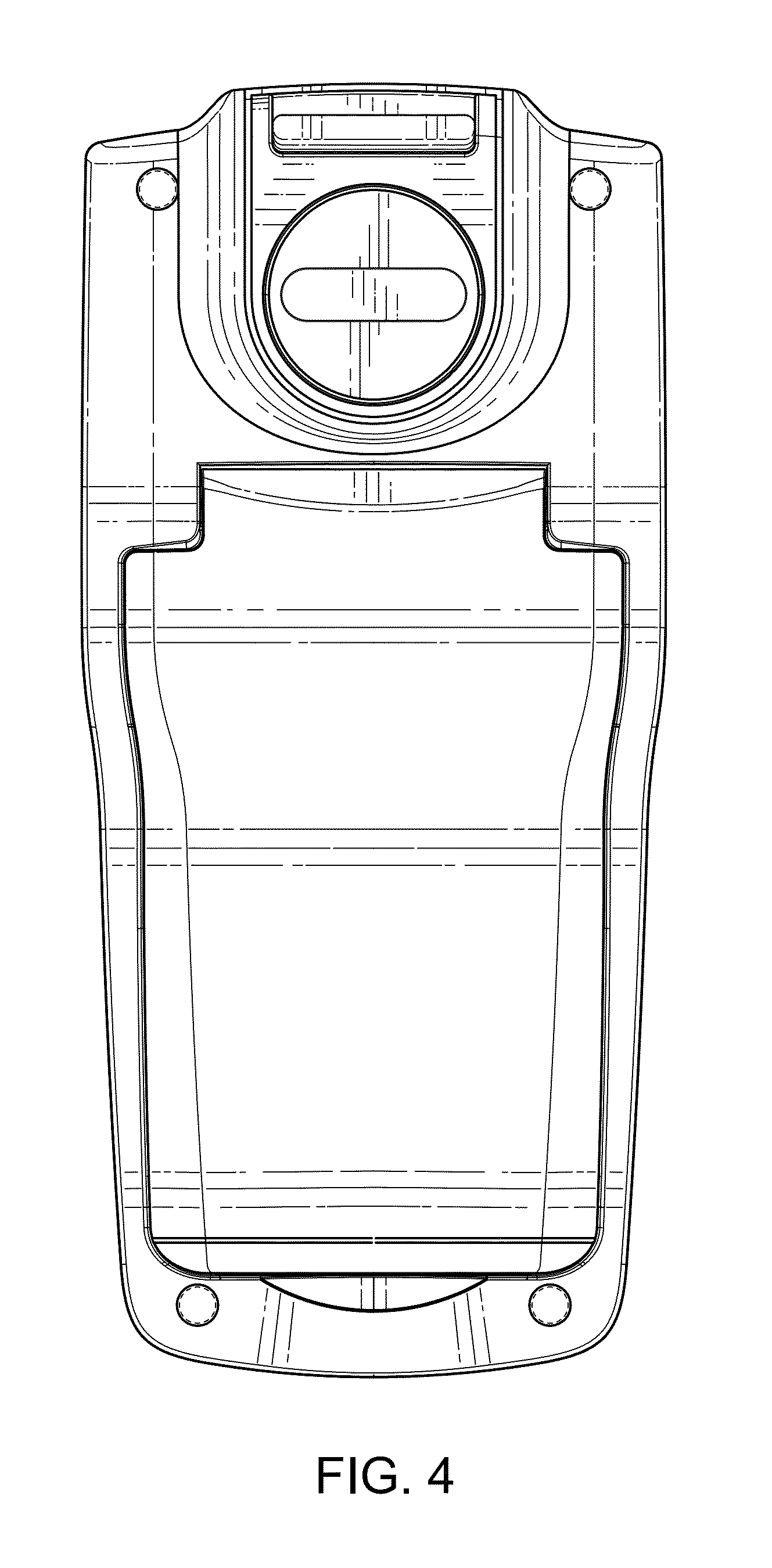
FIG. 4 is a back plan view thereof.
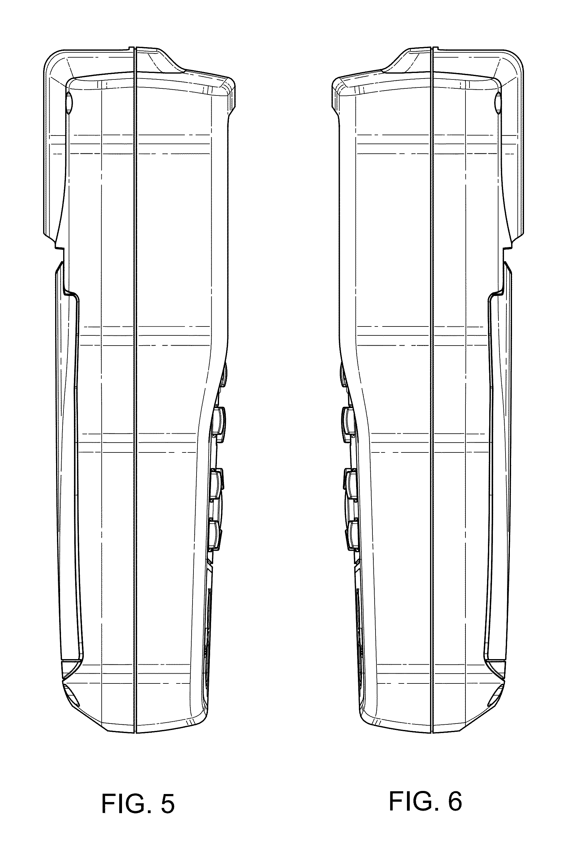
FIG. 5 is a left view thereof.
FIG. 6 is a right view thereof.
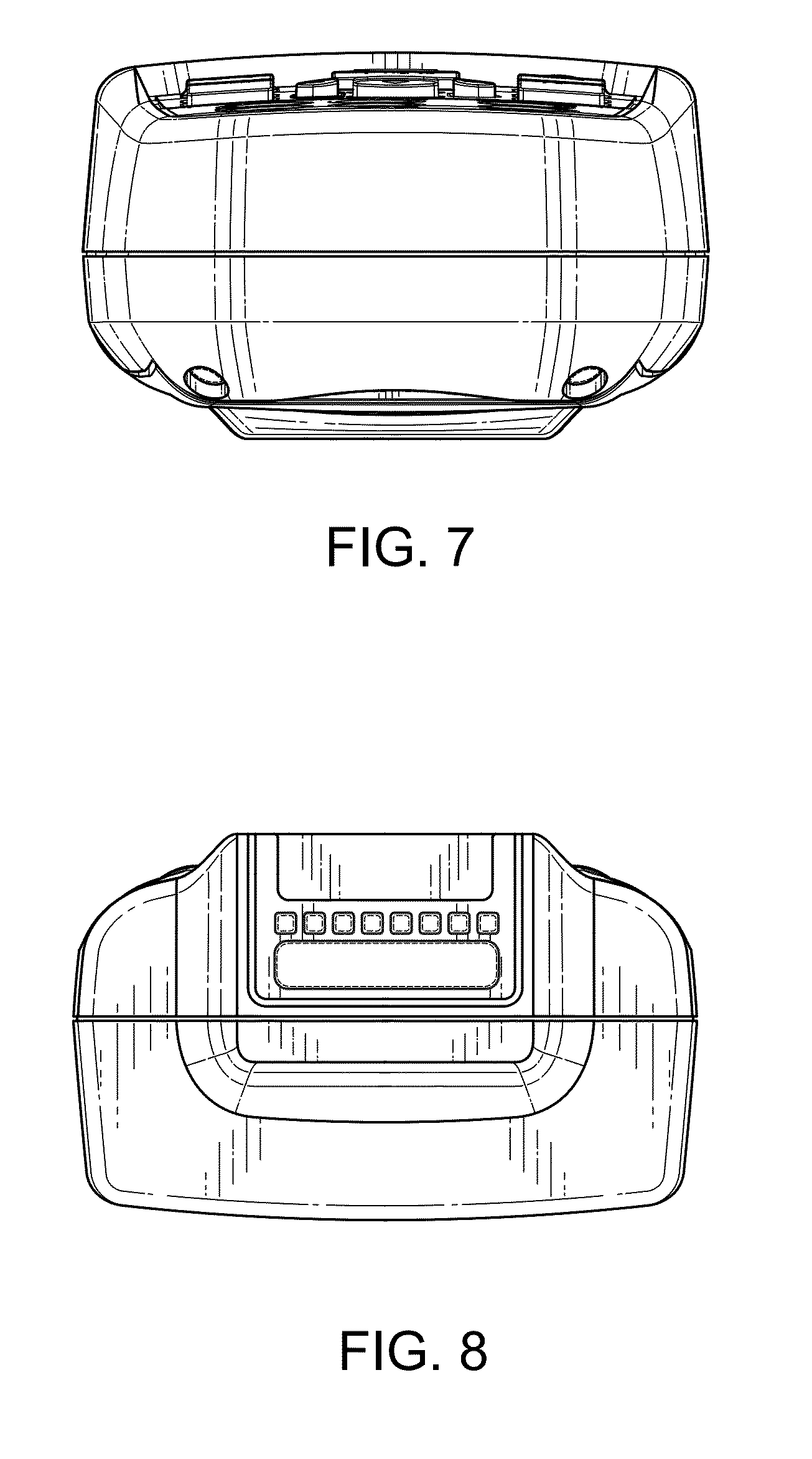
FIG. 7 is a bottom view thereof.
FIG. 8 is a top view thereof.
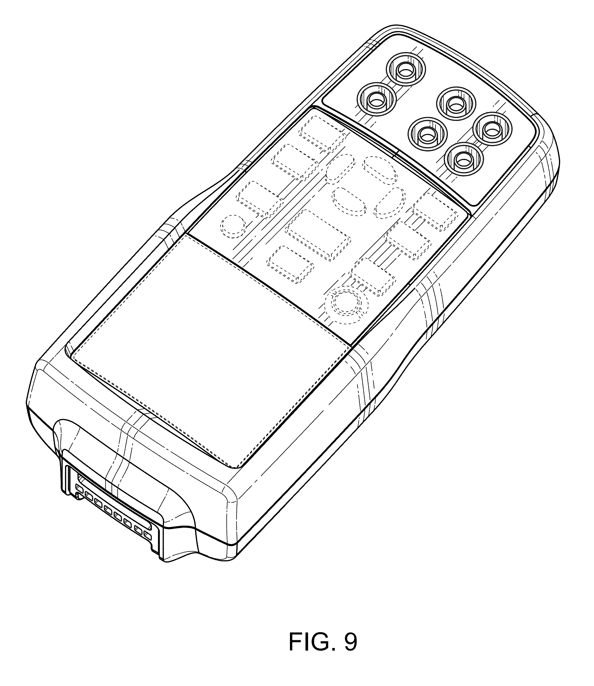
FIG. 9 is a front perspective view of a second embodiment of a calibrator case.
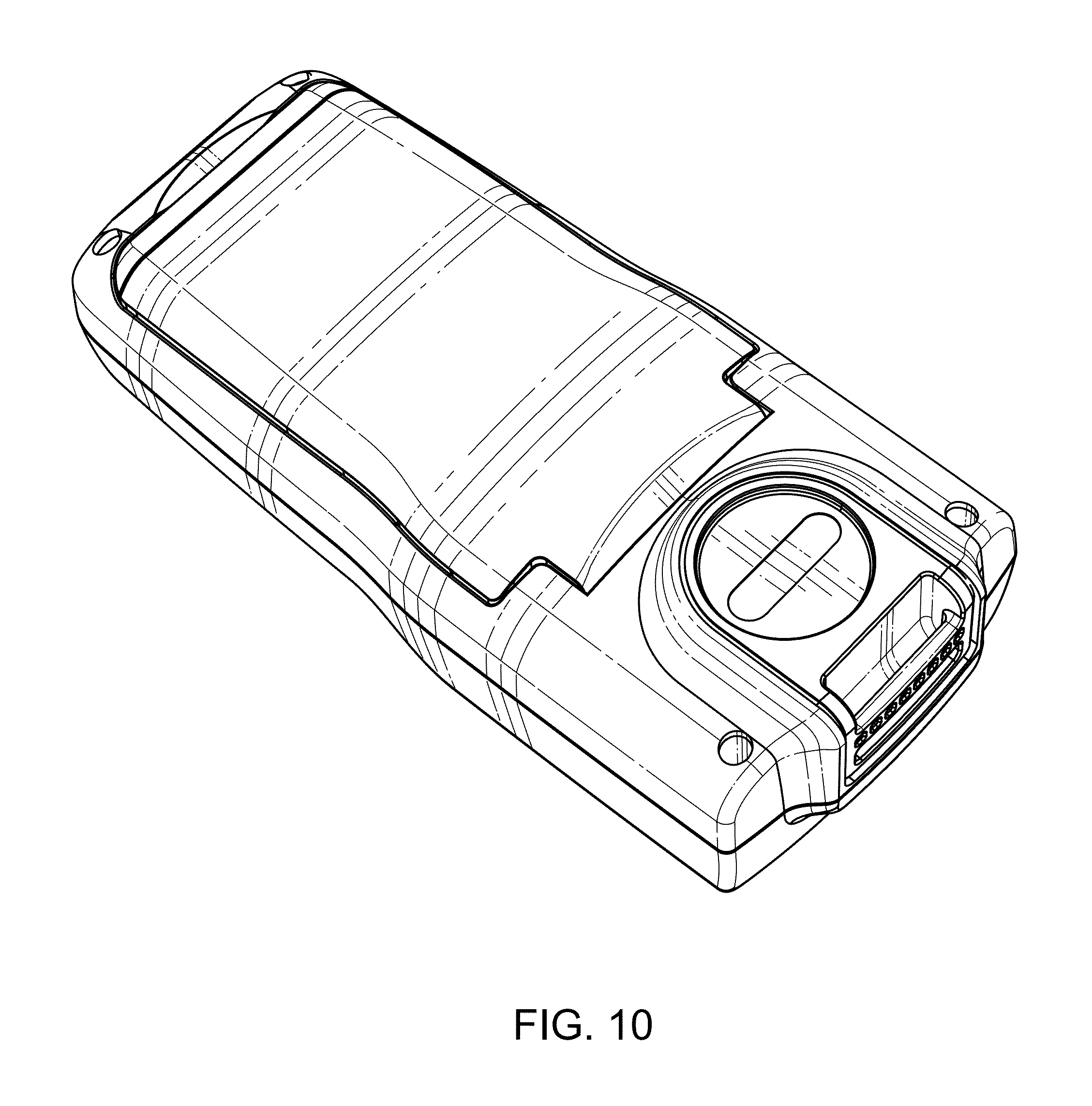
FIG. 10 is a back perspective view thereof.
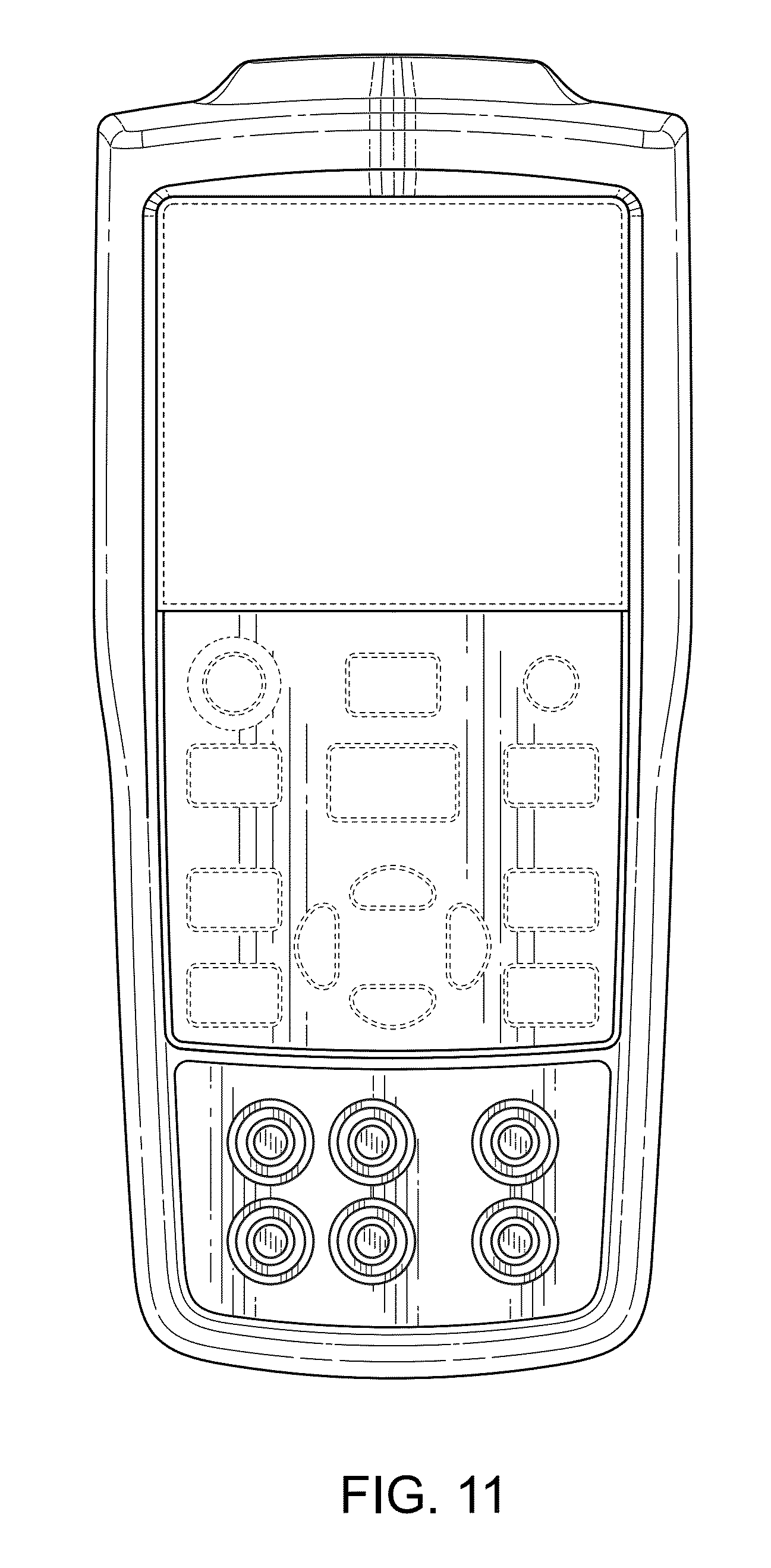
FIG. 11 is a front plan view thereof.
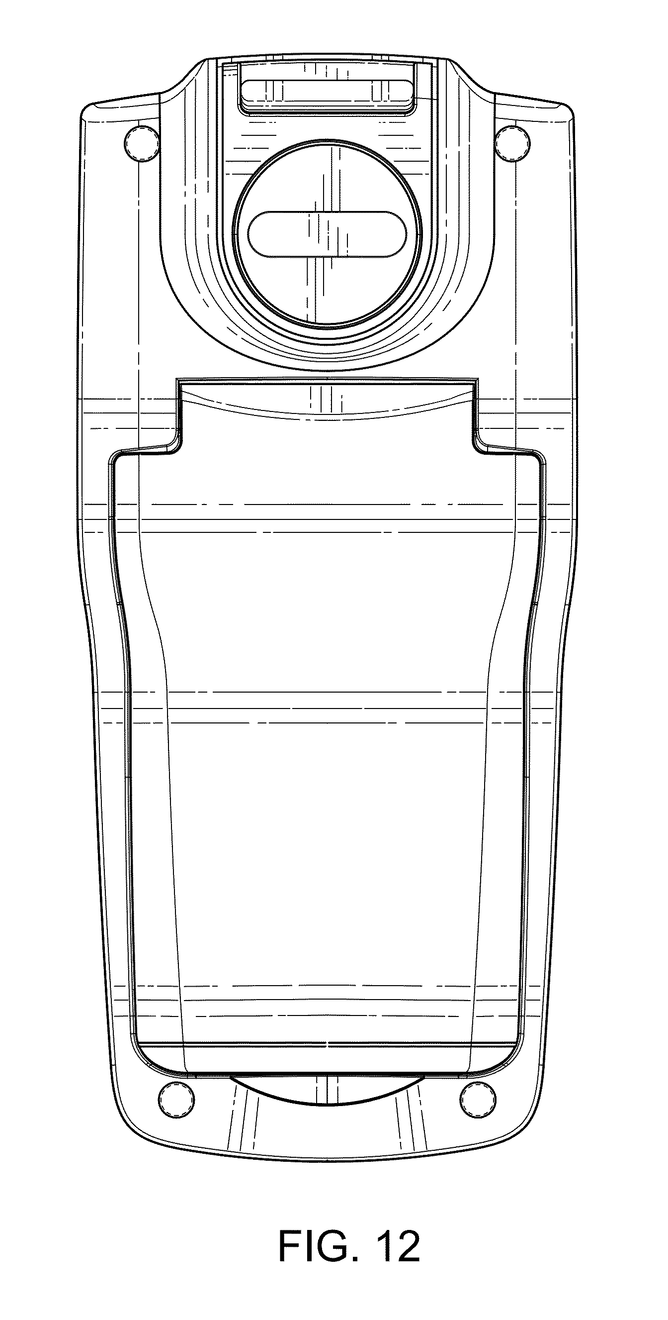
FIG. 12 is a back plan view thereof.
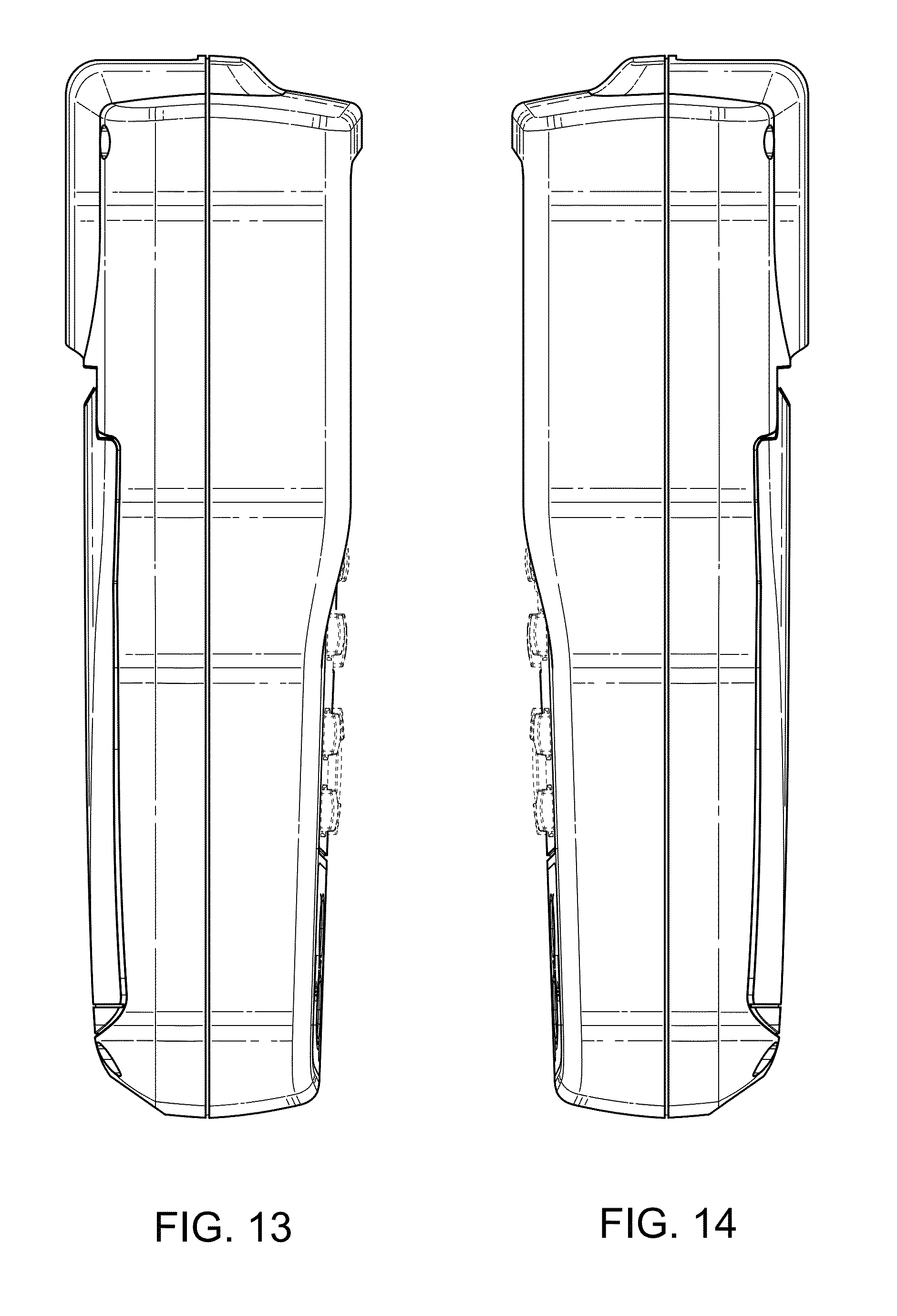
FIG. 13 is a left view thereof.
FIG. 14 is a right view thereof.
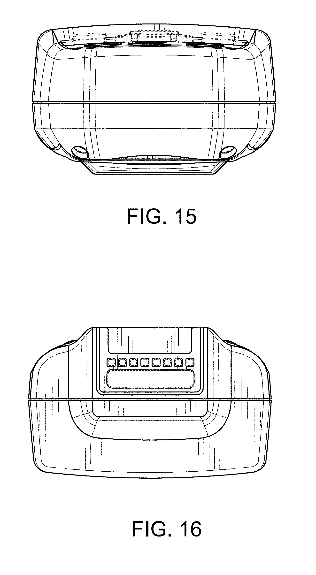
FIG. 15 is a bottom view thereof.
FIG. 16 is a top view thereof.
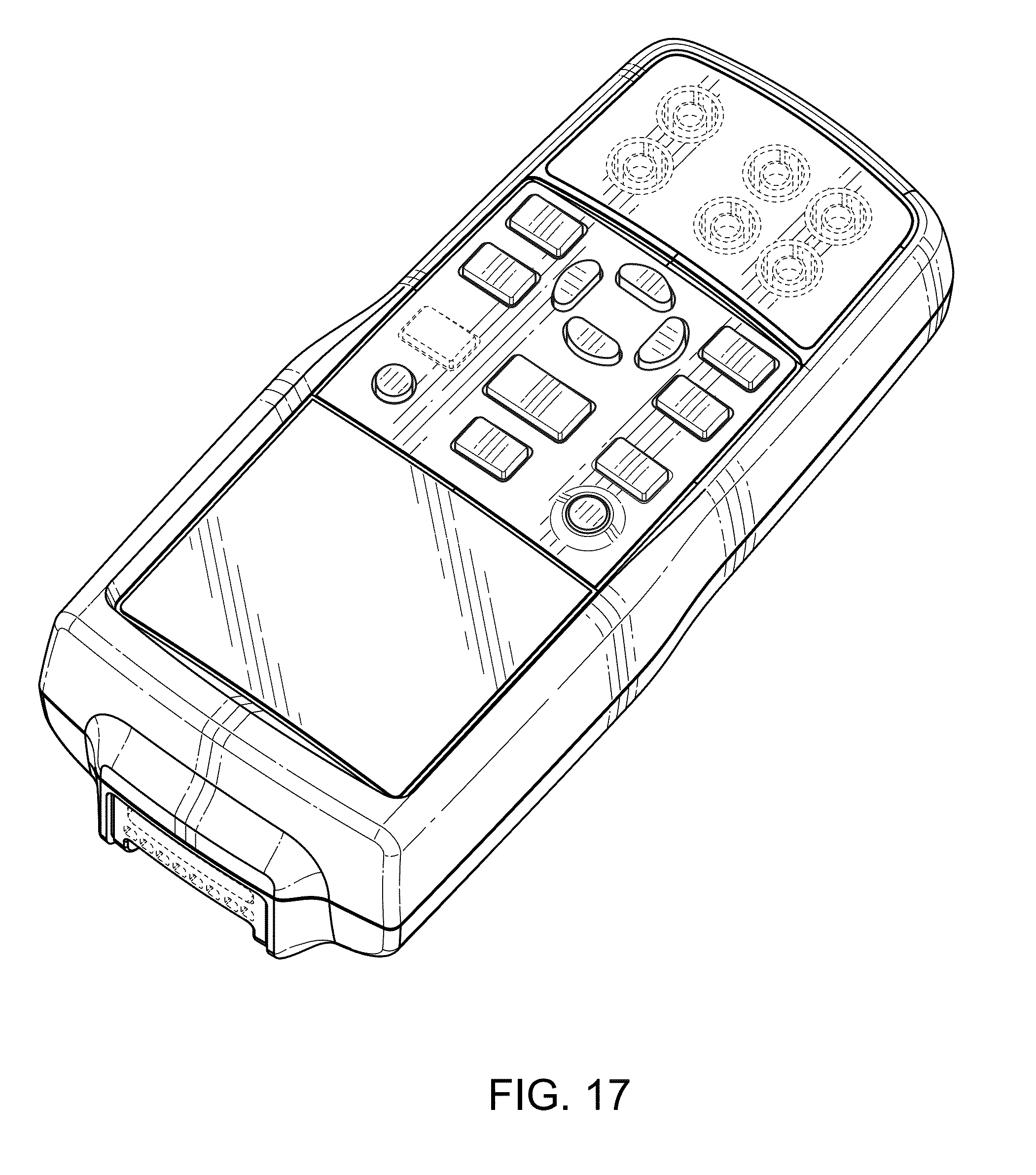
FIG. 17 is a front perspective view of a third embodiment of a calibrator case.
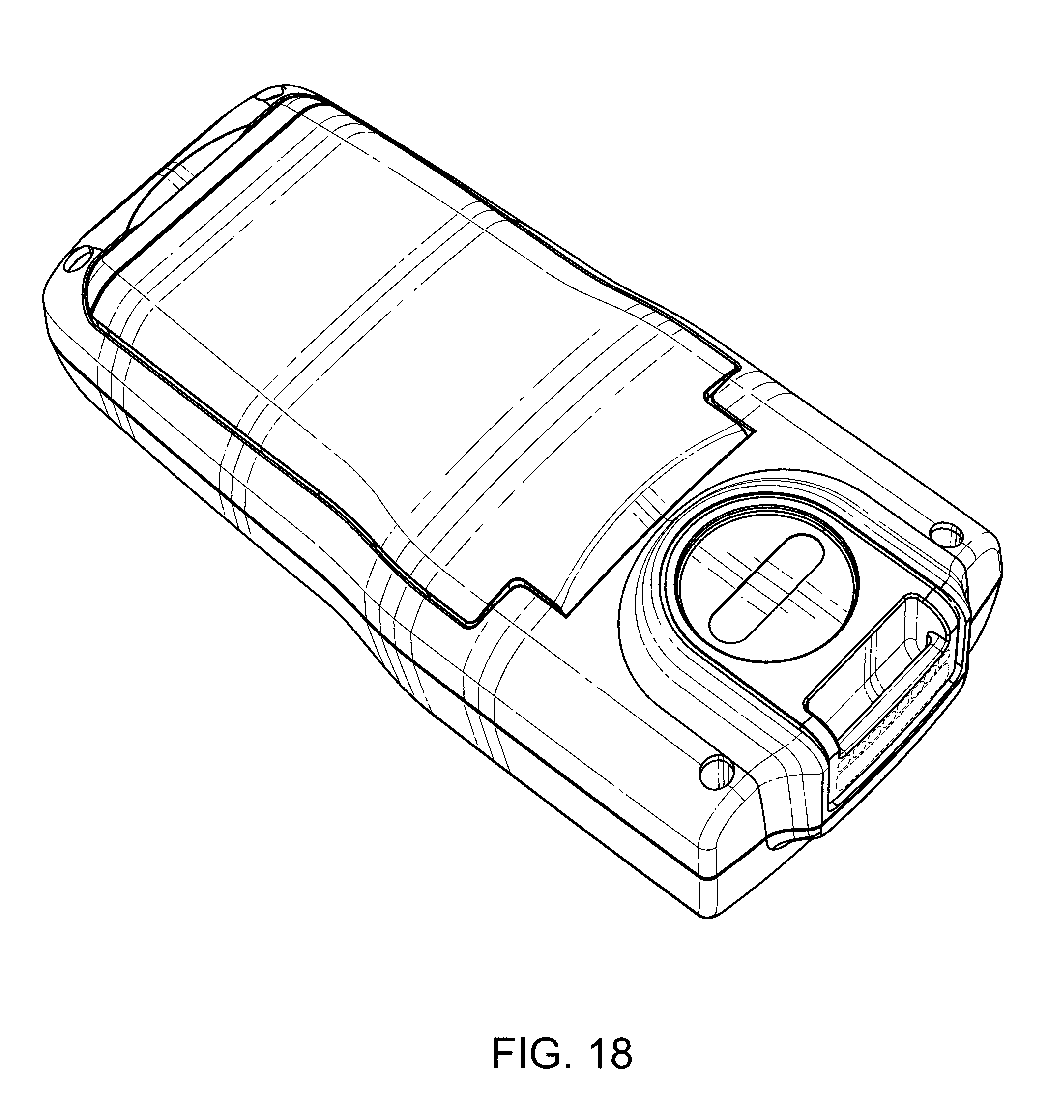
FIG. 18 is a back perspective view thereof.
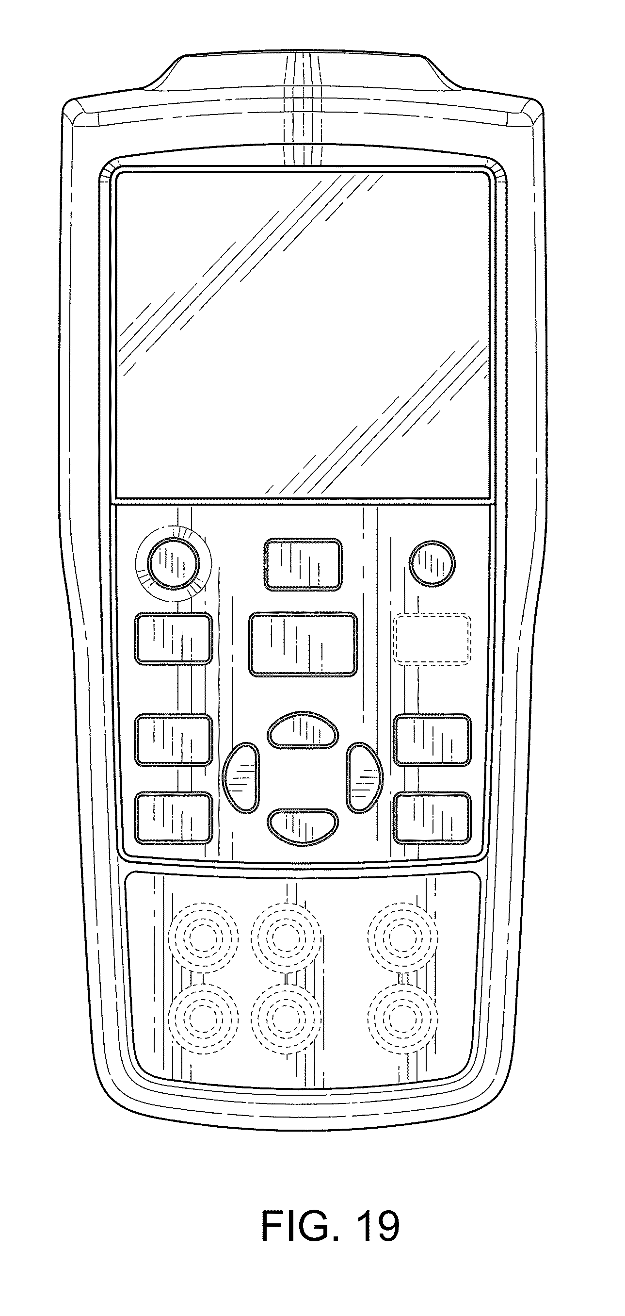
FIG. 19 is a front plan view thereof.
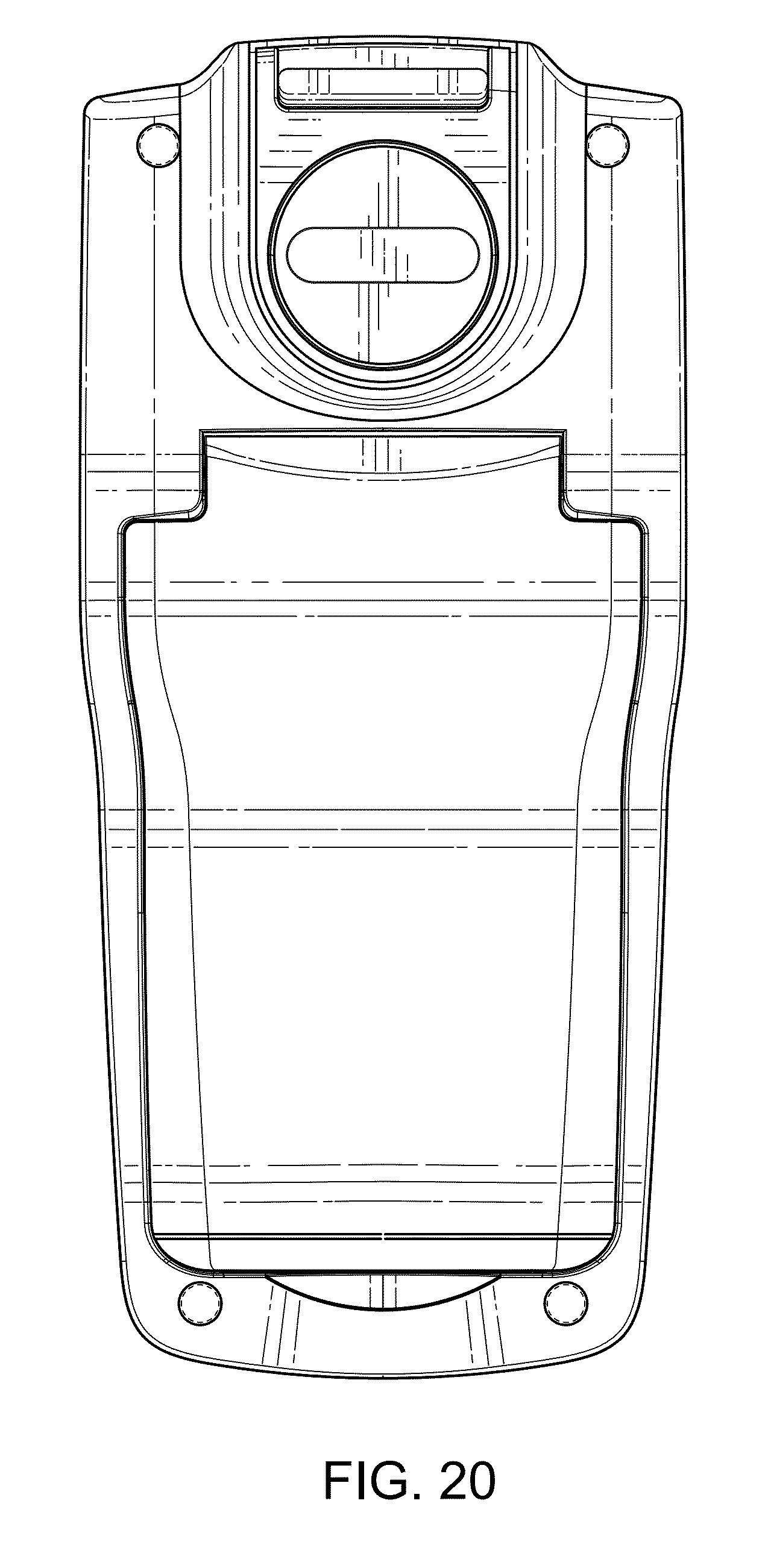
FIG. 20 is a back plan view thereof.
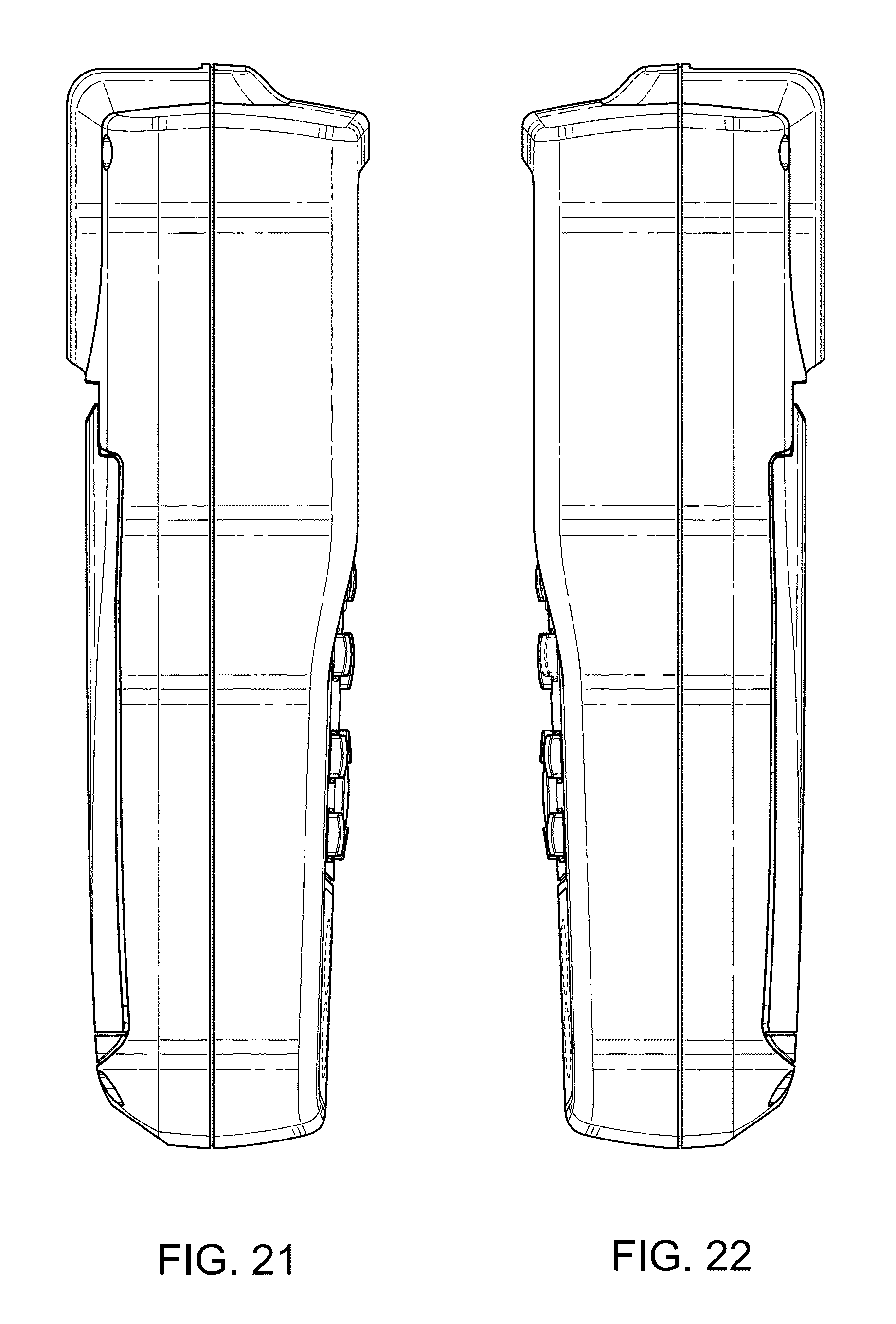
FIG. 21 is a left view thereof.
FIG. 22 is a right view thereof.
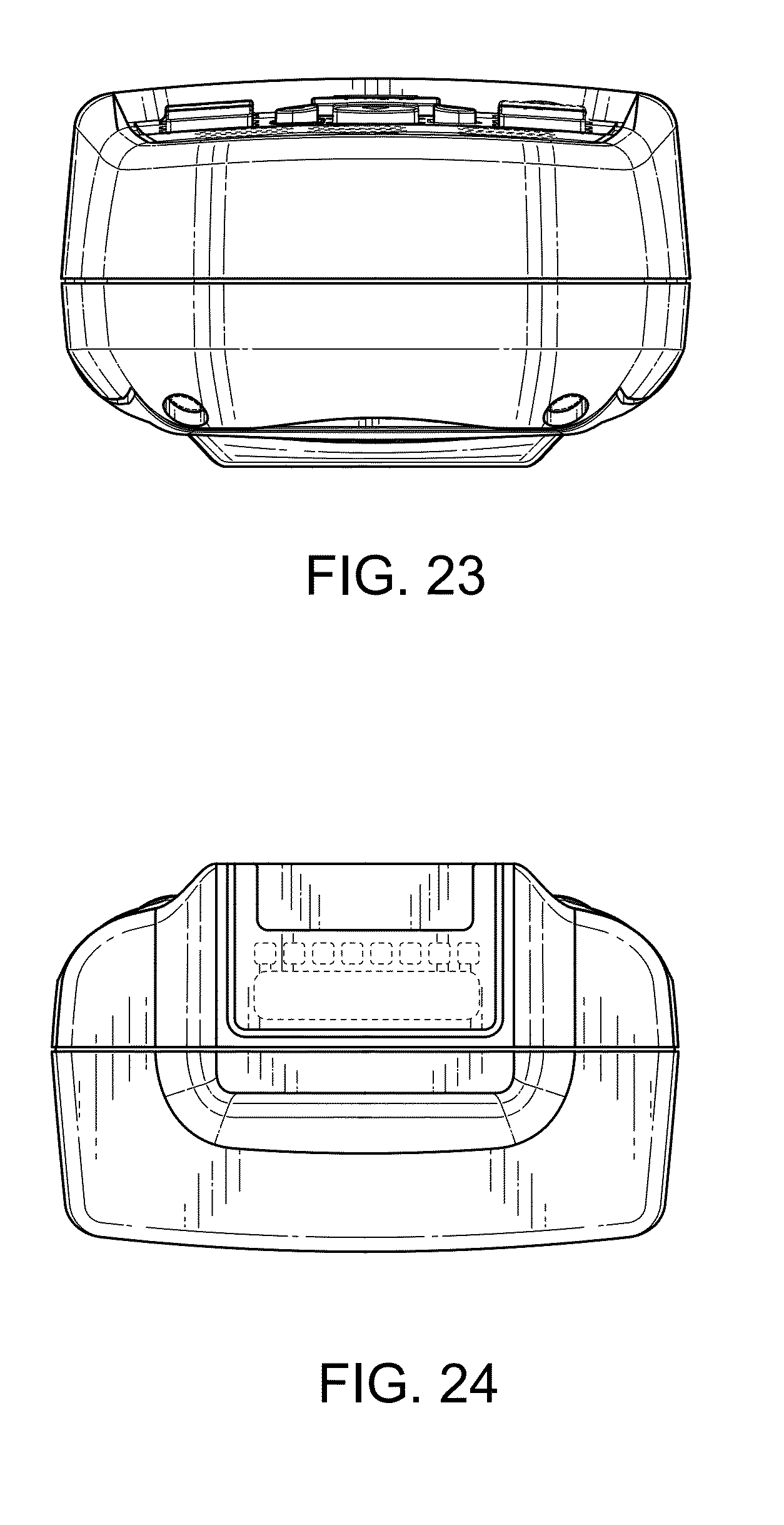
FIG. 23 is a bottom view thereof.
FIG. 24 is a top view thereof.
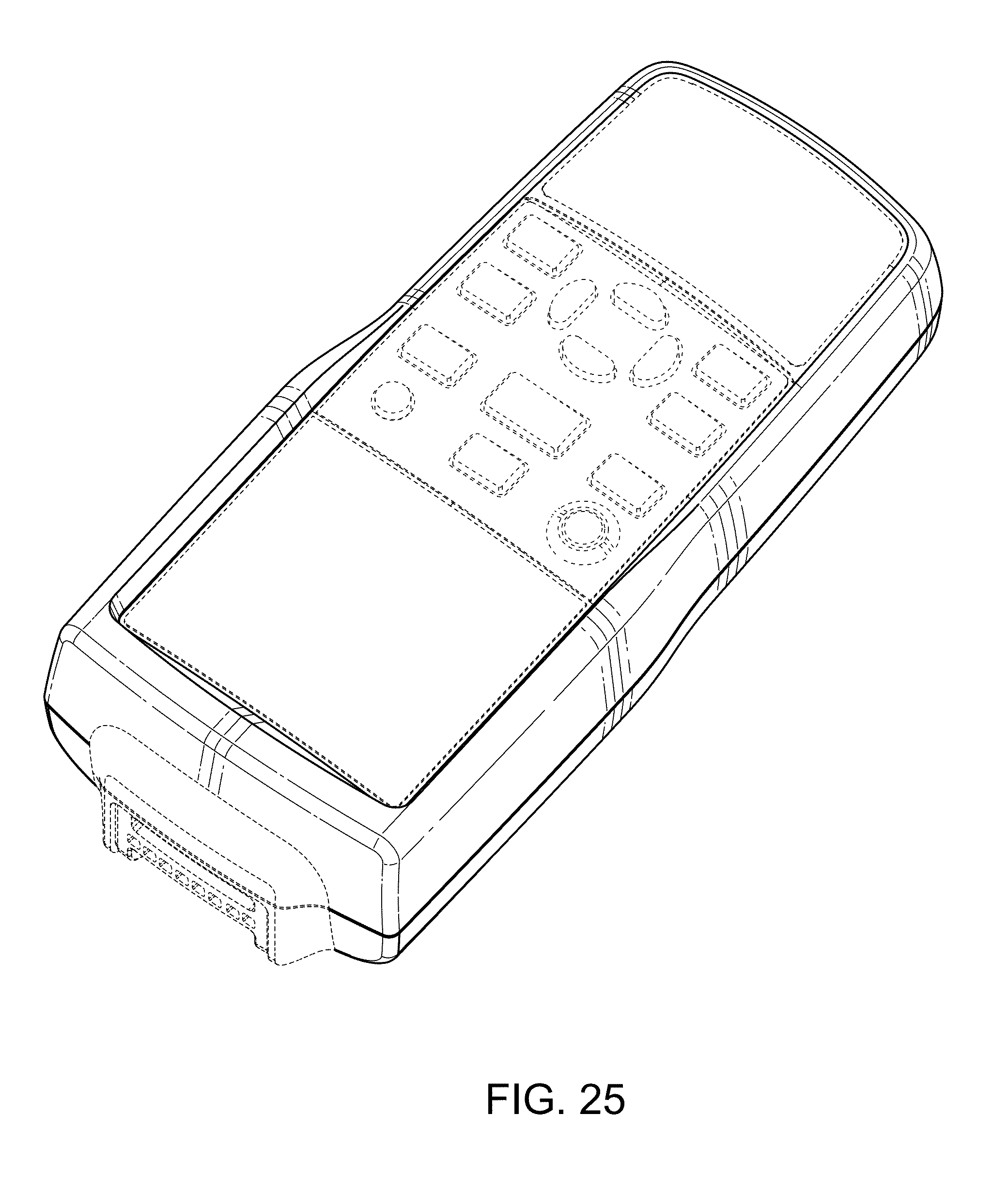
FIG. 25 is a front perspective view of a fourth embodiment of a calibrator case.
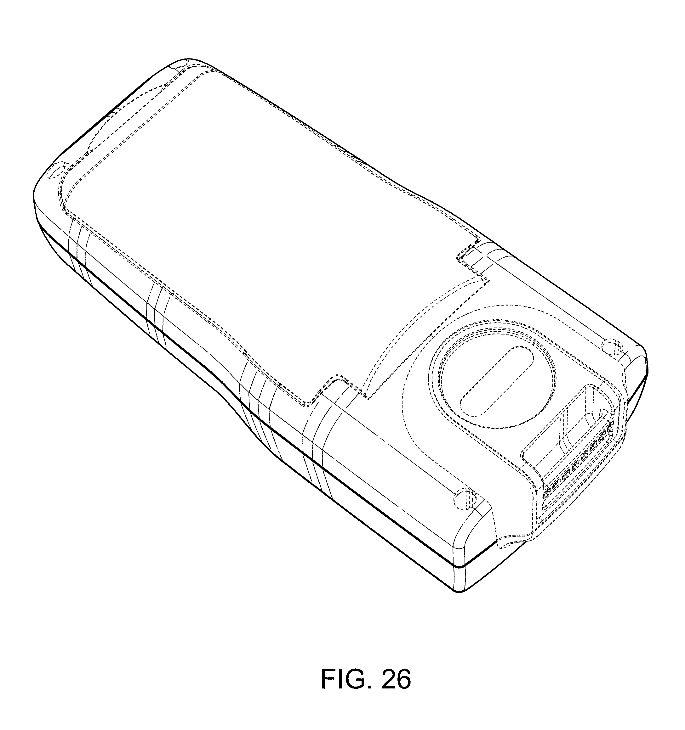
FIG. 26 is a back perspective view thereof.
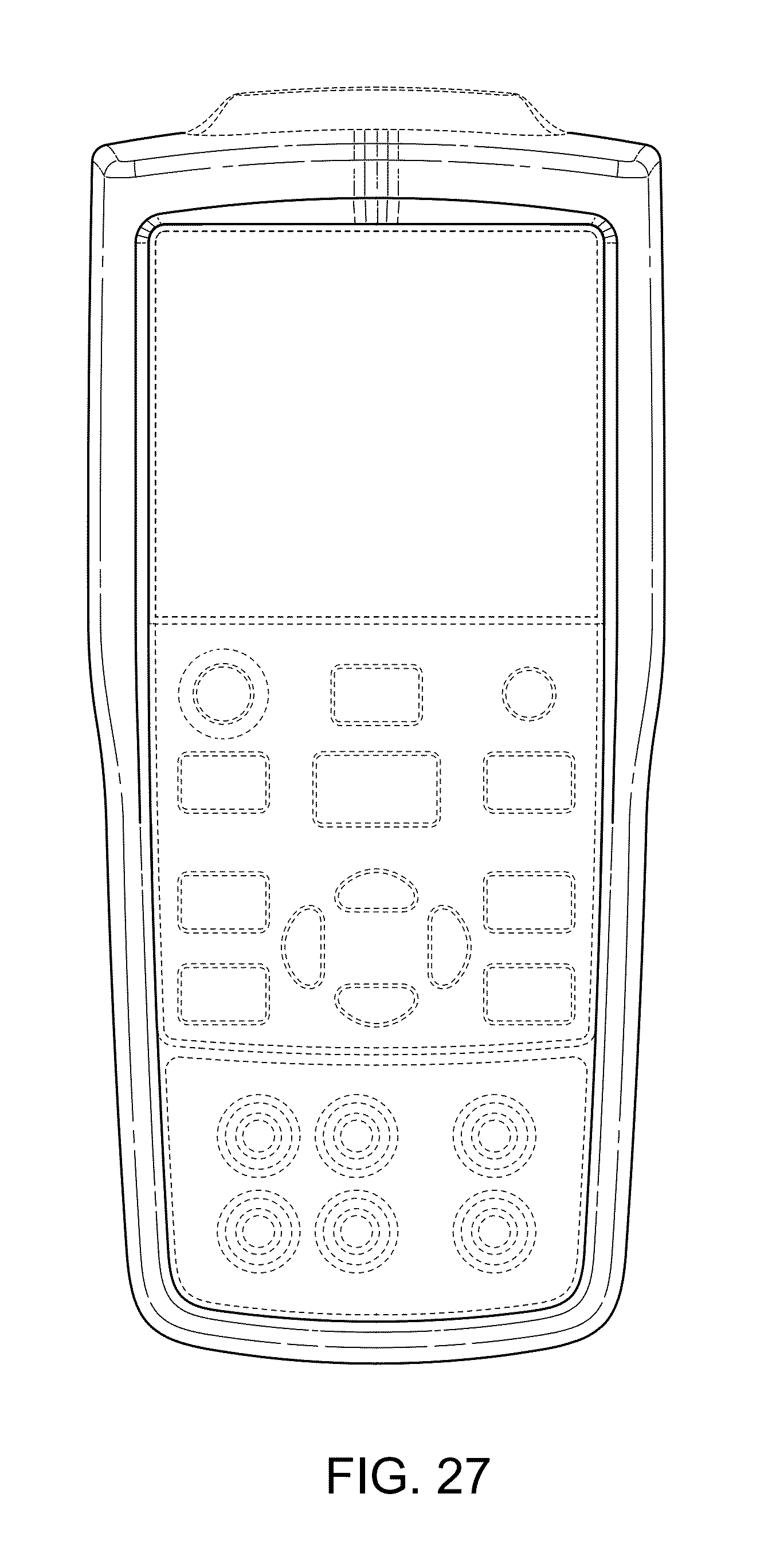
FIG. 27 is a front plan view thereof.
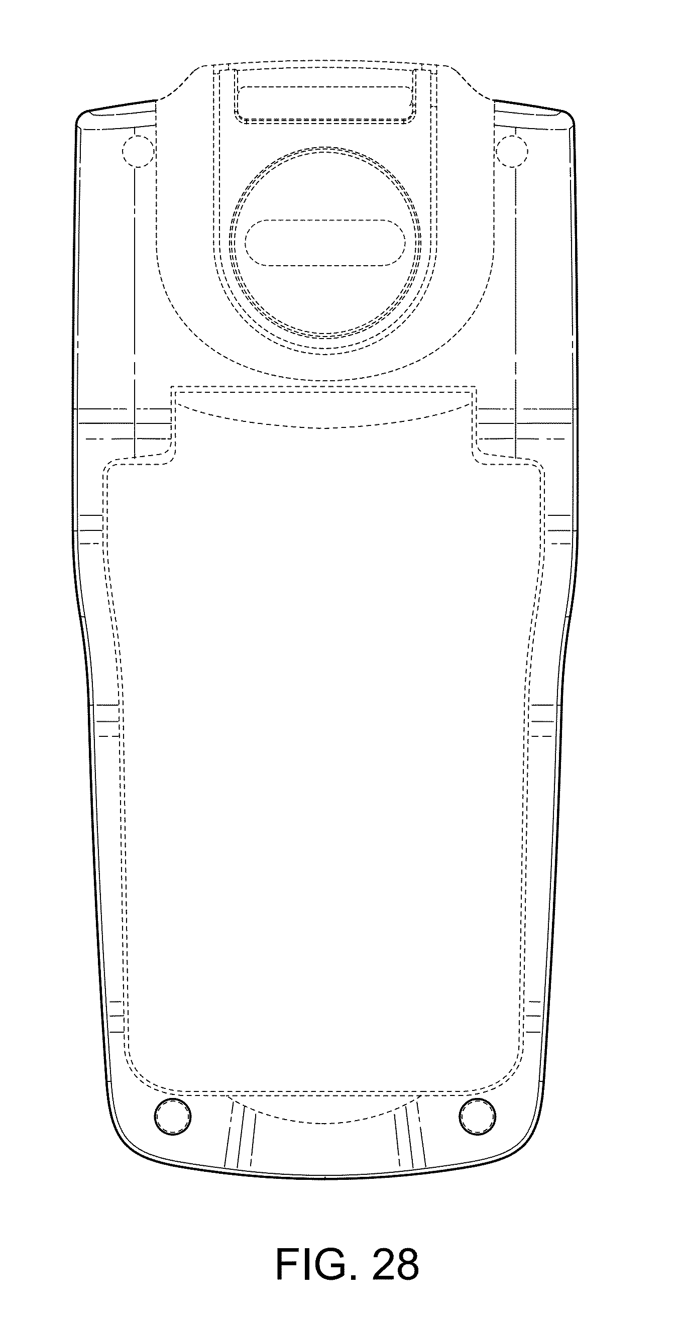
FIG. 28 is a back plan view thereof.
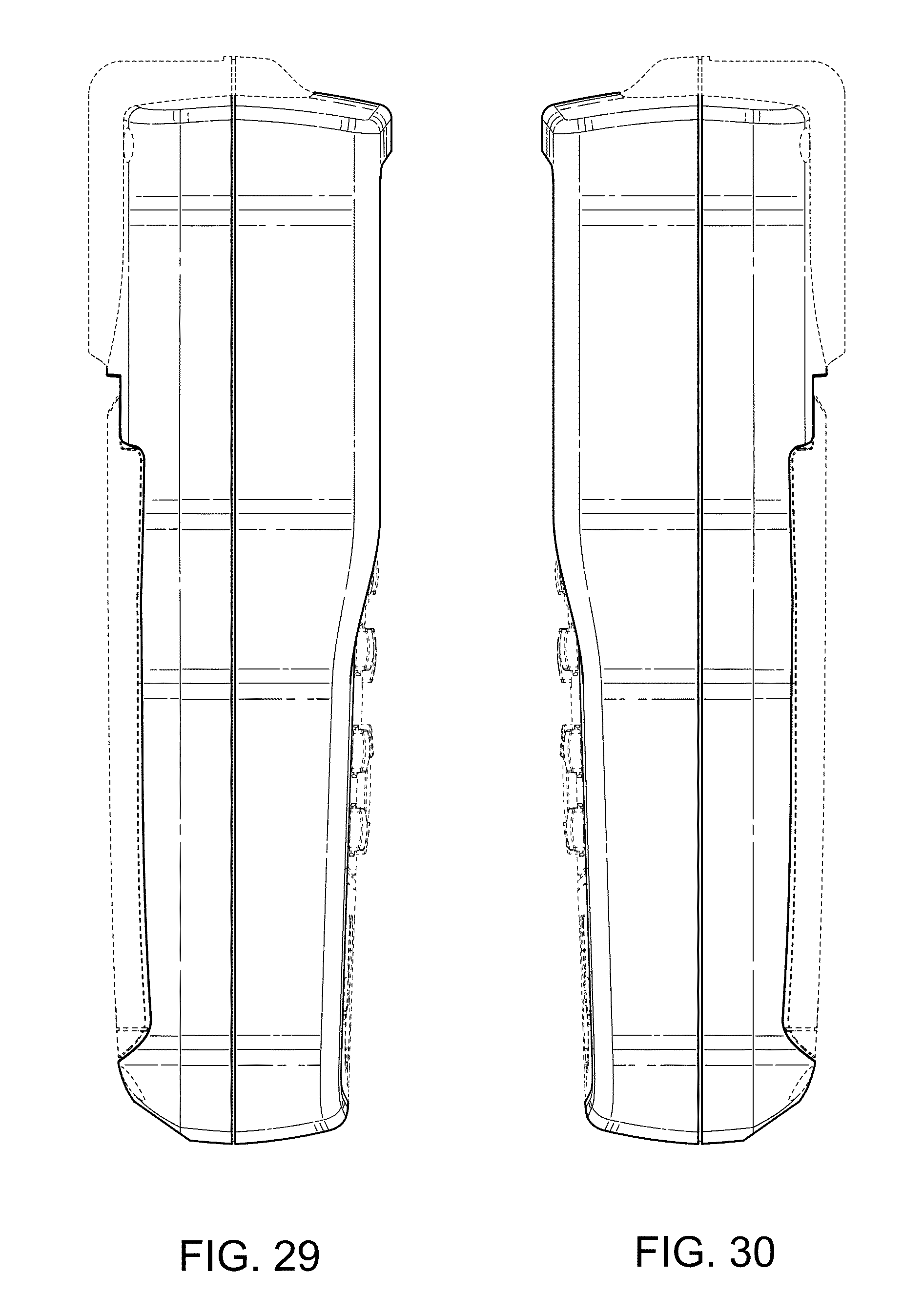
FIG. 29 is a left view thereof.
FIG. 30 is a right view thereof.
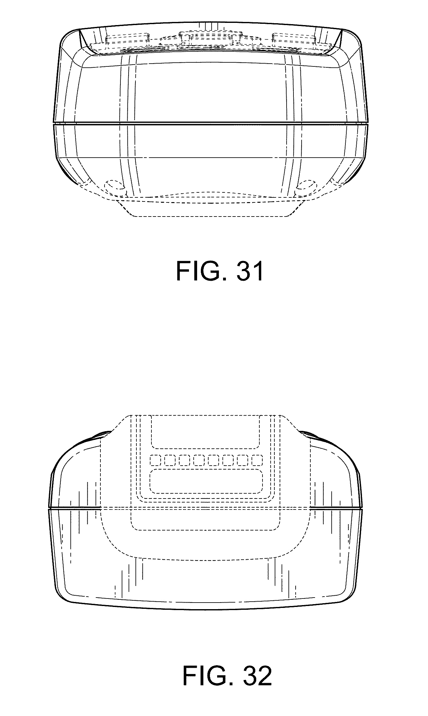
FIG. 31 is a bottom view thereof; and,
FIG. 32 is a top view thereof.
The broken lines form no part of the claimed design.
* * * * *
D00000
D00001
D00002
D00003
D00004
D00005
D00006
D00007
D00008
D00009
D00010
D00011
D00012
D00013
D00014
D00015
D00016
D00017
D00018
D00019
D00020
D00021
D00022
D00023
D00024
XML
uspto.report is an independent third-party trademark research tool that is not affiliated, endorsed, or sponsored by the United States Patent and Trademark Office (USPTO) or any other governmental organization. The information provided by uspto.report is based on publicly available data at the time of writing and is intended for informational purposes only.
While we strive to provide accurate and up-to-date information, we do not guarantee the accuracy, completeness, reliability, or suitability of the information displayed on this site. The use of this site is at your own risk. Any reliance you place on such information is therefore strictly at your own risk.
All official trademark data, including owner information, should be verified by visiting the official USPTO website at www.uspto.gov. This site is not intended to replace professional legal advice and should not be used as a substitute for consulting with a legal professional who is knowledgeable about trademark law.