Data communication device
Okajima , et al.
U.S. patent number D883,978 [Application Number D/648,854] was granted by the patent office on 2020-05-12 for data communication device. This patent grant is currently assigned to CKD CORPORATION. The grantee listed for this patent is CKD CORPORATION. Invention is credited to Hiroaki Banno, Atsushi Fukuta, Hisashi Hatano, Sho Honda, Mitsuhiro Kosugi, Naoki Okajima.
| United States Patent | D883,978 |
| Okajima , et al. | May 12, 2020 |
Data communication device
Claims
CLAIM The ornamental design for a data communication device, as shown and described.
| Inventors: | Okajima; Naoki (Komaki, JP), Banno; Hiroaki (Komaki, JP), Honda; Sho (Komaki, JP), Fukuta; Atsushi (Komaki, JP), Kosugi; Mitsuhiro (Komaki, JP), Hatano; Hisashi (Komaki, JP) | ||||||||||
|---|---|---|---|---|---|---|---|---|---|---|---|
| Applicant: |
|
||||||||||
| Assignee: | CKD CORPORATION (Aichi,
JP) |
||||||||||
| Appl. No.: | D/648,854 | ||||||||||
| Filed: | May 24, 2018 |
Foreign Application Priority Data
| Nov 28, 2017 [JP] | 2017-026380 | |||
| Current U.S. Class: | D14/358 |
| Current International Class: | 1402 |
| Field of Search: | ;D13/146,147,151,154,159,182,184,199 ;D14/299,300,348,356,433,438,439,474,480.1,483,484.1,489,490,492,496,511,358 ;D15/138 |
References Cited [Referenced By]
U.S. Patent Documents
| D562247 | February 2008 | Matsuzaki |
| D562248 | February 2008 | Howerton |
| D562249 | February 2008 | Howerton |
| D563881 | March 2008 | Howerton |
| D563882 | March 2008 | Howerton |
| D669073 | October 2012 | Wu |
| D725098 | March 2015 | Neumann |
| D725099 | March 2015 | Neumann |
| D751987 | March 2016 | Ravi |
| D753796 | April 2016 | Suematsu |
| D753797 | April 2016 | Suematsu |
| D753798 | April 2016 | Suematsu |
| D780295 | February 2017 | Fujita |
| D782612 | March 2017 | Fujita |
| D798822 | October 2017 | Jiang |
| D802582 | November 2017 | Krivonak |
| D809492 | February 2018 | Moon |
| D810078 | February 2018 | Kikuchi |
| D825472 | August 2018 | Yamanaka |
| D828838 | September 2018 | Morris |
| D837017 | January 2019 | Miller |
| 2018/0055172 | March 2018 | Shuto |
Assistant Examiner: Butac; Fritzgerald L
Attorney, Agent or Firm: Cantor Colburn LLP
Description
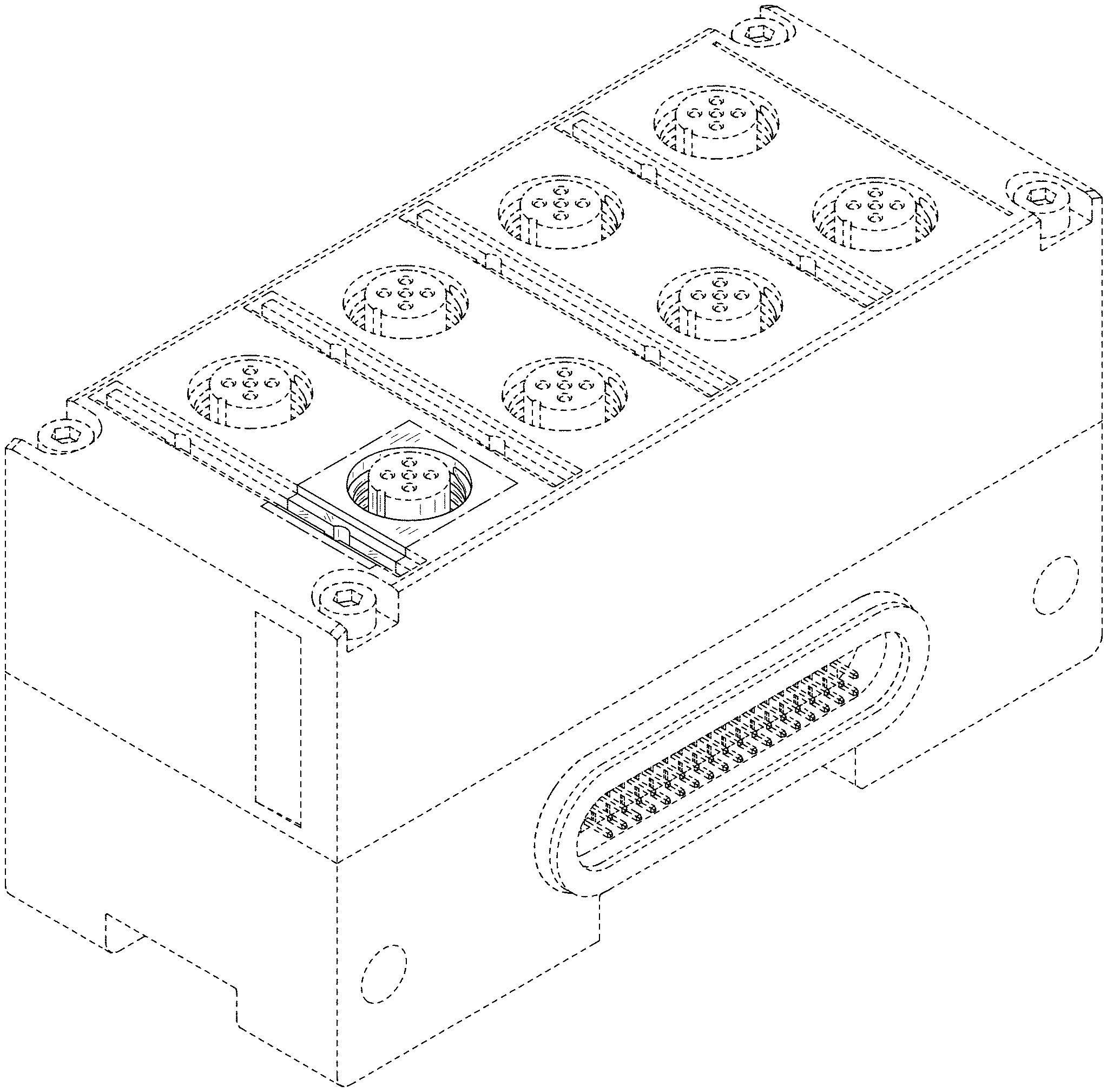
FIG. 1 is a from, top and right side perspective view of a data communication device showing our new design;
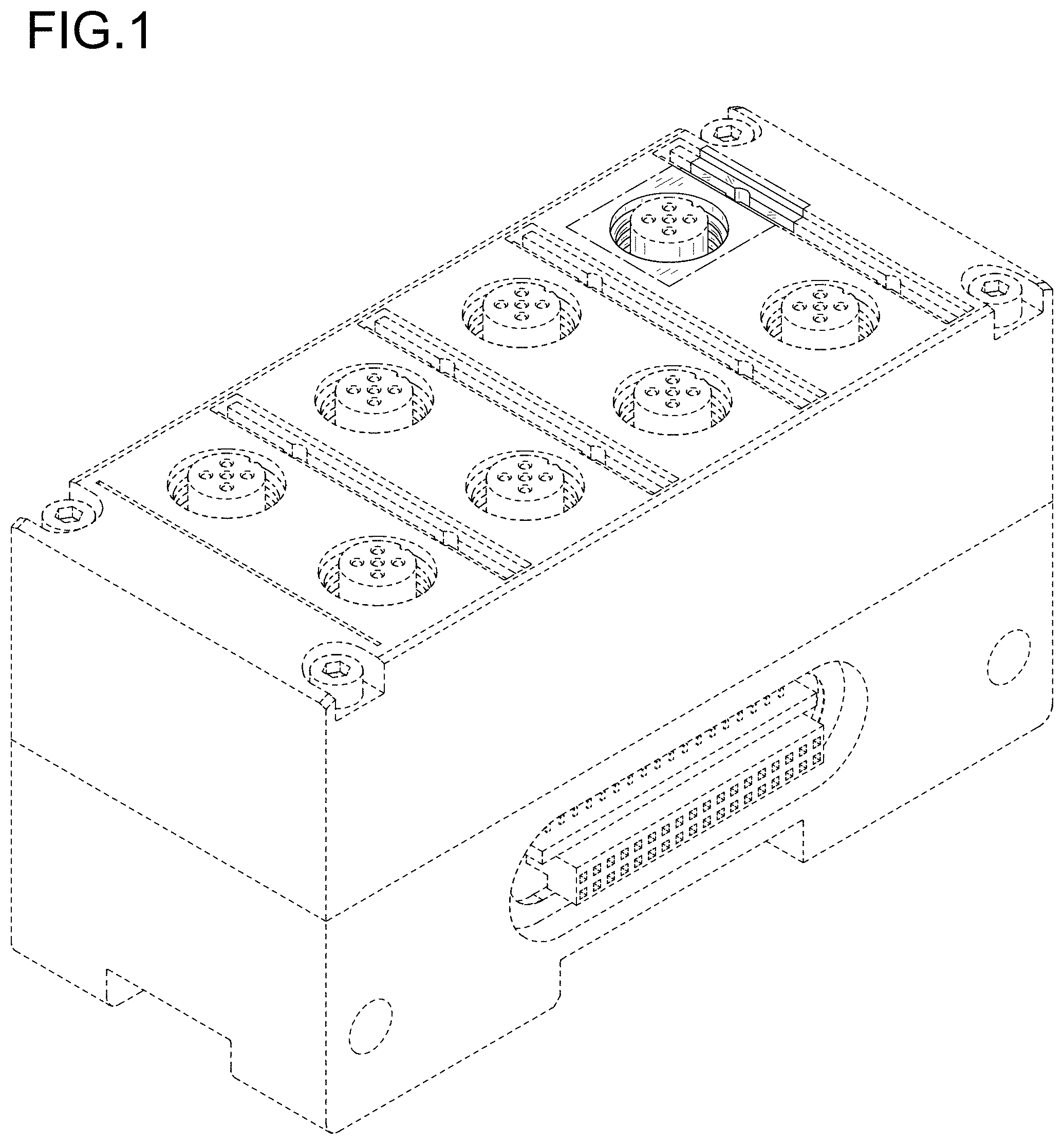
FIG. 2 is a rear, top and left side perspective view thereof;
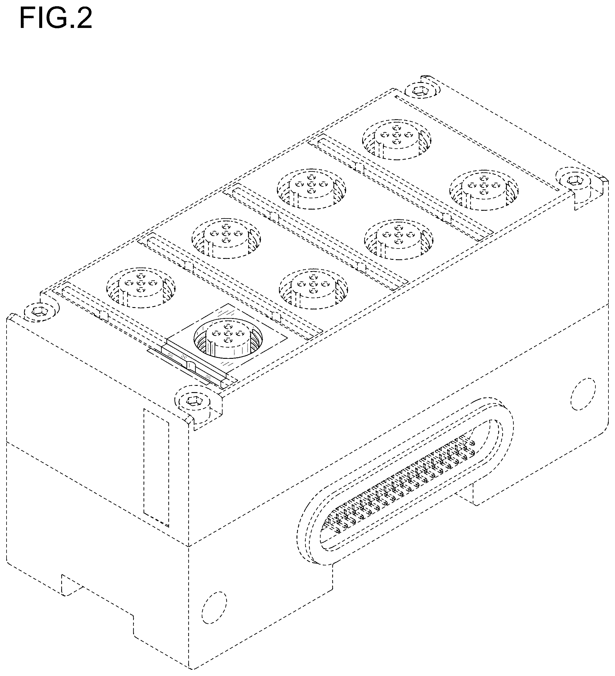
FIG. 3 is a front view thereof;
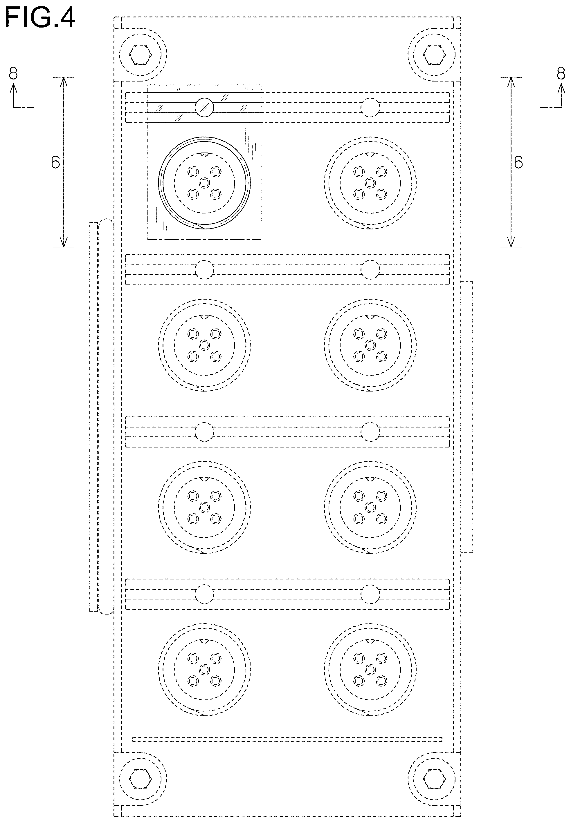
FIG. 4 is a top plan view thereof;
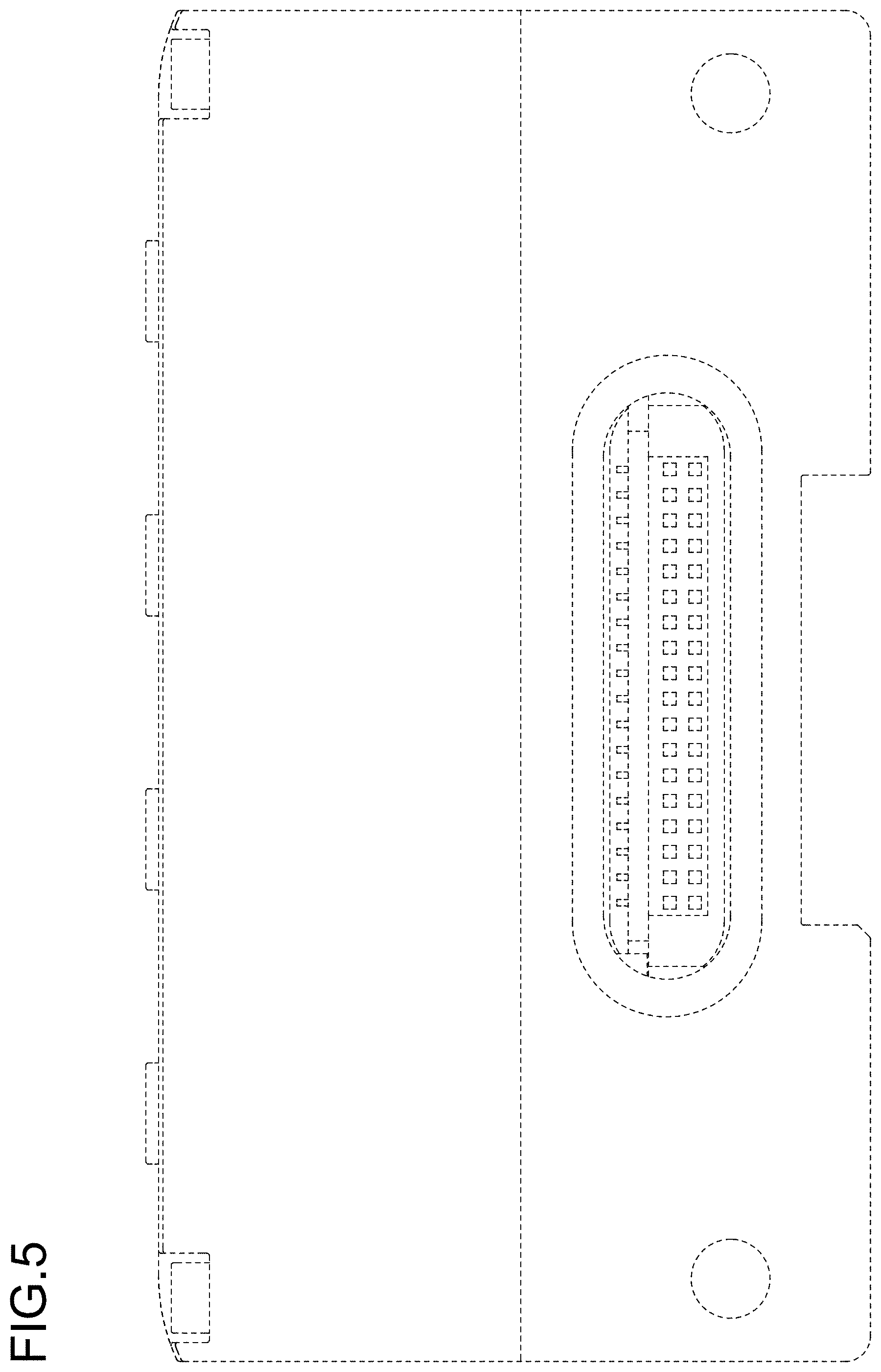
FIG. 5 is a right side view thereof;
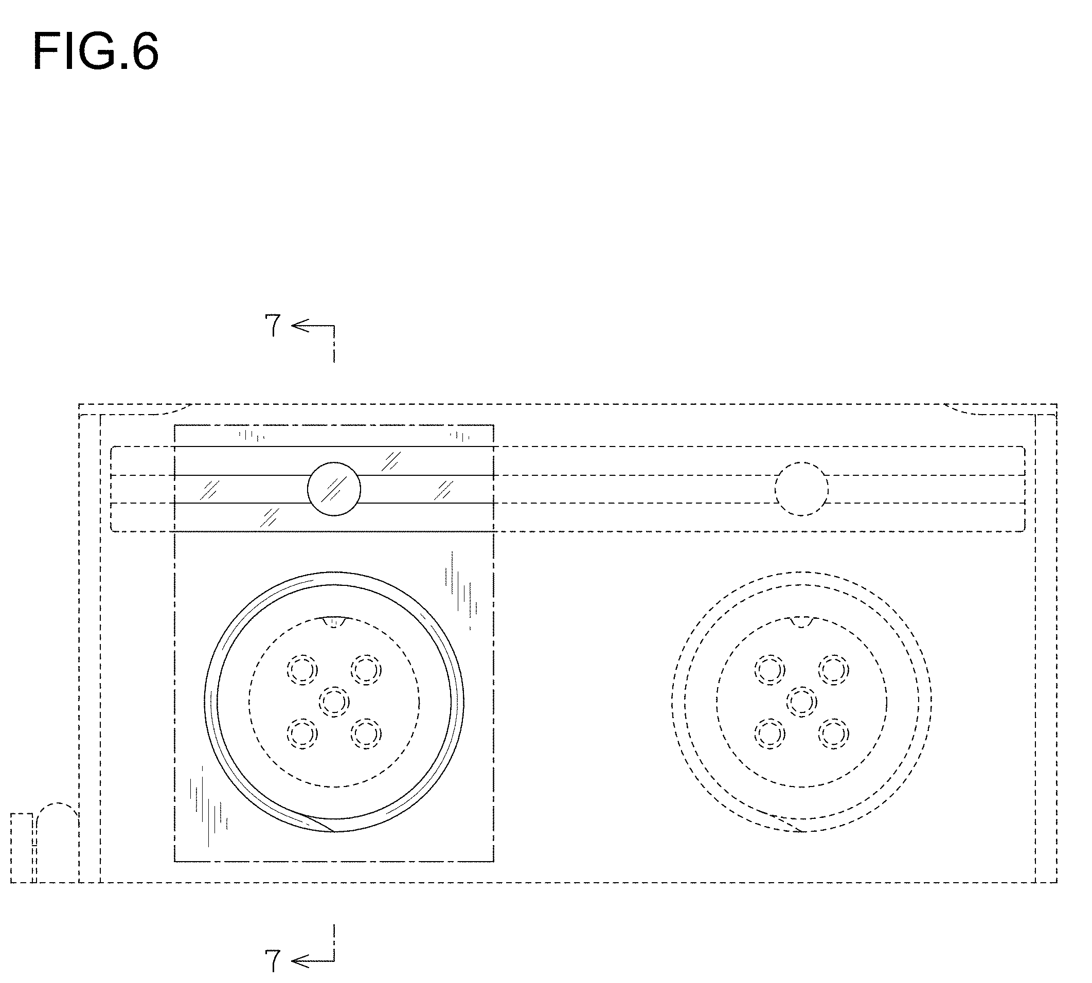
FIG. 6 is an enlarged view showing a portion defined by 6-6 in FIG. 4;
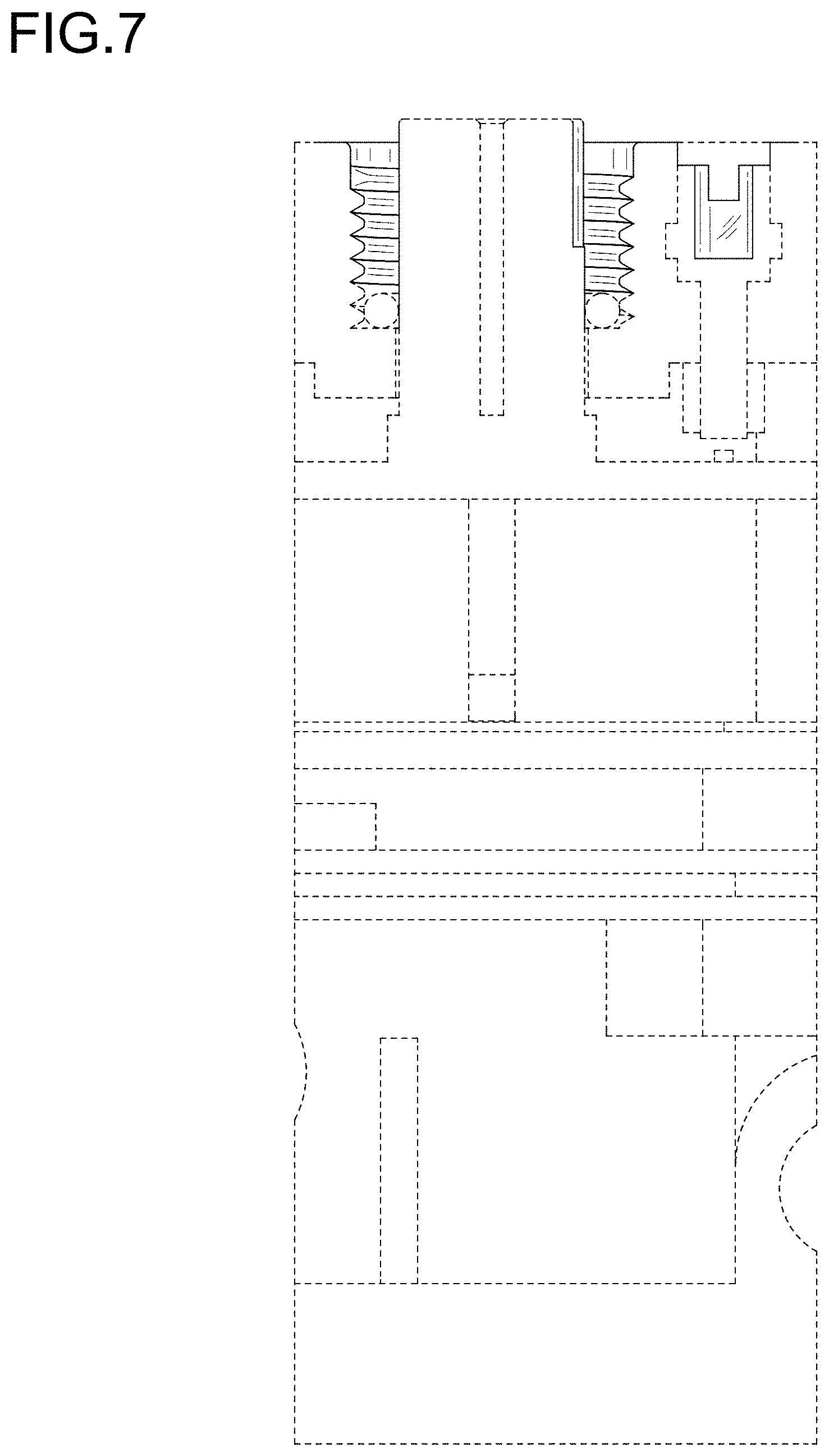
FIG. 7 is a cross-sectional view taken along line 7-7 in FIG. 6; and,
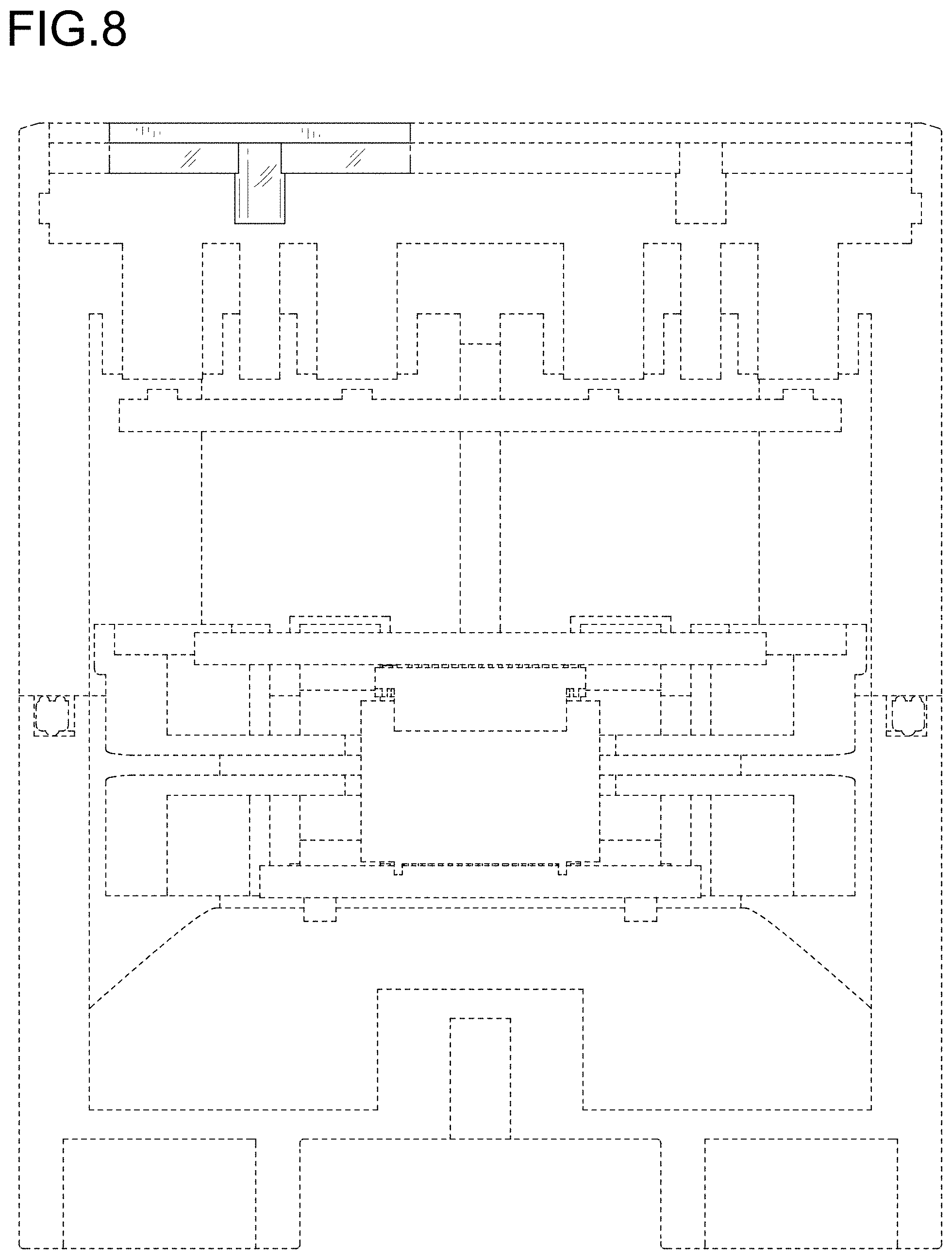
FIG. 8 is a cross-sectional view taken along line 8-8 in FIG. 4.
The broken lines illustrate portions of a data communication device and form no part of the claimed design. The dash-dot lines define the bounds of the claim and form no part of the claimed design.
* * * * *
D00000
D00001
D00002
D00003
D00004
D00005
D00006
D00007
D00008
XML
uspto.report is an independent third-party trademark research tool that is not affiliated, endorsed, or sponsored by the United States Patent and Trademark Office (USPTO) or any other governmental organization. The information provided by uspto.report is based on publicly available data at the time of writing and is intended for informational purposes only.
While we strive to provide accurate and up-to-date information, we do not guarantee the accuracy, completeness, reliability, or suitability of the information displayed on this site. The use of this site is at your own risk. Any reliance you place on such information is therefore strictly at your own risk.
All official trademark data, including owner information, should be verified by visiting the official USPTO website at www.uspto.gov. This site is not intended to replace professional legal advice and should not be used as a substitute for consulting with a legal professional who is knowledgeable about trademark law.