Seismic acquisition system including a distributed sensor having an optical fiber
Kragh , et al. December 30, 2
U.S. patent number 8,924,158 [Application Number 12/853,057] was granted by the patent office on 2014-12-30 for seismic acquisition system including a distributed sensor having an optical fiber. This patent grant is currently assigned to Schlumberger Technology Corporation. The grantee listed for this patent is Arthur H. Hartog, Ed Kragh, Douglas E. Miller, Everhard Muyzert, Johan Robertsson. Invention is credited to Arthur H. Hartog, Ed Kragh, Douglas E. Miller, Everhard Muyzert, Johan Robertsson.

| United States Patent | 8,924,158 |
| Kragh , et al. | December 30, 2014 |
Seismic acquisition system including a distributed sensor having an optical fiber
Abstract
A seismic acquisition system includes a distributed optical sensor (having an optical fiber) and an interrogation subsystem configured to generate a light signal to emit into the optical fiber. The interrogation subsystem receives, from the distributed optical sensor, backscattered light responsive to the emitted light signal, wherein the backscattered light is affected by one or both of seismic signals reflected from a subterranean structure and noise. Output data corresponding to the backscattered light is provided to a processing subsystem to determine a characteristic of the subterranean structure.
| Inventors: | Kragh; Ed (Essex, GB), Muyzert; Everhard (Girton, GB), Robertsson; Johan (Grantchester, GB), Miller; Douglas E. (Boston, MA), Hartog; Arthur H. (Winchester, GB) | ||||||||||
|---|---|---|---|---|---|---|---|---|---|---|---|
| Applicant: |
|
||||||||||
| Assignee: | Schlumberger Technology
Corporation (Sugar Land, TX) |
||||||||||
| Family ID: | 45556750 | ||||||||||
| Appl. No.: | 12/853,057 | ||||||||||
| Filed: | August 9, 2010 |
Prior Publication Data
| Document Identifier | Publication Date | |
|---|---|---|
| US 20120035854 A1 | Feb 9, 2012 | |
| Current U.S. Class: | 702/17 |
| Current CPC Class: | E21B 47/0224 (20200501); G01V 8/00 (20130101); G01V 1/00 (20130101); G01H 9/004 (20130101); G01V 1/3808 (20130101); E21B 49/087 (20130101); G01V 1/003 (20130101); G01D 5/35358 (20130101); G01V 1/36 (20130101) |
| Current International Class: | G01V 1/18 (20060101) |
| Field of Search: | ;702/17 ;367/52,64 |
References Cited [Referenced By]
U.S. Patent Documents
| 602422 | April 1898 | Batcheller |
| 2432378 | December 1947 | Burton |
| 4319347 | March 1982 | Savit |
| 4524436 | June 1985 | Hall et al. |
| 4547869 | October 1985 | Savit |
| 4648082 | March 1987 | Savit |
| 4737106 | April 1988 | Laciny |
| 4805726 | February 1989 | Taylor et al. |
| 4992990 | February 1991 | Langeland et al. |
| 5194847 | March 1993 | Taylor et al. |
| 5597042 | January 1997 | Tubel et al. |
| 5668775 | September 1997 | Hatteland |
| 5790472 | August 1998 | Workman et al. |
| 5892860 | April 1999 | Maron et al. |
| 6205263 | March 2001 | Lieberman et al. |
| 6246048 | June 2001 | Ramos et al. |
| RE37283 | July 2001 | Kluth et al. |
| 6256090 | July 2001 | Chen et al. |
| 6268911 | July 2001 | Tubel et al. |
| 6496261 | December 2002 | Wilsher et al. |
| 6510104 | January 2003 | Ikegami |
| 6555807 | April 2003 | Clayton et al. |
| 6588266 | July 2003 | Tubel et al. |
| 6590647 | July 2003 | Stephenson |
| 6590831 | July 2003 | Bennett et al. |
| 6644402 | November 2003 | Sharma et al. |
| 6722437 | April 2004 | Vercaemer et al. |
| 6724319 | April 2004 | Knaack et al. |
| 6725924 | April 2004 | Davidson et al. |
| 6728165 | April 2004 | Roscigno et al. |
| 6758272 | July 2004 | Bixenman et al. |
| 6772836 | August 2004 | Schetky et al. |
| 6789621 | September 2004 | Wetzel et al. |
| 6837310 | January 2005 | Martin |
| 6839302 | January 2005 | Austad et al. |
| 6874361 | April 2005 | Meltz et al. |
| 6913079 | July 2005 | Tubel |
| 6939717 | September 2005 | Jiang et al. |
| 6977367 | December 2005 | Tubel et al. |
| 7021388 | April 2006 | Williams |
| 7055604 | June 2006 | Jee et al. |
| 7147060 | December 2006 | Huber et al. |
| 7187620 | March 2007 | Nutt et al. |
| 7240730 | July 2007 | Williams et al. |
| 7243715 | July 2007 | Wang et al. |
| 7261162 | August 2007 | Deans et al. |
| 7301474 | November 2007 | Zimmerman |
| 7304725 | December 2007 | Hartog et al. |
| 7308941 | December 2007 | Rolovic et al. |
| 7357021 | April 2008 | Blacklaw |
| 7366055 | April 2008 | Ronnekleiv et al. |
| 7412117 | August 2008 | Chen et al. |
| 7413011 | August 2008 | Chee et al. |
| 7420475 | September 2008 | Adnan et al. |
| 7430903 | October 2008 | Ramos |
| 7451812 | November 2008 | Cooper et al. |
| 7558155 | July 2009 | Ronnekleiv et al. |
| 7586617 | September 2009 | Hartog et al. |
| 7597142 | October 2009 | Hartog et al. |
| 7660496 | February 2010 | Roberts |
| 7668411 | February 2010 | Davies et al. |
| 7848645 | December 2010 | Healey et al. |
| 7946341 | May 2011 | Hartog et al. |
| 8050139 | November 2011 | Berstad |
| 8326540 | December 2012 | Hull et al. |
| 2001/0023614 | September 2001 | Tubel et al. |
| 2002/0066309 | June 2002 | Tubel et al. |
| 2002/0196993 | December 2002 | Schroeder |
| 2003/0033866 | February 2003 | Diakonov et al. |
| 2003/0094281 | May 2003 | Tubel |
| 2003/0205083 | November 2003 | Tubel et al. |
| 2004/0011950 | January 2004 | Harkins |
| 2004/0013040 | January 2004 | Maas et al. |
| 2004/0114849 | June 2004 | Shah et al. |
| 2005/0012036 | January 2005 | Tubel et al. |
| 2005/0140966 | June 2005 | Yamate et al. |
| 2005/0149264 | July 2005 | Tarvin et al. |
| 2005/0180263 | August 2005 | Lambert et al. |
| 2005/0224229 | October 2005 | Blacklaw |
| 2005/0283276 | December 2005 | Prescott et al. |
| 2006/0010973 | January 2006 | Brown |
| 2006/0066839 | March 2006 | Payton |
| 2006/0115204 | June 2006 | Marsh et al. |
| 2006/0165344 | July 2006 | Mendez et al. |
| 2006/0207764 | September 2006 | Rytlewski |
| 2006/0215489 | September 2006 | Solheim et al. |
| 2006/0225507 | October 2006 | Paulson |
| 2006/0225881 | October 2006 | O'Shaughnessy et al. |
| 2007/0126594 | June 2007 | Atkinson et al. |
| 2007/0199696 | August 2007 | Walford |
| 2007/0227727 | October 2007 | Patel et al. |
| 2007/0252717 | November 2007 | Fielder |
| 2007/0263488 | November 2007 | Clark |
| 2007/0265786 | November 2007 | Ozdemir et al. |
| 2008/0030714 | February 2008 | Hall et al. |
| 2008/0042869 | February 2008 | Zimmerman |
| 2008/0134775 | June 2008 | Pipchuk et al. |
| 2008/0139412 | June 2008 | Fuller |
| 2008/0142212 | June 2008 | Hartog et al. |
| 2008/0212917 | September 2008 | Chen |
| 2008/0217022 | September 2008 | Deans |
| 2008/0262737 | October 2008 | Thigpen et al. |
| 2008/0278711 | November 2008 | Sikora |
| 2008/0297772 | December 2008 | Rogers et al. |
| 2008/0314142 | December 2008 | Davies |
| 2009/0006005 | January 2009 | Segal et al. |
| 2009/0008078 | January 2009 | Patel |
| 2009/0037111 | February 2009 | Radtke et al. |
| 2009/0067776 | March 2009 | Ramos et al. |
| 2009/0114386 | May 2009 | Hartog et al. |
| 2009/0122319 | May 2009 | Ronnekleiv et al. |
| 2009/0132183 | May 2009 | Hartog et al. |
| 2009/0182509 | July 2009 | Kimminau et al. |
| 2009/0242197 | October 2009 | Hackworth et al. |
| 2009/0251991 | October 2009 | Ayela et al. |
| 2009/0304322 | December 2009 | Davies et al. |
| 2009/0323075 | December 2009 | Brady |
| 2009/0326826 | December 2009 | Hull et al. |
| 2010/0092176 | April 2010 | Hartog et al. |
| 2010/0107754 | May 2010 | Hartog et al. |
| 2010/0117830 | May 2010 | Strong et al. |
| 2010/0207019 | August 2010 | Hartog et al. |
| 2010/0278010 | November 2010 | Gubin et al. |
| 2010/0313659 | December 2010 | Berg et al. |
| 2011/0292763 | December 2011 | Coates et al. |
| 2012/0020184 | January 2012 | Wilson et al. |
| 2013/0167628 | July 2013 | Hull et al. |
| 0222666 | Sep 1991 | EP | |||
| 1096272 | May 2001 | EP | |||
| 1672344 | Aug 2008 | EP | |||
| 2072986 | Jun 2009 | EP | |||
| 2126820 | Mar 1984 | GB | |||
| 2222247 | Feb 1990 | GB | |||
| 2381281 | Apr 2003 | GB | |||
| 2392462 | Mar 2004 | GB | |||
| 2416398 | Jan 2006 | GB | |||
| 2438432 | Nov 2007 | GB | |||
| 2438533 | Nov 2007 | GB | |||
| 2440351 | Jan 2008 | GB | |||
| 2440956 | Feb 2008 | GB | |||
| 2443051 | Apr 2008 | GB | |||
| 2447691 | Sep 2008 | GB | |||
| 2451162 | Jan 2009 | GB | |||
| 2456300 | Jul 2009 | GB | |||
| 2457278 | Aug 2009 | GB | |||
| 2461191 | Feb 2012 | GB | |||
| 2009020003 | Jan 2009 | JP | |||
| 03050385 | Jun 2003 | WO | |||
| 03050385 | Oct 2003 | WO | |||
| 2005103437 | Nov 2005 | WO | |||
| 2006048647 | Nov 2006 | WO | |||
| 2007072173 | Jun 2007 | WO | |||
| 2007104915 | Sep 2007 | WO | |||
| 2008098380 | Aug 2008 | WO | |||
| 2009056855 | May 2009 | WO | |||
| 2009100087 | Aug 2009 | WO | |||
| 2010/053931 | May 2010 | WO | |||
Other References
|
Dakin, J.P. and P.B. Withers, The reduction of semiconductor laser phase noise for sensor applications. Optica Acta, 1986 33(4) p. 489-499. cited by applicant . Cranch, G.A. and P. J. Nash, High-responsivity fiber-optic flexural disk accelerometers. Journal of Lightwave Technology, 2000 18(9); p. 1233-1243. cited by applicant . Giallorenzi, T., et al. Optical fiber sensor technology. Quantum Electronics, IEEE Journal of 1982. 18(4); p. 626-665. cited by applicant . Alcudia, A. et al., "Microphone experiments and applications in exploration seismology", SEG, Expanded Abstracts, 27, No. 1, 2008, pp. 188-192. cited by applicant . Bakulin, et al., "Real-time completion monitoring with acoustic waves", Geophysics, vol. 73, No. 1, Dec. 26, 2007, pp. 15-33. cited by applicant . Bakulin, A. et al., "Acoustic Surveillance of Production Impairment with Real-Time Completion Monitoring", SPE International Symposium and Exhibition on Formation Damage Control, Lafayette, Louisiana, 2008, pp. 1-12. cited by applicant . Barnoski, M.K. et al., "Fiber waveguides: a novel technique for investigating attenuation characteristics", Applied Optics, 15(9), 1976, pp. 2112-2115. cited by applicant . Biot, M.A. , "Propagation of Elastic Waves in a Cylindrical Bore Containing a Fluid", Journal of Applied Physics, 23 (9), 1952, pp. 997-1003. cited by applicant . Brown, et al., "Optical Fiber Sensors in Upstream Oil & Gas", SPE 79080--Technology Today Series, Nov. 2002, pp. 63-65. cited by applicant . Davies, Sean, "Passive acoustic monitoring helps protect wildlife", IET Knowledge Network, Aug. 2009, pp. 1-2. cited by applicant . Hartog, A.H. et al., "On the theory of backscattering in single-mode optical fibers", Journal of Lightwave Technology, 2(2), 1984, pp. 76-82. cited by applicant . Healey, P., "Statistics of Rayleigh Backscatter from a Single-Mode Fiber", Communications, IEEE Transaction on [legacy, pre-1988], 35(2), 1987, pp. 210-214. cited by applicant . Hill, K.O., "Photosensitivity in Optical Fiber Waveguides: From Discovery to Commercialization", IEEE Journal of Selected Topics in Quantum Electronics, 6(6), 2000, pp. 1186-1189. cited by applicant . Hughes, R. et al., "Static Pressure Sensitivity Amplification in Interferometric Fiber-Optic Hydrophones", Applied Optics, 19(1), 1980, pp. 98-107. cited by applicant . Juarez, J.C. et al., "Distributed Fiber-Optic Intrusion Sensor System", Journal of Lightwave Technology, 23(6), 2005, pp. 2081-2087. cited by applicant . Juarez, J.C. et al., "Field test of a Distributed Fiber-Optic Intrusion Sensor System for Long Perimeters", Applied Optics, 46(11), 2007, pp. 1968-1971. cited by applicant . Juarez, J.C. et al., "Polarization Discrimination in a Phase-Sensitive Optical time-Domain Reflectometer Intrusion-Sensor System", Optics Letters, 30(24), 2005, pp. 3284-3286. cited by applicant . Juskaitis, R. et al., "Distributed Interferometric Fiber Sensor System", Optics Letters, 17(22), 1992, pp. 1623-1625. cited by applicant . Juskaitis, R. et al., "Interferometry with Rayleigh Backscattering in a Single-Mode Optical Fiber", Optics Letters, 19 (3), 1994, p. 225. cited by applicant . Kirkendall, C., "Distributed Acoustic and Seismic Sensing", IEEE Optical Fiber Communications Conference and Exposition Fiber Optic Engineers Conference, Mar. 2007, pp. 1-3. cited by applicant . Kirkendall, C.K. et al., "Overview of High Performance Fibre-Optic Sensing", Journal of Physics D: Applied Physics, 37, 2004, pp. R197-R216. cited by applicant . Liu, et al., "Effects of an Elastic Membrane on Tube Waves in Permeable Formations", The Journal of the Acoustical Society of America, 101(6), 1997, pp. 3322-3329. cited by applicant . Mermelstein, M.D. et al., "Raleigh Scattering Optical Frequency Correlation in a Single-Mode Optical Fiber", Optics Letters, 26(2), 2001, pp. 58-60. cited by applicant . Mickelson, A.R. et al., "Theory of the Backscattering Process in Multimode Optical Fibers", Applied Optics, 21(11), 1982, pp. 1898-1909. cited by applicant . Miller, D. et al., "Implosive Borehole Acoustics", 2006. cited by applicant . Nash, P. , "Review of interferometric optical fibre hydrophone technology", IEEE Proceedings on Radar, Sonar and Navigation, 143(3), 1996, pp. 204-209. cited by applicant . Norris, A.N. , "Stoneley-wave Attenuation and Dispersion in Permeable Formations", Geophysics, 54(3), 1989, pp. 330-341. cited by applicant . Posey, R.J. et al., "Rayleigh Scattering Based Distributed Sensing System for Structural Monitoring", 14th Conference on Optical Fibre Sensors, Venice, Italy, 2001, pp. 678-681. cited by applicant . Posey, R.J. et al., "Strain Sensing Based on Coherent Rayleigh Scattering in the Optical Fibre", Electronics Letter, 36(20), 2000, pp. 1688-1689. cited by applicant . Schoenberg, M. et al., "Attenuation of Acoustic Modes Due to Viscous Drag at the Borehole Wall", Geophysics, 52 (11), 1987, pp. 1566-1569. cited by applicant . Strong, A. et al., "A comprehensive distributed pipeline condition monitoring system and its field trial", 7th International Pipeline Conference, vol. 1, 2008, pp. 711-719. cited by applicant . Winbow, G.A. , "Seismic Sources in Open and Cased Boreholes", Geophysics, 56(7), 1991, pp. 1040-1050. cited by applicant. |
Primary Examiner: Teixeira Moffat; Jonathan C
Assistant Examiner: Betsch; Regis
Attorney, Agent or Firm: Clark; Brandon S.
Claims
What is claimed is:
1. A seismic acquisition system, comprising: a seismic sensor system to detect seismic signals and seismic noise generated during a survey of a subterranean structure, the seismic sensor system including a distributed optical sensor that comprises a generally continuous length of optical fiber without discrete sensors for positioning outside the subterranean structure for detection of the seismic noise; a processing subsystem; and an interrogation subsystem configured to: generate optical pulses to emit into the generally continuous length of optical fiber, wherein the optical pulses are selected to provide a spatial resolution that is less than a wavelength of the seismic noise; receive, from the distributed optical sensor, backscattered light generated by inhomogeneities at locations extending along the continuous length of optical fiber responsive to the emitted optical pulses, wherein the backscattered light generated by the inhomogeneities is indicative of at least the seismic noise; and output data corresponding to the backscattered light to the processing subsystem to determine a characteristic of the subterranean structure, wherein the output data includes a measurement of the detected seismic noise, wherein the processing subsystem uses the measurement of the detected seismic noise to at least reduce components of seismic noise that are present in the detected seismic signals.
2. The seismic acquisition system of claim 1, wherein the distributed optical sensor is arranged for use in one of land-based seismic surveying and marine seismic surveying.
3. The seismic acquisition system of claim 1, wherein the spatial resolution is less than the wavelength of the seismic signals.
4. The seismic acquisition system of claim 1, wherein the spatial resolution is less than wavelengths of the noise and the seismic signals.
5. The seismic acquisition system of claim 4, wherein both the noise and the seismic signals are sampled in the backscattered light, the seismic acquisition system further comprising: a filter to attenuate the noise represented in the backscattered light.
6. The seismic acquisition system of claim 1, wherein the optical fiber is straight.
7. The seismic acquisition system of claim 1, further comprising a streamer having the distributed optical sensor for towing through a body of water, wherein parts of the streamer have a diameter less than 4 centimeters.
8. The seismic acquisition system of claim 1, wherein the optical fiber is a first optical fiber dedicated to the distributed optical sensor, and the seismic acquisition system further comprises at least another optical fiber having regions of different sensitivities.
9. A method comprising: providing a seismic sensor system to detect seismic signals and seismic noise generated during a survey of a subterranean structure, the seismic sensor system including a distributed optical sensor that comprises a generally continuous length of optical fiber without discrete sensors for positioning outside the subterranean structure to detect at least the seismic noise; detecting the seismic signals; detecting the seismic noise by: emitting optical pulses into the generally continuous length of optical fiber, wherein the optical pulses are selected to provide a spatial resolution that is less than a wavelength of the seismic noise; receiving backscattered light generated by inhomogeneities located along the continuous length of optical fiber responsive to the emitted optical pulses, wherein the backscattered light generated by the inhomogeneities is indicative of at least the seismic noise; and processing, by a processing subsystem, data relating to the backscattered light to determine the seismic noise and use the determined seismic noise to at least reduce components of seismic noise in the detected seismic signals.
10. The method of claim 9, further comprising: providing discrete seismic sensors separate from the distributed optical sensor; receiving seismic data corresponding to the detected seismic signals from the discrete seismic sensors; and using, by the processing subsystem, the data corresponding to the backscattered light to remove seismic noise from the seismic data of the seismic sensors.
11. The method of claim 10, wherein the distributed optical sensor and the seismic sensors are provided as part of a streamer, the method further comprising: towing the streamer through a body of water.
12. The method of claim 10, wherein the distributed optical sensor and the seismic sensors are provided to perform land seismic acquisition.
13. The method of claim 10, wherein the distributed optical sensor and the seismic sensors are provided as part of a seabed cable.
14. The method of claim 9, further comprising: deriving a propagation speed of the noise using the data corresponding to the backscattered light.
Description
BACKGROUND
Subterranean surveying can be used to determine the content of a subterranean structure, which can be underneath a land surface or under a water bottom surface (e.g., seabed). Marine subterranean surveying involves deploying sensors that are towed through a body of water, or deployed on the water bottom surface. Land subterranean surveying involves deploying the sensors on the land surface.
One type of subterranean surveying is seismic subterranean surveying, in which seismic signals generated by seismic sources are propagated into a subterranean structure. The propagated seismic signals are reflected from subterranean elements in the subterranean structure, where the reflected signals are detected by the seismic sensors. The data collected by the seismic sensors are then processed to determine characteristics of the subterranean structure.
SUMMARY
In general, according to some embodiments, a seismic acquisition system includes a distributed sensor having an optical fiber, and an interrogation subsystem to generate a light signal to emit into the optical fiber. The interrogation system receives, from the distributed sensor, backscattered light responsive to the emitted light signal. The backscattered light is affected by one or both of seismic signals reflected from a subterranean structure and noise. Data corresponding to the backscattered light is output to a processing subsystem to determine a characteristic of the subterranean structure.
Other or alternative features will become apparent from the following description, from the drawings, and from the claims.
BRIEF DESCRIPTION OF THE DRAWINGS
Some embodiments are described with respect to the following figures:
FIGS. 1 and 2 are example arrangements for performing seismic subterranean surveying in which some embodiments of the invention can be incorporated;
FIGS. 3 and 4 are schematic diagrams of portions of seismic acquisition structures according to alternative embodiments;
FIG. 5 is a schematic diagram of an arrangement including a distributed optical sensor with an optical fiber and an interrogation system, according to some embodiments;
FIGS. 6-9 illustrate different implementations of distributed optical sensors including optical fibers, according to various embodiments;
FIG. 10 is a flow diagram of a process of performing seismic surveying according to some embodiments.
DETAILED DESCRIPTION
In performing seismic surveys, seismic signals detected by seismic sensors can be contaminated by noise. In a marine environment, the noise can include swell type noise induced from the sea surface and/or noise caused by vibration of components dragged through a body of water. In a land environment, the noise can include trapped energy propagating in the near-surface of the ground, such as ground-roll noise, and/or by energy propagating in the air across the survey area. Conventionally, seismic surveys are typically designed to try to minimize various types of noise, such as by specifying numbers of seismic sensors, spacings between seismic sensors, types of seismic sensors, and/or specific plantings of seismic sensors and seismic sources into a ground surface. Moreover, the hardware design of seismic sensors and/or seismic sources can be configured to attenuate noise.
An issue associated with conventional noise mitigation techniques is that they may be relatively complex, can be expensive, or can be time-consuming to implement.
In accordance with some embodiments, for more efficient noise mitigation when performing seismic surveys, a seismic acquisition system having a distributed optical sensor is provided. The distributed optical sensor includes an elongated optical fiber (or multiple elongated optical fibers). The distributed optical sensor can be used to measure seismic noise in any environment, and the measurement collected by the distributed optical sensor can then be used as a reference for subtracting noise from target seismic signals.
Although reference is made to using the distributed optical sensor to measure seismic noise, it is noted that the distributed optical sensor can also be used to directly measure seismic signals reflected from subterranean elements of a subterranean structure. In such implementations, the distributed optical sensor is used to replace conventional seismic sensors (such as geophones, hydrophones, accelerometers, etc.). In other alternative implementations, the distributed optical sensor can be used in connection with conventional seismic sensors. In some examples, the distributed optical sensor is for positioning outside the subterranean structure (such as above or on a ground surface that is above the subterranean structure).
In response to light signal emitted into the optical fiber of the distributed optical sensor, backscattered light is provided by the distributed optical sensor to an interrogation subsystem. Backscattered light provided by an optical fiber refers to a portion of light reflected by the optical fiber (or reflectors associated with the optical fiber) in a direction opposite to the direction of light emitted into the optical fiber. The backscattered light is affected by one or both of (1) noise in the seismic surveying environment, and (2) seismic signals reflected from a subterranean structure. Data corresponding to the backscattered light is output to a processing subsystem, which can use the data to determine a characteristic of the subterranean structure.
Depending upon the configuration of the seismic acquisition system, the data corresponding to the backscattered light can represent seismic signals with noise attenuated, can represent both seismic signals and noise, or can represent just noise. In some implementations, the seismic acquisition system can include seismic sensors in addition to the distributed optical sensor, with the noise derived from the data corresponding to the backscattered light used to remove the noise component from seismic data collected by the seismic sensors. As noted above, in other implementations, seismic sensors do not have to be used, with the distributed optical sensor used for detecting seismic signals reflected from the subterranean structure.
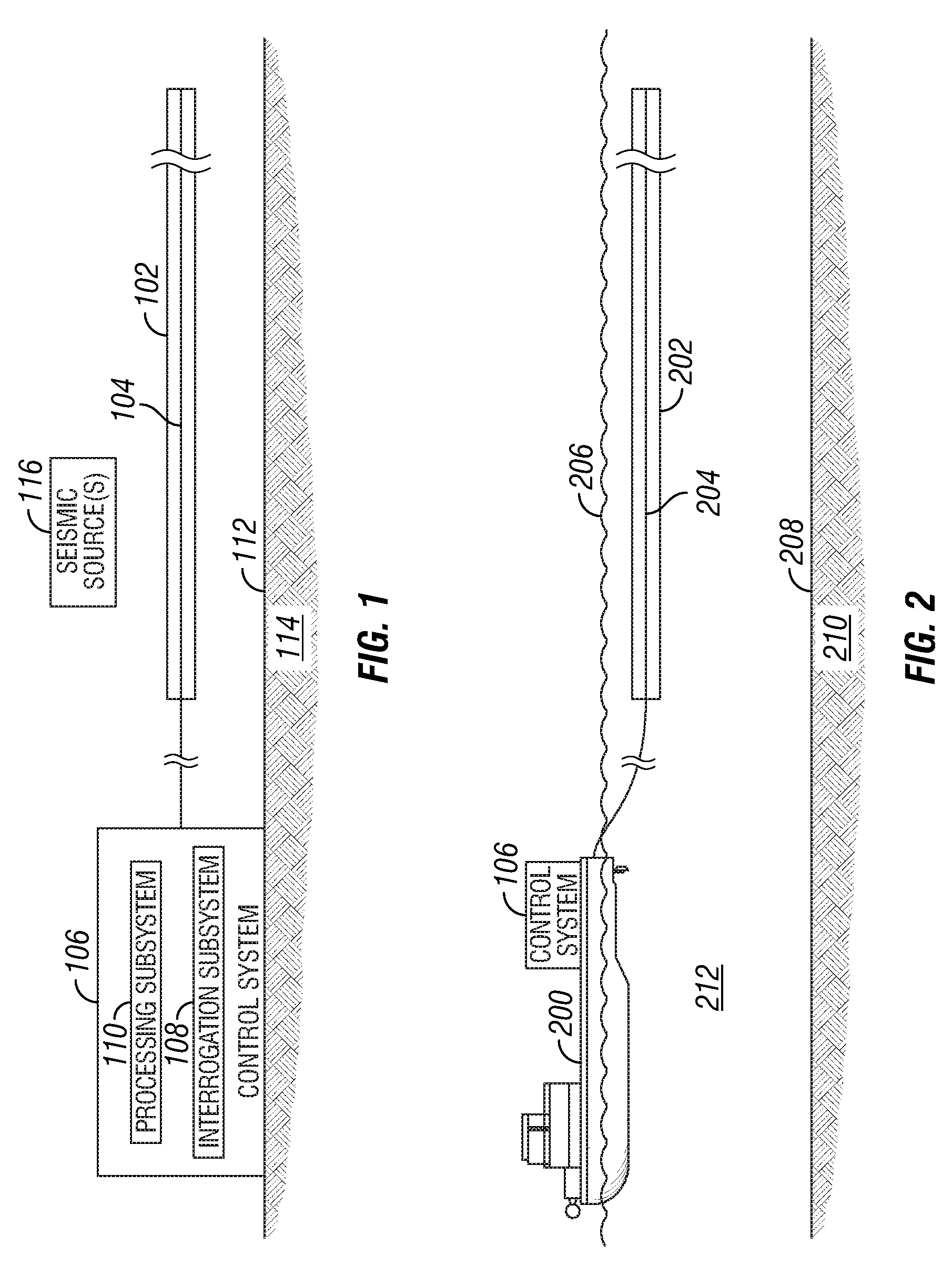
FIG. 1 depicts an example arrangement of a surface seismic acquisition system that includes a distributed optical sensor 102 having an elongated optical fiber 104 (or multiple elongated optical fibers). The optical fiber 104 is connected to a control system 106 that has an interrogation subsystem 108 and a processing subsystem 110. The interrogation subsystem 108 is able to generate light signal for emission into the optical fiber 104. The interrogation subsystem 108 also includes an optical receiver to receive, from the optical fiber 104, backscattered light that is responsive to the emitted light signal.
The distributed optical sensor 102 is provided above a surface 112, underneath which is a subterranean structure 114. One or multiple seismic sources 116 is (are) provided for emitting seismic signals into the subterranean structure 114. The subterranean structure 114 reflects seismic signals back to the surface 112, which can be detected by the distributed optical sensor 102 (or by seismic sensors). As noted above, based on the configuration of the seismic acquisition system, the optical fiber 104 can be used to detect just noise, to detect both seismic signals reflected from the subterranean structure 114 and noise, or to detect seismic signals with noise attenuated. The arrangement shown in FIG. 1 can be used for land seismic surveying. Alternatively, the distributed optical sensor 102 of FIG. 1 can be provided in a cable that is on a water bottom surface (e.g., seabed) to perform marine seismic surveying.
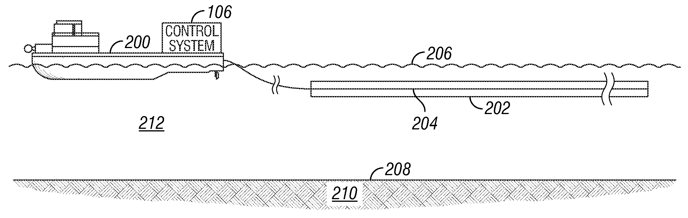
FIG. 2 shows an alternative implementation in which a distributed optical sensor 202 having an optical fiber 204 (or multiple optical fibers) is towed through a body of water 212 underneath a water surface 206. The distributed optical sensor 202 is towed by a marine vessel 200, on which the control system 106 is provided. In some implementations, the distributed optical sensor 202 is part of a streamer that is towed through the body of water 212. Although not shown, one or multiple seismic sources can also be towed by the marine vessel 200 (or by another marine vessel). The seismic source(s) is (are) activated to generate seismic signals that are propagated into a subterranean structure 210 underneath a water bottom surface 208. Reflected seismic signals from the subterranean structure 210 are detected by either the distributed optical sensor 202 having the optical fiber 204, or by seismic sensors (not shown) that are part of the streamer towed by the marine vessel 200.
Alternatively, a marine survey system having a distributed optical sensor can be stationary (or almost stationary) rather than towed at typical tow speeds for seismic surveying. For example, a streamer can be stationary (or almost stationary), or an arrangement of a large number of streamers or optical fibers can be provided that are stationary or almost stationary (towed at relatively slow speeds).
FIGS. 1 and 2 show the distributed optical sensor 102 or 202 without the presence of seismic sensors. FIG. 3 shows alternative implementations in which a seismic acquisition structure 300 includes both an optical fiber 302 as well as seismic sensors 304 (e.g., geophones, hydrophones, accelerometers, etc.). Not shown in FIG. 3 are electrical wires that connect to the seismic sensors 304, in some implementations. In some implementations, some or all of the seismic sensors are optical and are interconnected and connected to the control system 106 by optical fibers rather than electrical wires. The seismic acquisition structure 300 shown in FIG. 3 can be part of a land-based cable, a seabed cable, or a streamer. In operation, the seismic sensors 304 are used to detect seismic signals reflected from a subterranean structure, in response to seismic signals produced by one or more seismic sources. The optical fiber 302, on the other hand, can be used to measure noise, where the noise as measured by the optical fiber 302 can be used to remove noise components from seismic signals detected by the seismic sensors 304.
By using the distributed optical sensor according to some implementations, the diameter of a support structure (e.g., streamer or cable) can be less than 4 cm (centimeters), and more specifically, less than or equal to 1 cm, according to some examples. For example, as shown in FIG. 3, the diameter D of the sections of the seismic acquisition structure 300 corresponding to the optical fibers would be less than the predefined diameter (4 cm or 1 cm).
In some implementations, backscattering of light in response to light emitted into an optical fiber is caused by inhomogeneities of the optical fiber. In other implementations, a distributed optical sensor can be provided with one or multiple regions of different sensitivities along the optical fiber for causing backscattering of light. For example, as shown in FIG. 4, a distributed optical sensor 400 has optical fiber sections 402 having a first sensitivity, and sections 404 having a second sensitivity that is higher than the first sensitivity. In one example, the sections 404 of higher sensitivity can be implemented with fiber optic accelerometers. In alternative implementations, the sections 402 and sections 404 can be optical fiber sections filled with different types of materials to provide different sensitivities. In further alternative implementations, the sections 404 can be discrete optical fiber sensors. A discrete optical fiber sensor, in some examples, can include a length of a sensing fiber that is coiled about and coupled to a transducer. In other implementations, the sections 404 can be implemented with wavelength selected elements, such as fiber Bragg gratings. In implementations according to FIG. 4, backscattering of light is caused by the sections 404 having higher sensitivity than optical fiber sections 402 of the distributed optical sensor 400.
In another implementation, a bundle of multiple fibers is used with one fiber dedicated to the distributed optical sensor and a second fiber having Bragg gratings. Further fibers could be used for discrete optical fiber sensors by coiling the fiber.
FIG. 5 illustrates an interrogation subsystem according to some implementations that can be used with a distributed optical sensor 500 (which can be any of the sensors shown in FIGS. 1-4). The interrogation system 108 includes an optical source 502 that generates an optical signal, such as an optical pulse (or sequence of optical pulses), for interrogating the optical fiber in the distributed sensor 500. In some implementations, the optical source 502 may include a narrow band laser source that is followed by a modulator 504 that selects short pulses from the output of the laser. Optionally, an optical amplifier may be used to boost the peak power of the pulses launched into the optical fiber. The amplifier may be placed after the modulator 502, and the amplifier may also be followed by a filter for filtering in the frequency domain (e.g., bandpass filter) and/or in the time domain.
The pulses emitted by the optical source 502 are launched into the optical fiber of the distributed optical sensor 500 through a directional coupler 506, which separates outgoing and returning optical signals and directs the returning (backscattered) signals to an optical receiver 508. The directional coupler 506 may be a beam splitter, a fiber-optic coupler, a circulator, or some other optical device.
The backscattered optical signals returned from the optical fiber of the distributed optical sensor 500 in response to interrogating pulses may be detected and converted to an electrical signal at the receiver 508. This electrical signal may be acquired by a signal acquisition module 510 (e.g., an analog-to-digital converter) and then transferred as data representing the backscattered signals to an output module 512 for outputting the data to the processors subsystem 110 of FIG. 1.
When an optical fiber portion is disturbed by noise and/or seismic waves ("input waves"), the optical fiber portion is strained by the input waves. A strain on the optical fiber portion changes the relative position between the scattering centers by simple elongation of the optical fiber portion. The strain also changes the refractive index of the glass of the optical fiber portion. Both these effects alter the relative phase of the light scattered from each scattering center.
In some examples, the distributed sensing technology can be based on coherent Rayleigh optical time domain reflectometry. With such a technique, incident light is scattered due to inhomogenieties along the length of the optical fiber. For seismic applications, the pulse width of one or more pulses generated by the optical source 502 is set to achieve a spatial resolution that allows the optical fiber to be sensitive to a target input wave, which can be noise and/or seismic signals. As a result, a seismic acquisition system that is sensitive to variations in fiber propagation conditions caused by external influences, such as vibrations, can be provided.
In alternative implementations, the optical fiber can be manufactured with more sensitive sections (e.g., sections 404 shown in FIG. 4) that can cause backscatter of light whose characteristics are affected by presence of the input waves.
The distributed optical sensor measures a change in the optical fiber averaged over a relatively small distance, referred to as the spatial resolution R. In some implementations, the spatial resolution R is based on the choice of the pulse duration and/or the signal processing technique that is used. Multiple pulses can also be produced for emission into the optical fiber. When multiple pulses are used, the time separation between the pulses of different frequency can dictate the spatial resolution of the overall system. For external perturbations with a wavelength smaller than R, the distributed optical sensor will effectively average perturbations to measure an average over the wavefield thus reducing its amplitude. This leads to attenuation of the perturbations.
The perturbations that can affect the distributed sensor include noise and/or seismic signals. The noise has a wavelength N, and the seismic signals have a wavelength S. The noise can be ground-roll noise and/or airborne noise for land seismic surveys, or tow noise in marine seismic surveys. In the ensuing discussion, it is assumed that the noise wavelength is smaller or equal to the seismic signal wavelength, N.ltoreq.S.
In some implementations, the seismic acquisition system is designed such that the spatial resolution R is smaller than the wavelength S of the seismic signals but greater than or equal to the wavelength N of noise. In other words, N.ltoreq.R<S. Since the spatial resolution R is greater than or equal to the noise wavelength N, the distributed optical sensor is able to record seismic signals with attenuated noise. Since the noise wavelength N has a wavelength smaller than or equal to R, the distributed optical sensor will effectively average the noise to reduce its amplitude, which leads to attenuation of the noise. Although noise has been attenuated using this arrangement, additional noise attenuation processing can be performed, such as by using filtering (e.g., multichannel filtering) to perform noise attenuation at the processing subsystem 110. Examples of multichannel filtering include frequency-wavenumber filtering or digital group forming.
In another arrangement, the spatial resolution R is selected to be smaller than both the noise wavelength and seismic signal wavelength, R<N.ltoreq.S. With such an arrangement, both the noise and seismic signals will be sampled adequately. Therefore, data corresponding to backscattered light received from the distributed sensor will have both noise and seismic signal components. The processing subsystem 110 can use a filtering technique, such as multichannel filtering, to attenuate the noise component.
In some implementations, the dynamic range of the distributed optical sensor is limited so that the distributed sensor does not record the true amplitude for strong signals (signals having large amplitudes). In this case, a high spatial resolution of the distributed optical sensor will allow for estimation of the propagation speed of the noise, where the propagation speed of the noise can be used in further data processing in noise attenuation algorithms.
In the foregoing discussion, it is assumed that the optical fiber is straight (in other words, there are no curvatures on the optical fiber). An optical fiber that is "straight" does not mean that the optical fiber has to be perfectly straight--manufacturing tolerances and winding or unwinding of an optical fiber on a spool can cause some small amount of curvature on the optical fiber, to within predefined specifications.
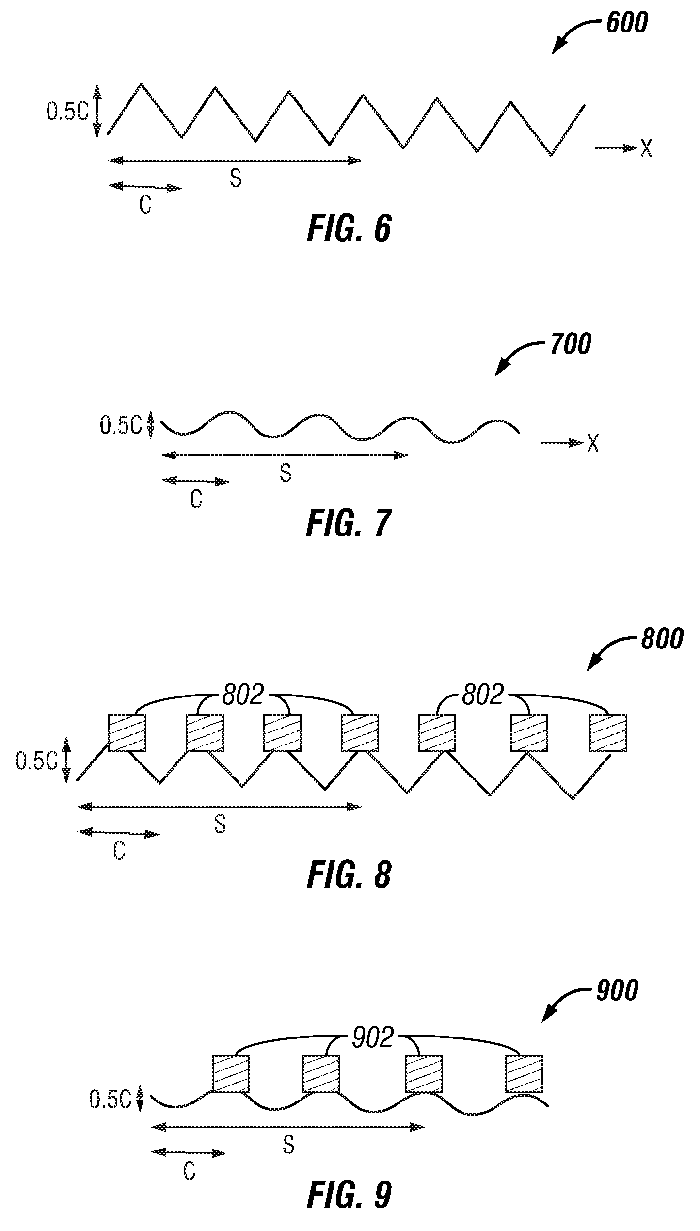
In alternative implementations, an optical fiber can be designed with curved portions, such as an optical fiber 600 or optical fiber 700 shown in FIG. 6 or 7, respectively. As depicted in FIG. 6 or 7, each optical fiber 600 or 700 is generally wavy, and is associated with a curvature C. The curvature C represents half a wavelength of the generally wavy optical fiber 600 or 700. FIG. 6 or FIG. 7 also shows the wavelength S of seismic signals, according to some examples. The amplitude range of the wavy optical fiber 600 or 700 is approximately 0.5 C, in some implementations. Different amplitude ranges can be used in other implementations. An amplitude range of the wavy optical fiber 600 or 700 refers to a range defined between a maximum peak and a minimum peak of the wavy optical fiber.
The curved portions of the optical fiber 600 or 700 allow for detection of noise components in two orthogonal directions (a first direction that is generally parallel to the dominant axial direction x of the optical fiber 600 or 700, and a second direction that is generally perpendicular to the dominant axial direction in the horizontal plane). In a first configuration, the spatial resolution R and curvature C can be designed such that R<C<N.ltoreq.S. In this case both the spatial resolution R and curvature C are less than the noise wavelength N and seismic signal wavelength S. In this manner, the distributed optical sensor 600 or 700 measures both noise and seismic signal components. Signal processing can be performed to resolve the noise and seismic signal components into two directions: the first direction and the second direction noted above. Filtering can then be applied to the noise components to perform noise attenuation.
In a second configuration, the spatial resolution R and curvature C are designed such that N.ltoreq.C.ltoreq.R<S. In this configuration, the curvature C and spatial resolution R are greater than or equal to the noise wavelength N. The distributed sensor in this arrangement will average the noise component in the different horizontal directions to provide a two-dimensional spatial filter for noise mitigation (in which noise is attenuated).
In each of the FIG. 6 or FIG. 7 implementations, the optical fiber has a dominant axial direction x--however, in implementations in which the optical fiber is laid out in a generally curved two-dimensional pattern, where the optical fiber weaves back and forth in many different directions (such as in the x-y plane), there may not be any dominant axial direction. In these cases, the generally wavy shape of the optical fiber allows the detection of noise and/or seismic signal components in two different directions.
An optical fiber with curved portions can also be employed in implementations that use seismic sensors, such as in the FIG. 3 arrangement. FIG. 8 shows a wavy optical fiber 800 used with seismic sensors 802, and FIG. 9 shows another wavy optical fiber 900 used with seismic sensors 904. The wavy optical fibers 800 and 900 are similar to the wavy optical fiber 600 and 700.
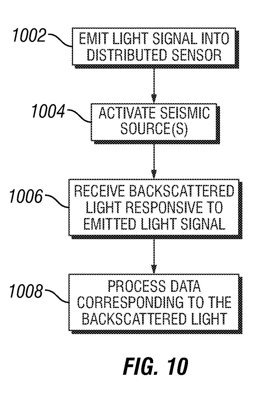
FIG. 10 depicts a process of performing seismic surveying according to some embodiments. Light signal is emitted (at 1002) by the interrogation subsystem 102 into an optical fiber of a distributed sensor. Seismic source(s) is (are) activated (at 1004), which causes seismic signals to be propagated into a subterranean structure, with a portion reflected from the subterranean structure. Backscattered light is received (at 1006) from the optical fiber, where the backscattered light is responsive to the emitted light signal. The backscattered light is affected by perturbations, which can include noise and/or seismic signals. The received backscattered light is converted into corresponding data output to the processing subsystem 110. In general, many optical pulses will be emitted and launched into the fiber, and their backscatter collected, during the time it takes for a seismic signal to be generated, to propagate into the subterranean formation and return.
The processing subsystem 110 processes (at 1008) the data corresponding to the backscattered light to determine a characteristic of a subterranean structure. The data corresponding to the backscattered light can contain information to allow for determination of noise, or alternatively, the data can include seismic signals with the noise attenuated. As yet another alternative, the data corresponding to the backscattered light can include both noise and seismic signal components; in this latter alternative, the processing performed at 1008 would apply filtering to perform noise mitigation.
The processing subsystem 110 of FIG. 1 can include a processor (or multiple processors) to perform processing of seismic data and/or data representing backscattered light from a distributed optical sensor. Machine-readable instructions are executable on the processor(s) to perform the processing and analysis. A processor can include a microprocessor, microcontroller, processor module or subsystem, programmable integrated circuit, programmable gate array, or another control or computing device.
Data and instructions are stored in respective storage devices, which are implemented as one or more computer-readable or machine-readable storage media. The storage media include different forms of memory including semiconductor memory devices such as dynamic or static random access memories (DRAMs or SRAMs), erasable and programmable read-only memories (EPROMs), electrically erasable and programmable read-only memories (EEPROMs) and flash memories; magnetic disks such as fixed, floppy and removable disks; other magnetic media including tape; optical media such as compact disks (CDs) or digital video disks (DVDs); or other types of storage devices. Note that the instructions discussed above can be provided on one computer-readable or machine-readable storage medium, or alternatively, can be provided on multiple computer-readable or machine-readable storage media distributed in a large system having possibly plural nodes. Such computer-readable or machine-readable storage medium or media is (are) considered to be part of an article (or article of manufacture). An article or article of manufacture can refer to any manufactured single component or multiple components.
In the foregoing description, numerous details are set forth to provide an understanding of the subject disclosed herein. However, implementations may be practiced without some or all of these details. Other implementations may include modifications and variations from the details discussed above. It is intended that the appended claims cover such modifications and variations.
* * * * *
D00000
D00001
D00002
D00003
D00004
XML
uspto.report is an independent third-party trademark research tool that is not affiliated, endorsed, or sponsored by the United States Patent and Trademark Office (USPTO) or any other governmental organization. The information provided by uspto.report is based on publicly available data at the time of writing and is intended for informational purposes only.
While we strive to provide accurate and up-to-date information, we do not guarantee the accuracy, completeness, reliability, or suitability of the information displayed on this site. The use of this site is at your own risk. Any reliance you place on such information is therefore strictly at your own risk.
All official trademark data, including owner information, should be verified by visiting the official USPTO website at www.uspto.gov. This site is not intended to replace professional legal advice and should not be used as a substitute for consulting with a legal professional who is knowledgeable about trademark law.