Proximity switch based door latch release
Salter , et al. December 30, 2
U.S. patent number 8,922,340 [Application Number 13/609,390] was granted by the patent office on 2014-12-30 for proximity switch based door latch release. This patent grant is currently assigned to Ford Global Technologies, LLC. The grantee listed for this patent is Pietro Buttolo, Cornel Lewis Gardner, Yun Shin Lee, Stuart C. Salter. Invention is credited to Pietro Buttolo, Cornel Lewis Gardner, Yun Shin Lee, Stuart C. Salter.

| United States Patent | 8,922,340 |
| Salter , et al. | December 30, 2014 |
Proximity switch based door latch release
Abstract
A vehicle door latch assembly includes a first proximity sensor on a first side of a door handle and a second proximity sensor on a second side of the door handle. The assembly also includes a latch operative to latch the door closed and to unlatch the door to allow the door to open. The assembly further includes control circuitry for activating the latch to unlatch the door based on an object such as an operator's hand sensed with both the first and second proximity sensors.
| Inventors: | Salter; Stuart C. (White Lake, MI), Lee; Yun Shin (Shelby Township, MI), Buttolo; Pietro (Dearborn Heights, MI), Gardner; Cornel Lewis (Romulus, MI) | ||||||||||
|---|---|---|---|---|---|---|---|---|---|---|---|
| Applicant: |
|
||||||||||
| Assignee: | Ford Global Technologies, LLC
(Dearborn, MI) |
||||||||||
| Family ID: | 50153535 | ||||||||||
| Appl. No.: | 13/609,390 | ||||||||||
| Filed: | September 11, 2012 |
Prior Publication Data
| Document Identifier | Publication Date | |
|---|---|---|
| US 20140069015 A1 | Mar 13, 2014 | |
| Current U.S. Class: | 340/5.72; 340/426.28; 340/5.7; 340/5.2 |
| Current CPC Class: | E05B 81/00 (20130101); E05B 81/77 (20130101); E05C 19/02 (20130101); E05B 85/12 (20130101); G07C 9/00714 (20130101); E05B 81/76 (20130101) |
| Current International Class: | B60R 25/00 (20130101) |
| Field of Search: | ;340/5.72,5.7,5.2,426.28 |
References Cited [Referenced By]
U.S. Patent Documents
| 3382588 | May 1968 | Serrell et al. |
| 3544804 | December 1970 | Gaumer et al. |
| 3691396 | September 1972 | Hinrichs |
| 3707671 | December 1972 | Morrow et al. |
| 3826979 | July 1974 | Steinmann |
| 4204204 | May 1980 | Pitstick |
| 4205325 | May 1980 | Haygood et al. |
| 4232289 | November 1980 | Daniel |
| 4257117 | March 1981 | Besson |
| 4290052 | September 1981 | Eichelberger et al. |
| 4340813 | July 1982 | Sauer |
| 4374381 | February 1983 | Ng et al. |
| 4380040 | April 1983 | Posset |
| 4413252 | November 1983 | Tyler et al. |
| 4431882 | February 1984 | Frame |
| 4446380 | May 1984 | Moriya et al. |
| 4453112 | June 1984 | Sauer et al. |
| 4492958 | January 1985 | Minami |
| 4494105 | January 1985 | House |
| 4502726 | March 1985 | Adams |
| 4514817 | April 1985 | Pepper et al. |
| 4613802 | September 1986 | Kraus et al. |
| 4680429 | July 1987 | Murdock et al. |
| 4743895 | May 1988 | Alexander |
| 4748390 | May 1988 | Okushima et al. |
| 4758735 | July 1988 | Ingraham |
| 4821029 | April 1989 | Logan et al. |
| 4855550 | August 1989 | Schultz, Jr. |
| 4872485 | October 1989 | Laverty, Jr. |
| 4899138 | February 1990 | Araki et al. |
| 4901074 | February 1990 | Sinn et al. |
| 4905001 | February 1990 | Penner |
| 4924222 | May 1990 | Antikidis et al. |
| 4972070 | November 1990 | Laverty, Jr. |
| 5025516 | June 1991 | Wilson |
| 5033508 | July 1991 | Laverty, Jr. |
| 5036321 | July 1991 | Leach et al. |
| 5063306 | November 1991 | Edwards |
| 5108530 | April 1992 | Niebling, Jr. et al. |
| 5153590 | October 1992 | Charlier |
| 5159159 | October 1992 | Asher |
| 5159276 | October 1992 | Reddy, III |
| 5177341 | January 1993 | Balderson |
| 5215811 | June 1993 | Reafler et al. |
| 5239152 | August 1993 | Caldwell et al. |
| 5270710 | December 1993 | Gaultier et al. |
| 5294889 | March 1994 | Heep et al. |
| 5329239 | July 1994 | Kindermann et al. |
| 5341231 | August 1994 | Yamamoto et al. |
| 5403980 | April 1995 | Eckrich |
| 5451724 | September 1995 | Nakazawa et al. |
| 5467080 | November 1995 | Stoll et al. |
| 5477422 | December 1995 | Hooker et al. |
| 5494180 | February 1996 | Callahan |
| 5512836 | April 1996 | Chen et al. |
| 5548268 | August 1996 | Collins |
| 5566702 | October 1996 | Philipp |
| 5572205 | November 1996 | Caldwell et al. |
| 5586042 | December 1996 | Pisau et al. |
| 5594222 | January 1997 | Caldwell |
| 5598527 | January 1997 | Debrus et al. |
| 5670886 | September 1997 | Wolff et al. |
| 5681515 | October 1997 | Pratt et al. |
| 5730165 | March 1998 | Philipp |
| 5747756 | May 1998 | Boedecker |
| 5760554 | June 1998 | Bustamante |
| 5790107 | August 1998 | Kasser et al. |
| 5796183 | August 1998 | Hourmand |
| 5825352 | October 1998 | Bisset et al. |
| 5827980 | October 1998 | Doemens et al. |
| 5864105 | January 1999 | Andrews |
| 5867111 | February 1999 | Caldwell et al. |
| 5874672 | February 1999 | Gerardi et al. |
| 5917165 | June 1999 | Platt et al. |
| 5920309 | July 1999 | Bisset et al. |
| 5942733 | August 1999 | Allen et al. |
| 5963000 | October 1999 | Tsutsumi et al. |
| 5973417 | October 1999 | Goetz et al. |
| 5973623 | October 1999 | Gupta et al. |
| 6010742 | January 2000 | Tanabe et al. |
| 6011602 | January 2000 | Miyashita et al. |
| 6031465 | February 2000 | Burgess |
| 6035180 | March 2000 | Kubes et al. |
| 6037930 | March 2000 | Wolfe et al. |
| 6040534 | March 2000 | Beukema |
| 6157372 | December 2000 | Blackburn et al. |
| 6172666 | January 2001 | Okura |
| 6215476 | April 2001 | Depew et al. |
| 6219253 | April 2001 | Green |
| 6231111 | May 2001 | Carter et al. |
| 6275644 | August 2001 | Domas et al. |
| 6288707 | September 2001 | Philipp |
| 6292100 | September 2001 | Dowling |
| 6310611 | October 2001 | Caldwell |
| 6320282 | November 2001 | Caldwell |
| 6323919 | November 2001 | Yang et al. |
| 6369369 | April 2002 | Kochman et al. |
| 6377009 | April 2002 | Philipp |
| 6379017 | April 2002 | Nakabayashi et al. |
| 6380931 | April 2002 | Gillespie et al. |
| 6415138 | July 2002 | Sirola et al. |
| 6427540 | August 2002 | Monroe et al. |
| 6452138 | September 2002 | Kochman et al. |
| 6452514 | September 2002 | Philipp |
| 6456027 | September 2002 | Pruessel |
| 6457355 | October 2002 | Philipp |
| 6464381 | October 2002 | Anderson, Jr. et al. |
| 6466036 | October 2002 | Philipp |
| 6485595 | November 2002 | Yenni, Jr. et al. |
| 6529125 | March 2003 | Butler et al. |
| 6535200 | March 2003 | Philipp |
| 6537359 | March 2003 | Spa |
| 6559902 | May 2003 | Kusuda et al. |
| 6587097 | July 2003 | Aufderheide et al. |
| 6607413 | August 2003 | Stevenson et al. |
| 6614579 | September 2003 | Roberts et al. |
| 6617975 | September 2003 | Burgess |
| 6639159 | October 2003 | Anzai |
| 6652777 | November 2003 | Rapp et al. |
| 6654006 | November 2003 | Kawashima et al. |
| 6661410 | December 2003 | Casebolt et al. |
| 6664489 | December 2003 | Kleinhans et al. |
| 6713897 | March 2004 | Caldwell |
| 6734377 | May 2004 | Gremm et al. |
| 6738051 | May 2004 | Boyd et al. |
| 6740416 | May 2004 | Yokogawa et al. |
| 6756970 | June 2004 | Keely, Jr. et al. |
| 6773129 | August 2004 | Anderson, Jr. et al. |
| 6774505 | August 2004 | Wnuk |
| 6794728 | September 2004 | Kithil |
| 6795226 | September 2004 | Agrawal et al. |
| 6809280 | October 2004 | Divigalpitiya et al. |
| 6812424 | November 2004 | Miyako |
| 6819316 | November 2004 | Schulz et al. |
| 6819990 | November 2004 | Ichinose |
| 6825752 | November 2004 | Nahata et al. |
| 6834373 | December 2004 | Dieberger |
| 6841748 | January 2005 | Serizawa et al. |
| 6847018 | January 2005 | Wong |
| 6847289 | January 2005 | Pang et al. |
| 6854870 | February 2005 | Huizenga |
| 6879250 | April 2005 | Fayt et al. |
| 6884936 | April 2005 | Takahashi et al. |
| 6891114 | May 2005 | Peterson |
| 6891530 | May 2005 | Umemoto et al. |
| 6897390 | May 2005 | Caldwell et al. |
| 6929900 | August 2005 | Farquhar et al. |
| 6930672 | August 2005 | Kuribayashi |
| 6940291 | September 2005 | Ozick |
| 6960735 | November 2005 | Hein et al. |
| 6962436 | November 2005 | Holloway et al. |
| 6964023 | November 2005 | Maes et al. |
| 6966225 | November 2005 | Mallary |
| 6967587 | November 2005 | Snell et al. |
| 6977615 | December 2005 | Brandwein, Jr. |
| 6987605 | January 2006 | Liang et al. |
| 6993607 | January 2006 | Philipp |
| 6999066 | February 2006 | Litwiller |
| 7030513 | April 2006 | Caldwell |
| 7046129 | May 2006 | Regnet et al. |
| 7053360 | May 2006 | Balp et al. |
| 7063379 | June 2006 | Steuer et al. |
| 7091836 | August 2006 | Kachouh et al. |
| 7091886 | August 2006 | DePue et al. |
| 7098414 | August 2006 | Caldwell |
| 7105752 | September 2006 | Tsai et al. |
| 7106171 | September 2006 | Burgess |
| 7135995 | November 2006 | Engelmann et al. |
| 7146024 | December 2006 | Benkley, III |
| 7151450 | December 2006 | Beggs et al. |
| 7151532 | December 2006 | Schulz |
| 7154481 | December 2006 | Cross et al. |
| 7180017 | February 2007 | Hein |
| 7186936 | March 2007 | Marcus et al. |
| 7205777 | April 2007 | Schulz et al. |
| 7215529 | May 2007 | Rosenau |
| 7218498 | May 2007 | Caldwell |
| 7232973 | June 2007 | Kaps et al. |
| 7242393 | July 2007 | Caldwell |
| 7245131 | July 2007 | Kurachi et al. |
| 7248151 | July 2007 | Mc Call |
| 7248955 | July 2007 | Hein et al. |
| 7254775 | August 2007 | Geaghan et al. |
| 7255466 | August 2007 | Schmidt et al. |
| 7255622 | August 2007 | Stevenson et al. |
| 7269484 | September 2007 | Hein |
| 7295168 | November 2007 | Saegusa et al. |
| 7295904 | November 2007 | Kanevsky et al. |
| 7339579 | March 2008 | Richter et al. |
| 7342485 | March 2008 | Joehl et al. |
| 7355595 | April 2008 | Bathiche et al. |
| 7361860 | April 2008 | Caldwell |
| 7385308 | June 2008 | Yerdon et al. |
| 7445350 | November 2008 | Konet et al. |
| 7479788 | January 2009 | Bolender et al. |
| 7489053 | February 2009 | Gentile et al. |
| 7521941 | April 2009 | Ely et al. |
| 7521942 | April 2009 | Reynolds |
| 7531921 | May 2009 | Cencur |
| 7532202 | May 2009 | Roberts |
| 7535131 | May 2009 | Safieh, Jr. |
| 7535459 | May 2009 | You et al. |
| 7567240 | July 2009 | Peterson, Jr. et al. |
| 7583092 | September 2009 | Reynolds et al. |
| 7643010 | January 2010 | Westerman et al. |
| 7653883 | January 2010 | Hotelling et al. |
| 7688080 | March 2010 | Golovchenko et al. |
| 7701440 | April 2010 | Harley |
| 7705257 | April 2010 | Arione et al. |
| 7708120 | May 2010 | Einbinder |
| 7710245 | May 2010 | Pickering |
| 7714846 | May 2010 | Gray |
| 7719142 | May 2010 | Hein et al. |
| 7728819 | June 2010 | Inokawa |
| 7737953 | June 2010 | Mackey |
| 7737956 | June 2010 | Hsieh et al. |
| 7777732 | August 2010 | Herz et al. |
| 7782307 | August 2010 | Westerman et al. |
| 7791594 | September 2010 | Dunko |
| 7795882 | September 2010 | Kirchner et al. |
| 7800590 | September 2010 | Satoh et al. |
| 7821425 | October 2010 | Philipp |
| 7834853 | November 2010 | Finney et al. |
| 7839392 | November 2010 | Pak et al. |
| 7876310 | January 2011 | Westerman et al. |
| 7881940 | February 2011 | Dusterhoff |
| RE42199 | March 2011 | Caldwell |
| 7898531 | March 2011 | Bowden et al. |
| 7920131 | April 2011 | Westerman |
| 7924143 | April 2011 | Griffin et al. |
| 7957864 | June 2011 | Lenneman et al. |
| 7977596 | July 2011 | Born et al. |
| 7978181 | July 2011 | Westerman |
| 7989752 | August 2011 | Yokozawa |
| 8026904 | September 2011 | Westerman |
| 8050876 | November 2011 | Feen et al. |
| 8054296 | November 2011 | Land et al. |
| 8054300 | November 2011 | Bernstein |
| 8077154 | December 2011 | Emig et al. |
| 8090497 | January 2012 | Ando |
| 8253425 | August 2012 | Reynolds et al. |
| 8283800 | October 2012 | Salter et al. |
| 8330385 | December 2012 | Salter et al. |
| 8339286 | December 2012 | Cordeiro |
| 8454181 | June 2013 | Salter et al. |
| 8508487 | August 2013 | Schwesig et al. |
| 8517383 | August 2013 | Wallace et al. |
| 8537107 | September 2013 | Li |
| 8575949 | November 2013 | Salter et al. |
| 2001/0019228 | September 2001 | Gremm |
| 2001/0028558 | October 2001 | Rapp et al. |
| 2002/0040266 | April 2002 | Edgar et al. |
| 2002/0084721 | July 2002 | Walczak |
| 2002/0093786 | July 2002 | Maser |
| 2002/0149376 | October 2002 | Haffner et al. |
| 2002/0167439 | November 2002 | Bloch et al. |
| 2002/0167704 | November 2002 | Kleinhans et al. |
| 2003/0002273 | January 2003 | Anderson, Jr. et al. |
| 2003/0101781 | June 2003 | Budzynski et al. |
| 2003/0122554 | July 2003 | Karray et al. |
| 2003/0128116 | July 2003 | Ieda et al. |
| 2004/0056753 | March 2004 | Chiang et al. |
| 2004/0145613 | July 2004 | Stavely et al. |
| 2004/0160072 | August 2004 | Carter et al. |
| 2004/0160234 | August 2004 | Denen et al. |
| 2004/0160713 | August 2004 | Wei |
| 2004/0197547 | October 2004 | Bristow et al. |
| 2004/0246239 | December 2004 | Knowles et al. |
| 2005/0052429 | March 2005 | Philipp |
| 2005/0068712 | March 2005 | Schulz et al. |
| 2005/0088417 | April 2005 | Mulligan |
| 2005/0110769 | May 2005 | DaCosta et al. |
| 2005/0137765 | June 2005 | Hein et al. |
| 2005/0242923 | November 2005 | Pearson et al. |
| 2005/0275567 | December 2005 | DePue et al. |
| 2006/0022682 | February 2006 | Nakamura et al. |
| 2006/0038793 | February 2006 | Philipp |
| 2006/0044800 | March 2006 | Reime |
| 2006/0082545 | April 2006 | Choquet et al. |
| 2006/0170241 | August 2006 | Yamashita |
| 2006/0244733 | November 2006 | Geaghan |
| 2006/0262549 | November 2006 | Schmidt et al. |
| 2006/0267953 | November 2006 | Peterson, Jr. et al. |
| 2006/0279015 | December 2006 | Wang |
| 2006/0287474 | December 2006 | Crawford et al. |
| 2007/0008726 | January 2007 | Brown |
| 2007/0023265 | February 2007 | Ishikawa et al. |
| 2007/0051609 | March 2007 | Parkinson |
| 2007/0068790 | March 2007 | Yerdon et al. |
| 2007/0096565 | May 2007 | Breed et al. |
| 2007/0103431 | May 2007 | Tabatowski-Bush |
| 2007/0226994 | October 2007 | Wollach et al. |
| 2007/0232779 | October 2007 | Moody et al. |
| 2007/0247429 | October 2007 | Westerman |
| 2007/0255468 | November 2007 | Strebel et al. |
| 2007/0257891 | November 2007 | Esenther et al. |
| 2007/0296709 | December 2007 | GuangHai |
| 2008/0012835 | January 2008 | Rimon et al. |
| 2008/0018604 | January 2008 | Paun et al. |
| 2008/0023715 | January 2008 | Choi |
| 2008/0030465 | February 2008 | Konet et al. |
| 2008/0074398 | March 2008 | Wright |
| 2008/0111714 | May 2008 | Kremin |
| 2008/0136792 | June 2008 | Peng et al. |
| 2008/0142352 | June 2008 | Wright |
| 2008/0143681 | June 2008 | XiaoPing |
| 2008/0150905 | June 2008 | Grivna et al. |
| 2008/0158146 | July 2008 | Westerman |
| 2008/0196945 | August 2008 | Konstas |
| 2008/0202912 | August 2008 | Boddie et al. |
| 2008/0231290 | September 2008 | Zhitomirsky |
| 2008/0238650 | October 2008 | Riihimaki et al. |
| 2008/0257706 | October 2008 | Haag |
| 2008/0272623 | November 2008 | Kadzban et al. |
| 2009/0066659 | March 2009 | He et al. |
| 2009/0079699 | March 2009 | Sun |
| 2009/0108985 | April 2009 | Haag et al. |
| 2009/0115731 | May 2009 | Rak |
| 2009/0120697 | May 2009 | Wilner et al. |
| 2009/0135157 | May 2009 | Harley |
| 2009/0225043 | September 2009 | Rosener |
| 2009/0235588 | September 2009 | Patterson et al. |
| 2009/0236210 | September 2009 | Clark et al. |
| 2009/0251435 | October 2009 | Westerman et al. |
| 2009/0256677 | October 2009 | Hein et al. |
| 2009/0309616 | December 2009 | Klinghult et al. |
| 2010/0001974 | January 2010 | Su et al. |
| 2010/0007613 | January 2010 | Costa |
| 2010/0007620 | January 2010 | Hsieh et al. |
| 2010/0013777 | January 2010 | Baudisch et al. |
| 2010/0026654 | February 2010 | Suddreth |
| 2010/0039392 | February 2010 | Pratt et al. |
| 2010/0090712 | April 2010 | Vandermeijden |
| 2010/0090966 | April 2010 | Gregorio |
| 2010/0102830 | April 2010 | Curtis et al. |
| 2010/0103139 | April 2010 | Soo et al. |
| 2010/0110037 | May 2010 | Huang et al. |
| 2010/0125393 | May 2010 | Jarvinen et al. |
| 2010/0156814 | June 2010 | Weber et al. |
| 2010/0177057 | July 2010 | Flint et al. |
| 2010/0188356 | July 2010 | Vu et al. |
| 2010/0188364 | July 2010 | Lin et al. |
| 2010/0194692 | August 2010 | Orr et al. |
| 2010/0207907 | August 2010 | Tanabe et al. |
| 2010/0212819 | August 2010 | Salter et al. |
| 2010/0214253 | August 2010 | Wu et al. |
| 2010/0219935 | September 2010 | Bingle et al. |
| 2010/0241431 | September 2010 | Weng et al. |
| 2010/0241983 | September 2010 | Walline et al. |
| 2010/0245286 | September 2010 | Parker |
| 2010/0250071 | September 2010 | Pala et al. |
| 2010/0277431 | November 2010 | Klinghult |
| 2010/0280983 | November 2010 | Cho et al. |
| 2010/0286867 | November 2010 | Bergholz et al. |
| 2010/0289754 | November 2010 | Sleeman et al. |
| 2010/0289759 | November 2010 | Fisher et al. |
| 2010/0296303 | November 2010 | Sarioglu et al. |
| 2010/0302200 | December 2010 | Netherton et al. |
| 2010/0315267 | December 2010 | Chung et al. |
| 2010/0321214 | December 2010 | Wang et al. |
| 2010/0321321 | December 2010 | Shenfield et al. |
| 2010/0321335 | December 2010 | Lim et al. |
| 2010/0328261 | December 2010 | Woolley et al. |
| 2010/0328262 | December 2010 | Huang et al. |
| 2011/0001707 | January 2011 | Faubert et al. |
| 2011/0001722 | January 2011 | Newman et al. |
| 2011/0007021 | January 2011 | Bernstein et al. |
| 2011/0007023 | January 2011 | Abrahamsson et al. |
| 2011/0012623 | January 2011 | Gastel et al. |
| 2011/0018744 | January 2011 | Philipp |
| 2011/0018817 | January 2011 | Kryze et al. |
| 2011/0022393 | January 2011 | Waller et al. |
| 2011/0031983 | February 2011 | David et al. |
| 2011/0034219 | February 2011 | Filson et al. |
| 2011/0037725 | February 2011 | Pryor |
| 2011/0037735 | February 2011 | Land et al. |
| 2011/0039602 | February 2011 | McNamara et al. |
| 2011/0041409 | February 2011 | Newman et al. |
| 2011/0043481 | February 2011 | Bruwer |
| 2011/0050251 | March 2011 | Franke et al. |
| 2011/0050587 | March 2011 | Natanzon et al. |
| 2011/0050618 | March 2011 | Murphy et al. |
| 2011/0050620 | March 2011 | Hristov |
| 2011/0055753 | March 2011 | Horodezky et al. |
| 2011/0062969 | March 2011 | Hargreaves et al. |
| 2011/0063425 | March 2011 | Tieman |
| 2011/0074573 | March 2011 | Seshadri |
| 2011/0080365 | April 2011 | Westerman |
| 2011/0080366 | April 2011 | Bolender |
| 2011/0080376 | April 2011 | Kuo et al. |
| 2011/0082616 | April 2011 | Small et al. |
| 2011/0083110 | April 2011 | Griffin et al. |
| 2011/0095997 | April 2011 | Philipp |
| 2011/0115732 | May 2011 | Coni et al. |
| 2011/0115742 | May 2011 | Sobel et al. |
| 2011/0134047 | June 2011 | Wigdor et al. |
| 2011/0134054 | June 2011 | Woo et al. |
| 2011/0141006 | June 2011 | Rabu |
| 2011/0141041 | June 2011 | Parkinson et al. |
| 2011/0148803 | June 2011 | Xu |
| 2011/0157037 | June 2011 | Shamir et al. |
| 2011/0157079 | June 2011 | Wu et al. |
| 2011/0157080 | June 2011 | Ciesla et al. |
| 2011/0157089 | June 2011 | Rainisto |
| 2011/0161001 | June 2011 | Fink |
| 2011/0169758 | July 2011 | Aono |
| 2011/0187492 | August 2011 | Newman et al. |
| 2011/0279276 | November 2011 | Newham |
| 2011/0279409 | November 2011 | Salaverry et al. |
| 2011/0309912 | December 2011 | Muller |
| 2012/0007821 | January 2012 | Zaliva |
| 2012/0037485 | February 2012 | Sitarski |
| 2012/0043976 | February 2012 | Bokma et al. |
| 2012/0055557 | March 2012 | Belz et al. |
| 2012/0062247 | March 2012 | Chang |
| 2012/0062498 | March 2012 | Weaver et al. |
| 2012/0068956 | March 2012 | Jira et al. |
| 2012/0154324 | June 2012 | Wright et al. |
| 2012/0217147 | August 2012 | Porter et al. |
| 2012/0312676 | December 2012 | Salter et al. |
| 2012/0313648 | December 2012 | Salter et al. |
| 2013/0024169 | January 2013 | Veerasamy |
| 2013/0036529 | February 2013 | Salter et al. |
| 2013/0076121 | March 2013 | Salter et al. |
| 2013/0093500 | April 2013 | Bruwer |
| 2013/0106436 | May 2013 | Brunet et al. |
| 2013/0113397 | May 2013 | Salter et al. |
| 2013/0113544 | May 2013 | Salter et al. |
| 2013/0126325 | May 2013 | Curtis et al. |
| 2013/0270896 | October 2013 | Buttolo et al. |
| 2013/0270899 | October 2013 | Buttolo et al. |
| 2013/0271157 | October 2013 | Buttolo et al. |
| 2013/0271159 | October 2013 | Santos et al. |
| 2013/0271182 | October 2013 | Buttolo et al. |
| 2013/0271202 | October 2013 | Buttolo et al. |
| 2013/0271203 | October 2013 | Salter et al. |
| 2013/0271204 | October 2013 | Salter et al. |
| 2013/0291439 | November 2013 | Wuerstlein et al. |
| 2013/0307610 | November 2013 | Salter et al. |
| 2013/0321065 | December 2013 | Salter et al. |
| 2013/0328616 | December 2013 | Buttolo et al. |
| 2014/0002405 | January 2014 | Salter et al. |
| 2014/0145733 | May 2014 | Buttolo et al. |
| 4024052 | Jan 1992 | DE | |||
| 1152443 | Nov 2001 | EP | |||
| 1327860 | Jul 2003 | EP | |||
| 1562293 | Aug 2005 | EP | |||
| 2133777 | Oct 2011 | EP | |||
| 2133777 | Oct 2011 | EP | |||
| 2071338 | Sep 1981 | GB | |||
| 2158737 | Nov 1985 | GB | |||
| 2279750 | Jan 1995 | GB | |||
| 2409578 | Jun 2005 | GB | |||
| 2418741 | Apr 2006 | GB | |||
| 61188515 | Aug 1986 | JP | |||
| 4065038 | Mar 1992 | JP | |||
| 04082416 | Mar 1992 | JP | |||
| 07315880 | Dec 1995 | JP | |||
| 08138446 | May 1996 | JP | |||
| 11065764 | Mar 1999 | JP | |||
| 11110131 | Apr 1999 | JP | |||
| 11260133 | Sep 1999 | JP | |||
| 11316553 | Nov 1999 | JP | |||
| 2000047178 | Feb 2000 | JP | |||
| 2000075293 | Mar 2000 | JP | |||
| 2001013868 | Jan 2001 | JP | |||
| 2006007764 | Jan 2006 | JP | |||
| 2007027034 | Feb 2007 | JP | |||
| 2008033701 | Feb 2008 | JP | |||
| 2010139362 | Jun 2010 | JP | |||
| 2010165618 | Jul 2010 | JP | |||
| 2010218422 | Sep 2010 | JP | |||
| 2010239587 | Oct 2010 | JP | |||
| 2010287148 | Dec 2010 | JP | |||
| 2011014280 | Jan 2011 | JP | |||
| 20040110463 | Dec 2004 | KR | |||
| 20090127544 | Dec 2009 | KR | |||
| 20100114768 | Oct 2010 | KR | |||
| 9636960 | Nov 1996 | WO | |||
| 9963394 | Dec 1999 | WO | |||
| 2006093398 | Sep 2006 | WO | |||
| 2007022027 | Feb 2007 | WO | |||
| 2008121760 | Oct 2008 | WO | |||
| 2009054592 | Apr 2009 | WO | |||
| 2010111362 | Sep 2010 | WO | |||
| 2012032318 | Mar 2012 | WO | |||
| 2012032318 | Mar 2012 | WO | |||
| 2012169106 | Dec 2012 | WO | |||
| 2012169106 | Dec 2012 | WO | |||
Other References
|
US. Appl. No. 13/665,253, filed Oct. 31, 2012, entitled Proximity Switch Assembly Having Round Layer, (15 pages of specification and 7 pages of drawings) and Official Filing Receipt (3 pages). cited by applicant . U.S. Appl. No. 13/799,413, filed Mar. 13, 2013, entitled "Proximity Interface Development System Having Replicator and Method," (29 pages of specification and 20 pages of drawings) and Official Filing Receipt (3 pages). cited by applicant . U.S. Appl. No. 13/799,478, filed Mar. 13, 2013, entitled "Proximity Interface Development System Having Analyzer and Method," (29 pages of specification and 20 pages of drawings) and Official Filing Receipt (3 pages). cited by applicant . U.S. Appl. No. 14/168,614, filed Jan. 30, 2014, entitled "Proximity Switch Assembly and Activation Method Having Virtual Button Mode," (30 pages of specification and 15 pages of drawings) and Official Filing Receipt (3 pages). cited by applicant . "Touch Sensors Design Guide" by ATMEL, 10620 D-AT42-04/09, Revised Apr. 2009, 72 pages, Copyrighted 2008-2009 Atmel Corporation. cited by applicant . "Capacitive Tough Switches for Automotive Applications," by Dave Van Ess of Cypress Semiconductor Corp., Published in Automotive DesignLine (http://www.automotivedesignline.com), Feb. 2006, 7 pages. cited by applicant . "Clevios P Formulation Guide," 12 pages, www.clevios.com, Heraeus Clevios GmbH, no date provided. cited by applicant . "Introduction to Touch Solutions, White Paper, Rivision 1.0 A," Densitron Corporation, 14 pages, Aug. 21, 2007. cited by applicant . Kliffken, Marksu G. et al., "Obstacle Detection for Power Operated Window-Lift and Sunroof Actuation Systems," Paper No. 2001-01-0466, 1 page, .COPYRGT.2011 SAE International, Published Mar. 5, 2001. cited by applicant . NXP Capacitive Sensors, 1 page, www.nxp.com, copyrighted 2006-2010, NXP Semiconductors. cited by applicant . "Moisture Immunity in QuickSense Studio," AN552, Rev. 0.1 10/10, 8 pages, Silicon Laboratories, Inc., .COPYRGT. 2010. cited by applicant . "Orgacon EL-P3000, Screen printing Ink Series 3000," 2 pages, AGFA, last updated in Feb. 2006. cited by applicant . "Charge-Transfer Sensing-Based Touch Controls Facilitate Creative Interfaces," www.ferret.com.au, 2 pages, Jan. 18, 2006. cited by applicant . Kiosk Peripherals, "Touch Screen," www.bitsbytesintegrators.com/kiosk-peripherals.html, 10 pages, no date provided. cited by applicant . JVC KD-AVX777 Detachable Front-Panel with Integrated 5.4'' Touch-Screen Monitor, 6 pages, www.crutchfield.com, no date provided. cited by applicant . Ergonomic Palm Buttons, Pepperl+Fuchs, www.wolfautomation.com, 6 pages, no date provided. cited by applicant . U.S. Appl. No. 14/314,328, filed Jun. 25, 2014, entitled "Proximity Switch Assembly Having Pliable Surface and Depression," (43 pages of specification and 24 pages of drawings) and Official Filing Receipt (3 pages). cited by applicant . U.S. Appl. No. 14/314,364, filed Jun. 25, 2014, entitled "Proximity Switch Assembly Having Groove Between Adjacent Proximity Sensors," (43 pages of specification and 24 pages of drawings) and Official Filing Receipt (3 pages). cited by applicant. |
Primary Examiner: Bee; Andrew
Attorney, Agent or Firm: Chea; Vichit Price Heneveld LLP
Claims
We claim:
1. A door latch assembly comprising: a first proximity sensor on a first side of a door handle; a second proximity sensor on a second side of the door handle; a latch operative to latch the door closed and to unlatch the door to allow the door to open; and control circuitry for activating the latch to unlatch the door based on an object sensed with both the first and second proximity sensors, wherein the control circuitry further detects movement of the object in a direction on one of the first and second proximity sensors and determines a swipe motion indicative of one of a door lock and unlock command, wherein the control circuitry causes the door latch to lock or unlock based on the command.
2. The door latch assembly of claim 1, wherein the control circuitry detects the object with both the first and second proximity sensors at the same time and generates an output signal to activate the latch to an unlatched position.
3. The door latch assembly of claim 1, wherein the first side is substantially opposite the second side.
4. The door latch assembly of claim 1, wherein the first side is at an angle greater than ninety degrees relative to the second side.
5. The door latch assembly of claim 1, wherein the latch comprises an electromagnetic latch.
6. The door latch assembly of claim 1, wherein the first and second proximity sensors comprise capacitive sensors.
7. The door latch assembly of claim 1, wherein the assembly is employed on a vehicle.
8. The door latch assembly of claim 1, wherein at least one of the first and second proximity sensors employs a plurality of proximity sensors.
9. A door latch assembly comprising: a first proximity sensor on a first side of a door handle; a second proximity sensor on a second side of the door handle; a latch operative to latch the door closed and to unlatch the door to allow the door to open; and control circuitry or activating the latch to unlatch the door based on an object sensed with both the first and second proximity sensors, wherein the control circuitry determines a size of the object relative to one of the first and second proximity sensors based on a plurality of sensor fields and provides an output signal to the latch only when the size exceeds a predetermined size.
10. A vehicle door latch assembly comprising: a first proximity sensor located on a first side of a vehicle door handle; a second proximity sensor located on a second side of the vehicle door handle; a latch operative to latch the door closed and to unlatch the door open; and control circuitry for activating the latch to unlatch the door based on an object sensed with both the first and second proximity sensors, wherein the control circuitry determines a size of the object relative to one of the first and second proximity sensors based on a plurality of sensor fields and provides an output signal to the latch only when the size exceeds a predetermined size.
11. The vehicle door latch assembly of claim 10, wherein the control circuitry detects the object with both the first and second proximity sensors at the same time and generates an output signal to activate the latch to the unlatched position.
12. The vehicle door latch assembly of claim 10, wherein the first side is substantially opposite the second side.
13. The vehicle door latch assembly of claim 10, wherein the first side is at an angle greater than ninety degrees relative to the second side.
14. The vehicle door latch assembly of claim 10, wherein the latch comprises an electromagnetic latch.
15. The vehicle door latch assembly of claim 10, wherein the control circuitry further detects movement of the object in a direction on one of the first and second proximity sensors and determines a swipe motion indicative of one of a door lock and unlock command, wherein the control circuitry causes the door latch to lock or unlock based on the command.
16. The vehicle door latch assembly of claim 10, wherein the first and second proximity sensors comprise capacitive sensors.
17. The vehicle door latch assembly of claim 10, wherein at least one of the first and second proximity sensors employs a plurality of proximity sensors.
Description
FIELD OF THE INVENTION
The present invention generally relates to door latch release assemblies, and more particularly relates to a proximity sensor based latch assembly that releases a vehicle door latch to allow the door to open.
BACKGROUND OF THE INVENTION
Automotive vehicles include various door assemblies for allowing access to the vehicle, such as passenger doors allowing access to the passenger compartment. The vehicle doors typically include a mechanical latch assembly that latches the door in the closed position and is operable by a user to unlatch the door to allow the door to open. For example, a passenger may actuate a pivoting release mechanism by pulling on the mechanism to unlatch the vehicle door. The latch may be locked further with a door lock mechanism that typically is actuated with another input by the user.
SUMMARY OF THE INVENTION
According to one aspect of the present invention, a door latch assembly is provided. The door latch assembly includes a first proximity sensor on a first side of a door handle and a second proximity sensor on a second side of the door handle. The door latch assembly also includes a latch operative to latch the door closed and to unlatch the door to allow the door to open. The door latch assembly further includes control circuitry for activating the latch to unlatch the door based on an object sensed with both the first and second proximity sensors.
According to another aspect of the present invention, a vehicle door latch assembly is provided. The vehicle door latch assembly includes a first proximity sensor located on a first side of a vehicle door handle and a second proximity sensor located on a second side of the vehicle door handle. The vehicle door latch assembly also includes a latch operative to latch the door closed and to unlatch the door open. The vehicle door latch assembly further includes control circuitry for activating the latch to unlatch the door based on an object sensed with both the first and second proximity sensors.
These and other aspects, objects, and features of the present invention will be understood and appreciated by those skilled in the art upon studying the following specification, claims, and appended drawings.
BRIEF DESCRIPTION OF THE DRAWINGS
In the drawings:
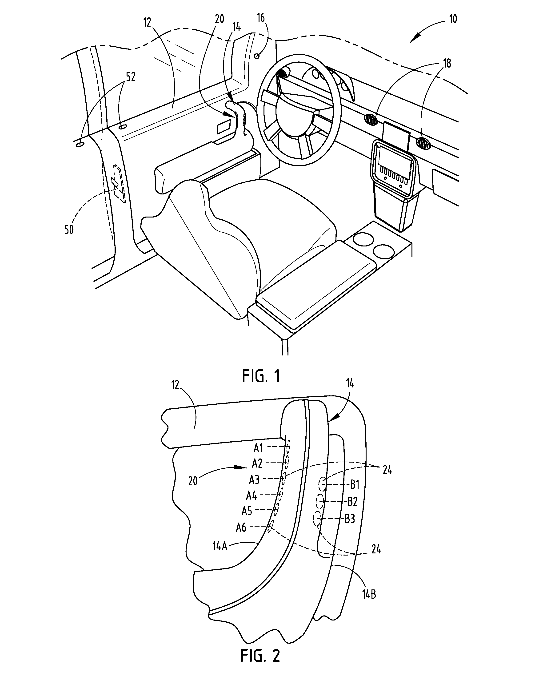
FIG. 1 is a perspective view of a passenger compartment of an automotive vehicle having a vehicle door employing a proximity sensor activated door latch assembly, according to one embodiment;
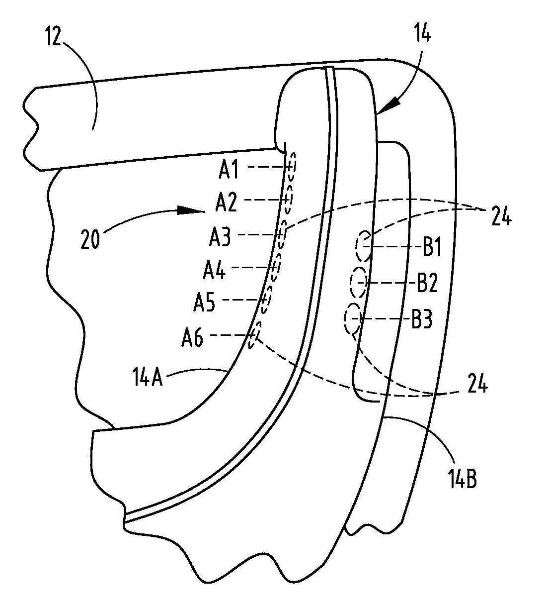
FIG. 2 is an enlarged side view of the door handle showing the door latch assembly on the grip portion of the door handle;
FIG. 3 is an enlarged partial view of the handle grip portion further illustrating an operator hand gripping the grip portion to unlatch the door;
FIG. 4 is an enlarged cross-sectional view taken through the door handle further illustrating the array of proximity sensors and corresponding activation fields;
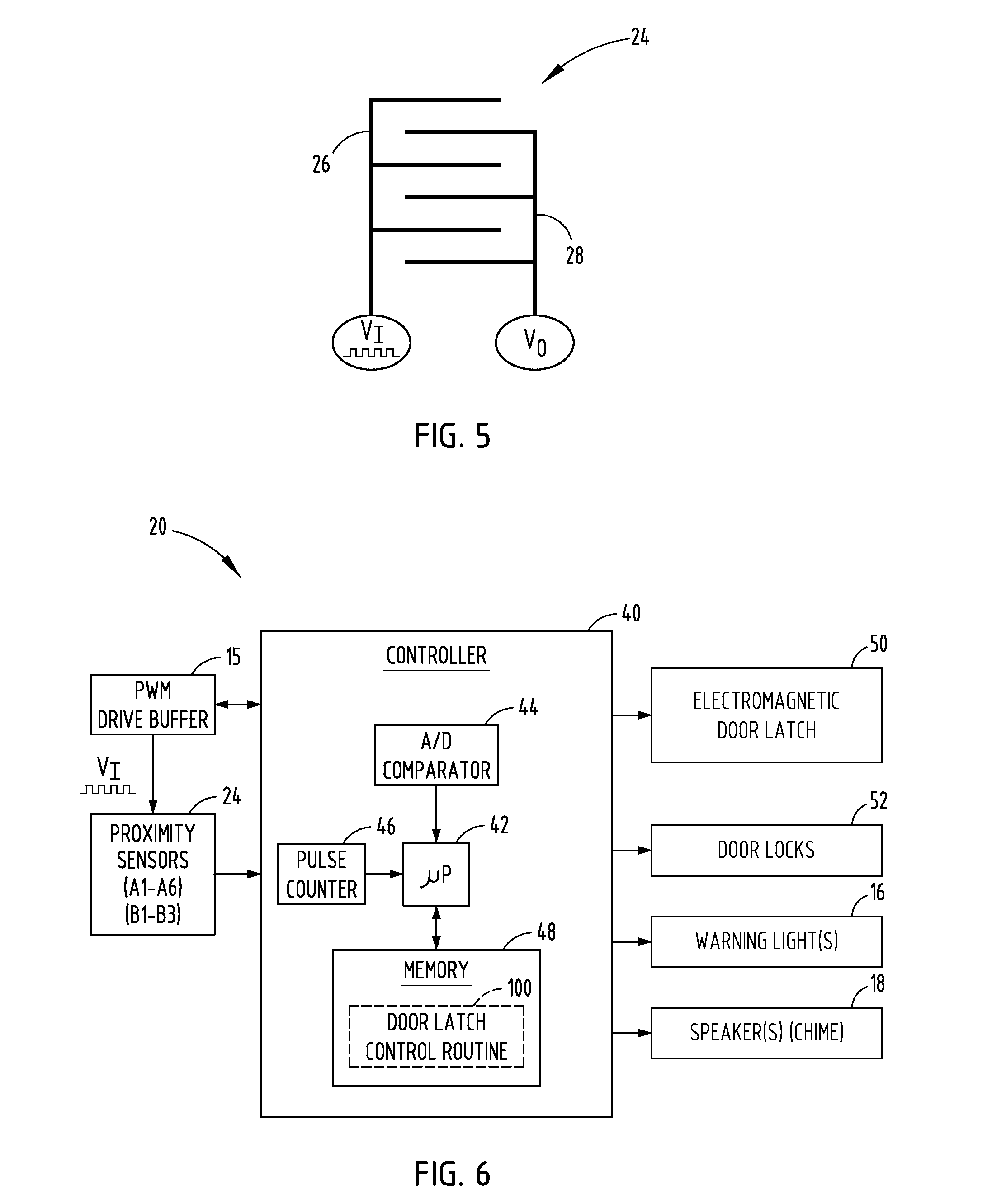
FIG. 5 is a schematic diagram of a capacitive sensor employed in each of the proximity capacitive sensors shown in FIGS. 1-4;
FIG. 6 is a block diagram illustrating the door latch assembly, according to one embodiment; and
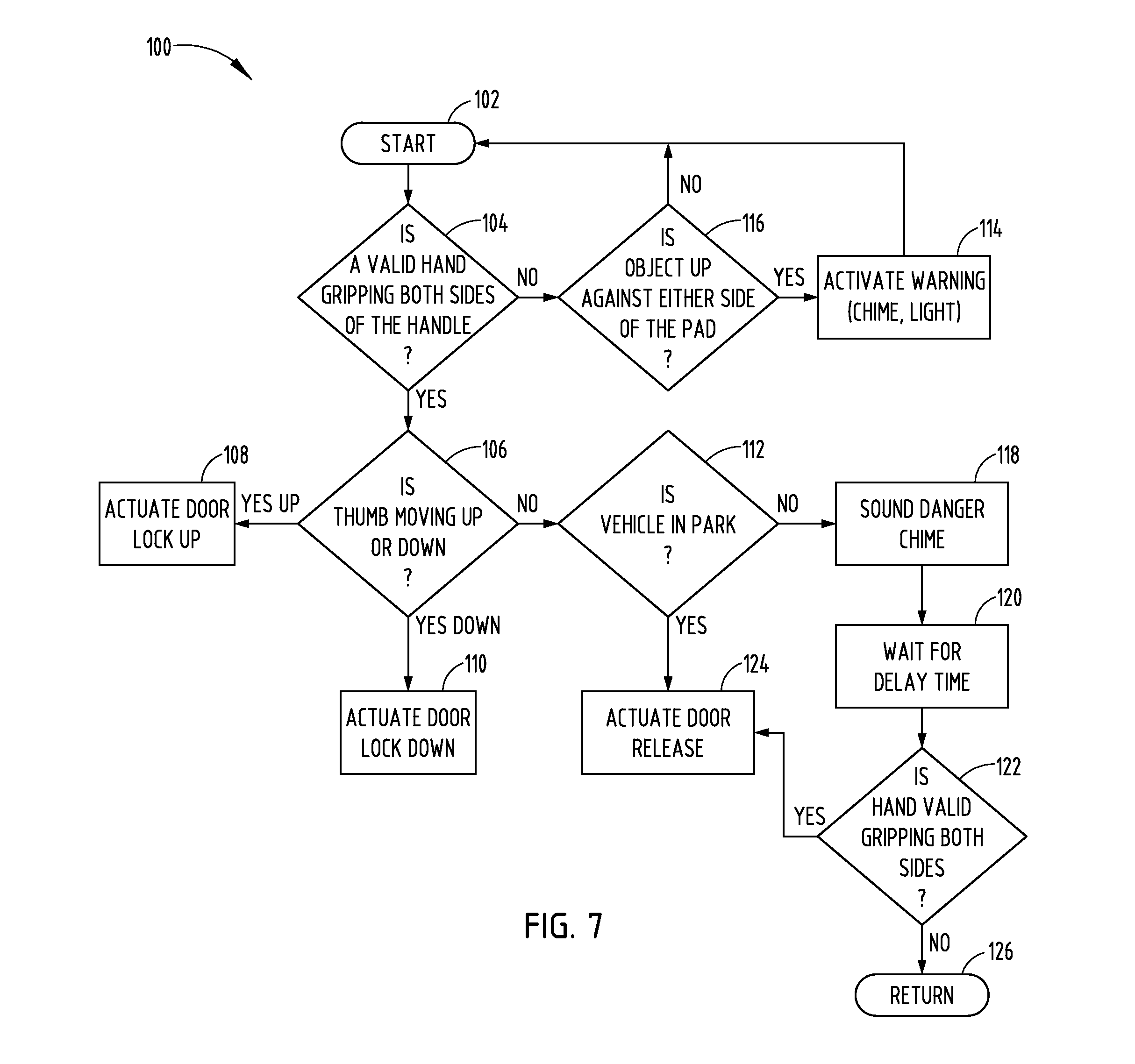
FIG. 7 is a flow diagram illustrating a routine for activating the vehicle door latch assembly, according to one embodiment.
DETAILED DESCRIPTION OF THE PREFERRED EMBODIMENTS
As required, detailed embodiments of the present invention are disclosed herein; however, it is to be understood that the disclosed embodiments are merely exemplary of the invention that may be embodied in various and alternative forms. The figures are not necessarily to a detailed design; some schematics may be exaggerated or minimized to show function overview. Therefore, specific structural and functional details disclosed herein are not to be interpreted as limiting, but merely as a representative basis for teaching one skilled in the art to variously employ the present invention.
Referring to FIGS. 1 and 2, an interior of an automotive vehicle 10 is generally illustrated having a passenger compartment and a vehicle door 12 that may be in the closed position as shown in FIG. 1 or may pivot about hinge assemblies (not shown) to an open position to allow access to the passenger compartment. The door 12 has a handle 14 with a grip portion that allows an operator's hand to grip the handle 14 to forcibly swing the door 12 between open and closed positions. The door 12 also includes a latch assembly 20 for latching the door 12 in the closed position to maintain the door closed and for unlatching the door to allow the door to open to an open position. The latch assembly 20 includes an actuatable latch such as an electromagnetic actuated latch 50 that changes the position of the latch between latched and unlatched positions in response to a control signal. While the vehicle 10 is shown having a front driver side door 12, it should be appreciated that the vehicle may be equipped with a plurality of doors each employing the latch assembly 20 as described herein.
The latch assembly 20 employs a plurality of proximity sensors 24 on the grip portion of the handle 14 to allow an operator to actuate the latch 50 to the unlatched position to release the door and allow the door to open. Included are at least first and second proximity sensors on first and second sides of the door handle for sensing an object, such as an operator's hand gripping the handle. Control circuitry activates the latch via a control signal to unlatch the door 12 based on an object sensed with both the first and second proximity sensors 24. As such, the first and second proximity sensors 24 operate together as a proximity switch to switch the latch 50 to the unlatched position when both the first and second proximity sensors detect an adult hand gripping the handle. Additionally, the proximity sensors 24 may be employed to allow an operator to lock and unlock the latch assembly 20 as described herein.
The vehicle 10 further includes one or more warning lights 16, such as light 16 forward of the driver seat shown in the A-pillar in FIG. 1. Warning light 16 may serve as a visual indication of a sensed condition of the proximity sensors such as to indicate an inadvertent contact of an object on one of the first and second sensors. Additionally, one or more audio speakers 18 are provided in the vehicle to provide a chime output warning to provide a sound indication to alert the passenger(s) of an inadvertent contact of an object on one of the sensors as described herein and to alert the driver or occupant of an anticipated activation of the latch when the vehicle is not in park or is in motion.
Referring to FIGS. 2-4, the handle 14 employing the latch assembly 20 is further illustrated having a plurality of proximity sensors 24, also labeled and referred to as first proximity sensors A1-A6 and second proximity sensors B1-B3 arranged on first and second sides 14A and 14B of the grip portion of the handle 14. In one embodiment, a first linear array of proximity sensors A1-A6 are arranged on a first side of the handle 14 and a second linear array of proximity sensors B1-B3 are arranged on a second opposite side of the handle 14. The first array of proximity sensors A1-A6 extends vertically on one side 14A and the second array of proximity sensors B1-B3 extends vertically on the opposite side 14B. The first and second arrays of proximity sensors A1-A6 and B1-B3 are of a size and positioned so as to be engaged by an operator's hand 60 as seen in FIG. 3. As an operator's hand 60 engages and grips the handle 14, the thumb and palm of the hand 60 come into contact or close proximity to one or more of the first array of proximity sensors A1-A6 and the fingers wrap around the handle 14 such that the fingers at an end closer to the proximal tip thereof come into contact or close proximity to the second array of proximity sensors B1-B3. The proximity sensors A1-A6 and B1-B3 thereby detect the simultaneous presence of an operator's hand on both first and second sides 14A and 14B of the handle 14 which is indicative of an operator gripping the handle 14 so as to initiate a latch open activation command to unlatch the latch and thereby releases the door such that the door may open.
In the embodiment shown, the first array of proximity sensors A1-A6 include six sensors and the second array of proximity sensors B1-B3 includes three sensors; however, it should be appreciated that one or more sensors may be employed in each of the first and second arrays of proximity sensors. Additionally, it should be appreciated that the first array of first proximity sensors A1-A6 and the second array of second proximity sensors B1-B3 are on opposite sides 14A and 14B of the handle 14, according to one embodiment. However, the first and second array of proximity sensors may be provided on different sides of the handle where the first side is at an angle greater than ninety degrees (90.degree.) relative to the second side according to other embodiments. It should further be appreciated that the handle 14 and the proximity sensors 24 may be oriented in other directions other than the generally vertical orientation shown herein. It should be appreciated that by applying a second array of proximity sensors B1-B3 on the back side of the door handle in addition to the first array of proximity sensors A1-A6 on the front side of the door handle is achieved with minimal extra costs since both arrays of proximity sensors may be electrically coupled to shared control circuitry and processed together therewith.
The proximity sensors 24 are shown and described herein as capacitive sensors, according to one embodiment. Each proximity sensor 24 includes at least one proximity sensor that provides a sense activation field to sense contact or close proximity (e.g., within one millimeter) of an object, such as the hand (e.g., palm or finger(s)) of an operator in relation to the one or more proximity sensors. Thus, the first and second arrays of capacitive sensors operate as a capacitive switch. The proximity sensors 24 may also detect a swiping motion by the hand of the operator such as a swipe of the thumb or other finger. Thus, the sense activation field of each proximity sensor 24 is a capacitive field in the exemplary embodiment and the user's hand including the palm, thumb and other fingers have electrical conductivity and dielectric properties that cause a change or disturbance in the sense activation field as should be evident to those skilled in the art. However, it should also be appreciated by those skilled in the art that additional or alternative types of proximity sensors can be used, such as, but not limited to, inductive sensors, optical sensors, temperatures sensors, resistive sensors, the like, or a combination thereof. Exemplary proximity sensors are described in the Apr. 9, 2009, ATMEL.RTM. Touch Sensors Design Guide, 10620 D-AT42-04/09, the entire reference hereby being incorporated herein by reference.
Referring to FIG. 4, the door handle 14 is shown having the capacitive sensors A1-A6 and B1-B3 formed on the outer surface of an inner substrate 30 of handle 14. Alternatively, the sensors could be formed on the inner surface of an outer covering layer 32 overlaying the inner substrate 30. According to one embodiment, each of the proximity sensors 24 may be formed by printing conductive ink onto the outer surface of the inner substrate 30 which provides the support for the handle 14 such that a user is able to grip the handle 14 and push the handle 14 to open the door 12 or pull the handle 14 to close the door 12. The door handle 14 should be sufficiently rigid and strong to allow an operator to easily swing the door 14 between open and closed positions.
One example of the printed ink proximity sensor 24 is shown in FIG. 5 having a drive electrode 26 and a receive electrode 28 each having interdigitated fingers for generating a capacitive field. It should be appreciated that each of the proximity sensors 24 may be otherwise formed such as by assembling a preformed conductive circuit trace onto a substrate according to other embodiments. The drive electrode 26 receives square wave drive pulses applied at voltage V.sub.I. The receive electrode 28 has an output for generating an output voltage V.sub.O. It should be appreciated that the electrodes 26 and 28 may be arranged in various other configurations for generating the capacitive field as the activation field.
In the embodiment shown and described herein, the drive electrode 26 of each proximity sensor 24 is applied with voltage input V.sub.I as square wave pulses having a charge pulse cycle sufficient to charge the receive electrode 28 to a desired voltage. The receive electrode 28 thereby serves as a measurement electrode. In the embodiment shown, adjacent sense activation fields 70A or 70B generated by adjacent proximity sensors 24 overlap, however, more or less overlap may exist according to other embodiments. When a user or operator, such as the user's hand or thumb or other finger(s), enters an activation field, the latch assembly 20 detects the disturbance caused by the hand or fingers to the activation field and determines whether the disturbance in both activation fields 70A and 70B is sufficient to activate a door unlatch command. The disturbance of each activation field is detected by processing the charge pulse signal associated with the corresponding signal channel. When the user's hand or fingers enters the activation fields 70A or 70B generated by the first and second arrays of sensors A1-A6 and B1-B3, the latch assembly 20 detects the disturbance of each contacted activation field via separate signal channels. Each proximity sensor 24 may have its own dedicated signal channel generating charge pulse counts which may be processed.
Each of the first and second capacitive sensors A1-A6 and B1-B3 is shown generating a sense activation field 70A or 70B. The sense activation fields 70A and 70B generated by each individual sensor in each array are shown slightly overlapping, however, it should be appreciated that the activation fields may be smaller or larger and may overlap more or less depending on the sensitivity of the individual fields. By employing a plurality of activation fields on one or both sides of the handle 14, the size and shape of the hand gripping the handle 14 may be determined based on the size of the object being greater than a predetermined size. The size and shape of the hand can be determined based on the number of sensors contacted and/or amplitude of the activation fields. This enables the latch assembly 20 to determine whether an adult or a child is gripping the handle 14 such that activation of the latch may be prevented when a small handle indicative of a child is determined to be gripping the handle and allowed only when a large hand indicative of an adult is determined to be gripping the handle.
In addition, a gesture or swipe motion of the hand, such as a swipe or gesture motion of one or more of the thumb or other fingers may be determined by employing the plurality of capacitive sensors in one or more of the linear arrays. The operator may move one of the digits, such as the thumb, downward which may be sensed with sequential detection by the plurality of capacitive sensors A1-A6 as the thumb passes through each of the sensor activation fields 70A-70F sequentially to initiate a door lock command to lock the latch in the closed or latched position which prevents the door from opening. Contrarily, a digit, such as the thumb, may be moved upward and detected sequentially by the capacitive sensors 70A-70F indicative of a command to unlock the latch to allow the latch assembly to move to the unlatched position to thereby allow the door to be opened. Similarly, other digits or movement of the hand in general may be employed to move up or down and be detected as a swipe or gesture to initiate lock and unlock commands for the latch assembly 20.
Referring to FIG. 6, the proximity sensor activated latch assembly 20 is illustrated according to one embodiment. The plurality of proximity sensors 24 in sensor arrays A1-A6 and B1-B3 are shown providing inputs to a controller 40, such as a microcontroller. The controller 40 may include control circuitry, such as a microprocessor 42 and memory 48. The control circuitry may include sense control circuitry processing the activation field signal associated with each proximity sensor 24 to sense user activation of each sensor by comparing the activation field signal to one or more thresholds pursuant to one or more control routines. It should be appreciated that other analog and/or digital control circuitry may be employed to process each activation field signal, determine user activation, and initiate an action. The controller 40 may employ a QMatrix acquisition method available by ATMEL.RTM., according to one embodiment. The ATMEL acquisition method employs a WINDOWS.RTM. host C/C++ compiler and debugger WinAVR to simplify development and testing the utility Hawkeye that allows monitoring in real-time the internal state of critical variables in the software as well as collecting logs of data for post-processing.
The controller 40 provides an output signal to one or more devices that are configured to perform dedicated actions responsive to detected activation of the proximity sensors on the door handle. The one or more devices may include an electromagnetic door latch 50 that is actuatable to move the latch to a first position or latch position to keep the door closed or to a second or unlatch position to allow the door to open. The electromagnetic door latch 50 may include a conventional electromagnetic actuated latch that moves the latch 50 between the first and second positions based on a control signal from the controller 40. It should be appreciated that other actuatable latches may be employed to move the latch 50 between the first and second positions, such as a pneumatic latch assembly, a motor, or other electrically activated mechanism.
The controller 40 also outputs a control signal to the door lock 52 to activate the door lock between locked and unlocked positions. The electromagnetic latch 50 may be operatively coupled to the door lock 52. When the door lock 52 is in the locked state, the electromagnetic door latch 50 is prevented from moving to the unlatch position. The electromagnetic door latch 50 may only unlatch to the unlatched position when the door lock 52 is in the unlocked position.
The controller 40 further provides output signals to one or more warning lights 16. The warning lights may include one or more LEDs or other light sources at a location visible to the occupant, such as a driver of the vehicle. The warning light(s) may be located in the A-pillar as shown in FIG. 1, or at other suitable locations. Additionally, controller 40 provides an output signal to one or more audio speakers to provide an audible chime sound indicative of a warning. The one or more of the warning lights 16 and speakers 18 may serve as warning indicators to the passengers in the vehicle when an object is detected in close proximity to the proximity sensors such as an inadvertent contact with one sensor or sensor array. The one or more warning lights 16 and speakers 18 may also serve as warning indicators when a potential door unlatch command is detected while the vehicle is not in park and may be moving. The warning may be followed by a time delay such as three seconds prior to unlatching the latch, thereby giving the operator time to consider the intended command.
The controller 40 is further shown having an analog to digital (A/D) comparator 44 coupled to the microprocessor 42. The A/D comparator 44 receives the voltage output V.sub.O from each of the proximity sensors 24, converts the analog signal to a digital signal, and provides the digital signal to the microprocessor 42. Additionally, controller 40 includes a pulse counter 46 coupled to the microprocessor 42. The pulse counter 46 counts the charge signal pulses that are applied to each drive electrode of each proximity sensor, performs a count of the pulses needed to charge the capacitor until the voltage output V.sub.O reaches a predetermined voltage, and provides the count to the microprocessor 42. The pulse count is indicative of the change in capacitance of the corresponding capacitive sensor. The controller 40 is further shown communicating with a pulse width modulated drive buffer 15. The controller 40 provides a pulse width modulated signal to the pulse width modulated drive buffer 15 to generate a square wave pulse train V.sub.I which is applied to each drive electrode of each proximity sensor 24. The controller 40 processes one or more control routines, shown in one embodiment including door latch control routine 100 stored in memory to monitor and make a determination as to activation of one of the proximity switches.
The door latch control routine 100 processes the various proximity sensors 24 and performs a method of sensing user input commanded on each of the proximity sensors and activating control of the latch assembly. Method 100 begins at step 102 and proceeds to decision step 104 to determine if a valid hand gripping is detected on both sides of the handle with the first and second proximity sensors. A valid hand grip may be detected when an object of a sufficient size greater than a predetermined size is detected on both sides of the grip portion of the handle. If a valid hand gripping is detected on the handle by the sensors, method 100 proceeds to decision step 106 to determine if the thumb or other digit on the hand is moving up or down. If the thumb or other digit of the hand is determined to be moving up, method 100 proceeds to step 108 to actuate the door lock up which is indicative of a door unlock command that unlocks the door lock to allow the latch assembly to activate the latch to the door open position. If the thumb or other digit is determined to be moving down, then method 100 proceeds to step 110 to actuate the door lock down which is indicative of a door lock command to prevent the latch from opening. If neither the thumb nor other digit is moving up or down, method 100 proceeds to step 112 to determine if the vehicle is in the park state which is indicative that the vehicle may be moving. The park state may be determined by the vehicle transmission or by vehicle speed. If the vehicle is in park, method 100 proceeds to step 124 to actuate the door latch to release to thereby allow the door to open. If the vehicle is not in park, method 100 activates a sound danger chime at step 118 to notify the occupants that the vehicle may still be moving at the time that a potential door latch release command is detected. Method 100 then waits for a delay time, such as three seconds before allowing the door latch to be released at step 124. The time delay thereby provides the operator sufficient time to disengage gripping of the handle if door actuation of the latch assembly is no longer the intended command. As such, method 100 will first determine if a valid hand gripping is detected on both sides at step 122 before actuating the door latch release to the unlatched position.
If a valid hand gripping on both sides of the handle is not detected at step 104, method 100 proceeds to decision step 116 to determine if an object is up against either side of the pad and, if so, activates a warning chime and/or light at step 114. Accordingly, if an object inadvertently is in close proximity to one or more of the capacitive sensors, a warning light or sound indicator is provided to the operator such that the operator may move the object from the capacitive sensors and not inadvertently release the latch and open the door.
Accordingly, the door latch assembly method advantageously allow for activation of the latch to unlatch the door based on an object sensed with first and second proximity sensors on first and second sides of the door handle. The system and method advantageously allows a user to effectively open the vehicle door without having to actuate a mechanical input lever, and thereby providing for a robust door release latch having fewer moving parts and which is cost-effective and easy to operate.
It is to be understood that variations and modifications can be made on the aforementioned structure without departing from the concepts of the present invention, and further it is to be understood that such concepts are intended to be covered by the following claims unless these claims by their language expressly state otherwise.
* * * * *
References
D00000
D00001
D00002
D00003
D00004
XML
uspto.report is an independent third-party trademark research tool that is not affiliated, endorsed, or sponsored by the United States Patent and Trademark Office (USPTO) or any other governmental organization. The information provided by uspto.report is based on publicly available data at the time of writing and is intended for informational purposes only.
While we strive to provide accurate and up-to-date information, we do not guarantee the accuracy, completeness, reliability, or suitability of the information displayed on this site. The use of this site is at your own risk. Any reliance you place on such information is therefore strictly at your own risk.
All official trademark data, including owner information, should be verified by visiting the official USPTO website at www.uspto.gov. This site is not intended to replace professional legal advice and should not be used as a substitute for consulting with a legal professional who is knowledgeable about trademark law.