Adjustable output solid-state lamp with security features
Reed , et al. December 30, 2
U.S. patent number 8,922,124 [Application Number 13/679,687] was granted by the patent office on 2014-12-30 for adjustable output solid-state lamp with security features. This patent grant is currently assigned to Express Imaging Systems, LLC. The grantee listed for this patent is Express Imaging Systems, LLC. Invention is credited to Dale H. DeGraff, William G. Reed.


| United States Patent | 8,922,124 |
| Reed , et al. | December 30, 2014 |
| **Please see images for: ( Certificate of Correction ) ** |
Adjustable output solid-state lamp with security features
Abstract
Disclosed herein is a remotely adjustable lighting system with security features. The lighting system includes a lamp (e.g., luminaire) which carries solid-state light sources and a sensor. The solid-state light sources emit visible light at an adjustable output intensity. The sensor is responsive to line-of-sight wireless signals, and the lamp increases and decreases the output intensity of the light sources in response to output signals of the sensor. The lamp provides security features by selectively accepting and rejecting instructions carried by the line-of-sight wireless signals to vary the output intensity of the light sources.
| Inventors: | Reed; William G. (Seattle, WA), DeGraff; Dale H. (Brier, WA) | ||||||||||
|---|---|---|---|---|---|---|---|---|---|---|---|
| Applicant: |
|
||||||||||
| Assignee: | Express Imaging Systems, LLC
(Seattle, WA) |
||||||||||
| Family ID: | 48430181 | ||||||||||
| Appl. No.: | 13/679,687 | ||||||||||
| Filed: | November 16, 2012 |
Prior Publication Data
| Document Identifier | Publication Date | |
|---|---|---|
| US 20130141010 A1 | Jun 6, 2013 | |
Related U.S. Patent Documents
| Application Number | Filing Date | Patent Number | Issue Date | ||
|---|---|---|---|---|---|
| 61561616 | Nov 18, 2011 | ||||
| Current U.S. Class: | 315/152; 315/159; 315/308; 315/294; 315/360; 315/320; 362/276 |
| Current CPC Class: | H05B 45/14 (20200101); H05B 47/165 (20200101); Y10T 29/49117 (20150115); H05B 47/10 (20200101); Y02B 20/00 (20130101) |
| Current International Class: | H05B 37/02 (20060101) |
| Field of Search: | ;315/86,291,294,307,297,360,112,132,292,293,308,152,159,320 ;362/276 |
References Cited [Referenced By]
U.S. Patent Documents
| 4153927 | May 1979 | Owens |
| 4237377 | December 1980 | Sansum |
| 5086379 | February 1992 | Denison et al. |
| 5160202 | November 1992 | Legare |
| 5230556 | July 1993 | Canty et al. |
| 5276385 | January 1994 | Itoh et al. |
| 5343121 | August 1994 | Terman et al. |
| 5349505 | September 1994 | Poppenheimer |
| 5450302 | September 1995 | Maase et al. |
| 5561351 | October 1996 | Vrionis et al. |
| 5589741 | December 1996 | Terman et al. |
| 5808294 | September 1998 | Neumann |
| 6111739 | August 2000 | Wu et al. |
| 6612720 | September 2003 | Beadle |
| 6753842 | June 2004 | Williams et al. |
| 6828911 | December 2004 | Jones et al. |
| 6841947 | January 2005 | Berg-johansen |
| 6902292 | June 2005 | Lai |
| 7019276 | March 2006 | Cloutier et al. |
| 7066622 | June 2006 | Alessio |
| 7122976 | October 2006 | Null et al. |
| 7188967 | March 2007 | Dalton et al. |
| 7196477 | March 2007 | Richmond |
| 7239087 | July 2007 | Ball |
| 7252385 | August 2007 | Engle et al. |
| 7258464 | August 2007 | Morris et al. |
| 7281820 | October 2007 | Bayat et al. |
| 7314291 | January 2008 | Tain et al. |
| 7317403 | January 2008 | Grootes et al. |
| 7322714 | January 2008 | Barnett et al. |
| 7339323 | March 2008 | Bucur |
| 7339471 | March 2008 | Chan et al. |
| 7405524 | July 2008 | Null et al. |
| 7438440 | October 2008 | Dorogi |
| 7440280 | October 2008 | Shuy |
| 7468723 | December 2008 | Collins |
| 7524089 | April 2009 | Park |
| 7538499 | May 2009 | Ashdown |
| 7578596 | August 2009 | Martin |
| 7578597 | August 2009 | Hoover et al. |
| 7627372 | December 2009 | Vaisnys et al. |
| 7631324 | December 2009 | Buonasera et al. |
| 7633463 | December 2009 | Negru |
| 7677753 | March 2010 | Wills |
| 7688002 | March 2010 | Ashdown et al. |
| 7688222 | March 2010 | Peddie et al. |
| 7703951 | April 2010 | Piepgras et al. |
| 7804200 | September 2010 | Flaherty |
| 7834922 | November 2010 | Kurane |
| 7932535 | April 2011 | Mahalingam et al. |
| 7940191 | May 2011 | Hierzer |
| 7952609 | May 2011 | Simerly et al. |
| 7960919 | June 2011 | Furukawa |
| 7985005 | July 2011 | Alexander et al. |
| 8100552 | January 2012 | Spero |
| 8118456 | February 2012 | Reed et al. |
| 8143769 | March 2012 | Li |
| 8174212 | May 2012 | Tziony et al. |
| 2002/0113192 | August 2002 | Antila |
| 2004/0192227 | September 2004 | Beach et al. |
| 2006/0014118 | January 2006 | Utama |
| 2006/0066264 | March 2006 | Ishigaki et al. |
| 2007/0032990 | February 2007 | Williams et al. |
| 2007/0102033 | May 2007 | Petrocy |
| 2008/0018261 | January 2008 | Kastner |
| 2008/0043106 | February 2008 | Hassapis et al. |
| 2008/0130304 | June 2008 | Rash et al. |
| 2008/0266839 | October 2008 | Claypool et al. |
| 2009/0160358 | June 2009 | Leiderman |
| 2009/0161356 | June 2009 | Negley et al. |
| 2009/0167203 | July 2009 | Dahlman et al. |
| 2009/0230883 | September 2009 | Haug |
| 2009/0235208 | September 2009 | Nakayama et al. |
| 2009/0261735 | October 2009 | Sibalich et al. |
| 2009/0268023 | October 2009 | Hsieh |
| 2009/0278479 | November 2009 | Platner et al. |
| 2009/0284155 | November 2009 | Reed et al. |
| 2009/0315485 | December 2009 | Verfuerth et al. |
| 2010/0052557 | March 2010 | Van Der Veen et al. |
| 2010/0090577 | April 2010 | Reed et al. |
| 2010/0096460 | April 2010 | Carlson et al. |
| 2010/0123403 | May 2010 | Reed |
| 2010/0171442 | July 2010 | Draper et al. |
| 2010/0259193 | October 2010 | Umezawa et al. |
| 2010/0271802 | October 2010 | Recker et al. |
| 2010/0277082 | November 2010 | Reed et al. |
| 2010/0295454 | November 2010 | Reed |
| 2010/0295455 | November 2010 | Reed |
| 2010/0295946 | November 2010 | Reed et al. |
| 2011/0001626 | January 2011 | Yip et al. |
| 2011/0006703 | January 2011 | Wu et al. |
| 2011/0026264 | February 2011 | Reed et al. |
| 2011/0175518 | July 2011 | Reed et al. |
| 2011/0221346 | September 2011 | Lee et al. |
| 2011/0251751 | October 2011 | Knight |
| 2011/0310605 | December 2011 | Renn et al. |
| 2012/0001566 | January 2012 | Josefowicz et al. |
| 2012/0169053 | July 2012 | Tchoryk, Jr. et al. |
| 2012/0221154 | August 2012 | Runge |
| 2012/0262069 | October 2012 | Reed |
| 2013/0049613 | February 2013 | Reed |
| 2013/0141000 | June 2013 | Wei et al. |
| 2013/0163243 | June 2013 | Reed |
| 2013/0340353 | December 2013 | Whiting et al. |
| 4001980 | Aug 1990 | DE | |||
| 1 734 795 | Dec 2006 | EP | |||
| 2 883 306 | Sep 2006 | FR | |||
| 6-335241 | Dec 1994 | JP | |||
| 2001-333420 | Nov 2001 | JP | |||
| 2004-279668 | Oct 2004 | JP | |||
| 2004-349065 | Dec 2004 | JP | |||
| 2005-93171 | Apr 2005 | JP | |||
| 2005-198238 | Jul 2005 | JP | |||
| 2005-310997 | Nov 2005 | JP | |||
| 2006-179672 | Jul 2006 | JP | |||
| 2006-244711 | Sep 2006 | JP | |||
| 2008-509538 | Mar 2008 | JP | |||
| 2008-130523 | Jun 2008 | JP | |||
| 2008-159483 | Jul 2008 | JP | |||
| 2008-177144 | Jul 2008 | JP | |||
| 2005078403 | Aug 2005 | KR | |||
| 10-2006-0086254 | Jul 2006 | KR | |||
| 10-2009-0042400 | Apr 2009 | KR | |||
| 10-0935736 | Jan 2010 | KR | |||
| 20-2010-0007230 | Jul 2010 | KR | |||
| 10-1001276 | Dec 2010 | KR | |||
| 10-1044224 | Jun 2011 | KR | |||
| 10-1150876 | May 2012 | KR | |||
| 02/076068 | Sep 2002 | WO | |||
| 03/056882 | Jul 2003 | WO | |||
| 2006/057866 | Jun 2006 | WO | |||
| 2007/036873 | Apr 2007 | WO | |||
| 2008/030450 | Mar 2008 | WO | |||
| 2009/040703 | Apr 2009 | WO | |||
| 2012/006710 | Jan 2012 | WO | |||
| 2012/142115 | Oct 2012 | WO | |||
| 2014/018773 | Jan 2014 | WO | |||
| 2014/039683 | Mar 2014 | WO | |||
| 2014/078854 | May 2014 | WO | |||
Other References
|
"Lcd Backlight I/O Ports and Power Protection Circuit Design," dated May 2, 2011, retrieved Jun. 10, 2011, retrieved from http://www.chipoy.info/gadgets/lcd-backlight-i-o-ports-and-power-pr . . . , 4 pages. cited by applicant . EE Herald, "Devices to protect High brightness LED from ESD," dated Mar. 16, 2009, retrieved Jun. 10, 2011, retrieved from http://www.eeherald.com/section/new-products/np100779.html, 1 page. cited by applicant . International Search Report, mailed Dec. 13, 2010 for PCT/US2010/035649, 3 pages. cited by applicant . International Search Report, mailed Dec. 15, 2010 for PCT/US2010/035658, 3 pages. cited by applicant . International Search Report, mailed Dec. 28, 2010 for PCT/US2010/035651, 3 pages. cited by applicant . International Search Report, mailed Jul. 9, 2009 for PCT/US2009/043171, 5 pages. cited by applicant . International Search Report, mailed Jun. 21, 2010 for PCT/US2009/064625, 3 pages. cited by applicant . International Search Report, mailed Oct. 8, 2012 for PCT/US2012/033059, 3 pages. cited by applicant . Littelfuse, "Application Note: Protecting LEDs in Product Designs," 2009, 2 pages. cited by applicant . Panasonic Electronic Components, "LED Lighting Solutions," 2009, 6 pages. cited by applicant . Renesas Electronics, "Zener Diodes for Surge Absorption--Applications of high-intensity LED," Apr. 2010, 1 page. cited by applicant . Tyco Electronics, "Circuit Protection," retrieved Jun. 10, 2011, retrieved from http://www.tycoelectronics.com/en/products/circuit-protection.html, 2 pages. cited by applicant . Written Opinion, mailed Dec. 13, 2010 for PCT/US2010/035649, 4 pages. cited by applicant . Written Opinion, mailed Dec. 15, 2010 for PCT/US2010/035658, 3 pages. cited by applicant . Written Opinion, mailed Dec. 28, 2010 for PCT/US2010/035651, 3 pages. cited by applicant . Written Opinion, mailed Jul. 9, 2009 for PCT/US2009/043171, 8 pages. cited by applicant . Written Opinion, mailed Jun. 21, 2010 for PCT/US2009/064625, 5 pages. cited by applicant . Written Opinion, mailed Oct. 8, 2012 for PCT/US2012/033059, 3 pages. cited by applicant . Reed, "Apparatus and Method of Energy Efficient Illumination," U.S. Appl. No. 61/333,983, filed May 12, 2010, 57 pages. cited by applicant . Reed, "Apparatus and Method of Energy Efficient Illumination," U.S. Appl. No. 61/346,263, filed May 19, 2010, 67 pages. cited by applicant . Reed, "Apparatus and Method of Energy Efficient Illumination Using Received Signals," U.S. Appl. No. 13/085,301, filed Apr. 12, 2011, 99 pages. cited by applicant . Reed, "Electronic Control to Regulate Power for Solid-State Lighting and Methods Thereof," U.S. Appl. No. 61/115,438, filed Nov. 17, 2008, 51 pages. cited by applicant . Reed, "Electronic Control to Regulate Power for Solid-State Lighting and Methods Thereof," U.S. Appl. No. 61/154,619, filed Feb. 23, 2009, 62 pages. cited by applicant . Reed, "Electrostatic Discharge Protection for Luminaire," U.S. Appl. No. 13/212,074, filed Aug. 17, 2011, 30 pages. cited by applicant . Reed, "Resonant Network for Reduction of Flicker Perception in Solid State Lighting Systems," U.S. Appl. No. 61/527,029, filed Aug. 24, 2011, 41 pages. cited by applicant . Reed et al., "Apparatus and Method for Schedule Based Operation of a Luminaire," U.S. Appl. No. 13/604,327, filed Sep. 5, 2012, 44 pages. cited by applicant . Reed et al., "Apparatus and Method of Operating a Luminaire," U.S. Appl. No. 13/558,191, filed Jul. 25, 2012, 84 pages. cited by applicant . Reed et al., "Apparatus, Method to Change Light Source Color Temperature With Reduced Optical Filtering Losses," U.S. Appl. No. 13/007,080, filed Jan. 14, 2011, 45 pages. cited by applicant . Reed et al., "Apparatus, Method to Change Light Source Color Temperature With Reduced Optical Filtering Losses," U.S. Appl. No. 61/295,519, filed Jan. 15, 2010, 35 pages. cited by applicant . Reed et al., "Apparatus, Method to Change Light Source Color Temperature With Reduced Optical Filtering Losses," U.S. Appl. No. 61/406,490, filed Oct. 25, 2010, 46 pages. cited by applicant . Reed et al., "Apparatus, Method to Enhance Color Contrast in Phosphor-Based Solid State Lights," U.S. Appl. No. 61/534,722, filed Sep. 14, 2011, 53 pages. cited by applicant . Reed et al., "Electrically Isolated Heat Sink for a Solid-State Light," U.S. Appl. No. 61/229,435, filed Jul. 29, 2009, 29 pages. cited by applicant . Reed et al., "Gas-Discharge Lamp Replacement," U.S. Appl. No. 61/052,924, filed May 13, 2008, 32 pages. cited by applicant . Reed et al., "Gas-Discharge Lamp Replacement With Passive Cooling," U.S. Appl. No. 61/174,913, filed May 1, 2009, 29 pages. cited by applicant . Reed et al., "Long-Range Motion Detection for Illumination Control," U.S. Appl. No. 61/180,017, filed May 20, 2009, 32 pages. cited by applicant . Reed et al., "Low-Profile Pathway Illumination System," U.S. Appl. No. 61/051,619, filed May 8, 2008, 25 pages. cited by applicant . Reed et al., "Low-Profile Pathway Illumination System," Amendment dated Jul. 29, 2011 for U.S. Appl. No. 12/437,472, 19 pages. cited by applicant . Reed et al., "Low-Profile Pathway Illumination System," Notice of Allowance dated Oct. 14, 2011 for U.S. Appl. No. 12/437,472, 9 pages. cited by applicant . Reed et al., "Low-Profile Pathway Illumination System," Office Action mailed May 5, 2011 for U.S. Appl. No. 12/437,472, 24 pages. cited by applicant . Reed et al., "Systems and Methods That Employ Object Recognition," U.S. Appl. No. 13/411,321, filed Mar. 2, 2012, 51 pages. cited by applicant . Reed et al., "Turbulent Flow Cooling for Electronic Ballast," U.S. Appl. No. 61/088,651, filed Aug. 13, 2008, 23 pages. cited by applicant . Renn et al., "Solid State Lighting Device and Method Employing Heat Exchanger Thermally Coupled Circuit Board," U.S. Appl. No. 61/357,421, filed Jun. 22, 2010, 49 pages. cited by applicant . International Search Report, mailed Sep. 30, 2011 for PCT/US2011/021359, 3 pages. cited by applicant . Reed, "Electrostatic Discharge Protection for Luminaire," Office Action mailed Mar. 15, 2013 for U.S. Appl. No. 13/212,074, 11 pages. cited by applicant . Written Opinion mailed Sep. 30, 2011 for PCT/US2011/021359, 4 pages. cited by applicant . International Search Report, mailed Feb. 27, 2013 for PCT/US2012/065476, 3 pages. cited by applicant . Written Opinion, mailed Feb. 27, 2013 for PCT/US2012/065476, 8 pages. cited by applicant . Fairchild Semiconductor, "LED Application Design Guide Using Half-Bridge LLC Resonant Converter for 100W Street Lighting," AN-9729, Fairchild Semiconductor Corporation, Rev. 1.0.0, Mar. 22, 2011, 17 pages. cited by applicant . Huang, "Designing an LLC Resonant Half-Bridge Power Converter," 2010 Texas Instruments Power Supply Design Seminar, SEM1900, Topic 3, TI Literature No. SLUP263, Copyright 2010, 2011, Texas Instruments Incorporated, 28 pages. cited by applicant . International Search Report, mailed Jan. 14, 2013 for PCT/US2012/052009, 3 pages. cited by applicant . Kadirvel et al., "Self-Powered, Ambient Light Sensor Using bq25504," Texas Instruments, Application Report, SLUA629--Jan. 2012, 6 pages. cited by applicant . Reed et al., "Adjustable Output Solid-State Lamp With Security Features," U.S. Appl. No. 61/561,616, filed Nov. 18, 2011, 33 pages. cited by applicant . Reed et al., "Long-Range Motion Detection for Illumination Control," Office Action mailed Dec. 21, 2012, for U.S. Appl. No. 12/784,080, 26 pages. cited by applicant . Reed et al., "Long-Range Motion Detection for Illumination Control," Amendment filed Apr. 22, 2013, for U.S. Appl. No. 12/784,080, 17 pages. cited by applicant . Reed et al., "Long-Range Motion Detection for Illumination Control," Office Action mailed Jul. 22, 2013, for U.S. Appl. No. 12/784,080, 29 pages. cited by applicant . Reed et al., "Long-Range Motion Detection for Illumination Control," Amendment filed Sep. 27, 2013, for U.S. Appl. No. 12/784,080, 20 pages. cited by applicant . Reed et al., "Remotely Adjustable Solid-State Lamp," U.S. Appl. No. 61/641,781, filed May 2, 2012, 65 pages. cited by applicant . Reed et al., "Remotely Adjustable Solid-State Lamp," U.S. Appl. No. 13/875,130, filed May 1, 2013, 65 pages. cited by applicant . Reed, "Adjustable Output Solid-State Lighting Device," U.S. Appl. No. 61/567,308, filed Dec. 6, 2011, 49 pages. cited by applicant . Reed, "Apparatus and Method of Energy Efficient Illumination," Office Action mailed Dec. 5, 2012, for U.S. Appl. No. 12/784,091, 18 pages. cited by applicant . Reed, "Apparatus and Method of Energy Efficient Illumination," Amendment filed Apr. 4, 2013, for U.S. Appl. No. 12/784,091, 15 pages. cited by applicant . Reed, "Apparatus and Method of Energy Efficient Illumination," Office Action mailed Apr. 24, 2013, for U.S. Appl. No. 12/784,091, 12 pages. cited by applicant . Reed, "Apparatus and Method of Energy Efficient Illumination," Amendment filed May 14, 2013, for U.S. Appl. No. 12/784,091, 9 pages. cited by applicant . Reed, "Apparatus and Method of Energy Efficient Illumination," Notice of Allowance mailed May 23, 2013, for U.S. Appl. No. 12/784,091, 6 pages. cited by applicant . Reed, "Apparatus and Method of Energy Efficient Illumination," Office Action mailed Dec. 5, 2012, for U.S. Appl. No. 12/784,093, 13 pages. cited by applicant . Reed, "Apparatus and Method of Energy Efficient Illumination," Amendment filed Apr. 2, 2013, for U.S. Appl. No. 12/784,093, 13 pages. cited by applicant . Reed, "Apparatus and Method of Energy Efficient Illumination," Notice of Allowance mailed Apr. 12, 2013, for U.S. Appl. No. 12/784,093, 9 pages. cited by applicant . Reed, "Apparatus and Method of Energy Efficient Illumination," U.S. Appl. No. 13/943,537, filed Jul. 16, 2013, 67 pages. cited by applicant . Reed, "Apparatus and Method of Energy Efficient Illumination Using Received Signals," Office Action mailed Oct. 1, 2013, for U.S. Appl. No. 13/085,301, 11 pages. cited by applicant . Reed, "Electronic Control to Regulate Power for Solid-State Lighting and Methods Thereof," Office Action mailed Feb. 28, 2013, for U.S. Appl. No. 12/619,535, 17 pages. cited by applicant . Reed, "Electronic Control to Regulate Power for Solid-State Lighting and Methods Thereof," Amendment filed May 24, 2013, for U.S. Appl. No. 12/619,535, 21 pages. cited by applicant . Reed, "Electronic Control to Regulate Power for Solid-State Lighting and Methods Thereof," Office Action mailed Jul. 30, 2013, for U.S. Appl. No. 12/619,535, 15 pages. cited by applicant . Reed, "Electronic Control to Regulate Power for Solid-State Lighting and Methods Thereof," Amendment filed Oct. 30, 2013, for U.S. Appl. No. 12/619,535, 5 pages. cited by applicant . Reed, "Electrostatic Discharge Protection for Luminaire," Amendment filed Jun. 17, 2013, for U.S. Appl. No. 13/212,074, 11 pages. cited by applicant . Reed, "Electrostatic Discharge Protection for Luminaire," Notice of Allowance mailed Sep. 12, 2013, for U.S. Appl. No. 13/212,074, 6 pages. cited by applicant . Reed, "Luminaire With Ambient Sensing and Autonomous Control Capabilities," U.S. Appl. No. 61/728,150, filed Nov. 19, 2012, 83 pages. cited by applicant . Reed, "Luminaire With Ambient Sensing and Autonomous Control Capabilities," U.S. Appl. No. 13/786,332, filed Mar. 5, 2013, 86 pages. cited by applicant . Reed, "Luminaire With Atmospheric Electrical Activity Detection and Visual Alert Capabilities," U.S. Appl. No. 61/649,159, filed Aug. 28, 2012, 52 pages. cited by applicant . Reed, "Luminaire With Atmospheric Electrical Activity Detection and Visual Alert Capabilities," U.S. Appl. No. 13/786,114, filed Mar. 5, 2013, 52 pages. cited by applicant . Reed, "Luminaire With Switch-Mode Converter Power Monitoring," U.S. Appl. No. 61/723,675, filed Nov. 7, 2012, 73 pages. cited by applicant . Reed, "Luminaire With Switch-Mode Converter Power Monitoring," U.S. Appl. No. 14/074,166, filed Nov. 7, 2013, 73 pages. cited by applicant . Reed, "Photocontrol for Luminaire Consumes Very Low Power," U.S. Appl. No. 61/849,841, filed Jul. 24, 2013, 41 pages. cited by applicant . Reed, "Resonant Network for Reduction of Flicker Perception in Solid State Lighting Systems," Notice of Allowance mailed Sep. 30, 2013, for U.S. Appl. No. 13/592,590, 9 pages. cited by applicant . Reed, "Solid State Hospitality Lamp," U.S. Appl. No. 61/692,619, filed Aug. 23, 2012, 32 pages. cited by applicant . Reed, "Solid State Hospitality Lamp," U.S. Appl. No. 13/973,696, filed Aug. 22, 2013, 32 pages. cited by applicant . Reed, "Solid State Lighting, Drive Circuit and Method of Driving Same," U.S. Appl. No. 61/640,963, filed May 1, 2012, 24 pages. cited by applicant . Reed, "Solid State Lighting, Drive Circuit and Method of Driving Same," U.S. Appl. No. 13/875,000, filed May 1, 2013, 24 pages. cited by applicant . Written Opinion, mailed Jan. 14, 2013 for PCT/US2012/052009, 5 pages. cited by applicant . International Search Report, mailed Nov. 19, 2013 for PCT/US2013/052092, 4 pages. cited by applicant . International Search Report, mailed Dec. 30, 2013 for PCT/US2013/058266, 3 pages. cited by applicant . Reed, "Apparatus and Method of Energy Efficient Illumination," Office Action mailed Nov. 27, 2013, for U.S. Appl. No. 13/943,537, 8 pages. cited by applicant . Reed, "Apparatus and Method of Energy Efficient Illumination Using Received Signals," Amendment filed Jan. 2, 2014, for U.S. Appl. No. 13/085,301, 26 pages. cited by applicant . Reed, "High Efficiency Power Controller for Luminaire," U.S. Appl. No. 61/905,699, filed Nov. 18, 2013, 5 pages. cited by applicant . Written Opinion, mailed Nov. 19, 2013 for PCT/US2013/052092, 7 pages. cited by applicant . Written Opinion, mailed Dec. 30, 2013 for PCT/US2013/058266, 8 pages. cited by applicant . International Search Report, mailed Feb. 26, 2014, for PCT/US2013/070794, 3 pages. cited by applicant . Poplawski, "Exploring Flicker & LEDs," 2010 DOE SSL Market Introduction Workshop, U.S. Department of Energy, Jul. 22, 2010, 16 pages. cited by applicant . Reed et al., "Apparatus and Method for Schedule Based Operation of a Luminaire," Office Action mailed Mar. 26, 2014, for U.S. Appl. No. 13/604,327, 10 pages. cited by applicant . Reed et al., "Long-Range Motion Detection for Illumination Control," Office Action mailed Jan. 30, 2014, for U.S. Appl. No. 12/784,080, 26 pages. cited by applicant . Reed et al., "Long-Range Motion Detection for Illumination Control," Amendment filed Apr. 28, 2014, for U.S. Appl. No. 12/784,080, 20 pages. cited by applicant . Reed, "Ambient Light Control in Solid State Lamps and Luminaires," U.S. Appl. No. 61/933,733, filed Jan. 30, 2014, 8 pages. cited by applicant . Reed, "Apparatus and Method of Energy Efficient Illumination," Notice of Allowance mailed Apr. 11, 2014, for U.S. Appl. No. 13/943,537, 9 pages. cited by applicant . Reed, "Apparatus and Method of Energy Efficient Illumination Using Received Signals," Office Action mailed Apr. 23, 2014, for U.S. Appl. No. 13/085,301, 12 pages. cited by applicant . Reed, "Electronic Control to Regulate Power for Solid-State Lighting and Methods Thereof," Office Action mailed Mar. 26, 2014, for U.S. Appl. No. 12/619,535, 16 pages. cited by applicant . Reed, "Photocontrol for Luminaire Consumes Very Low Power," U.S. Appl. No. 14/158,630, filed Jan. 17, 2014, 71 pages. cited by applicant . Reed, "Systems, Methods, and Apparatuses for Using a High Current Switching Device As a Logic Level Sensor," U.S. Appl. No. 61/764,395, filed Feb. 13, 2013, 48 pages. cited by applicant . Reed, "Systems, Methods, and Apparatuses for Using a High Current Switching Device as a Logic Level Sensor," U.S. Appl. No. 14/179,737, filed Feb. 13, 2014, 48 pages. cited by applicant . Written Opinion, mailed Feb. 26, 2014, for PCT/US2013/070794, 10 pages. cited by applicant . Reed et al., "Apparatus and Method for Schedule Based Operation of a Luminaire," Amendment filed Jun. 24, 2014, for U.S. Appl. No. 13/604,327, 14 pages. cited by applicant . Reed et al., "Apparatus and Method for Schedule Based Operation of a Luminaire," Notice of Allowance mailed Jul. 7, 2014, for U.S. Appl. No. 13/604,327, 8 pages. cited by applicant . Reed et al., "Long-Range Motion Detection for Illumination Control," Notice Of Allowance mailed Jun. 20, 2014, for U.S. Appl. No. 12/784,080, 7 pages. cited by applicant . Reed, "Apparatus and Method of Energy Efficient Illumination," U.S. Appl. No. 14/329,508, filed Jul. 11, 2014, 61 pages. cited by applicant . Reed, "Apparatus and Method of Energy Efficient Illumination Using Received Signals," Amendment filed Jul. 23, 2014, for U.S. Appl. No. 13/085,301, 12 pages. cited by applicant . Reed, "Electronic Control to Regulate Power for Solid-State Lighting and Methods Thereof," Amendment filed May 27, 2014, for U.S. Appl. No. 12/619,535, 22 pages. cited by applicant . Reed, "Luminaire With Atmospheric Electrical Activity Detection and Visual Alert Capabilities," Notice Of Allowance mailed Jul. 1, 2014, for U.S. Appl. No. 13/786,114, 9 pages. cited by applicant. |
Primary Examiner: Tran; Thienvu
Assistant Examiner: Lo; Christopher
Attorney, Agent or Firm: Seed IP Law Group PLLC
Claims
The invention claimed is:
1. A lighting system for use with lighting fixtures having at least one coupler configured to provide detachable physical and electrical connections therewith, the lighting system comprising: a lamp, including: a number of solid-state light sources; at least one complementary coupler that physically and electrically detachably couples to the coupler of the lighting fixture; at least one sensor responsive to a number of line-of-sight wireless signals to provide a number of wireless sensor output signals representative of the sensed line-of-sight wireless signals; and a set of driver electronics electrically coupled between the complementary coupler of the lamp and the solid-state light sources of the lamp; wherein the driver electronics includes a controller that validates an access identifier encoded in the received number of line-of-sight wireless signals; and wherein, responsive to a successful validation of the access identifier, the controller executes a timer that defines a time period during which the controller is placed in a command mode in which the controller accepts adjustment instructions encoded in the received number of line-of-sight wireless signals.
2. The lighting system of claim 1, further comprising: a remote transmitter having a user interface selectively operable by a user to receive a number of user inputs, the remote transmitter operable to transmit the number of line-of-sight wireless signals in response to the user inputs received via the user interface.
3. The lighting system of claim 2 wherein the line-of-sight wireless signals include adjustment instructions indicative of an adjustment in the amount of light output by the solid-state light sources, and the driver electronics are responsive to the adjustment instructions to vary the amount of light output by the solid-state light sources based on the adjustment instructions.
4. The lighting system of claim 1, further comprising: a memory communicatively coupled to the controller, wherein the controller validates the access identifier against data stored in the memory.
5. The lighting system of claim 4 wherein the memory is writable and data stored therein is user-changeable.
6. The lighting system of claim 1 wherein in response to a validation of the access identifier by the controller, the controller enters a command mode within which the controller is responsive to a number of additional adjustment instructions to vary the output intensity of the solid-state light sources.
7. The lighting system of claim 1 wherein the controller exits the command mode at an expiration of the timer.
8. The lighting system of claim 1 wherein in response to the validation of the access identifier the controller executes a timer, reinitiates the timer on receipt of each additional adjustment instruction, and exits the command mode at an expiration of the timer.
9. The lighting system of claim 1 wherein the driver electronics includes a transformer having a primary and a secondary, the primary electrically coupled to the complementary coupler, and a switch mode power converter electrically coupled to the secondary of the transformer and to the solid-state light sources.
10. The lighting system of claim 1 wherein the lamp takes the form of a luminaire and further includes: a housing physically coupled to the complementary coupler and that at least partially encloses the driver electronics.
11. The lighting system of claim 10 wherein the at least one sensor includes a plurality of sensors recessed into the housing.
12. The lighting system of claim 1 wherein the lamp takes the form of a luminaire and further includes a lens and the solid-state light sources and the at least one sensor are positioned relatively behind the lens with respect to a direction in which light is transmitted by the solid-state light sources.
13. A method of manufacturing a lamp for use with lighting fixtures having at least one coupler configured to provide detachable physical and electrical connections therewith, the method comprising: electrically coupling a complementary coupler of the lamp, that physically and electrically detachably couples to the at least one coupler of the lighting fixture, to a number of solid-state light sources; communicatively coupling a set of driver electronics to at least one sensor that is responsive to a number of line-of-sight wireless signals and that provides a number of wireless sensor output signals representative of the sensed line-of-sight wireless signals; electrically coupling the set of driver electronics between the complementary coupler of the lamp and the solid-state light sources of the lamp to adjust an amount of light output by the solid-state light sources based at least in part on the line-of-sight wireless signals sensed by the at least one sensor; validating, by a controller included in the driver electronics, an access identifier encoded in the line-of-sight wireless signals; and responsive to a successful validation of the access identifier by the controller, executing, by the controller, a timer that defines a time period during which the controller is placed in a command mode in which the controller accepts adjustment instructions encoded in the received number of line-of-sight wireless signals.
14. The method of claim 13, further comprising: physically coupling a housing to the complementary coupler of the lamp; and mounting the at least one sensor to the housing.
15. The method of claim 13, further comprising: positioning the at least one sensor and the solid-state light sources relatively behind a lens with respect to a direction in which light is transmitted from the solid-state light sources.
16. The method of claim 13, further comprising: configuring the set of driver electronics to validate an access identifier encoded in the number of line-of-sight wireless signals; and after the set of driver electronics validates the access identifier, configuring the set of driver electronics to adjust the amount of light output by the solid-state light sources in response to output intensity adjustment instructions encoded in the number of line-of-sight wireless signals.
17. The method of claim 15, further comprising: communicatively coupling a rewriteable memory to the set of driver electronics; and storing a user-changeable master access identifier in the rewriteable memory against which the set of driver electronics validates the encoded access identifier.
18. The method of claim 17, further comprising: electronically storing a set of adjustment instructions in the lamp that are indicative of output intensity adjustment instructions encodable in the number of line-of-sight wireless signals; and configuring the set of driver electronics to adjust the amount of light output by the solid-state light sources in response to comparing the set of adjustment instructions to the output intensity adjustment instructions encoded in the number of line-of-sight wireless signals.
19. A method of operating a solid-state lamp for use with lighting fixtures having at least one coupler configured to provide detachable physical and electrical connections therewith, comprising: physically and electrically coupling a complementary coupler of the solid-state lamp to the at least one coupler of the fixture to transfer power to the solid-state lamp; receiving a number of wireless line-of-sight signals with a sensor that is electrically coupled to the solid-state lamp and that is carried by the solid-state lamp; validating, by a controller included in the driver electronics, an access identifier encoded in the received number of line-of-sight wireless signals; and responsive to the successful validation of the received access identifier, executing a timer that defines a time period during which the controller is placed in a command mode in which the controller accepts output intensity adjustment commands encoded in the received number of line-of-sight wireless signals; and adjusting, with a set of driver electronics that are carried by the lamp, an amount of light output by the solid-state lamp in response to the output intensity adjustment commands encoded in the number of wireless line-of-sight signals.
20. The method of claim 19, further comprising: entering a command mode in response to validating, with the set of driver electronics, an access identifier embedded in the wireless line-of-sight signals; receiving an additional number of wireless line-of-sight signals during a pendency of the timer; and preventing an adjustment, that is based on the additional number of wireless line-of-sight signals, of the amount of light output by the solid-state lamp while not in the command mode.
21. The method of claim 19, further comprising: communicatively coupling a memory that is carried by the solid-state lamp to the set of driver electronics; storing a digital potentiometer setting in the memory; determining a resistance between at least two terminals of the digital potentiometer based upon the stored potentiometer setting; and setting the amount of light output by the solid-state lamp based upon the resistance between the at least two terminals of the digital potentiometer.
Description
BACKGROUND
1. Technical Field
This disclosure is generally related to solid-state lamps such as luminaires.
2. Description of the Related Art
Lighting designers and installers often need to adjust an output intensity of a lighting device (e.g., luminaire) that has been installed. In particular, it may be desirable to adjust the output intensity of one or a few lighting devices within a track or from an entire floor of lighting without affecting the remaining lighting devices. For example, after the installation of multiple lighting devices at a shopping area, brighter lighting may be desired near stairways, escalators, entrances, or rest rooms, while dimmer lighting may be desired near store-fronts, self-illuminated displays, kiosks, or above well-lit seasonal displays, such as above Christmas trees.
Many lighting devices are installed at heights that cause adjustment of lighting devices, e.g., changing light bulbs, to be time-consuming and costly. In many situations, the lighting devices are mounted at heights exceeding the reach of a maintenance person, even while on a ladder. As a result, adjusting the lighting devices requires a "bucket truck" or a self-propelled scissor lift. Use of such equipment requires following safety procedures, such as blocking off the work area and posting an additional worker to stand as a look-out, to protect both the maintenance person and any potential customers in the vicinity of the maintenance. Thus, adjusting lighting devices can be time-consuming and costly.
Several methods have been used to individually adjust the output intensity of lighting devices in lighting installations, but the methods are not practical for providing control over individual lighting devices that are part of an entire track or an entire floor of lighting devices. For incandescent lighting devices, individual electronic wall-mounted dimmer modules may be wired to each lighting device. Such a process may require twice the amount of wiring needed to simply provide power to the lighting device. Thus, in addition to the low efficacy and relatively short operational lifetime of an incandescent lighting device, connecting additional wiring to dim the incandescent lighting device adds hardware and labor costs to the overall lighting installation.
High efficacy lighting devices, such as metal halide lighting devices, typically cannot be dimmed effectively. Metal halide ballasts allow some types of metal halide devices to be dimmed but also require extensive wiring and control systems to enable dimming.
Other approaches to individually adjusting the output intensity of lighting devices include manufacturing incandescent light bulbs with multiple incandescent filaments, or installing neutral density filters within lighting devices. Incandescent light bulbs having multiple incandescent filaments typically require connection to a multiple-position switch in order to select one or more of the filaments within the lighting device. Similar to the approach using a wall-mounted dimmer, connecting additional wiring to support use of a multiple-position switch adds hardware and labor costs to the lighting installation. Additionally, installing filters to adjust the output intensity of the lighting device wastes energy by reducing the efficacy of the lighting device and suffers from the drawbacks associated with having a person physically elevated to the lighting device to adjust the output intensity of the lighting device.
BRIEF SUMMARY
Disclosed herein is a wirelessly adjustable lighting system with security features. The lighting system includes a lamp (e.g., a luminaire) that detachably couples to a light fixture (e.g., receptacle). The lamp or luminaire carries solid-state light sources (e.g., light emitting diodes) and a sensor (e.g., infrared sensor). The solid-state light sources emit visible light at an output intensity that is adjustable. The sensor produces output signals in response to line-of-sight wireless signals, and the lamp increases and decreases the output intensity of the light sources in response to the output signals of the sensor.
The lamp provides security features by selectively accepting and rejecting instructions carried by the line-of-sight wireless signals. The line-of-sight wireless signals may carry security codes as well as instructions to increase, decrease, turn OFF, or turn ON the output intensity of the light sources. The lamp may selectively accept instructions to adjust the output intensity of the light sources based upon the receipt of a correct security code. Additionally, the lamp may reject instructions to adjust the output intensity of the light sources based on a time-out condition, receipt of an invalid instruction, or receipt of a faulty security code.
A lighting system for use with lighting fixtures having at least one coupler configured to provide detachable physical and electrical connections therewith may be summarized as including a lamp (e.g., luminaire), including: a number of solid-state light sources; at least one complementary coupler that physically and electrically detachably couples to the coupler of the lighting fixture; at least one sensor responsive to a number of line-of-sight wireless signals to provide a number of wireless sensor output signals representative of the sensed line-of-sight wireless signals; and a set of driver electronics electrically coupled between the complementary coupler of the lamp and the solid-state light sources of the lamp and which adjusts an amount of light output by the solid-state light sources based at least in part on the line-of-sight wireless signals sensed by the at least one sensor.
The lighting system may further include a remote transmitter having a user interface selectively operable by a user to receive a number of user inputs, the remote transmitter operable to transmit the number of line-of-sight wireless signals in response to the user inputs received via the user interface. The line-of-sight wireless signals may include adjustment instructions indicative of an adjustment in the amount of light output by the solid-state light sources, and the driver electronics may be responsive to the adjustment instructions to vary the amount of light output by the solid-state light sources based on the adjustment instructions. The driver electronics may include a controller that validates an access identifier encoded in the line-of-sight wireless signals before the controller becomes responsive to adjustment instructions encoded in the line-of-sight wireless signals. The lighting system may further include a memory communicatively coupled to the controller, wherein the controller validates the access identifier against data stored in the memory. The memory may be writable and data stored therein may be user-changeable. In response to a validation of the access identifier by the controller, the controller may enter a command mode within which the controller is responsive to a number of additional adjustment instructions to vary the output intensity of the solid-state light sources. In response to the validation of the access identifier the controller may execute a timer and exit the command mode at an expiration of the timer. In response to the validation of the access identifier the controller may execute a timer, reinitiate the timer on receipt of each additional command, and exit the command mode at an expiration of the timer. The driver electronics may include a transformer having a primary and a secondary, the primary electrically coupled to the complementary coupler, and a switch mode power converter electrically coupled to the secondary of the transformer and to the solid-state light sources. The lamp may further include a housing physically coupled to the complementary coupler and that at least partially encloses the driver electronics. The at least one sensor may include a plurality of sensors recessed into the housing. The lamp may further include a lens and the solid-state light sources and the at least one sensor may be positioned relatively behind the lens with respect to a direction in which light is transmitted by the solid-state light sources.
The line-of-sight wireless signals elegantly solves the problem of isolating, identifying or associating control with respective individual lamps or luminaires, particularly where there are two or more closely located lamps or luminaires. For example, such may be particularly suited to control lighting in a warehouse, "box store" retail location (e.g., COSTCO.RTM., SAM's CLUB.RTM.), supermarket, parking lot, stadium, theater, or other venue, whether indoor or outdoor location. An operator may easily and conveniently individually adjust operational parameters (e.g., brightness) for each of a plurality or lamps or luminaires, by simply aiming or otherwise orienting a remote control transmitter at selected lamps or luminaires to transmit operational instructions thereto.
A method of manufacturing a lamp for use with lighting fixtures having at least one coupler configured to provide detachable physical and electrical connections therewith may be summarized as including electrically coupling a complementary coupler of the lamp, that physically and electrically detachably couples to the at least one coupler of the lighting fixture, to a number of solid-state light sources; communicatively coupling a set of driver electronics to at least one sensor that is responsive to a number of line-of-sight wireless signals and that provides a number of wireless sensor output signals representative of the sensed line-of-sight wireless signals; and electrically coupling the set of driver electronics between the complementary coupler of the lamp and the solid-state light sources of the lamp to adjust an amount of light output by the solid-state light sources based at least in part on the line-of-sight wireless signals sensed by the at least one sensor.
The method may further include physically coupling a housing to the complementary coupler of the lamp, and mounting the at least one sensor to the housing. The method may further include positioning the at least one sensor and the solid-state light sources relatively behind a lens with respect to a direction in which light is transmitted from the solid-state light sources. The method may further include configuring the set of driver electronics to validate an access identifier encoded in the number of line-of-sight wireless signals; and after the set of driver electronics validates the access identifier, configuring the set of driver electronics to adjust the amount of light output by the solid-state light sources in response to output intensity adjustment instructions encoded in the number of line-of-sight wireless signals. The method may further include communicatively coupling a rewriteable memory to the set of driver electronics and storing a user-changeable master access identifier in the rewriteable memory against which the set of driver electronics validates the encoded access identifier. The method may further include electronically storing a set of adjustment instructions in the lamp that are indicative of output intensity adjustment instructions encodable in the number of line-of-sight wireless signals, and configuring the set of driver electronics to adjust the amount of light output by the solid-state light sources in response to comparing the set of adjustment instructions to the output intensity adjustment instructions encoded in the number of line-of-sight wireless signals.
A method of operating a solid-state lamp for use with lighting fixtures having at least one coupler configured to provide detachable physical and electrical connections therewith may be summarized as including physically and electrically coupling a complementary coupler of the solid-state lamp to the at least one coupler of the fixture to transfer power to the solid-state lamp; receiving a number of wireless line-of-sight signals with a sensor that is electrically coupled to the solid-state lamp and that is carried by the solid-state lamp; and adjusting, with a set of driver electronics that are carried by the lamp, an amount of light output by the solid-state lamp in response to output intensity adjustment commands encoded in the number of wireless line-of-sight signals.
The method may further include entering a command mode in response to validating, with the set of driver electronics, an access identifier embedded in the wireless line-of-sight signals; receiving an additional number of wireless line-of-sight signals; and preventing an adjustment, that is based on the additional number of wireless line-of-sight signals, of the amount of light output by the solid-state lamp while not in the command mode. The method may further include communicatively coupling a memory that is carried by the solid-state lamp to the set of driver electronics; storing a digital potentiometer setting in the memory; determining a resistance between at least two terminals of the digital potentiometer based upon the stored potentiometer setting; and setting the amount of light output by the solid-state lamp based upon the resistance between the at least two terminals of the digital potentiometer.
BRIEF DESCRIPTION OF THE SEVERAL VIEWS OF THE DRAWINGS
In the drawings, identical reference numbers identify similar elements or acts. The sizes and relative positions of elements in the drawings are not necessarily drawn to scale. For example, the shapes of various elements and angles are not drawn to scale, and some of these elements are arbitrarily enlarged and positioned to improve drawing legibility. Further, the particular shapes of the elements as drawn, are not intended to convey any information regarding the actual shape of the particular elements, and have been solely selected for ease of recognition in the drawings.
FIG. 1 is a functional block diagram of a lighting system, according to one illustrated embodiment.
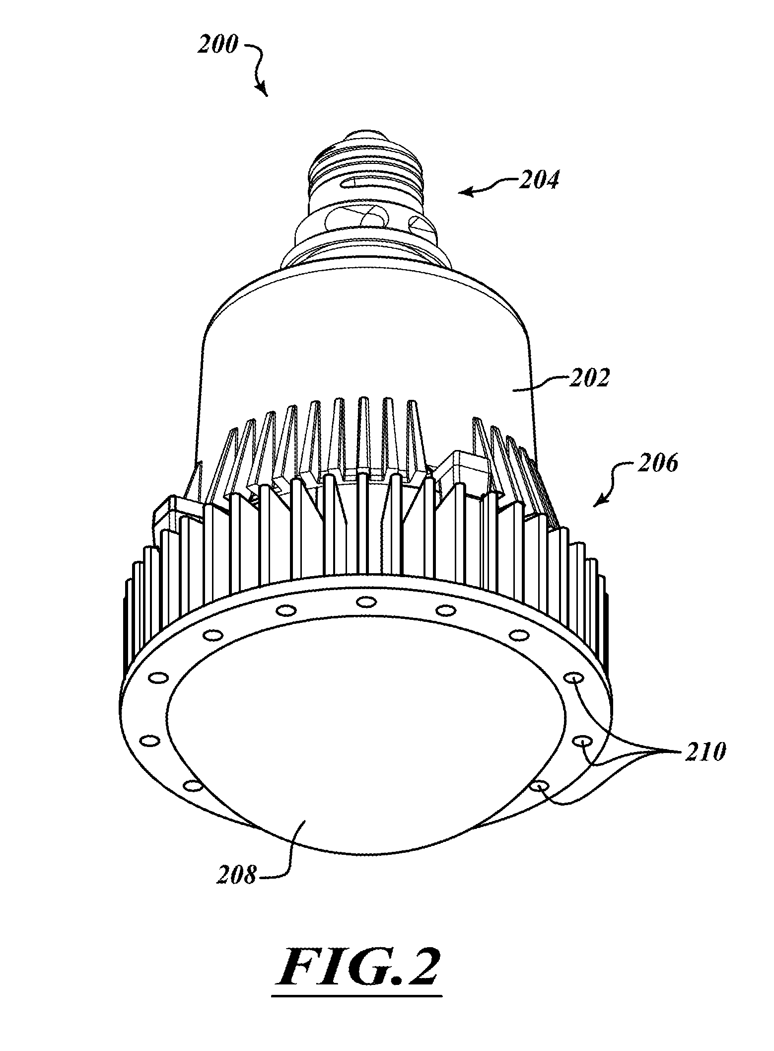
FIG. 2 is an isometric view of a lamp, according to one illustrated embodiment.
FIG. 3 is an isometric view of a lamp, according to another illustrated embodiment.
DETAILED DESCRIPTION
In the following description, certain specific details are set forth in order to provide a thorough understanding of various disclosed embodiments. However, one skilled in the relevant art will recognize that embodiments may be practiced without one or more of these specific details, or with other methods, components, materials, etc. In other instances, well-known structures associated with lighting systems, for example power converters, thermal management structures and subsystems, and/or solid state lights have not been shown or described in detail to avoid unnecessarily obscuring descriptions of the embodiments.
Unless the context requires otherwise, throughout the specification and claims which follow, the word "comprise" and variations thereof, such as, "comprises" and "comprising" are to be construed in an open, inclusive sense, that is as "including, but not limited to."
Reference throughout this specification to "one embodiment" or "an embodiment" means that a particular feature, structure or characteristic described in connection with the embodiment is included in at least one embodiment. Thus, the appearances of the phrases "in one embodiment" or "in an embodiment" in various places throughout this specification are not necessarily all referring to the same embodiment. Furthermore, the particular features, structures, or characteristics may be combined in any suitable manner in one or more embodiments.
As used in this specification and the appended claims, the singular forms "a," "an," and "the" include plural referents unless the content clearly dictates otherwise. It should also be noted that the term "or" is generally employed in its sense including "and/or" unless the content clearly dictates otherwise.
As used in the specification and the appended claims, references are made to a "node" or "nodes." It is understood that a node may be a pad, a pin, a junction, a connector, a wire, or any other point recognizable by one of ordinary skill in the art as being suitable for making an electrical connection within an integrated circuit, on a circuit board, in a chassis or the like.
The headings and Abstract of the Disclosure provided herein are for convenience only and do not interpret the scope or meaning of the embodiments.
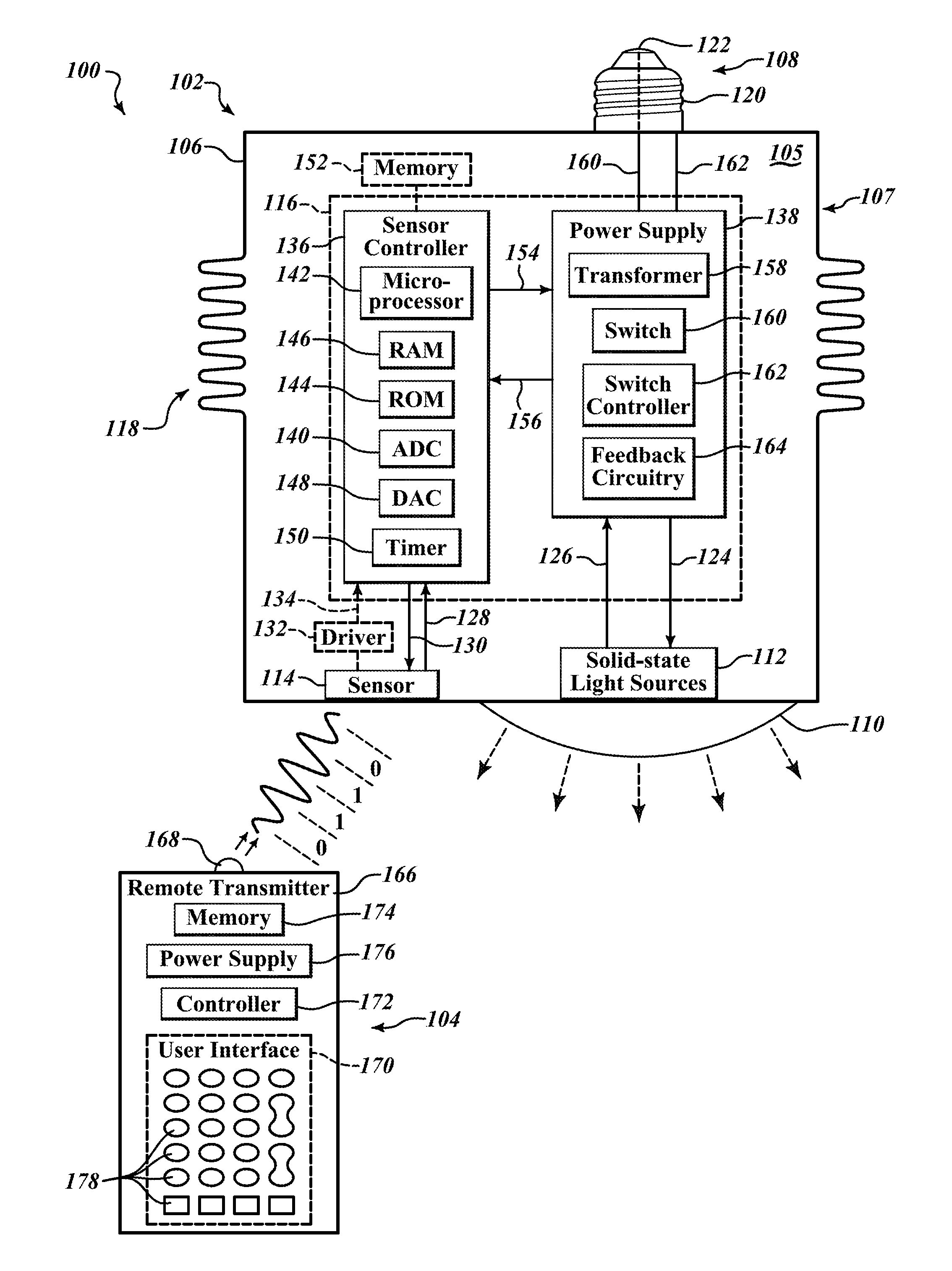
FIG. 1 shows a lighting system 100. The lighting system 100 includes a lamp 102 operable to receive a number of line-of-sight wireless signals from a remote transmitter 104.
The lamp 102 may be used with lighting fixtures having a coupler (e.g., receptacle, for instance an Edison threaded female receptacle) configured to provide detachable physical and electrical connections to the lamp 102. The lamp 102 may include a housing 106, a coupler 108, a lens 110, one or more solid-state light sources 112, a sensor 114, and driver electronics 116. The lamp 102 may take the form of a luminaire, providing a complete lighting unit, including light sources, coupler (e.g., male coupler), housing, wiring, and/or optional reflector(s).
The housing 106 may be configured to provide protection to the driver electronics 116 against environmental elements and to provide a structure for transferring heat from an interior 105 of the housing 106 to an exterior ambient environment that surrounds the housing 106 via thermal radiation and/or convection.
The housing 106 may be manufactured or formed from metal, composites, or the like. If formed from metal, housing 106 may be treated with a rust-resilient coating or chemical. The interior 105 of the housing 106 may be hermetically sealed to prevent rain, wind, moisture, and dust from entering the housing 106. The driver electronics 116 may be positioned within the hermetically sealed interior 105 of the housing 106 to prevent or decrease exposure of the driver electronics 116 to environmental elements that may result in corrosion and a shortened life-span of the driver electronics 116.
Alternatively, the housing 106 may include structures which are configured to decrease or regulate the temperature within the housing 106 as well as the temperature of the housing 106. For example, the housing 106 may include a plurality of openings between an outside of the housing 106 and an inside of the housing 106 to enable passive or active heat transfer from the driver electronics 116. The housing 106 may also include fins 118 that protrude from an outer surface 107 of the housing 106. The fins 118 may increase the surface area of the outer surface 107 of the housing 106 to increase the dissipation of heat from the housing 106 through thermal radiation and/or convection.
The housing 106 may physically carry the driver electronics 116 to transfer heat from the driver electronics via conduction. In particular, the housing 106 may include one or more flat surfaces operable to thermally conduct heat away from the driver electronics 116 while the driver electronics 116 are physically and/or thermally conductively coupled to the one or more flat surfaces. Alternatively, the housing 106 may be adaptable to receive a heat sink in the form of a thermally conductive plate or block to which the driver electronics may be physically and/or thermally conductively coupled. Accordingly, the housing 106 may be configured to dissipate heat from the driver electronics 116 through conduction. The housing 106 may sink heat and emit or transfer the heat to the ambient environment surrounding the outer surface 107, most likely via convection and secondarily via radiant heat transfer. The housing 106 may sink heat from the driver electronics 116 via conduction, convection, and/or radiation.
The coupler 108 may be physically attached to the housing 106 to provide a detachable electrical and physical interface to light fixtures. The coupler 108 includes an outer electrode 120 and an inner electrode 122.
The outer electrode 120 may be configured to physically, electrically, detachably, and complementarily couple or mate with receiving couplers of light fixtures. The outer electrode 120 may be manufactured from an electrically conductive material, such as aluminum, tin, copper, or the like. The outer electrode 120 may be formed to include threads, such as may be found on a cap of a traditional light bulb (e.g., Edison screw base). Accordingly, the coupler 108 may be rotatably coupled to complementarily receiving couplers of light fixtures based on the shape of the outer electrode 120.
The outer electrode 120 may be electrically connected to the driver electronics 116 to provide power to the one or more solid-state light sources 112. The outer electrode 120 may be electrically coupled to a complementary electrode of a light fixture to receive power and to supply the received power to the driver electronics 116. Alternatively, the outer electrode 120 may be electrically coupled to a complementary electrode of a light fixture that provides a ground reference. Electrically coupling the outer electrode 122 to the ground reference may provide a return path to the ground reference for current flowing through the driver electronics 116. The outer electrode 120 may also be electrically coupled to the housing 106 to provide a path to the ground reference that reduces build-up of electrical charge on the housing 106.
The inner electrode 122 is electrically insulated from the outer electrode 120 and may be configured to physically, electrically, detachably, and complementarily couple or mate with receiving couplers of light fixtures. The inner electrode 122 may coupled to a complementary electrode in a light fixture to receive power from a light fixture. The inner electrode 122 may be electrically connected to the driver electronics 116 via wires or electrically conductive traces and may transfer power from the light fixture to the driver electronics 116.
The lens 110 is positioned over an opening in the housing 106 and is physically coupled to the housing 106 to at least partially enclose the solid-state light sources 112. The lens 110 may be made from plastic, glass, or the like and is transmissive over at least a portion of the visible light spectrum. The lens 110 may have a nadir surface with a shape that is convex, concave, or approximately flat. Additionally, the lens 110 may include or form a color filter that is operable to adjust the color temperature of light emitted from the solid-state light sources 112. The lens 110 may detachably couple to the housing 106 so that lenses having different shapes and transmission characteristics may be interchangeably coupled to the housing 106.
The solid-state light sources 112 are carried by the housing 106 and are positioned relatively behind the lens with respect to a direction in which light is transmitted by the solid-state light sources 112. The solid-state light sources 112 may include one or more light emitting diodes (LEDs). The LEDs may be one of any of a variety of LEDs, such as phosphor-based LEDs, organic LEDs (OLEDs), or the like. The LEDs may be electrically coupled together in series, in parallel, or in a combination of electrical series and parallel to form a string of LEDs. The solid-state light sources 112 may also receive power from the driver electronics 116 through an electrically conductive path 124 and provide feedback to the driver electronics 116 through an electrically conductive return path 126.
The at least one sensor 114 may be positioned within the housing 106 to receive a number of line-of-sight wireless signals through the lens 110. The at least one sensor 114 may take the form of a photodiode, a CMOS image sensor, or another passive or active photosensitive device. The at least one sensor 114 may transmit output signals to the driver electronics 116 via a communication path 128. The at least one sensor 114 may optionally receive instructions or commands from the driver electronics 116 via a communication path 130. The at least one sensor 114 may be attached to a substrate or backplane that is at least partially enclosed by the lens 110 and the housing 106. The at least one sensor 114 is positioned within the housing 106 so as to be at least partially communicatively line-of-sight accessible through the lens 110. The at least one sensor 114 may be spatially distributed relatively behind the lens 110 to receive the number of line-of-sight wireless signals from a variety of angles of incidence. Alternatively, the at least one sensor 114 may be received or recessed in the housing 106, for example, around a perimeter of the lens 110, or otherwise physically coupled thereto.
The at least one sensor 114 provides a number of wireless sensor output signals that are representative of the sensed line-of-sight wireless signals to the driver electronics 116. The number of line-of-sight wireless signals may be transmitted from the remote transmitter 104 with one of a variety of modulation techniques. For example, the remote transmitter 104 may transmit a number of line-of-sight wireless signals using amplitude modulation, frequency modulation, pulse-code modulation, or the like. The number of line-of-sight wireless signals may also be transmitted in a variety of speeds such as serial infrared (SIR), medium infrared (MIR), fast infrared (FIR), or the like, as defined by the Infrared Data Association (IrDA).
The at least one sensor 114 converts the received number of line-of-sight wireless signals into output signals that are electrical representatives of the wireless signals. The at least one sensor 114 may then transmit the output signals to the driver electronics 116 via the communication path 128. The at least one sensor 114 may convert the optically received wireless signals into voltage and/or current signals having a frequency and amplitude that is proportional to the number of line-of-sight wireless signals. For example, the number of line-of-sight wireless signals may carry or encode a security code comprising a particular sequence of ones and zeros that are amplitude modulated and transmitted by the remote transmitter 104. The at least one sensor 114 may correspondingly convert the amplitude modulated and optically transmitted line-of-sight wireless signals into output signals (e.g., optical, voltage, current, or the like) that are representative of the sequence of ones and zeros that constitute the security code or other data carried by the wireless signals.
A sensor output driver 132 may function as a repeater that optionally receives the output signals from the at least one sensor 114 and transmits the output signals to the driver electronics 116. The output signals from the at least one sensor 114 may represent line-of-sight wireless signals that have been weakly transmitted or transmitted at the cusp of the range of detection of the at least one sensor 114. The sensor output driver 132 may thus amplify the output signals to improve reception of the output signals by the driver electronics 116. Additionally, the at least one sensor 114 may be a plurality of sensors that simultaneously receive or sense the number of line-of-sight wireless signals, and the sensor output driver 132 may sum or mix the combination of output signals from the plurality of sensors 114 prior to transmitting the combination of output signals to the driver electronics 116 for demodulation. In particular, the sensor output driver 132 may transmit the output signals to the driver electronics 116 via a communication path 134.
The driver electronics 116 may be electrically coupled between the coupler 108 and the solid-state light sources 112 to adjust an amount of light output by the solid-state light sources. The driver electronics 116 may adjust the amount of light output by the solid-state light sources based at least in part on the line-of-sight wireless signals sensed by the at least one sensor 114. The driver electronics 116 may include a sensor controller 136 and a power supply 138.
The sensor controller 136 is configured to adjust one or more inputs of the power supply 138 in response to the output signals received from the at least one sensor 114. The sensor controller 136 may include an analog-to-digital converter (ADC) 140, a processor 142, a read-only memory (ROM) 144, a random-access memory 146, and a digital-to-analog converter (DAC) 148. The sensor controller 136 optionally includes one or more timers 150.
The ADC 140 may be coupled to the communication paths 128 and/or 134 to receive the output signals from the at least one sensor 114 and/or the sensor driver 132. The ADC 140 may be allocated one or more input terminals of the sensor controller 136 by which to receive the output signals from the communication paths 128, 134. The ADC 140 converts the output signals to a digital format having one or more bits for use by the processor 142. The ADC 140 may convert the output signals to a single-bit digital sequence based on a frequency of an oscillator.
The processor 142 determines whether instructions or other information is carried by the number of line-of-sight wireless signals, such as an access identifier or light intensity adjustment instructions. The processor 142 may be communicatively coupled to receive the digitized output signals, i.e., sensor data, from the ADC 140. The processor 142 may be configured to temporarily store the sensor data in the RAM 146 in response to instructions stored in the ROM 144. The processor 142 may then determine whether instructions or other information is carried by the sensor data by comparing the stored sensor data to instructions, access identifiers, or the like that are stored in the RAM 146. Alternatively, the processor 142 may store the sensor data in a memory 152 that is external to the sensor controller 136.
The memory 152 may be readable and writable and be communicatively coupled to the sensor controller 136. The memory 152 may be a non-volatile memory such as flash. The memory 152 may be programmed during a manufacture process of the lamp 102 to include manufacturer-established access identifiers and adjustment instructions, as well as default settings for other user-customizable features.
The processor 142 may validate an access identifier carried by the sensor data, such as the pass code or security code. The processor 142 may compare the sensor data against authorization or identification data, such as one or more master access identifiers, stored in the ROM 144, RAM 146, or the memory 152. The master access identifier may be programmed into the ROM 144 or the memory 152 by the manufacturer or may be programmed into the memory 152 by a user. The processor 142 may be configured to ignore any other instructions carried by the sensor data until the access identifier matches data, such as the one or more master access identifiers, stored in at least one of the memories 144, 146, and 152.
The processor 142 may validate light intensity adjustment instructions. In response to validating the access identifier, the processor 142 may cause the sensor controller 136 to enter a command mode. In the command mode, the sensor controller 136 may become responsive to adjustment instructions to vary the light intensity of the solid-state light sources 112. Specifically, in the command mode the processor 142 may compare the sensor data to adjustment instructions stored in the ROM 144. Validation occurs when the processor 142 determines that sensor data matches an adjustment instruction, after which the processor 142 communicates the adjustment instruction to the power supply 138. Additionally, the processor 142 may be configured to ignore adjustment instructions carried by the sensor data until the command mode has been entered.
The sensor controller 136 may stay in the command mode for a duration determined by the timer 150. In response to entering the command mode, the processor 142 may execute the timer 150 and exit the command mode at the expiration of the timer 150. The processor 142 may additionally reinitiate the timer 150 upon receipt of each validated light intensity adjustment instruction. In this way, a user may continue to increase and decrease the light intensity of the solid-state light sources 112 without having to retransmit the access identifier.
The processor 142 may communicate adjustment instructions from the sensor controller 136 to the power supply 138 in several ways. The sensor controller 136 may be communicatively coupled to the power supply 138 via a communication path 154. The processor 142 may transmit or adjust an analog voltage on the communication path 154, for example by altering an output of the DAC 148. The processor 142 may cause the DAC 148 to output an increased or decreased voltage to the communication path 154 in response to adjustment instructions to increase the light intensity or decrease the light intensity, respectively. Alternatively, the processor 142 may transmit light intensity adjustment instructions to the power supply 138 via the communication path 154 in the form of one or more digital bytes. The sensor controller 136 may receive acknowledgment from the power supply 138 via a connection 156 in response to the communicated adjustment instructions. Alternatively, the sensor controller 136 may use the connection 156 to receive power from the power supply 138.
Accordingly, the driver electronics 116 are responsive to adjustment instructions to vary the amount of light output by the solid-state light sources 112.
When the lamp 102 is initially powered ON, the processor 142 may retrieve an initial light intensity setting for the solid-state light sources 112. The processor 142 may retrieve the setting from the memory 152. The processor may then cause the DAC 148 to output a level of voltage corresponding to the light intensity setting onto the communication path 154 to set the output intensity of the solid-state light sources 112. When the lamp 102 receives a valid instruction to adjust the light intensity for the solid-state light sources 112, the processor 142 may store a setting corresponding to the new light intensity in the memory 152. The new light intensity setting stored in the memory 152 may then be used the next time the lamp 102 is switched OFF and ON again.
The power supply 138 is electrically coupled between the coupler 108, the solid-state light sources 112, and the sensor controller 136 to selectively vary the output intensity of the solid-state light sources 112. The power supply 138 may vary the output intensity of the solid-state light sources 112 by varying the duty cycle of the power signal to the solid-state light sources 112, by selectively choosing between different numbers of solid-state light sources 112 (e.g., 15 LEDs at one time and 30 LEDs at another), or by varying the magnitude of current and/or voltage to the solid-state light sources 112. The power supply 138 may receive power from the coupler 108 via a voltage reference line 155 and a ground reference line 157. The power supply 138 may include a transformer 158, a switch 160, a switch controller 162, and feedback circuitry 164.
The transformer 158 may be electrically coupled to receive power from the voltage reference line 155 and the ground reference line 157. The transformer 158 may be configured to increase or decrease the voltage received from the voltage reference line 155. The transformer 158 may be electrically coupled to conductive path 124 to provide power to the solid-state light sources 112. The transformer 158 may provide more or less power to the solid-state light sources 112 based upon the duration and/or frequency with which current is permitted to flow through at least one winding of the transformer 158.
The switch 160 may be electrically coupled between the ground reference line 157 and the transformer 158 to selectively conduct current through the at least one winding of the transformer 158. The switch 160 may be a metal oxide semiconductor field effect transistor (MOSFET), an insulated gate bipolar transistor (IGBT), or the like. The switch 160 may include a control terminal that is electrically coupled to be operated from the switch controller 162.
The switch controller 162 may be configured to control the duration and frequency with which current flows through the at least one winding of the transformer 158 by selectively operating the switch 160. The switch controller 162 may operate the switch 160 by transmitting a series of pulses to the control terminal of the switch 160. The switch controller 162 may vary the amplitude, duty cycle, and/or frequency of the series of pulses in response to the input received from the sensor controller 136.
The switch controller 162 may have an input that is electrically coupled to the communication path 154. The switch controller 162 may sense a voltage level on the communication path 154. The switch controller 162 may increase the power output to the solid-state light sources 112 and decrease the power output to the solid-state light sources 112 in response to respective increases and decreases in the level of voltage on the communication path 154. Specifically, the switch controller 162 may increase or decrease the duty cycle and/or frequency of the series of pulses transmitted to the switch 160 to increase or decrease, respectively, the power output by the transformer 158.
The feedback circuitry 164 may provide information to the switch controller 162 that is indicative of an amount of power being supplied to the solid-state light sources 112. The feedback circuitry 164 may be electrically coupled to the conductive return path 126 to monitor the current flowing through the solid-state light sources 112. The feedback circuitry 164 may be electrically coupled to the communication path 154 and may be responsive to the level of voltage on the communication path 154. In other words, the feedback circuitry 164 may increase or decrease the light intensity of the solid-state light sources 112 by adjusting the feedback provided to the switch controller 162 based on the level of voltage on the communication path 154.
The remote transmitter 104 transmits the number of line-of-sight wireless signals to the lamp 102 to adjust the output intensity of the solid-state light sources 112. The remote transmitter 104 may include a remote transmitter housing 166, an optical transmission device 168, a user interface 170, a remote transmitter controller 172, a memory 174, and a power supply 176.
The optical transmission device 168 transmits the number of line-of-sight wireless signals in response to commands from the remote transmitter 104. Optical transmission device 168 may be operable to transmit the wireless signals in any one of a variety of formats, such as amplitude modulation, frequency modulation, or pulse code modulation. The optical transmission device 168 may be a photodiode carried by the remote transmitter housing 166 and configured to transmit light within the infrared frequency band. The optical transmission device 168 transmits the wireless signals based upon inputs provided to the user interface 170.
The user interface 170 may take one of a variety of forms. For example, the user interface 170 may include a plurality of buttons or keys 178. The user interface 170 may enable a user to enter a series of numbers representing the access identifier, for example, 3-1-5-5-5-2. As discussed above, the access identifier may be programmed into a memory 144, 152 in the lamp 102 by the manufacturer and may be reprogrammed to a desired value by the user. Alternatively, the user interface 170 may be a touchscreen interface, such as a resistive touchscreen, a passive touchscreen, or an acoustic touchscreen with a graphical user interface including one or more user selectable icons. As another alternative, the user interface 170 may include a microphone and be configured to receive audio commands from the user.
The remote transmitter controller 172 may be electrically coupled between the user interface 170 and the optical transmission device 168. The remote transmitter controller 172 translates commands that are manually or vocally entered via the user interface 170 into digital signals for optical transmission. The controller 172 may translate commands entered into the user interface 170 in response to an instruction set stored in the memory 174.
The memory 174 may be a volatile or nonvolatile memory. The memory 174 may store instructions for running the controller 172. Additionally, the memory 174 may store shortcuts or defined settings or other user preferences programmed by a user through the user interface 170.
The power supply 176 may supply current voltage to remote transmitter 104. The power supply 176 may be electrically connected to optical transmission device 168, the controller 172, and the memory 174. The power supply 176 may be a replaceable battery. The battery may be a lithium-ion battery, a nickel metal hydride battery, or the like. Alternatively, or additionally the power supply may include a photovoltaic cell that provides charge to a charge storage device, such as a capacitor.
In operation, the lighting system 100 may be operated in the following hypothetical manner. A user may walk onto a floor of a store which has installed one or more lamps 102 overhead. The user may determine that the output intensity of one or more of the lamps 102 is too bright. The user may point the remote transmitter 104 in the direction of the sensor 114 from beneath a selected lamp 102 and enter the access identifier, such as 3-1-5-5-5-2. In response to validation of the access identifier, that sensor controller 136 of the driver electronics 116 may enter a command mode. The user may then press a button or key (e.g., labeled "+") of the user interface 170. The remote transmitter 104 may transmit a number of line-of-sight wireless signals corresponding to increasing the light output intensity. The sensor controller 136 may receive the command from the sensor 114 and increase a level of voltage on the communication path 154. In response to the increase in the level of voltage on the communication path 154, the power supply 138 may change the number of solid-state light sources 112 activated, may change the duty cycle of the power supplied to the solid-state light sources 112, or may increase the voltage and/or current supplied through the conductive path 124 to the solid-state light sources 112. As result, the solid-state light sources 112 may emit an increased amount of light. After a predetermined amount of time, (e.g., 5 seconds) the sensor controller 136 may exit command mode, causing the lamp 102 to ignore subsequently received commands from the remote transmitter 104 until the access identifier is again validated.
FIG. 2 illustrates a lamp 200 that may be an implementation of the lamp 102 of the lighting system 100. The lamp 200 may include a housing 202, a physical and electrical coupler 204, a plurality of fins 206, a lens 208 and a plurality of photosensitive sensors 210. As illustrated, the plurality of photosensitive sensors 210 may be received by the housing 202 to surround a perimeter of the lens 208.
FIG. 3 illustrates a lamp 300 that may be an implementation of the lamp 102 of the lighting system 100. The lamp 300 may include a housing 302, an electrical and physical coupler 304, a plurality of fins 306, a lens 308, and a plurality of photosensitive sensors 310. As illustrated, the plurality of photosensitive sensors 310 may be positioned relatively behind the lens 308 and may be enclosed by the housing 302 and the lens 308.
The specific values, such as voltages, used herein are purely illustrative, and are not meant to be in anyway limiting on the scope. Likewise, the arrangements and topologies are merely illustrative and other arrangements and topologies may be employed where consistent with the teachings herein. While specific circuit structures are disclosed, other arrangements that achieve similar functionality may be employed.
The methods illustrated and described herein may include additional acts and/or may omit some acts. The methods illustrated and described herein may perform the acts in a different order. Some of the acts may be performed sequentially, while some acts may be performed concurrently with other acts. Some acts may be merged into a single act through the use of appropriate circuitry. For example, compensation and level shifting may be combined.
To the extent that they are not inconsistent with the teachings herein, the teachings of: U.S. provisional patent application Ser. No. 61/052,924 filed May 13, 2008; U.S. patent application Ser. No. 12/437,467 filed May 7, 2009 and published as U.S. patent application Publication No. 2009-0284155; U.S. provisional patent application Ser. No. 61/051,619 filed May 8, 2008; U.S. patent application Ser. No. 12/437,472 filed May 7, 2009 and published as U.S. patent application Publication No. 2009-0278474; U.S. provisional patent application Ser. No. 61/088,651 filed Aug. 13, 2008; U.S. patent application Ser. No. 12/540,250 filed Aug. 12, 2009 and published as U.S. patent application Publication No. 2010-0090577; U.S. provisional patent application Ser. No. 61/115,438 filed Nov. 17, 2008; U.S. provisional patent application Ser. No. 61/154,619 filed Feb. 23, 2009; U.S. patent application Ser. No. 12/619,535 filed Nov. 16, 2008 and published as U.S. patent application Publication No. 2010-0123403; U.S. provisional patent application Ser. No. 61/174,913 filed May 1, 2009(.406P1); U.S. patent application Ser. No. 12/769,956 filed Apr. 29, 2010 and published as U.S. patent application Publication No. 2010-0277082; U.S. provisional patent application Ser. No. 61/180,017 filed May 20, 2009, U.S. patent application Ser. No. 12/784,080 filed May 2010 and published as U.S. patent application Publication No. 2010-0295946; U.S. provisional patent application Ser. No. 61/229,435 filed Jul. 29, 2009; U.S. patent application Ser. No. 12/846,516 filed Jul. 29, 2010 and published as U.S. patent application Publication No. 2011-0026264; U.S. provisional patent application Ser. No. 61/295,519 filed Jan. 15, 2010; U.S. provisional patent application Ser. No. 61/406,490 filed Oct. 25, 2010; U.S. patent application Ser. No. 13/007,080 filed Jan. 14, 2011; U.S. provisional patent application Ser. No. 61/333,983 filed May 12, 2010; U.S. patent application Ser. No. 12/784,091 filed May 20, 2010 and published as U.S. patent application Publication No. 2011-0295454; U.S. provisional patent application Ser. No. 61/346,263 filed May 19, 2010; U.S. patent application Ser. No. 12/784,093 filed May 20, 2010; U.S. patent application Ser. No. 13/166,626 filed Jun. 22, 2011; U.S. patent application Ser. No. 13/085,301 filed Apr. 12, 2011; U.S. patent application Ser. No. 13/212,074 filed Aug. 17, 2011; and U.S. provisional patent application Ser. No. 61/534,722 filed Sep. 14, 2011 are each incorporated herein by reference in their entirety.
The various embodiments described above can be combined to provide further embodiments. Aspects of the embodiments can be modified, if necessary to employ concepts of the various patents, applications and publications to provide yet further embodiments.
These and other changes can be made to the embodiments in light of the above-detailed description. In general, in the following claims, the terms used should not be construed to limit the claims to the specific embodiments disclosed in the specification and the claims, but should be construed to include all possible embodiments along with the full scope of equivalents to which such claims are entitled. Accordingly, the claims are not limited by the disclosure.
* * * * *
References
D00000
D00001
D00002
D00003
XML
uspto.report is an independent third-party trademark research tool that is not affiliated, endorsed, or sponsored by the United States Patent and Trademark Office (USPTO) or any other governmental organization. The information provided by uspto.report is based on publicly available data at the time of writing and is intended for informational purposes only.
While we strive to provide accurate and up-to-date information, we do not guarantee the accuracy, completeness, reliability, or suitability of the information displayed on this site. The use of this site is at your own risk. Any reliance you place on such information is therefore strictly at your own risk.
All official trademark data, including owner information, should be verified by visiting the official USPTO website at www.uspto.gov. This site is not intended to replace professional legal advice and should not be used as a substitute for consulting with a legal professional who is knowledgeable about trademark law.