Energy delivery devices and methods
Danek , et al. December 30, 2
U.S. patent number 8,920,413 [Application Number 11/420,407] was granted by the patent office on 2014-12-30 for energy delivery devices and methods. This patent grant is currently assigned to Asthmatx, Inc.. The grantee listed for this patent is Christopher J. Danek, Gary S. Kaplan, Michael D. Laufer, William J. Wizeman. Invention is credited to Christopher J. Danek, Gary S. Kaplan, Michael D. Laufer, William J. Wizeman.


View All Diagrams
| United States Patent | 8,920,413 |
| Danek , et al. | December 30, 2014 |
Energy delivery devices and methods
Abstract
This relates to methods and devices for improving treatment to a wall, a cavity or passageway with a medical device when used in tortuous anatomy.
| Inventors: | Danek; Christopher J. (San Carlos, CA), Kaplan; Gary S. (San Francisco, CA), Wizeman; William J. (Mountain View, CA), Laufer; Michael D. (Menlo Park, CA) | ||||||||||
|---|---|---|---|---|---|---|---|---|---|---|---|
| Applicant: |
|
||||||||||
| Assignee: | Asthmatx, Inc. (Sunnyvale,
CA) |
||||||||||
| Family ID: | 37986249 | ||||||||||
| Appl. No.: | 11/420,407 | ||||||||||
| Filed: | May 25, 2006 |
Prior Publication Data
| Document Identifier | Publication Date | |
|---|---|---|
| US 20060247617 A1 | Nov 2, 2006 | |
Related U.S. Patent Documents
| Application Number | Filing Date | Patent Number | Issue Date | ||
|---|---|---|---|---|---|
| PCT/US2005/041243 | Nov 14, 2005 | ||||
| 11255796 | Oct 21, 2005 | ||||
| 60627662 | Nov 12, 2004 | ||||
| Current U.S. Class: | 606/41 |
| Current CPC Class: | A61B 90/30 (20160201); A61B 18/1492 (20130101); A61B 2018/00791 (20130101); A61B 2018/0022 (20130101); A61N 7/022 (20130101); A61B 18/08 (20130101); A61B 2018/00821 (20130101); A61B 2018/00541 (20130101); A61B 2018/00214 (20130101); A61B 2018/00267 (20130101); A61B 2018/00797 (20130101); A61B 18/02 (20130101) |
| Current International Class: | A61B 18/14 (20060101); A61B 18/18 (20060101); A61N 7/02 (20060101) |
| Field of Search: | ;606/32-50 |
References Cited [Referenced By]
U.S. Patent Documents
| 1155169 | September 1915 | Starkweather |
| 1207479 | December 1916 | Bisgaard |
| 2072346 | March 1937 | Smith |
| 3320957 | May 1967 | Sokolik |
| 3568659 | March 1971 | Karnegis |
| 3667476 | June 1972 | Muller |
| 3692029 | September 1972 | Adair |
| 4461283 | July 1984 | Doi |
| 4503855 | March 1985 | Maslanka |
| 4522212 | June 1985 | Gelinas et al. |
| 4565200 | January 1986 | Cosman |
| 4567882 | February 1986 | Heller |
| 4584998 | April 1986 | McGrail |
| 4612934 | September 1986 | Borkan |
| 4643186 | February 1987 | Rosen et al. |
| 4674497 | June 1987 | Ogasawara |
| 4706688 | November 1987 | Don Michael et al. |
| 4709698 | December 1987 | Johnston et al. |
| 4754752 | July 1988 | Ginsburg et al. |
| 4799479 | January 1989 | Spears |
| 4802492 | February 1989 | Grunstein |
| 4825871 | May 1989 | Cansell |
| 4827935 | May 1989 | Geddes et al. |
| 4862886 | September 1989 | Clarke et al. |
| 4920978 | May 1990 | Colvin |
| 4955377 | September 1990 | Lennox et al. |
| 4967765 | November 1990 | Turner et al. |
| 4976709 | December 1990 | Sand |
| 5010892 | April 1991 | Colvin et al. |
| 5019075 | May 1991 | Spears et al. |
| 5053033 | October 1991 | Clarke |
| 5056519 | October 1991 | Vince |
| 5074860 | December 1991 | Gregory et al. |
| 5078716 | January 1992 | Doll |
| 5084044 | January 1992 | Quint |
| 5096916 | March 1992 | Skupin |
| 5100388 | March 1992 | Behl et al. |
| 5100423 | March 1992 | Fearnot |
| 5103804 | April 1992 | Abele et al. |
| 5106360 | April 1992 | Ishiwara et al. |
| 5116864 | May 1992 | March et al. |
| 5117828 | June 1992 | Metzger et al. |
| 5135517 | August 1992 | McCoy |
| 5152286 | October 1992 | Sitko et al. |
| 5170803 | December 1992 | Hewson et al. |
| 5174288 | December 1992 | Bardy et al. |
| 5188602 | February 1993 | Nichols |
| 5191883 | March 1993 | Lennox et al. |
| 5215103 | June 1993 | Desai |
| 5254088 | October 1993 | Lundquist et al. |
| 5255678 | October 1993 | Deslauriers et al. |
| 5255679 | October 1993 | Imran |
| 5265604 | November 1993 | Vince |
| 5269758 | December 1993 | Taheri |
| 5281218 | January 1994 | Imran |
| 5292331 | March 1994 | Boneau |
| 5293869 | March 1994 | Edwards et al. |
| 5309910 | May 1994 | Edwards et al. |
| 5311866 | May 1994 | Kagan et al. |
| 5313943 | May 1994 | Houser et al. |
| 5324284 | June 1994 | Imran |
| 5343936 | September 1994 | Beatenbough et al. |
| 5345936 | September 1994 | Pomeranz et al. |
| 5366443 | November 1994 | Eggers et al. |
| 5368591 | November 1994 | Lennox et al. |
| 5370644 | December 1994 | Langberg |
| 5370679 | December 1994 | Atlee, III |
| 5374287 | December 1994 | Rubin |
| 5383917 | January 1995 | Desai et al. |
| 5394880 | March 1995 | Atlee, III |
| 5396887 | March 1995 | Imran |
| 5400783 | March 1995 | Pomeranz et al. |
| 5411025 | May 1995 | Webster, Jr. |
| 5415166 | May 1995 | Imran |
| 5415656 | May 1995 | Tihon et al. |
| 5417687 | May 1995 | Nardella et al. |
| 5423744 | June 1995 | Gencheff et al. |
| 5423811 | June 1995 | Imran et al. |
| 5425703 | June 1995 | Feiring |
| 5431696 | July 1995 | Atlee, III |
| 5433730 | July 1995 | Alt |
| 5443470 | August 1995 | Stern et al. |
| 5454782 | October 1995 | Perkins |
| 5456667 | October 1995 | Ham et al. |
| 5458596 | October 1995 | Lax et al. |
| 5465717 | November 1995 | Imran et al. |
| 5471982 | December 1995 | Edwards et al. |
| 5474530 | December 1995 | Passafaro et al. |
| 5478309 | December 1995 | Sweezer et al. |
| 5496271 | March 1996 | Burton et al. |
| 5496311 | March 1996 | Abele et al. |
| 5500011 | March 1996 | Desai |
| 5505728 | April 1996 | Ellman et al. |
| 5505730 | April 1996 | Edwards |
| 5509419 | April 1996 | Edwards et al. |
| 5522862 | June 1996 | Testerman et al. |
| 5531779 | July 1996 | Dahl et al. |
| 5540681 | July 1996 | Strul et al. |
| 5545161 | August 1996 | Imran |
| 5545193 | August 1996 | Fleischman et al. |
| 5547469 | August 1996 | Rowland et al. |
| 5549559 | August 1996 | Eshel |
| 5549655 | August 1996 | Erickson |
| 5549661 | August 1996 | Kordis et al. |
| RE35330 | September 1996 | Malone et al. |
| 5558073 | September 1996 | Pomeranz et al. |
| 5562608 | October 1996 | Sekins et al. |
| 5571088 | November 1996 | Lennox et al. |
| 5582609 | December 1996 | Swanson et al. |
| 5588432 | December 1996 | Crowley |
| 5595183 | January 1997 | Swanson et al. |
| 5598848 | February 1997 | Swanson et al. |
| 5599345 | February 1997 | Edwards et al. |
| 5601088 | February 1997 | Swanson et al. |
| 5605157 | February 1997 | Panescu et al. |
| 5607419 | March 1997 | Amplatz et al. |
| 5607462 | March 1997 | Imran |
| 5620438 | April 1997 | Amplatz et al. |
| 5623940 | April 1997 | Daikuzono |
| 5624439 | April 1997 | Edwards et al. |
| 5626618 | May 1997 | Ward et al. |
| 5630425 | May 1997 | Panescu et al. |
| 5630794 | May 1997 | Lax et al. |
| 5632767 | May 1997 | Sinofsky |
| 5634471 | June 1997 | Fairfax et al. |
| 5647870 | July 1997 | Kordis et al. |
| 5678535 | October 1997 | DiMarco |
| 5680860 | October 1997 | Imran |
| 5681280 | October 1997 | Rusk et al. |
| 5681308 | October 1997 | Edwards et al. |
| 5693078 | December 1997 | Desai et al. |
| 5695482 | December 1997 | Kaldany |
| 5699799 | December 1997 | Xu et al. |
| 5707352 | January 1998 | Sekins et al. |
| 5722401 | March 1998 | Pietroski et al. |
| 5722403 | March 1998 | McGee et al. |
| 5722416 | March 1998 | Swanson et al. |
| 5725525 | March 1998 | Kordis |
| 5728094 | March 1998 | Edwards |
| 5730128 | March 1998 | Pomeranz et al. |
| 5730726 | March 1998 | Klingenstein |
| 5730741 | March 1998 | Horzewski et al. |
| 5740808 | April 1998 | Panescu et al. |
| 5752518 | May 1998 | McGee et al. |
| 5755753 | May 1998 | Knowlton |
| 5759158 | June 1998 | Swanson |
| 5762631 | June 1998 | Klein |
| 5769846 | June 1998 | Edwards et al. |
| 5772590 | June 1998 | Webster, Jr. |
| 5779669 | July 1998 | Haissaguerre et al. |
| 5779698 | July 1998 | Clayman et al. |
| 5782239 | July 1998 | Webster, Jr. |
| 5782827 | July 1998 | Gough et al. |
| 5782899 | July 1998 | Imran |
| 5792064 | August 1998 | Panescu et al. |
| 5795303 | August 1998 | Swanson et al. |
| 5807306 | September 1998 | Shapland et al. |
| 5810807 | September 1998 | Ganz et al. |
| 5823189 | October 1998 | Kordis |
| 5827277 | October 1998 | Edwards |
| 5836947 | November 1998 | Fleischman et al. |
| 5837001 | November 1998 | Mackey |
| 5843075 | December 1998 | Taylor |
| 5843077 | December 1998 | Edwards |
| 5846238 | December 1998 | Jackson et al. |
| 5848969 | December 1998 | Panescu et al. |
| 5848972 | December 1998 | Triedman et al. |
| 5855577 | January 1999 | Murphy-Chutorian et al. |
| 5860974 | January 1999 | Abele |
| 5863291 | January 1999 | Schaer |
| 5865791 | February 1999 | Whayne et al. |
| 5868740 | February 1999 | LeVeen et al. |
| 5871443 | February 1999 | Edwards et al. |
| 5871523 | February 1999 | Fleischman et al. |
| 5873865 | February 1999 | Horzewski et al. |
| 5876340 | March 1999 | Tu et al. |
| 5876399 | March 1999 | Chia et al. |
| 5881727 | March 1999 | Edwards |
| 5882346 | March 1999 | Pomeranz et al. |
| 5891135 | April 1999 | Jackson et al. |
| 5891136 | April 1999 | McGee et al. |
| 5891138 | April 1999 | Tu et al. |
| 5893847 | April 1999 | Kordis |
| 5897554 | April 1999 | Chia et al. |
| 5899882 | May 1999 | Waksman et al. |
| 5904651 | May 1999 | Swanson et al. |
| 5904711 | May 1999 | Flom et al. |
| 5906636 | May 1999 | Casscells, III et al. |
| 5908445 | June 1999 | Whayne et al. |
| 5908446 | June 1999 | Imran |
| 5911218 | June 1999 | DiMarco |
| 5916235 | June 1999 | Guglielmi |
| 5919147 | July 1999 | Jain |
| 5928228 | July 1999 | Kordis et al. |
| 5935079 | August 1999 | Swanson et al. |
| 5941869 | August 1999 | Patterson et al. |
| 5951494 | September 1999 | Wang et al. |
| 5954661 | September 1999 | Greenspon et al. |
| 5954662 | September 1999 | Swanson et al. |
| 5954717 | September 1999 | Behl et al. |
| 5957961 | September 1999 | Maguire et al. |
| 5964753 | October 1999 | Edwards |
| 5964796 | October 1999 | Imran |
| 5971983 | October 1999 | Lesh |
| 5972026 | October 1999 | Laufer et al. |
| 5979456 | November 1999 | Magovern |
| 5980563 | November 1999 | Tu et al. |
| 5991650 | November 1999 | Swanson et al. |
| 5992419 | November 1999 | Sterzer et al. |
| 5993382 | November 1999 | Pruitt, Sr. |
| 5993462 | November 1999 | Pomeranz et al. |
| 5997534 | December 1999 | Tu et al. |
| 5997571 | December 1999 | Farr et al. |
| 5999855 | December 1999 | DiMarco |
| 6003517 | December 1999 | Sheffield et al. |
| 6004269 | December 1999 | Crowley et al. |
| 6006755 | December 1999 | Edwards |
| 6009877 | January 2000 | Edwards |
| 6010500 | January 2000 | Sherman et al. |
| 6014579 | January 2000 | Pomeranz et al. |
| 6016437 | January 2000 | Tu et al. |
| 6023638 | February 2000 | Swanson |
| 6024740 | February 2000 | Lesh et al. |
| 6029091 | February 2000 | De la Rama et al. |
| 6033397 | March 2000 | Laufer et al. |
| 6036687 | March 2000 | Laufer et al. |
| 6036689 | March 2000 | Tu et al. |
| 6039731 | March 2000 | Taylor et al. |
| 6045549 | April 2000 | Smethers et al. |
| 6045550 | April 2000 | Simpson et al. |
| 6050992 | April 2000 | Nichols |
| 6053172 | April 2000 | Hovda et al. |
| 6056744 | May 2000 | Edwards |
| 6069698 | May 2000 | Ozawa et al. |
| 6071279 | June 2000 | Whayne et al. |
| 6071280 | June 2000 | Edwards et al. |
| 6071281 | June 2000 | Burnside et al. |
| 6071282 | June 2000 | Fleischman |
| 6073052 | June 2000 | Zelickson et al. |
| 6083255 | July 2000 | Laufer et al. |
| 6092528 | July 2000 | Edwards |
| 6102886 | August 2000 | Lundquist et al. |
| 6123703 | September 2000 | Tu et al. |
| 6139527 | October 2000 | Laufer et al. |
| 6142993 | November 2000 | Whayne et al. |
| 6143013 | November 2000 | Samson et al. |
| 6149647 | November 2000 | Tu et al. |
| 6152899 | November 2000 | Farley et al. |
| 6159194 | December 2000 | Eggers et al. |
| 6179833 | January 2001 | Taylor |
| 6183468 | February 2001 | Swanson et al. |
| 6198970 | March 2001 | Freed et al. |
| 6200311 | March 2001 | Danek et al. |
| 6200332 | March 2001 | Del Giglio |
| 6200333 | March 2001 | Laufer |
| 6210367 | April 2001 | Carr |
| 6214002 | April 2001 | Fleischman et al. |
| 6216043 | April 2001 | Swanson et al. |
| 6216044 | April 2001 | Kordis |
| 6217576 | April 2001 | Tu et al. |
| 6235024 | May 2001 | Tu |
| 6241727 | June 2001 | Tu et al. |
| 6254598 | July 2001 | Edwards et al. |
| 6258087 | July 2001 | Edwards et al. |
| 6264664 | July 2001 | Avellanet |
| 6270476 | August 2001 | Santoianni et al. |
| 6273907 | August 2001 | Laufer |
| 6283988 | September 2001 | Laufer et al. |
| 6283989 | September 2001 | Laufer et al. |
| 6296639 | October 2001 | Truckai et al. |
| 6299633 | October 2001 | Laufer |
| 6322559 | November 2001 | Daulton et al. |
| 6322584 | November 2001 | Ingle et al. |
| 6338727 | January 2002 | Noda et al. |
| 6338836 | January 2002 | Kuth et al. |
| 6379352 | April 2002 | Reynolds et al. |
| 6409723 | June 2002 | Edwards |
| 6411852 | June 2002 | Danek et al. |
| 6416511 | July 2002 | Lesh et al. |
| 6423105 | July 2002 | Iijima et al. |
| 6425895 | July 2002 | Swanson et al. |
| 6440129 | August 2002 | Simpson |
| 6442435 | August 2002 | King et al. |
| 6460545 | October 2002 | Kordis |
| 6488673 | December 2002 | Laufer et al. |
| 6493589 | December 2002 | Medhkour et al. |
| 6496738 | December 2002 | Carr |
| 6514246 | February 2003 | Swanson et al. |
| 6526320 | February 2003 | Mitchell |
| 6529756 | March 2003 | Phan et al. |
| 6544226 | April 2003 | Gaiser et al. |
| 6544262 | April 2003 | Fleischman |
| 6547788 | April 2003 | Maguire et al. |
| 6572612 | June 2003 | Stewart et al. |
| 6575623 | June 2003 | Werneth |
| 6582427 | June 2003 | Goble et al. |
| 6582430 | June 2003 | Hall |
| 6589235 | July 2003 | Wong et al. |
| 6610054 | August 2003 | Edwards et al. |
| 6620159 | September 2003 | Hegde |
| 6626903 | September 2003 | McGuckin, Jr. et al. |
| 6634363 | October 2003 | Danek et al. |
| 6638273 | October 2003 | Farley et al. |
| 6640120 | October 2003 | Swanson et al. |
| 6645200 | November 2003 | Koblish et al. |
| 6652548 | November 2003 | Evans et al. |
| 6669693 | December 2003 | Friedman |
| 6673068 | January 2004 | Berube |
| 6692492 | February 2004 | Simpson et al. |
| 6699243 | March 2004 | West et al. |
| 6714822 | March 2004 | King et al. |
| 6723091 | April 2004 | Goble et al. |
| 6723094 | April 2004 | Desinger |
| 6743197 | June 2004 | Edwards |
| 6749604 | June 2004 | Eggers et al. |
| 6749606 | June 2004 | Keast et al. |
| 6767347 | July 2004 | Sharkey et al. |
| 6770070 | August 2004 | Balbierz |
| 6802843 | October 2004 | Truckai et al. |
| 6805131 | October 2004 | Kordis |
| 6837888 | January 2005 | Ciarrocca et al. |
| 6840243 | January 2005 | Deem et al. |
| 6849073 | February 2005 | Hoey et al. |
| 6852091 | February 2005 | Edwards et al. |
| 6852110 | February 2005 | Roy et al. |
| 6866662 | March 2005 | Fuimaono et al. |
| 6869437 | March 2005 | Hausen et al. |
| 6881213 | April 2005 | Ryan et al. |
| 6893432 | May 2005 | Intintoli et al. |
| 6893436 | May 2005 | Woodard et al. |
| 6893439 | May 2005 | Fleischman |
| 6895267 | May 2005 | Panescu et al. |
| 6904303 | June 2005 | Phan et al. |
| 6917884 | July 2005 | Sammak et al. |
| 6918693 | July 2005 | Ota et al. |
| 6954977 | October 2005 | Maguire et al. |
| 7043307 | May 2006 | Zelickson et al. |
| 7104987 | September 2006 | Biggs et al. |
| 7118568 | October 2006 | Hassett et al. |
| 7122033 | October 2006 | Wood |
| 7163533 | January 2007 | Hobbs et al. |
| 7186251 | March 2007 | Malecki et al. |
| 7198635 | April 2007 | Danek et al. |
| 7200445 | April 2007 | Dalbec et al. |
| 7264002 | September 2007 | Danek et al. |
| 7273055 | September 2007 | Danek et al. |
| 7425212 | September 2008 | Danek et al. |
| 7556624 | July 2009 | Laufer et al. |
| 2002/0091379 | July 2002 | Danek et al. |
| 2003/0050631 | March 2003 | Mody et al. |
| 2003/0065371 | April 2003 | Satake |
| 2004/0031494 | February 2004 | Danek et al. |
| 2004/0153056 | August 2004 | Muller et al. |
| 2004/0182399 | September 2004 | Danek et al. |
| 2004/0199052 | October 2004 | Banik et al. |
| 2004/0249401 | December 2004 | Rabiner et al. |
| 2005/0010270 | January 2005 | Laufer |
| 2005/0096644 | May 2005 | Hall et al. |
| 2005/0182431 | August 2005 | Hausen et al. |
| 2005/0203503 | September 2005 | Edwards et al. |
| 2005/0240176 | October 2005 | Oral et al. |
| 2006/0062808 | March 2006 | Laufer et al. |
| 2006/0089637 | April 2006 | Werneth et al. |
| 2006/0135953 | June 2006 | Kania et al. |
| 2006/0247618 | November 2006 | Kaplan et al. |
| 2006/0247619 | November 2006 | Kaplan et al. |
| 2007/0100390 | May 2007 | Danaek et al. |
| 2007/0106292 | May 2007 | Kaplan et al. |
| 2007/0106296 | May 2007 | Laufer et al. |
| 2007/0118184 | May 2007 | Danek et al. |
| 2007/0123958 | May 2007 | Laufer |
| 2007/0123961 | May 2007 | Danek et al. |
| 2008/0097424 | April 2008 | Wizeman et al. |
| 2009/0018538 | January 2009 | Webster et al. |
| 2009/0043301 | February 2009 | Jarrard et al. |
| 2009/0069797 | March 2009 | Danek et al. |
| 189329 | Jun 1987 | EP | |||
| 908713 | Apr 1999 | EP | |||
| 908150 | May 2003 | EP | |||
| 1297795 | Aug 2005 | EP | |||
| 2659240 | Jul 1997 | FR | |||
| 7289557 | Nov 1995 | JP | |||
| 2053814 | Feb 1996 | RU | |||
| 2091054 | Sep 1997 | RU | |||
| WO-8911311 | Nov 1989 | WO | |||
| WO-9103267 | Mar 1991 | WO | |||
| WO-9304734 | Mar 1993 | WO | |||
| WO-9502370 | Jan 1995 | WO | |||
| WO-9510322 | Apr 1995 | WO | |||
| WO-9604860 | Feb 1996 | WO | |||
| WO-9610961 | Apr 1996 | WO | |||
| WO-9732532 | Sep 1997 | WO | |||
| WO-9733715 | Sep 1997 | WO | |||
| WO-9737715 | Oct 1997 | WO | |||
| WO-9844854 | Oct 1998 | WO | |||
| WO-9852480 | Nov 1998 | WO | |||
| WO-9856324 | Dec 1998 | WO | |||
| WO-9903413 | Jan 1999 | WO | |||
| WO-9858681 | Mar 1999 | WO | |||
| WO-9913779 | Mar 1999 | WO | |||
| WO-9934741 | Jul 1999 | WO | |||
| WO-9944506 | Sep 1999 | WO | |||
| WO-9945855 | Sep 1999 | WO | |||
| WO-0051510 | Sep 2000 | WO | |||
| WO-0103642 | Jan 2001 | WO | |||
| WO-2005113068 | Dec 2005 | WO | |||
| WO-2006053309 | May 2006 | WO | |||
Other References
|
Thomsen et al, "Changes in Birefringence as Markers of Thermal Damage in Tissues", Dec. 1989, IEEE Transaction on Biomedical Engineering, vol. 36; No. 12, pp. 1174-1179. cited by examiner . Everett et al, "Birefringence characterization of biological tissue by use of optical coherence tomography", Feb. 1998, Optical Letters, vol. 23; No. 3, pp. 228-230. cited by examiner . Simon R. Johnson et al., Synthetic Functions of Airway Smooth Muscle in Asthma, Trends Pharmacol. Sci., Aug. 1997, 18(8), 288-292. cited by applicant . Macklem P.T., Mechanical Factors Determining Maximum Bronchoconstriction, European Respiratory Journal, Jun. 1989, 6, 516s-519s. cited by applicant . James C. Hogg, The Pathology of Asthma, APMIS, Oct. 1997, 105(10), 735-745. cited by applicant . Dierkesmann et al., Indication and Results of Endobronchial Laser Therapy, Lung, 1990, 168, 1095-1102. cited by applicant . Netter F.H., Respiratory System: A Compilation of Paintings Depicting Anatomy and Embryology, Physiology, Pathology, Pathophysiology, and Clinical Features and Treatment of Diseases, in the CIBA Collection of Medical Illustrations M.B. Divertie, ed., Summit: New Jerse, 1979, vol. 7, 119-135. cited by applicant . Provotorov et al., The Clinical Efficacy of Treating Patients with Nonspecific Lung Disease by Using Low-energy Laser Irradiation and Intrapulmonary Drug Administration, ISSN: 0040-3660., Terapevticheskii Arkhiv (USSR), 1991, 63 (12), 18-23. cited by applicant . Vorotnev at al., Low energy laser treatment of chronic obstructive bronchitis in a general rehabilitation center, ISSN: 0040-3660., Terapevticheskii Arkhiv, 1997, 69 (3), 17-19. cited by applicant . Wiggs B.R. et al., On the Mechanism of Mucosal Folding in Normal and Asthmatic Airways, J. Appl. Physiol., Dec. 1997, 83(6),1814-1821. cited by applicant . Ivaniuta O. M. et al., Effect of Low-Power Laser Irradiation of Bronchial Mucosa on the State of Systemic and Local Immunity in Patients WithChronic Bronchitis, Problemy Tuberkuleza, 1991, 6, 26-29. cited by applicant . Co-pending U.S. Appl. No. 12/640,644, filed Dec. 17, 2009, Inventor Jerry Jarrard. cited by applicant. |
Primary Examiner: Hupczey, Jr.; Ronald
Attorney, Agent or Firm: Bookoff McAndrews, PLLC
Parent Case Text
CROSS-REFERENCE TO RELATED APPLICATIONS
This application is a continuation of PCT Application No. PCT/US2005/041243, filed Nov. 14, 2005, which claims the benefit to U.S. Provisional Patent Application No. 60/627,662, filed Nov. 12, 2004 and is a continuation of U.S. patent application Ser. No. 11/255,796, filed Oct. 21, 2005, now abandoned, the contents of which are incorporated herein by reference in their entirety.
Claims
We claim:
1. An illumination and treatment catheter for use with a power supply and for illuminating tissue, the catheter comprising: a shaft having an outer shaft surface and a far end adapted for insertion into a body of a patient; a plurality of energy transfer elements forming an expandable assembly, the plurality of energy transfer elements being coupled to the far end of the shaft and being configured to apply a therapeutic energy to the body lumen at a treatment site, wherein at least one of the plurality of energy transfer elements includes an active region defined at a proximal end by a first insulating region and at a distal end by a second insulating region, wherein the therapeutic energy is selected from the group consisting of radio frequency, microwave, and ultra sound; and an illumination source affixed directly on at least one of the plurality of energy transfer elements, wherein the illumination source is adapted to provide a visualization energy at the treatment site that is different than the therapeutic energy, wherein the illumination source is disposed on at least one of the first insulating region and the second insulating region of the at least one of the plurality of energy transfer elements.
2. The catheter of claim 1, where the power supply also provides energy to the illumination source.
3. The catheter of claim 1, where the illumination source provides visible light.
4. The catheter of claim 3, where the illumination source provides visible light of a wavelength to provide at least one visible color.
5. The catheter of claim 3, where the illumination source provides visible light of a range of wavelengths to provide a plurality of visible colors.
6. The catheter of claim 1, where the illumination source comprises ultraviolet light.
7. The catheter of claim 1, where the illumination source comprises infrared light.
8. The catheter of claim 1, where the illumination source comprises a far end of at least one optical fiber, where a near end of the optical fiber is coupled to an illumination power supply.
9. The catheter of claim 8, where the illumination power supply comprises a coherent light source.
10. The catheter of claim 9, where the coherent light source comprises a laser.
11. The catheter of claim 1, where the illumination source comprises at least one light emitting diode.
12. The catheter of claim 11, where the at least one light emitting diode comprises a plurality of light emitting diodes.
13. The catheter of claim 1, where the shaft comprises a flexibility to accommodate navigation through tortuous anatomy.
14. The catheter of claim 1, further comprising an elongate sheath having a near end, a far end adapted for insertion into the body of the patient, and having a flexibility to accommodate navigation through tortuous anatomy, the sheath having a passageway extending therethrough, the passageway having a lubricious layer extending from at least a portion of the near end to the far end of the sheath; where contact between the outer shaft surface and the lubricious layer results in reduced friction allowing relatively low force advancement of a far end of the shaft out of the far end of the sheath to advance the expandable assembly.
15. The catheter of claim 14, further comprising a handle located at a near end of the sheath, and where the sheath comprises a length sufficient to access a bronchial passageway of at least 3 mm in diameter when inserted through a respiratory opening of a patient.
16. The catheter of claim 1, where the outer shaft surface is corrugated.
17. The catheter of claim 1, further comprising a lubricious layer.
18. The catheter of claim 1, wherein the catheter further comprises a junction located along the elongate shaft proximally of the energy transfer elements, the junction having a greater degree of flexibility than a remainder of the shaft such that misalignment between the energy transfer elements causes bending at the junction prior to deformation of the energy transfer elements.
19. The catheter of claim 1, where the outer shaft surface comprises a lubricious layer.
20. The catheter of claim 1, where the shaft has a column strength sufficient to advance the expandable assembly within the anatomy, and where the shaft has a flexibility that permits self-centering of the expandable assembly when expanded to contact the surface of the body passageway.
21. The catheter of claim 1 further including an additional Illumination source affixed on the shaft.
22. The catheter of claim 1, wherein the illumination source is one of a plurality of illumination sources, and at least one illumination source is disposed on each of the first and second insulating regions.
23. The catheter of claim 22, wherein a plurality of illumination sources are disposed on each of the first and second insulating regions.
24. The catheter of claim 1, wherein each of the plurality of energy transfer elements includes an active region defined at a proximal end by a first insulating region and at a distal end by a second insulating region, wherein the illumination source is disposed on at least one of the first insulating region and the second insulating region of each energy transfer element.
25. An illumination and treatment catheter for use with a power supply and for illuminating tissue, the catheter comprising: a shaft having an outer shaft surface and a far end adapted for insertion into a body of a patient; a plurality of energy transfer elements forming an expandable assembly, the plurality of energy transfer elements being coupled to the shaft and configured to apply a therapeutic energy to the body lumen, wherein at least one of the plurality of energy transfer elements includes an active region defined at a proximal end by a first insulating region and at a distal end by a second insulating region; an illumination source located towards the far end of the shaft and affixed directly to at least one of the plurality of energy transfer elements, wherein the illumination source is configured to provide a non-therapeutic energy within the body lumen, wherein the energy transfer element and the illumination source are configured to deliver the therapeutic and non-therapeutic energies, respectively, and wherein the illumination source is disposed on at least one of the first insulating region and the second insulating region of the at least one of the plurality of energy transfer elements.
26. The catheter of claim 25, where the power supply also provides energy to the illumination source.
27. The catheter of claim 25, where the illumination source provides visible light.
28. The catheter of claim 27, where the illumination source provides visible light of a wavelength to provide at least one visible color.
29. The catheter of claim 27, where the illumination source provides visible light of a range of wavelengths to provide a plurality of visible colors.
30. The catheter of claim 25, where the illumination source comprises visible light of at least one color.
31. The catheter of claim 25, where the illumination source comprises infrared light.
32. The catheter of claim 25, where the illumination source comprises a far end of at least one optical fiber, where a near end of the optical fiber is coupled to an illumination power supply.
33. The catheter of claim 32, where the illumination power supply comprises a coherent light source.
34. The catheter of claim 33, where the coherent light source comprises a laser.
35. The catheter of claim 25, where the illumination source comprises at least one light emitting diode.
36. The catheter of claim 35, where the at least one light emitting diode comprises a plurality of light emitting diodes.
37. The catheter of claim 25, where the expandable assembly is formed as an expandable basket structure located towards the far end of the shaft, and such that when the energy transfer elements deflect outward the basket expands to a maximum diameter.
38. The catheter of claim 25, where the shaft comprises a flexibility to accommodate navigation through tortuous anatomy.
39. The catheter of claim 25, further comprising a sheath, where the sheath and shaft each have a flexibility to accommodate navigation through tortuous anatomy, the passageway having a lubricious layer extending from at least a portion of the near end to the far end of the sheath; where contact between the outer shaft surface and the lubricious layer results in reduced friction allowing relatively low force advancement of a far end of the shaft out of the far end of the sheath to advance the expandable assembly.
40. The catheter of claim 39, further comprising a handle located at a near end of the sheath, and where the sheath comprises a length sufficient to access a bronchial passageway of at least 3 mm in diameter when inserted through a respiratory opening of a patient.
41. The catheter of claim 25, where the outer shaft surface is corrugated.
42. The catheter of claim 25, further comprising a lubricious layer.
43. The catheter of claim 25, wherein the catheter further comprises a junction located along the elongate shaft proximally of the energy transfer elements, the junction having a greater degree of flexibility than a remainder of the shaft such that misalignment between the energy transfer elements causes bending at the junction prior to deformation of the energy transfer elements.
44. The catheter of claim 25, where the outer shaft surface comprises a lubricious layer.
45. The catheter of claim 25, where the shaft has a column strength sufficient to advance the expandable assembly within the anatomy, and where the shaft has a flexibility that permits self-centering of the expandable assembly when expanded to contact the surface of the body passageway.
46. The catheter of claim 25 wherein the non-therapeutic energy has a polarity that distinguishes birefringence of heat treated tissue from non-treated tissue, wherein the non-therapeutic energy is visible light of at least one color.
47. The catheter of claim 25, wherein the illumination source is one of a plurality of illumination sources, and at least one illumination source is disposed on each of the first and second insulating regions.
48. The catheter of claim 47, wherein a plurality of illumination sources are disposed on each of the first and second insulating regions.
Description
BACKGROUND OF THE INVENTION
Asthma is a disease in which (i) bronchoconstriction, (ii) excessive mucus production, and (iii) inflammation and swelling of airways occur, causing widespread but variable airflow obstruction thereby making it difficult for the asthma sufferer to breathe. Asthma is a chronic disorder, primarily characterized by persistent airway inflammation. However, asthma is further characterized by acute episodes of additional airway narrowing via contraction of hyper-responsive airway smooth muscle.
Asthma is managed pharmacologically by: (1) long term control through use of anti-inflammatories and long-acting bronchodilators and (2) short term management of acute exacerbations through use of short-acting bronchodilators. Both of these approaches require repeated and regular use of the prescribed drugs. High doses of corticosteroid anti-inflammatory drugs can have serious side effects that require careful management. In addition, some patients are resistant to steroid treatment. The difficulty involved in patient compliance with pharmacologic management and the difficulty of avoiding stimulus that triggers asthma are common barriers to successful asthma management.
Current management techniques are neither completely successful nor free from side effects. Presently, a new treatment for asthma is showing promise. This treatment comprises the application of energy to the airway smooth muscle tissue. Additional information about this treatment may be found in commonly assigned patents and applications in U.S. Pat. Nos. 6,411,852, 6,634,363 and U.S. published application nos. US-2005-001,0270-A1 and US-2002-0091379-A1, the entirety of each of which is incorporated by reference.
The application of energy to airway smooth muscle tissue, when performed via insertion of a treatment device into the bronchial passageways, requires navigation through tortuous anatomy as well as the ability to treat a variety of sizes of bronchial passageways. As discussed in the above referenced patents and applications, use of an RF energy delivery device is one means of treating smooth muscle tissue within the bronchial passageways.
FIG. 1A illustrates a bronchial tree 90. As noted herein, devices treating areas of the lungs must have a construction that enables navigation through the tortuous passages. As shown, the various bronchioles 92 decrease in size and have many branches as they extend into the right and left bronchi 94. Accordingly, an efficient treatment requires devices that are able to treat airways of varying sizes as well as function properly when repeatedly deployed after navigating through the tortuous anatomy.
Tortuous anatomy also poses challenges when the treatment device requires mechanical actuation of the treatment portion (e.g., expansion of a treatment element at a remote site). In particular, attempting to actuate a member may be difficult in view of the fact that the force applied at the operator's hand-piece must translate to the distal end of the device. The strain on the operator is further intensified given that the operator must actuate the distal end of the device many times to treat various portions of the anatomy. When a typical device is contorted after being advanced to a remote site in the lungs, the resistance within the device may be amplified given that internal components are forced together.
It is also noted that the friction of polymers is different from that of metals. Most polymers are viscoelastic and deform to a greater degree under load than metals. Accordingly, when energy or force is applied to move two polymers against each other, a significant part of friction between the polymers is the energy loss through inelastic hysteresis. In addition, adhesion between polymers also plays a significant part in the friction between such polymers.
In addition to basic considerations of navigation and site access, there exists the matter of device orientation and tissue contact at the treatment site. Many treatment devices make contact or are placed in close proximity to the target tissue. Yet, variances in the construction of the treatment device may hinder proper alignment or orientation of the device. For example, in the case of a device having a basket-type energy transfer element that is deployed intralumenally, the treatment may benefit from uniform contact of basket elements around the perimeter of the lumen. However, in this case, design or manufacturing variances may tend to produce a device where the angle between basket elements is not uniform. This problem tends to be exacerbated after repeated actuation of the device and/or navigating the device through tortuous anatomy when the imperfections of the device become worsened through plastic deformation of the individual components. Experience demonstrates that once a member becomes predisposed to splaying (i.e., not maintaining the desired angular separation from an adjacent element), or inverting (i.e., buckling inward instead of deploying outward), the problem is unlikely to resolve itself without requiring attention by the operator. As a result, the operator is forced to remove the device from the patient, make adjustments, and then restart treatment. This interruption tends to increase the time of the treatment session.
As one example, commonly assigned U.S. Pat. No. 6,411,852, incorporated by reference herein, describes a treatment for asthma using devices having flexible electrode members that can be expanded to better fill a space (e.g., the lumen of an airway.) However, the tortuous nature of the airways was found to cause significant bending and/or flexure of the distal end of the device. As a result, the spacing of electrode members tended not to be even. In some extreme cases, electrode elements could tend to invert, where instead of expanding an electrode leg would invert behind an opposing leg.
For many treatment devices, the distortion of the energy transfer elements might cause variability in the treatment effect. For example, many RF devices heat tissue based on the tissue's resistive properties. Increasing or decreasing the surface contact between the electrode and tissue often increases or decreases the amount of current flowing through the tissue at the point of contact. This directly affects the extent to which the tissue is heated. Similar concerns may also arise with resistive heating elements, devices used to cool the airway wall by removing heat, or any energy transfer device. In any number of cases, variability of the energy transfer/tissue interface causes variability in treatment results. The consequential risks range from an ineffective treatment to the possibility of patient injury.
Furthermore, most medical practitioners recognize the importance of establishing acceptable contact between the transfer element and tissue. Therefore, distortion of the transfer element or elements increases the procedure time when the practitioner spends an inordinate amount of time adjusting a device to compensate for or avoid such distortion. Such action becomes increasingly problematic in those cases where proper patient management limits the time available for the procedure.
For example, if a patient requires an increasing amount of medication (e.g., sedatives or anesthesia) to remain under continued control for performance of the procedure, then a medical practitioner may limit the procedure time rather than risk overmedicating the patient. As a result, rather than treating the patient continuously to complete the procedure, the practitioner may plan to break the procedure in two or more sessions. Subsequently, increasing the number of sessions poses additional consequences on the part of the patient in cost, the residual effects of any medication, adverse effects of the non-therapeutic portion of the procedure, etc.
In addition to the above, because the procedure is generally performed under direct visualization via a scope-type device, it may be desirable for a medical practitioner to directly observe the treatment areas so that the next adjacent area of tissue may be treated while minimizing overlap between treatment areas. Alternatively, or in combination, the medical practitioner may advance a device out of the bronchoscope into distal airways where visualization is difficult because the scope's light source is insufficient or blocked. Accordingly, there remains a need to provide a device that supplements the illumination provided by the scope, or illuminates the airway with a light of a particular wavelength that allows the practitioner to better observe the treatment area.
In view of the above, the present methods and devices described herein provide an improved means for treating tortuous anatomy such as the bronchial passages. It is noted that the improvements of the present device may be beneficial for use in other parts of the anatomy as well as the lungs.
SUMMARY OF THE INVENTION
The present invention includes devices configured to treat the airways or other anatomical structures, and may be especially useful in tortuous anatomy. The devices described herein are configured to treat with uniform or predictable contact (or near contact) between an active element and tissue. Typically, the invention allows this result with little or no effort by a physician. Accordingly, aspects of the invention offer increased effectiveness and efficiency in carrying out a medical procedure. The increases in effectiveness and efficiency may be especially apparent in using devices having relatively longer active end members.
In view of the above, a variation of the invention includes a catheter for use with a power supply, the catheter comprising a flexible elongate shaft coupled to at least one energy transfer element that is adapted to apply energy to the body lumen. The shaft will have a flexibility to accommodate navigation through tortuous anatomy. The energy transfer elements are described below and include basket type design, or other expandable designs that permit reduction in size or profile to aid in advancing the device to a particular treatment site and then may be expanded to properly treat the target site. The basket type designs may be combined with expandable balloon or other similar structures.
Variations of the device can include an elongate sheath having a near end, a far end adapted for insertion into the body, and having a flexibility to accommodate navigation through tortuous anatomy, the sheath having a passageway extending therethrough, the passageway having a lubricious layer extending from at least a portion of the near end to the far end of the sheath. Where the shaft is slidably located within the passageway of the sheath.
Variations of devices described herein can include a connector for coupling the energy transfer element to the power supply. The connector may be any type of connector commonly used in such applications. Furthermore, the connector may include a cable that is hard-wired to the catheter and connects to a remote power supply. Alternatively, the connector may be an interface that connects to a cable from the power supply.
As noted below, variations of the device allow for reduce friction between the shaft and sheath to allow relatively low force advancement of a distal end of the shaft out of the far end of the sheath for advancement the energy transfer element.
Additional variations of the invention include devices allowing for repeatable deployment of the expandable energy transfer element while maintaining the orientation and/or profile of the components of the energy transfer element. One such example includes an energy transfer basket comprising a plurality of legs, each leg having a distal end and a proximal end, each leg having a flexure length that is less than a full length of the leg. The legs are coupled to near and far alignment components. The near alignment component includes a plurality of near seats extending along an axis of the alignment component. The near alignment component can be secured to the elongate shaft of the device. The far alignment component may have a plurality of far seats extending along an axis of the alignment component, where the plurality of near seats are in alignment with the plurality of far seats. In these variations of the device, each distal end of each leg is nested within a far seat of the far alignment component and each proximal end of each leg is nested within a near seat of the near alignment component such that an angle between adjacent legs is determined by an angle between adjacent near seats and the flexure length of each length is determined by the distance between near and far alignment components.
One or both of the components may include stops that control flexure length of each leg. Such a design increases the likelihood that the flexure of each leg is uniform.
An additional variation of the device includes a catheter for use in tortuous anatomy to deliver energy from a power supply to a body passageway. Such a catheter includes an expandable energy transfer element having a reduced profile for advancement and an expanded profile to contact a surface of the body passageway and an elongate shaft having a near end, a far end adapted for insertion into the body, the expandable energy transfer element coupled to the far end of the shaft, the shaft having a length sufficient to access remote areas in the anatomy. The design of this shaft includes a column strength sufficient to advance the expandable energy transfer element within the anatomy, and a flexibility that permits self-centering of the energy transfer element when expanded to contact the surface of the body passageway.
In a further variation of the invention, the device and/or system may include an illumination source and/or supply. The illumination source may be configured to provide a single or multiple wavelength of light depending upon the particular application. For example, the device may be configured to provide illumination that is visible light, or white light. The illumination can be a single visible color such as red, green, blue, yellow, or a combination. The illumination may be a non-visible wavelength that is made visible by some type of filter or other such means on the scope or viewing monitor for the scope.
When tissue, in particular airway wall tissue, is heated as a result of treatment, collagen fibers within the tissue loose their organization. As a result, the ability to polarize transmitted and reflected light is altered. In some cases, depending on temperature, the polarization axis changes. This is a so-called change in birefringence. In certain cases, tissue heated to a sufficiently high temperature may lose the ability to polarize light. Therefore, the illumination may be suited to view areas of heated collagen fibers so as to identify treated tissue (e.g., with the procedures described in the patents discussed above and U.S. Pat. No. 6,634,363, US publication 20020091379A1 both of which are incorporated by reference). Various wavelengths (including but not limited to wavelengths in the infrared, ultraviolet, as well as visible spectrum) of the illumination source and/or filters may be used so that the medical practitioner may identify the treated tissue.
In addition, certain wavelengths may afford separation from red and orange (e.g., 590 nm, 570 nm, 470 nm or yellow, green, and blue.) These colors may offer better distinction when used in airways.
BRIEF DESCRIPTION OF THE DRAWINGS
Each of the following figures diagrammatically illustrates aspects of the invention. Variation of the invention from the aspects shown in the figures is contemplated.
FIG. 1 is an illustration of the airways within a human lung.
FIG. 2A is a schematic view of an exemplary system for delivering energy according to the present invention.
FIG. 2B is a side view of a device extending out of an endoscope/bronchoscope, where the device has an active distal end for treating tissue using energy delivery.
FIGS. 3A-3G show various features of the device allowing for low force deployment of the energy element.
FIGS. 4A-4C illustrate various alignment components of the device.
FIGS. 4D-4E demonstrate the alignment components coupled to a leg of the device.
FIGS. 4F-4H illustrate an additional variation of an alignment component.
FIGS. 5A-5B is a variation of an energy transfer element according to the present device.
FIGS. 5C-5D show variations in which the legs of the device are biased to expand outward.
FIGS. 6A-6C show various basket configurations for the device.
FIGS. 7A-7D illustrate various features of variations of legs for use with the present devices.
FIGS. 8A-8D show various junctions for use with the present devices to improve alignment when the device is advanced through tortuous anatomy.
FIGS. 9A-9J are addition variations of junctions.
FIGS. 10A-10D shows additional variations of junctions for use in the present devices.
FIGS. 11A-11C shows additional variations of systems and devices using illumination.
DETAILED DESCRIPTION
It is understood that the examples below discuss uses in the airways of the lungs. However, unless specifically noted, the invention is not limited to use in the lung. Instead, the invention may have applicability in various parts of the body. Moreover, the invention may be used in various procedures where the benefits of the device are desired.
FIG. 2A shows a schematic diagram of one example of a system 10 for delivering therapeutic energy to tissue of a patient for use with the device described herein. The illustrated variation shows, the system 10 having a power supply (e.g., consisting of an energy generator 12, a controller 14 coupled to the energy generator, a user interface surface 16 in communication with the controller 14). It is noted that the device may be used with a variety of systems (having the same or different components). For example, although variations of the device shall be described as RF energy delivery devices, variations of the device may include resistive heating systems, infrared heating elements, microwave energy systems, focused ultrasound, cryo-ablation, or any other energy deliver system. It is noted that the devices described should have sufficient length to access the tissue targeted for treatment. For example, it is presently believed necessary to treat airways as small as 3 mm in diameter to treat enough airways for the patient to benefit from the described treatment (however, it is noted that the invention is not limited to any particular size of airways and airways smaller than 3 mm may be treated). Accordingly, devices for treating the lungs must be sufficiently long to reach deep enough into the lungs to treat these airways. Accordingly, the length of the sheath/shaft of the device that is designed for use in the lungs should preferably be between 1.5-3 ft long in order to reach the targeted airways.
The particular system 10 depicted in FIG. 2A is one having a user interface as well as safety algorithms that are useful for the asthma treatment discussed above. Addition information on such a system may be found in U.S. Provisional application No. 60/674,106, filed Apr. 21, 2005 entitled CONTROL METHODS AND DEVICES FOR ENERGY DELIVERY, the entirety of which is incorporated by reference herein.
Referring again to FIG. 2A, a variation of a device 100 described herein includes a flexible sheath 102, an elongate shaft 104 (in this example, the shaft extends out from the distal end of the sheath 102), and a handle or other operator interface 106 (optional) secured to a proximal end of the sheath 102. The distal portion of the device 100 includes an energy transfer element 108 (e.g., an electrode, a basket electrode, a resistive heating element, cyroprobe, etc.). Additionally, the device includes a connector 110 common to such energy delivery devices. The connector 110 may be integral to the end of a cable 112 as shown, or the connector 110 may be fitted to receive a separate cable 112. In any case, the device is configured for attachment to the power supply via some type connector 110. The elongate portions of the device 102 and 104 may also be configured and sized to permit passage through the working lumen of a commercially available bronchoscope or endoscope. As discussed herein, the device is often used within an endoscope, bronchoscope or similar device. However, the device may also be advanced into the body with or without a steerable catheter, in a minimally invasive procedure or in an open surgical procedure, and with or without the guidance of various vision or imaging systems.
FIG. 2A also illustrates additional components used in variations of the system. Although the depicted systems are shown as RF type energy delivery systems, it is noted that the invention is not limited as such. Other energy delivery configurations contemplated may include or not require some of the elements described below. The power supply (usually the user interface portion 16) shall have connections 20, 28, 30 for the device 100, return electrode 24 (if the system 10 employs a monopolor RF configuration), and actuation pedal(s) 26 (optional). The power supply and controller may also be configured to deliver RF energy to an energy transfer element configured for bipolar RF energy delivery. The user interface 16 may also include visual prompts 32, 60, 68, 74 for user feedback regarding setup or operation of the system. The user interface 16 may also employ graphical representations of components of the system, audio tone generators, as well as other features to assist the user with system use.
In many variations of the system, the controller 14 includes a processor 22 that is generally configured to accept information from the system and system components, and process the information according to various algorithms to produce control signals for controlling the energy generator 12. The processor 22 may also accept information from the system 10 and system components, process the information according to various algorithms and produce information signals that may be directed to the visual indicators, digital display or audio tone generator of the user interface in order to inform the user of the system status, component status, procedure status or any other useful information that is being monitored by the system. The processor 22 of the controller 14 may be digital IC processor, analog processor or any other suitable logic or control system that carries out the control algorithms. U.S. Provisional application No. 60/674,106 filed Apr. 21, 2005 entitled CONTROL METHODS AND DEVICES FOR ENERGY DELIVERY the entirety of which is incorporated by reference herein.
FIG. 2B also illustrates the device 100 as being advanced through a working channel of a bronchoscope 18. While a bronchoscope 18 may assist in the procedure, the device 100 may be used through direct insertion or other insertion means as well.
As noted above, some variations of the devices described herein have sufficient lengths to reach remote parts of the body (e.g., bronchial passageways around 3 mm in diameter). FIGS. 3A-3G illustrate various configurations that reduce the force required to actuate the device's basket or other energy transfer element.
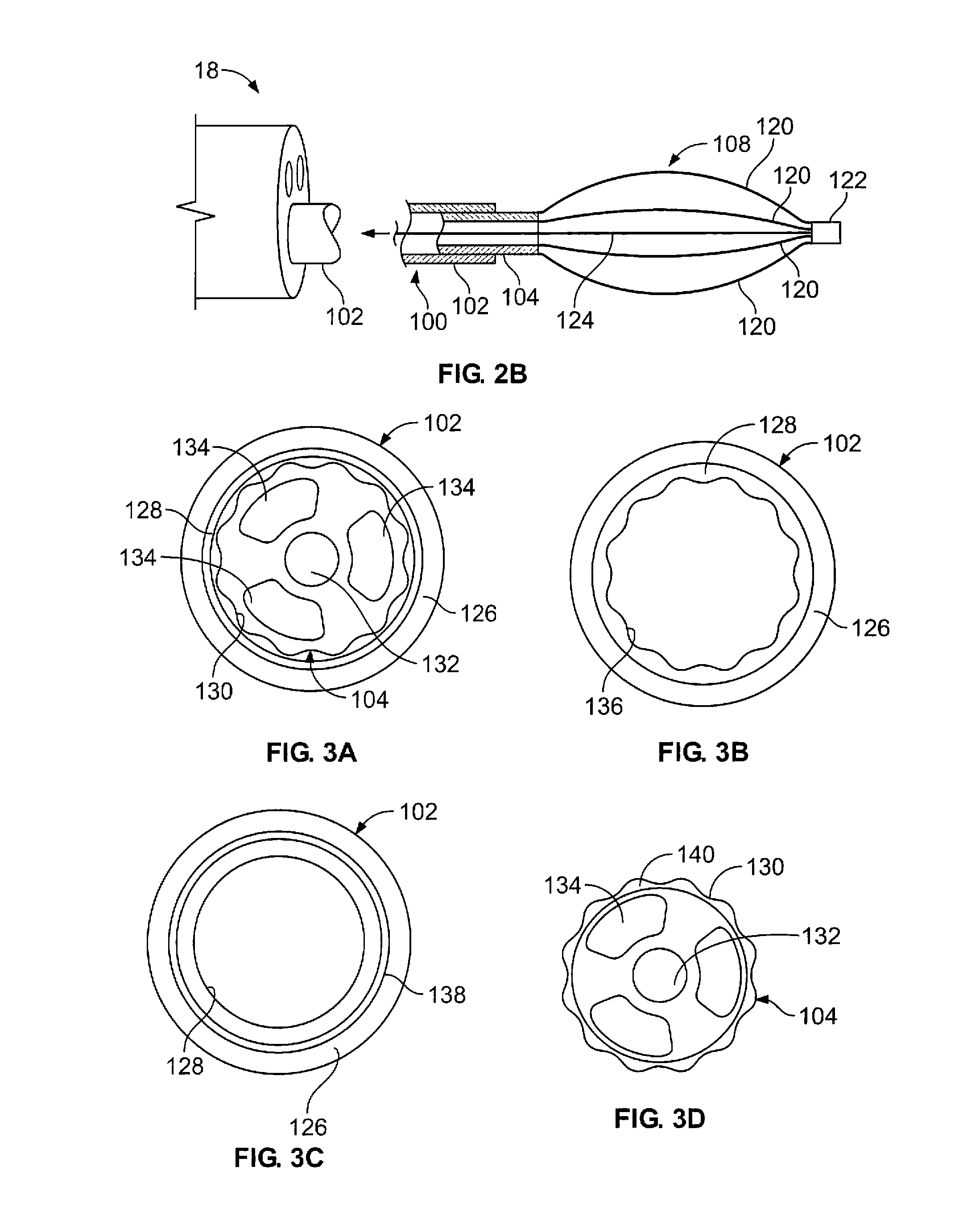
FIG. 3A illustrates a cross section taken from the sheath 102 and elongate shaft 104. As shown, the sheath 102 includes an outer layer 126 and an inner lubricious layer 128. The outer layer 126 may be any commonly known polymer such as Nylon, PTFE, etc. The lubricious layers 128 discussed herein may comprise a lubricious polymer (for example, HDPE, hydrogel, polytetrafluoroethylene). Typically, lubricious layer 128 will be selected for optimal pairing with the shaft 104. One means to select a pairing of polymers is to maximize the difference in Gibbs surface energy between the two contact layers. Such polymers may also be chose to give the lubricious layer 128 a different modulus of elasticity than the outer layer 126. For example, the modulus of the lubricious layer 128 may be higher or lower than that of the outer layer 126.
Alternatively, or in combination, the lubricious layers may comprise a fluid or liquid (e.g., silicone, petroleum based oils, food based oils, saline, etc.) that is either coated or sprayed on the interface of the shaft 104 and sheath 102. The coating may be applied at the time of manufacture or at time of use. Moreover, the lubricious layers 128 may even include polymers that are treated such that the surface properties of the polymer changes while the bulk properties of the polymer are unaffected (e.g., via a process of plasma surface modification on polymer, fluoropolymer, and other materials). Another feature of the treatment is to treat the surfaces of the devices with substances that provide antibacterial/antimicrobial properties.
In one variation of the invention, the shaft 104 and/or sheath 102 will be selected from a material to provide sufficient column strength to advance the expandable energy transfer element within the anatomy. Furthermore, the materials and or design of the shaft/sheath will permit a flexibility that allows the energy transfer element to essentially self-align or self-center when expanded to contact the surface of the body passageway. For example, when advanced through tortuous anatomy, the flexibility of this variation should be sufficient that when the energy transfer element expands, the shaft and/or sheath deforms to permit self-centering of the energy transfer element. It is noted that the other material selection and/or designs described herein shall aid in providing this feature of the invention.
FIG. 3A also depicts a variation of a shaft 104 for use in the present device. In this variation the shaft 104 includes a corrugated surface 130. It is envisioned that the corrugated surface 130 may include ribbed, textured, scalloped, striated, ribbed, undercut, polygonal, or any similar geometry resulting in a reduced area of surface contact with any adjoining surface(s). The corrugated surface 130 may extend over a portion or the entire length of the shaft 104. In addition, the shape of the corrugations may change at varying points along the shaft 104.
The shaft 104 may also include one or more lumens 132, 134. Typically, one lumen will suffice to provide power to the energy transfer elements (as discussed below). However, in the variation show, the shaft may also benefit from additional lumens (such as lumens 134) to support additional features of the device (e.g., temperature sensing elements, other sensor elements such as pressure or fluid sensors, utilizing different lumens for different sensor leads, and fluid delivery or suctioning, etc.). In addition the lumens may be used to deliver fluids or suction fluid to assist in managing the moisture within the passageway. Such management may optimize the electrical coupling of the electrode to the tissue (by, for example, altering impedance). Since the device is suited for use in tortuous anatomy, a variation of the shaft 104 may have lumens 134 that are symmetrically formed about an axis of the shaft. As shown, the additional lumens 134 are symmetric about the shaft 104. This construction provides the shaft 104 with a cross sectional symmetry that aid in preventing the shaft 104 from being predisposed to flex or bend in any one particular direction.
FIG. 3B illustrates another variation where the sheath 102 includes an outer layer 126 and a lubricious layer 128. However, in this variation the lubricious layer 128 also includes a corrugated surface 136. It is noted that any combination of the sheath 102 and shaft 104 may have a corrugated surface.
FIG. 3C illustrates yet another aspect of construction of a sheath 102 for use with the present device. In this variation, the sheath 102 includes a multi-layer construction having an outer layer 126, one or more middle layers 138. The middle layers 138 may be selected to have properties that transition between the outer layer properties and the lubricious layer properties, and improve the bonding between inner and outer layer. Alternatively, the middle layer 138 may be selected to aid in the column strength of the device. An example of the middle layer includes Plexar PX 306, 3060, and/or 3080.
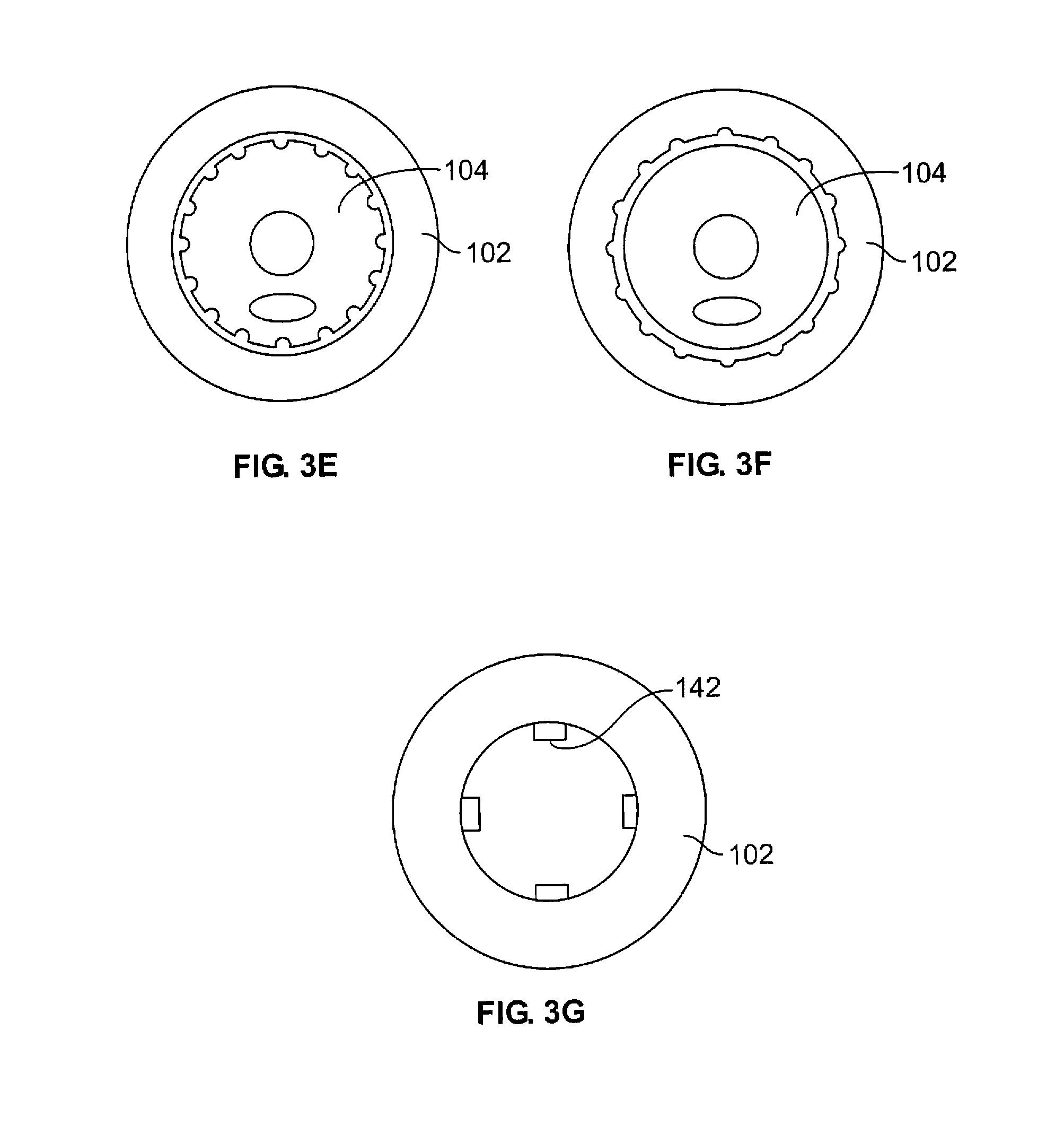
FIG. 3D depicts a variation of a shaft 104 for use with the devices described herein where the shaft outer surface comprises a lubricious layer 140. As illustrated, the shaft outer surface may also optionally have a corrugated surface 130. FIGS. 3E-3G illustrate additional variations of corrugated surfaces. As shown in FIGS. 3E and 3F, either or both the sheath 102 and the shaft 104 may have corrugated surfaces that are formed by interrupting the surface. Naturally, different shapes and configurations may be otherwise constructed. FIG. 3G illustrates a variation where the sheath 102 comprises protrusions or spacer 142 to separate the surfaces of the sheath/shaft.
FIGS. 4A-4D illustrate yet another feature that may be incorporated with any of the subject devices. FIG. 4A illustrates an example of an alignment component 150. In this variation, the alignment component 150 includes a plurality of seats 152 that nest electrode arms (not shown). As discussed herein, the seats 152 allow for improved control of the angular spacing of the alms. Moreover, the seats 152 permits design of a device in which the flexure length of each of the arms of a basket type device is uniform (even if the tolerance of each arm varies). Though the alignment component 150 is shown as having four seats 152, any number of seats may be employed.
The alignment component 150 also includes a stop 154. The stop 154 acts as a reference guide for placement of the arms as discussed below. In this variation, the stop 154 is formed from a surface of an end portion 158. This end portion 158 is typically used to secure the alignment component 150 to (or within) the sheath/shaft of the device. The alignment component 150 may optionally include a through hole or lumen 156.
FIG. 4B illustrates another variation of an alignment component 152. This variation is similar to the variation shown in FIG. 4A, with the difference being the length of the end portion 158. The smaller end portion 158 may optionally be employed when the component 150 is used at the distal end of the device. In such a case, the component 158 may not be attached to the sheath or shaft. In addition, the end portion 158 may optionally be rounded, for example, to minimize tissue trauma that may be caused by the end of the device.
The alignment components 150 of the present invention may be fabricated from a variety of polymers (such as nylon or any other polymer commonly used in medical devices), either by machining, molding, or by cutting an extruded profile to length. One feature of this design is electrical isolation between the legs, which may also be obtained using a variation of the invention that employs a ceramic material for the alignment component. However, in one variation of the invention, an alignment component may be fabricated from a conductive material (e.g., stainless steel, polymer loaded with conductive material, or metallized ceramic) so that it provides electrical conductivity between adjacent electrode legs. In such a case, a power supply may be coupled to the alignment component, which then electrically couples all of the legs placed in contact with that component. The legs may be attached to the conductive alignment component with conductive adhesive, or by soldering or welding the legs to the alignment component. This does not preclude the legs and alignment component form being formed from one piece of metal.
Devices of the present invention may have one or more alignment components. Typically the alignment components are of the same size and/or the angular spacing of the seats is the same. However, variations may require alignment components of different sizes and/or different angular spacing. Another variation of the invention is to have the seats at an angle relative to the axis of the device, so as to form a helically shaped energy delivery element.
FIG. 4C illustrates another variation of an alignment component 150. In this variation, the alignment component 150 includes four seats 152. This variation includes an alignment stop 154 that protrudes from the surface of the component 150. In addition, the end portion 158 of the alignment component 150 is also of a cross section that may improve strength of the connection between the component and the sheath/shaft. In this case, the end portion 158 allows for crimping of the sheath/shaft. Optionally as shown, radial protrusions 178 at the right of the end portion 158 may be included to allow heat bonding of the alignment component to the shaft. In this case, the shaft may be a polymer with a melting temperature lower than that of the alignment component. When constrained to be coaxial, heat, and if necessary axial pressure, may be applied to join the two components.
FIG. 4D illustrates the protrusion-type stop 154 that retains a notch 162 of the electrode leg 160. This mode of securing the electrode leg 160 provides a "redundant-type" joint. In one example, the leg 160 is secured to the alignment component 150 using a sleeve (not shown) placed over both the leg 160 and alignment component 150 with or without the use of an adhesive within the sleeve. The notch 162 in the leg 160 is placed around the protrusion-type-stop 154. As a result, the notch-stop interface prevents the leg from being pulled from the device and is especially useful to prevent the proximal or near ends of the legs from separating from the device. It is noted that this safety feature is especially important when considering that if the proximal/near ends of the legs separate and hook on the anatomical passage, it may be difficult or impossible to remove the device from the passage. Such a failure may require significant medical intervention.
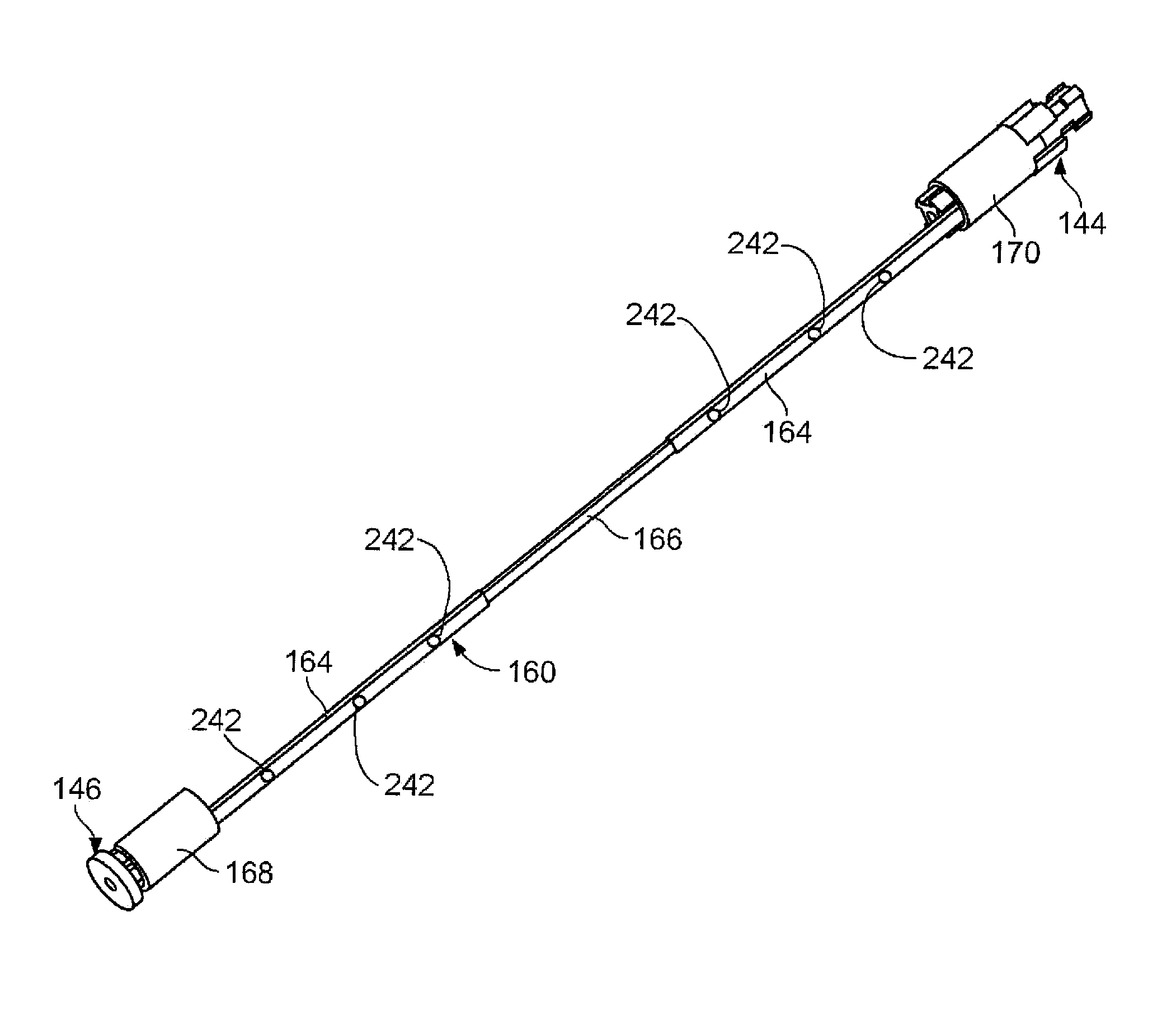
FIG. 4E illustrates one example of a leg 160 affixed to near/proximal and far/distal alignment components 144, 146. As shown, the leg 160 may have an insulated portion 164 and an exposed portion 166 that form electrodes. The near and far ends of the leg 160 are secured to respective alignment components 144, 146. In this example, sleeves 168 and 170 cover the leg and alignment component. As noted above, one or both of the alignment components may be electrically conductive to provide power to the electrodes. Furthermore, adhesive (e.g., cyanoacrylate, UV-cured acrylic, epoxy, or any such adhesive) may also be used to secure the leg to the components.
Additionally, the alignment components may be designed such that the sleeves may be press or snap fit onto the alignment components, eliminating the need for adhesively bonding the sleeves to the alignment components. FIG. 4F illustrates a perspective view of an end portion of an alignment component 150 having one or more slots 186 to create end portion segments 184. The slots 186 permit deflection of the end portion segments 184 to allow sliding of a sleeve or hypotube (either a near or far sleeve 168 or 170) over the end portion. FIG. 4G shows a cross sectional view of the component 150 of FIG. 4F. As shown, once advanced over the end portion segment 184, the sleeve or hypotube becomes secured to the component 150. To lock the sleeve in place, an insert or wire member 124 (not shown) is placed in the through hole or lumen 156. The insert or wire member prevents inward deflection of the end portion segments 184 thereby ensuring that the sleeve or hypotube remains secured to the component 150.
FIG. 5A shows a cross sectional view of two legs 160 attached to alignment components 144, 146. The sheath and shaft have been omitted for clarity. The flexure length 164 of the leg 160 is defined as the length between the alignment components 144, 146 over which the leg may flex when the proximal and distal ends are moved closer to one another. As noted above, the alignment components permit the flexure length 164 of the legs 160 to be uniform even if the leg lengths vary. The flexure length 164 is essentially set by the longest leg, the shorter legs may float between the stops 154 of the alignment components 144, 146. As an additional measure to prevent the legs 160 from inverting, the lengths of the sleeves 168 and 170 may be selected to be less than the length of the respective alignment components 144, 146 (as shown in the figure). The tendency of the leg to deflect outward can be improved by selecting the sleeve length as such. When the legs 160 expand they are supported by their respective seat on the interior side but unsupported on outer side. In yet another variation, the the seats can slant to predispose the arms to deflect in a desired direction. For example, as shown in FIG. 5C, the seats 152 can slant as shown to predispose the legs 160 to outward deflection. Such a construction can be accomplished by machining or by drafting a molded part in the direction of the catheter axis. As shown in FIG. 5D, the leg can have a slight bend or shape that predisposes the legs to bow outward.
FIG. 5B illustrates the variation of FIG. 5A in an expanded state. As shown, the device may have a wire 124 or other similar member that permits movement of the far alignment component 146 relative to the near alignment component 144. As noted herein, the wire 124 may be electrically conductive to provide power to electrodes on the device. FIG. 5B also illustrates a ball tip 148 at the end of the device. The ball tip 148 may serve as a means to secure the wire 124 as well as providing an a traumatic tip for the device.
Variations of the wire 124 may include a braided or coiled wire. The wire may be polymer coated or otherwise treated to electrically insulate or increase lubricity for easier movement within the device.
To expand the energy transfer element 108, the wire 124 may be affixed to a handle 106 and actuated with a slide mechanism 114 (as shown in FIG. 2A.) In an alternative design, the wire 124 may be affixed between the handle 106 and the distal end of the energy transfer element 108. In such a case, the slide mechanism 114 maybe affixed to the shaft 104. Movement of the slide mechanism 114 causes expansion of the element 108 as the shaft causes movement of the proximal end of the energy transfer element (being fixed to the shaft) relative to the distal end of the energy transfer element (being fixed to the wire 124. In an additional variation, movement of the slide 114 may have two outcomes: 1) advancing the energy transfer element out of the sheath; and 2) subsequently expanding the energy transfer element. Such constructions are disclosed in U.S. patent application Ser. No. 09/436,455 filed Nov. 8, 1999 the entirety of which is incorporated by reference herein.
FIG. 6A illustrates a variation of an energy transfer element 108 in which the legs 160 have a pre-determined shape. This shape may be selected as required for the particular application. As shown, the predetermined shape provides a certain length of the electrode 166 that may be useful for treatment of a long section of tissue.
FIG. 6B illustrates another variation of the energy transfer element 108. In this variation, the legs 160 extend out of openings 180 in the sheath 102 (in other variations, the legs may extend out of openings in the shaft). Accordingly, the alignment components and other parts of the device would be located within the sheath 102.
FIG. 6C illustrates yet another variation of an energy transfer element 108. In this variation, the basket is connected at a proximal end and opened at a distal end. The electrode legs 160 only have a single alignment component 150. The conductive member (or wire) may be located within the shaft 104. In this variation, advancement of the energy transfer element 108 out of the sheath 102 causes expansion of the element. The energy transfer elements may be predisposed or spring loaded to bow outward when advanced from the sheath.
FIG. 7A illustrates an example of a leg 160 with an energy element 182 coiled around the leg 160. In this example, the energy element 182 uses conductive heating and comprises a resistance heating element coiled around the leg 160. FIG. 7B illustrates a variation of the invention having an RF electrode attached to the basket leg 160. The RF electrode may be attached to the basket leg 160 via the use of a fastener. For example, the electrode may be attached via the use of a heat shrink fastener, (e.g., polymeric material such as PET or polyethylene tubing). Alternatively, as discussed above, the entire leg may be a conductive medium where a non-conductive coating insulates the majority of the leg leaving the electrode portion uninsulated. Further examples of energy transfer elements configurations include paired bipolar electrodes, where the pairs are leg to leg or within each leg, and large matrices of paired electrodes affixed to a variety of expanding members (balloons, mechanisms, etc.)
FIG. 7C illustrates a variation of the invention having thermocouple leads 172 attached to an electrode 166 or leg of the device. The leads may be soldered, welded, or otherwise attached. This variation of the invention shows both leads 172 of the thermocouple 174 attached in electrical communication to a leg 160 at separate joints (or the leads may be separated but the solder on each connection actually flows together). In this case, the temperature sensor is at the surface of the leg. This variation provides a safety measure in case either joint becomes detached, the circuit will be open and the thermocouple 174 stops reading temperature. Such a condition may be monitored via the power supply and allow a safe shutdown of the system.
By spacing the leads of the thermocouple closely together to minimize temperature gradients in the energy transfer element between the thermocouple leads, thermoelectric voltage generated within the energy transfer element does not compromise the accuracy of the measurement. The leads may be spaced as close together as possible while still maintaining a gap so as to form an intrinsic junction with the energy transfer element. In another variation of the device, the thermocouple leads may be spaced anywhere along the tissue contacting region of the energy transfer element. Alternatively, or in combination, the leads may be spaced along the portion of an electrode that remains substantially straight. The intrinsic junction also provides a more accurate way of measuring surface temperature of the energy transfer element, as it minimizes the conduction error associated with an extrinsic junction adhered to the device.
The thermocouple leads may be attached to an interior of the leg or electrode. Such a configuration protects the thermocouple as the device expands against tissue and protects the tissue from potential trauma. The device may also include both of the thermocouple leads as having the same joint.
The devices of the present invention may use a variety of temperature sensing elements (a thermocouple being just one example, others include, infrared sensors, thermistors, resistance temperature detectors (RTDs), or any other component capable of detecting temperatures or changes in temperature). The temperature detecting elements may be placed on a single leg, on multiple legs or on all of the legs.
The present invention may also incorporate a junction that adjusts for misalignment between the branching airways or other body passages. This junction may be employed in addition to the other features described herein. FIG. 8A illustrates a device 100 having such a junction 176 allowing alignment of the device to closely match the alignment of the airway. It is noted that the present feature also benefits those cases in which the pathway and target site are offset as opposed to having an angular difference.
The junction 176 helps to eliminate the need for alignment of the axis of the active element 108 with the remainder of the device in order to provide substantially even tissue contact. The junction may be a joint, a flexure or equivalent means. A non-exhaustive listing of examples is provided below.
The legs 160 of the energy transfer element may have various shapes. For example, the shapes may be round, rounded or polygonal in cross section. Additionally, each leg may change cross section along its axis, providing for, for example, electrodes that are smaller or larger in cross section that the distal and proximal portions of each leg. This would provide a variety of energy delivery characteristics and bending profiles, allowing the design to be improved such that longer or wider electrode configurations can be employed. For example, as shown in FIG. 7D, if the cross-sectional thickness of the electrode portion 166 of the leg 160 is greater than the cross-sectional thickness of the distal and proximal portions of the leg, the leg would be predisposed to bow outward in the distal and proximal sections, while remaining flatter in the electrode area of the leg, potentially providing improved tissue contact.
As for the action the junction enables, it allows the distal end of the device to self-align with the cavity or passageway to be treated, irrespective of the alignment of the access passageway. FIG. 8A illustrates an example of where the access passageway and passageway to be treated are misaligned by an angle .alpha.. In the example shown in FIG. 8B, the misalignment angle .alpha. is greater than the angle illustrated in FIG. 8A. Yet, the energy transfer element 108 of the treatment device 100 remains substantially aligned with the target area.
FIGS. 8C and 8D illustrate an additional variation of the junction 176. In this variation the junction 176 may be reinforced with a reinforcing member 230. The reinforcing member may have some degree of flexibility to navigate the tortuous anatomy, but the flexibility will be less than the junction 176. As shown in FIG. 8C, the reinforcing member 230 maintains the device shaft 104 in an aligned position, preferably for insertion, removal, and or navigation of the device. When desired, the reinforcing member 230 may be removed from the junction 176 as illustrated in FIG. 8D. Accordingly, upon removal, the device is free to flex or orientate as desired. Furthermore, the reinforcing member may be reinserted within the junction 176 when repositioning or removing the device from the target site. In additional variations, it is contemplated that the reinforcing member may be placed external to the device/junction.
FIGS. 9A-9I illustrate additional junctions for use in the devices described herein. As for these examples, FIG. 9A illustrates a junction 176 in the form of a plurality of turns or coils 200 of a spring. The coil offers a flexure with 3-dimensional freedom allowing realignment of the active end of the subject device in any direction. Of course, a simple hinge or universal joint may also be employed.
The length of the junction (whether a spring junction or some other structure) may vary. Its length may depend on the overall system diameter. It may also depend on the degree of compliance desired. For example, with a longer effective junction length (made by extending the coil with additional turns), the junction becomes less rigid or more "floppy".
In any case, it may be desired that the junction has substantially the same diameter of the device structure adjacent the junction. In this way, a more a traumatic system can be provided. In this respect, it may also be desired to encapsulate the junction with a sleeve or covering if they include open or openable structures. Junction 176 shown in FIGS. 8A and 8B is illustrated as being covered. A covering can help avoid contaminating the joint with body fluid or debris which could compromise junction function.
Some of the junctions are inherently protected. Junction 176 shown in FIG. 9B comprises a polymer plug 220 or a section of polymer having a different flexibility or durometer than adjacent sections. When a separate piece of polymer is to be employed, it can be chemically, adhesively, or heat welded to adjacent structure; when the junction is formed integrally, this may be accomplished by selective vulcanizing, or reinforcement (even with a braid or by other means of forming a composite structure). Generally, it is noted that any connection of pieces or construction provided may be produced by methods known by those with skill in the art.
As for junction 176 shown in FIG. 9C, it is formed by removing sections of material from the body of the device. Openings 218 formed at the junction may be left empty, covered or filled with a more compliant material. FIG. 9D also shows a junction 176 in which openings are provided to provide increased flexibility. Here, openings 218 are offset from each other to form a sort of flexible universal joint. In either junction variation shown in FIG. 9C or 9D, the size, number shape, etc. of the opening may vary or be tuned as desired.
FIG. 9E shows a junction 176 in the form of a bellows comprising plurality of pleats 216. Here too, the number of pleats, etc. may be varied to achieve desirable performance.
Junction 176 in FIG. 9F shows a true "joint" configuration. In this case, it is a universal joint provided by ball 204 and socket 206. These elements may be held together by a tie wire 208, possibly with caps 210. Other configurations are possible as well.
FIG. 9G illustrates a junction 176 in the form of a reduced diameter section 202. This variation offers greater flexibility by virtue of its decreased moment of inertia at the junction. While section 202 is integrally formed, the related junction 176 in FIG. 9H is formed from a hypotube or wire 212 having an exposed junction section 214 on the shaft 104. Variations of the invention will permit a junction having a reduced bending moment of inertia section as compared to the remainder of the device and/or shaft of the device. Reducing the bending moment of inertia may be accomplished in any number of ways. For example, there could be an area of reduced diameter, a section of material having a lower modulus, a section having a different shape, a flexible joint structure, etc. It should be noted that there are many additional ways to reduce the bending moment that will be readily apparent to those skilled in the art viewing the invention disclosed herein.
Yet another junction example is provided in FIG. 9I. Here junction 176 comprises a plurality of wires 222, 224, 226. In one variation, the wires simply offer increased flexibility of the junction. In another variation, the wires serve as an "active" or "dynamic" junction. The wires may be adjusted relative to one another to physically steer the distal end of the device. This junction may be manipulated manually with an appropriate user interface--especially one, like a joy-stick, that allows for full 3-dimensional or rotational freedom--or it may be controlled by automation using appropriate hardware and software controls. Of course, other "dynamic" junctions are possible as well.
FIG. 9J shows another joint configuration 176 employing an external sleeve 262 between sections of the shaft 104. A moveable wire 124 to actuate a distal basket or the like is also shown. The space between the wire and sleeve may be left open as shown, or filled in with a flexible polymer 264, such as low durometer urethane, a visco-elastic material, etc. Though not necessary, providing an internal member may improve system pushability. The sleeve itself will typically be a polymeric sleeve. It may be heat-shrink material such as PET tubing; it may be integrally formed with either catheter body portion and press fit or slip fit and glued over other etc.
Another variation of the junctions includes junctions variations where the shaft 104 is "floppy" (i.e., without sufficient column strength for the device to be pushable for navigation). In FIG. 10A, a tether 232 connects energy transfer element 108 to the shaft 104 of the device 100. The tether may simply comprise a flexible wire or cable, it may comprise a plurality of links, etc. The tether variation of the invention also accommodates relative motion between the device and the body (e.g., tidal motion of breathing, other muscle contractions, etc.) The tether permits the device to move relative to its intended treatment location unless the user desires and uses the tether or the sheath to pull the device back or drive it forward. The tether may have an alignment component (not illustrated) at the near end of the energy transfer element 108.
To navigate such a device to a treatment site, the energy transfer element 108 and tether 232 may be next to or within the sheath 102. In this manner, the column strength provided by the sheath allows for advancement of the active member within the subject anatomy.
The same action is required to navigate the device shown in FIG. 10B. What differs in this variation of the invention, however, is that the "tether" is actually a continuation of a highly flexible shaft 104. In this case, the shaft 104 of the device is shown with a thicker or reinforced wall. In such a device, the shaft carries the compressive loads on the device back to its distal end.
Like the device in FIG. 10B, the devices in FIGS. 10C and 10D have highly flexible shafts 104. However, instead of a stiffening external sheath, the device may employ a stiffening obturator 230 within a lumen of the shaft 104. As shown in FIG. 10C, when the obturator 230 fills the lumen, the device is relatively straight or stiff. When the shaft is withdrawn as shown in FIG. 10D, the distal end of the device is "floppy" or easily conformable to the subject anatomy. With the shaft advanced substantially to the end of the device, it offers ease of navigation; when withdrawn, it offers a compliant section according to an aspect of the present invention.
FIGS. 11A-11C illustrate yet another aspect of the invention in which a treatment device is equipped with an illumination source 242. As noted above, the illumination source 242 may be configured to provide additional light when the device is used without a scope or to supplement the illumination of the scope. Variations of the invention may include devices having one or more illumination sources 242 that are coupled to an illumination supply 241) that generates the light energy externally to the device (e.g., via a fiber or other type of light conductor). Alternatively, or in combination, the illumination source 242 may generate the light at the distal portion of the device (e.g., via a light emitting diode, etc). It should be noted that although FIG. 11, depicts the illumination supply 240 as being separate from the controller and energy generator, the illumination supply 240 may be integrated into the controller or energy generator.
FIG. 11A illustrates a variation of a system according to the present invention as shown in FIG. 2A above, with the addition of an illumination supply 240 and a device with one or more illumination sources 242. As noted above, a separate illumination supply 240 is optional as the illumination supply 240 may be incorporated with other components of the system (e.g., device controller, generator, or other).
FIG. 11B shows a variation of a device as shown in FIG. 8A. However, in this variation, the device includes an illumination source 242. As shown, the illumination source 242 may be located on a tip 122 of the device, on the shaft 104, on the sheath 102, on the energy transfer element (as shown in FIG. 11C) or in any combination thereof. Although not illustrated, the illumination source may be placed on or adjacent to a center wire 124 of the basket member 108. For example, an LED may be placed on the wire, or an optical fiber may be placed adjacent to or wrapped around the wire 124. Alternatively, a filament or other similar type component may be affixed to the wire in a similar manner, where the filament generates light of a particular wavelength.
FIG. 11C illustrates just one example of a basket leg variation as shown in FIG. 4E above, with the addition of an illumination source 242 that is placed on the leg. In each of the above cases, the illumination source 242 may be an end of a fiber type element that extends through the device and terminates at the illumination source 242 (alternatively or in combination, this variation may include a lens or cover at the termination of the fiber). The illumination source may also comprise a component that emits energy or light (such as a light emitting diode).
It is further contemplated that the illumination source 242 may be placed on a single side of the device or may be placed such that all walls of the airway are illuminated.
It is noted that variations of the device may include a single illumination source 242 or multiple illumination sources 242. The illumination source(s) 242 may be configured to provide a single or multiple wavelength of light depending upon the particular application. For example, the device may be configured to provide illumination that is visible light, or white light. The illumination can be a single visible color such as red, green, blue, yellow, or a combination. The illumination may be a non-visible wavelength that is made visible by some type or filter or other such means on the scope or viewing monitor for the scope.
Variations of the invention include aiming or positioning the illumination source rearward to aid in light collection by the scope, use of a flex circuit to carry LED and have traces, use of LED lens cap as an a traumatic distal tip.
In addition, certain wavelengths may afford separation from red and orange (e.g., 590 nm, 570 nm, 470 nm or yellow, green, and blue. These colors may offer better distinction when used in airways. In variations of the invention using light emitting diodes (LEDS), the may be commercially available in surface mount configurations having a size that is suited for a device that must fit in a 2 mm working channel. See for example, www.kingbright-led.com, surface mount LED package, APHHS1005.
At the very least, LED may make it easier for the practitioner to identify treated areas within the airway, such as tissue that is blanched or otherwise marked by the application of energy. In these cases, the reflectance of this tissue may be different than surrounding areas.
The invention may also be used with polarizing filters or polarizing fibers to differentiate treated from untreated tissue. Use of circularly polarized filters may be preferred in such a case to eliminate the need for rotation of the filters. In yet another approach the illumination supply/source may use coherent sources of light such as solid state or optical lasers. In the case of a solid state laser, the laser source may actually be placed on the distal end of the device rather than being transmitted via a fiber.
Furthermore, use digital (electronic) filtering of the image from CCD chip mounted at the end of the bronchoscope may permit filtering for desirable wavelengths and/or the image could be amplified to enable discernment. In addition, so long as long the system delivers light containing a broad spectrum of wavelengths, electronic or manual filtering may allow for filtering out any undesirable components. In additional variations, a filter or filters may be placed on the end of the device.
As for other details of the present invention, materials and manufacturing techniques may be employed as within the level of those with skill in the relevant art. The same may hold true with respect to method-based aspects of the invention in terms of additional acts a commonly or logically employed. In addition, though the invention has been described in reference to several examples, optionally incorporating various features, the invention is not to be limited to that which is described or indicated as contemplated with respect to each variation of the invention.
Various changes may be made to the invention described and equivalents (whether recited herein or not included for the sake of some brevity) may be substituted without departing from the true spirit and scope of the invention.
It is contemplated that, where possible, combinations of aspects of each embodiment or combinations of the embodiments themselves are within the scope of the invention.
Reference to a singular item, includes the possibility that there are plural of the same items present. More specifically, as used herein and in the appended claims, the singular forms "a," "and," "said," and "the" include plural referents unless the context clearly dictates otherwise.
* * * * *
References
D00000
D00001
D00002
D00003
D00004
D00005
D00006
D00007
D00008
D00009
D00010
D00011
D00012
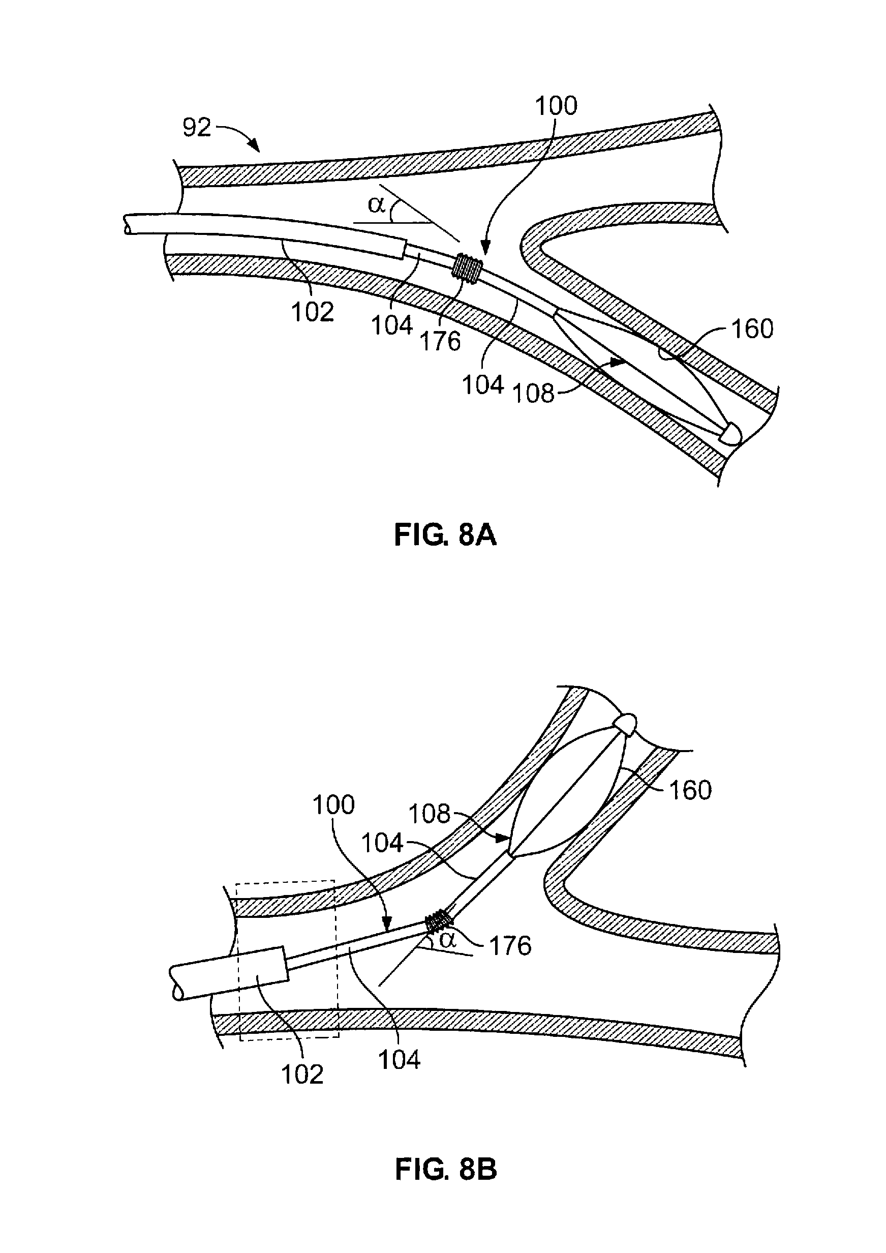
D00013
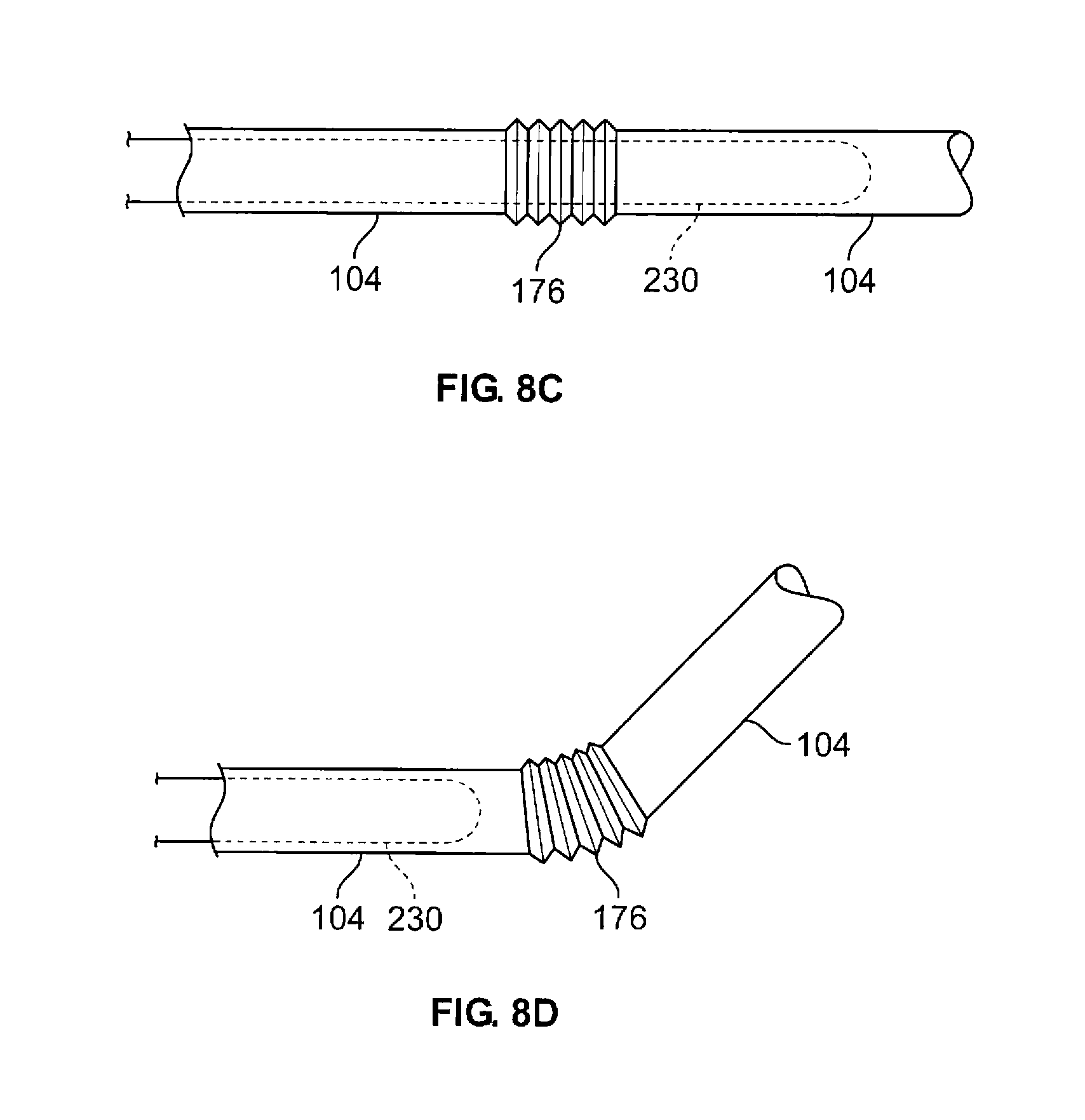
D00014

D00015

D00016
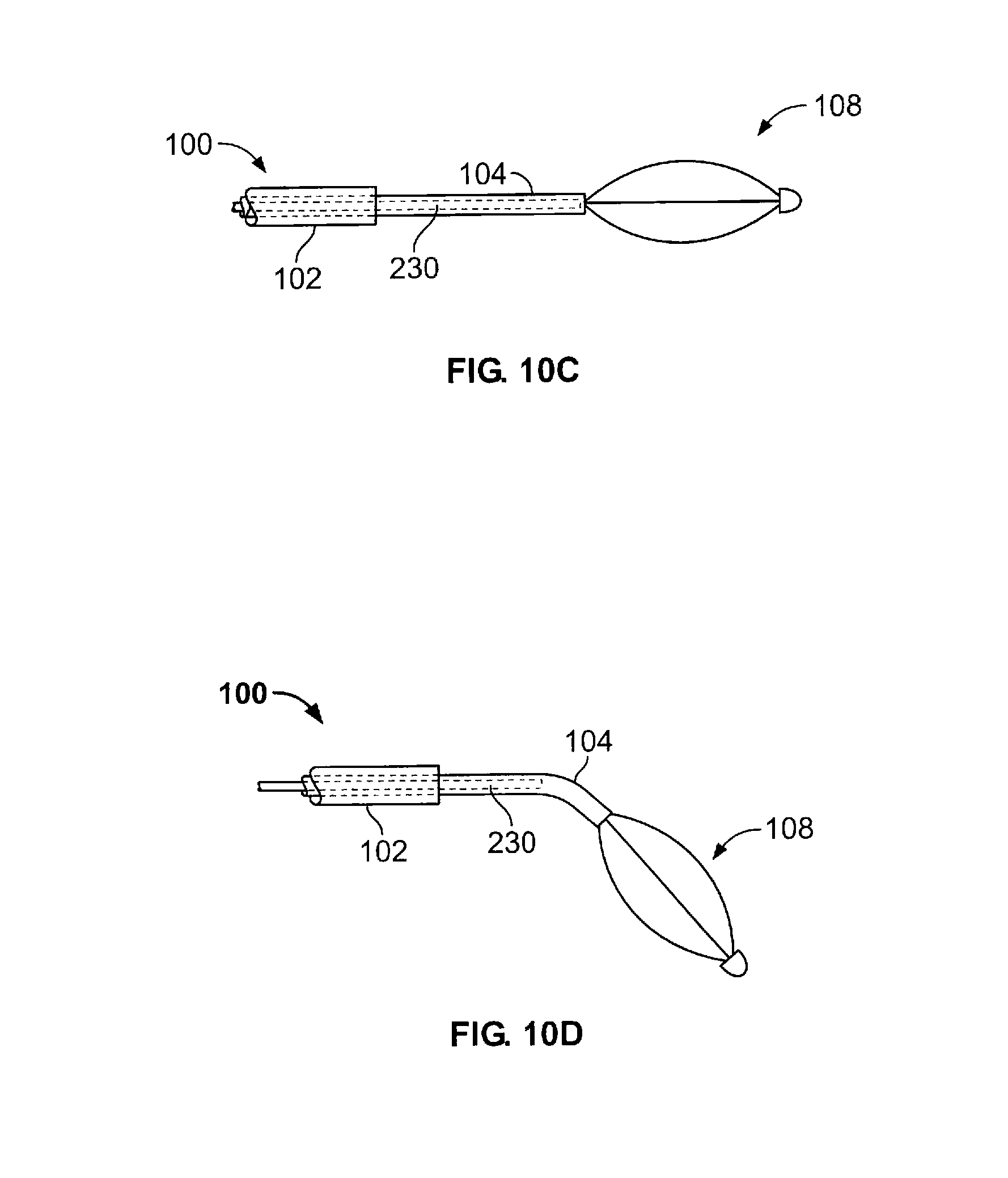
D00017

D00018

XML
uspto.report is an independent third-party trademark research tool that is not affiliated, endorsed, or sponsored by the United States Patent and Trademark Office (USPTO) or any other governmental organization. The information provided by uspto.report is based on publicly available data at the time of writing and is intended for informational purposes only.
While we strive to provide accurate and up-to-date information, we do not guarantee the accuracy, completeness, reliability, or suitability of the information displayed on this site. The use of this site is at your own risk. Any reliance you place on such information is therefore strictly at your own risk.
All official trademark data, including owner information, should be verified by visiting the official USPTO website at www.uspto.gov. This site is not intended to replace professional legal advice and should not be used as a substitute for consulting with a legal professional who is knowledgeable about trademark law.