Method for assisting user input to a device
Ciesla , et al. December 31, 2
U.S. patent number 8,619,035 [Application Number 13/024,241] was granted by the patent office on 2013-12-31 for method for assisting user input to a device. This patent grant is currently assigned to Tactus Technology, Inc.. The grantee listed for this patent is Craig Michael Ciesla, Nathaniel Mark Saal, Micah B. Yairi. Invention is credited to Craig Michael Ciesla, Nathaniel Mark Saal, Micah B. Yairi.


| United States Patent | 8,619,035 |
| Ciesla , et al. | December 31, 2013 |
| **Please see images for: ( Certificate of Correction ) ** |
Method for assisting user input to a device
Abstract
A method for assisting user input to a device, comprising the steps of providing a user interface to retrieve a user input, providing a tactile interface layer that defines a surface and includes a volume of fluid and a displacement device that manipulates the volume of fluid to deform a plurality of particular regions of the surface into tactilely distinguishable formations that each represent a key of a key interface, allowing the user to provide input through the key interface, predicting a subsequent key input when a user provides an input through the key interface, and manipulating the volume of fluid to deform the plurality of particular regions into one of two types of tactilely distinguishable formations: a first type for tactilely distinguishable formations that represent a predicted key and a second type for tactilely distinguishable formations that represent an unpredicted key.
| Inventors: | Ciesla; Craig Michael (Mountain View, CA), Yairi; Micah B. (Daly City, CA), Saal; Nathaniel Mark (Palo Alto, CA) | ||||||||||
|---|---|---|---|---|---|---|---|---|---|---|---|
| Applicant: |
|
||||||||||
| Assignee: | Tactus Technology, Inc.
(Fremont, CA) |
||||||||||
| Family ID: | 45555779 | ||||||||||
| Appl. No.: | 13/024,241 | ||||||||||
| Filed: | February 9, 2011 |
Prior Publication Data
| Document Identifier | Publication Date | |
|---|---|---|
| US 20120032886 A1 | Feb 9, 2012 | |
Related U.S. Patent Documents
| Application Number | Filing Date | Patent Number | Issue Date | ||
|---|---|---|---|---|---|
| 61303214 | Feb 10, 2010 | ||||
| Current U.S. Class: | 345/168; 340/407.2; 345/156 |
| Current CPC Class: | G06F 3/016 (20130101); G06F 3/0202 (20130101); G06F 3/0237 (20130101) |
| Current International Class: | G06F 3/02 (20060101) |
| Field of Search: | ;345/156-184 ;340/407.2 |
References Cited [Referenced By]
U.S. Patent Documents
| 3034628 | May 1962 | Wadey |
| 3659354 | May 1972 | Sutherland |
| 3759108 | September 1973 | Borom et al. |
| 3780236 | December 1973 | Gross |
| 3818487 | June 1974 | Brody et al. |
| 4109118 | August 1978 | Kley |
| 4209819 | June 1980 | Seignemartin |
| 4290343 | September 1981 | Gram |
| 4307268 | December 1981 | Harper |
| 4467321 | August 1984 | Volnak |
| 4477700 | October 1984 | Balash et al. |
| 4517421 | May 1985 | Margolin |
| 4543000 | September 1985 | Hasenbalg |
| 4700025 | October 1987 | Hatayama et al. |
| 4920343 | April 1990 | Schwartz |
| 5194852 | March 1993 | More et al. |
| 5195659 | March 1993 | Eiskant |
| 5212473 | May 1993 | Louis |
| 5222895 | June 1993 | Fricke |
| 5286199 | February 1994 | Kipke |
| 5369228 | November 1994 | Faust |
| 5412189 | May 1995 | Cragun |
| 5459461 | October 1995 | Crowley et al. |
| 5488204 | January 1996 | Mead et al. |
| 5496174 | March 1996 | Garner |
| 5666112 | September 1997 | Crowley et al. |
| 5717423 | February 1998 | Parker |
| 5729222 | March 1998 | Iggulden et al. |
| 5742241 | April 1998 | Crowley et al. |
| 5754023 | May 1998 | Roston et al. |
| 5766013 | June 1998 | Vuyk |
| 5767839 | June 1998 | Rosenberg |
| 5835080 | November 1998 | Beeteson et al. |
| 5880411 | March 1999 | Gillespie et al. |
| 5889236 | March 1999 | Gillespie et al. |
| 5917906 | June 1999 | Thornton |
| 5943043 | August 1999 | Furuhata et al. |
| 5977867 | November 1999 | Blouin |
| 5982304 | November 1999 | Selker et al. |
| 6067116 | May 2000 | Yamano et al. |
| 6154198 | November 2000 | Rosenberg |
| 6154201 | November 2000 | Levin et al. |
| 6160540 | December 2000 | Fishkin et al. |
| 6169540 | January 2001 | Rosenberg et al. |
| 6188391 | February 2001 | Seely et al. |
| 6218966 | April 2001 | Goodwin et al. |
| 6243074 | June 2001 | Fishkin et al. |
| 6243078 | June 2001 | Rosenberg |
| 6268857 | July 2001 | Fishkin et al. |
| 6271828 | August 2001 | Rosenberg et al. |
| 6300937 | October 2001 | Rosenberg |
| 6310614 | October 2001 | Maeda et al. |
| 6323846 | November 2001 | Westerman et al. |
| 6337678 | January 2002 | Fish |
| 6354839 | March 2002 | Schmidt et al. |
| 6356259 | March 2002 | Maeda et al. |
| 6359572 | March 2002 | Vale |
| 6366272 | April 2002 | Rosenberg et al. |
| 6369803 | April 2002 | Brisebois et al. |
| 6384743 | May 2002 | Vanderheiden |
| 6414671 | July 2002 | Gillespie et al. |
| 6429846 | August 2002 | Rosenberg et al. |
| 6437771 | August 2002 | Rosenberg et al. |
| 6462294 | October 2002 | Davidson et al. |
| 6469692 | October 2002 | Rosenberg |
| 6486872 | November 2002 | Rosenberg et al. |
| 6498353 | December 2002 | Nagle et al. |
| 6501462 | December 2002 | Garner |
| 6509892 | January 2003 | Cooper et al. |
| 6573844 | June 2003 | Venolia et al. |
| 6636202 | October 2003 | Ishmael, Jr. et al. |
| 6639581 | October 2003 | Moore et al. |
| 6655788 | December 2003 | Freeman |
| 6657614 | December 2003 | Ito et al. |
| 6667738 | December 2003 | Murphy |
| 6681031 | January 2004 | Cohen et al. |
| 6686911 | February 2004 | Levin et al. |
| 6697086 | February 2004 | Rosenberg et al. |
| 6700556 | March 2004 | Richley et al. |
| 6703924 | March 2004 | Tecu et al. |
| 6743021 | June 2004 | Prince et al. |
| 6788295 | September 2004 | Inkster |
| 6819316 | November 2004 | Schulz et al. |
| 6850222 | February 2005 | Rosenberg |
| 6861961 | March 2005 | Sandbach et al. |
| 6877986 | April 2005 | Fournier et al. |
| 6881063 | April 2005 | Yang |
| 6930234 | August 2005 | Davis |
| 6937225 | August 2005 | Kehlstadt et al. |
| 6975305 | December 2005 | Yamashita |
| 6979164 | December 2005 | Kramer |
| 6982696 | January 2006 | Shahoian |
| 6995745 | February 2006 | Boon et al. |
| 7027032 | April 2006 | Rosenberg et al. |
| 7056051 | June 2006 | Fiffie |
| 7061467 | June 2006 | Rosenberg |
| 7064655 | June 2006 | Murray et al. |
| 7081888 | July 2006 | Cok et al. |
| 7096852 | August 2006 | Gregorio |
| 7102541 | September 2006 | Rosenberg |
| 7104152 | September 2006 | Levin et al. |
| 7106305 | September 2006 | Rosenberg |
| 7106313 | September 2006 | Schena et al. |
| 7109967 | September 2006 | Hioki et al. |
| 7112737 | September 2006 | Ramstein |
| 7113166 | September 2006 | Rosenberg et al. |
| 7116317 | October 2006 | Gregorio et al. |
| 7124425 | October 2006 | Anderson, Jr. et al. |
| 7129854 | October 2006 | Arneson et al. |
| 7131073 | October 2006 | Rosenberg et al. |
| 7136045 | November 2006 | Rosenberg et al. |
| 7138977 | November 2006 | Kinerk et al. |
| 7138985 | November 2006 | Nakajima |
| 7143785 | December 2006 | Maerkl et al. |
| 7144616 | December 2006 | Unger et al. |
| 7148875 | December 2006 | Rosenberg et al. |
| 7151432 | December 2006 | Tierling |
| 7151527 | December 2006 | Culver |
| 7151528 | December 2006 | Taylor et al. |
| 7154470 | December 2006 | Tierling |
| 7158112 | January 2007 | Rosenberg et al. |
| 7159008 | January 2007 | Wies et al. |
| 7161276 | January 2007 | Face |
| 7161580 | January 2007 | Bailey et al. |
| 7168042 | January 2007 | Braun et al. |
| 7176903 | February 2007 | Katsuki et al. |
| 7182691 | February 2007 | Schena |
| 7191191 | March 2007 | Peurach et al. |
| 7193607 | March 2007 | Moore et al. |
| 7195170 | March 2007 | Matsumoto et al. |
| 7196688 | March 2007 | Schena |
| 7198137 | April 2007 | Olien |
| 7199790 | April 2007 | Rosenberg et al. |
| 7202851 | April 2007 | Cunningham et al. |
| 7205981 | April 2007 | Cunningham |
| 7208671 | April 2007 | Chu |
| 7209028 | April 2007 | Boronkay et al. |
| 7209117 | April 2007 | Rosenberg et al. |
| 7209118 | April 2007 | Shahoian et al. |
| 7210160 | April 2007 | Anderson et al. |
| 7215326 | May 2007 | Rosenberg |
| 7216671 | May 2007 | Unger et al. |
| 7218310 | May 2007 | Tierling et al. |
| 7218313 | May 2007 | Marcus et al. |
| 7233313 | June 2007 | Levin et al. |
| 7233315 | June 2007 | Gregorio et al. |
| 7233476 | June 2007 | Goldenberg et al. |
| 7236157 | June 2007 | Schena et al. |
| 7245202 | July 2007 | Levin |
| 7245292 | July 2007 | Custy |
| 7249951 | July 2007 | Bevirt et al. |
| 7250128 | July 2007 | Unger et al. |
| 7253803 | August 2007 | Schena et al. |
| 7253807 | August 2007 | Nakajima |
| 7265750 | September 2007 | Rosenberg |
| 7280095 | October 2007 | Grant |
| 7283120 | October 2007 | Grant |
| 7283123 | October 2007 | Braun et al. |
| 7289106 | October 2007 | Bailey et al. |
| 7289111 | October 2007 | Asbill |
| 7307619 | December 2007 | Cunningham et al. |
| 7308831 | December 2007 | Cunningham et al. |
| 7319374 | January 2008 | Shahoian |
| 7336260 | February 2008 | Martin et al. |
| 7336266 | February 2008 | Hayward et al. |
| 7339572 | March 2008 | Schena |
| 7339580 | March 2008 | Westerman et al. |
| 7342573 | March 2008 | Ryynanen |
| 7355595 | April 2008 | Bathiche et al. |
| 7369115 | May 2008 | Cruz-Hernandez et al. |
| 7382357 | June 2008 | Panotopoulos et al. |
| 7390157 | June 2008 | Kramer |
| 7391861 | June 2008 | Levy |
| 7397466 | July 2008 | Bourdelais et al. |
| 7403191 | July 2008 | Sinclair |
| 7432910 | October 2008 | Shahoian |
| 7432911 | October 2008 | Skarine |
| 7432912 | October 2008 | Cote et al. |
| 7433719 | October 2008 | Dabov |
| 7471280 | December 2008 | Prins |
| 7489309 | February 2009 | Levin et al. |
| 7511702 | March 2009 | Hotelling |
| 7522152 | April 2009 | Olien et al. |
| 7545289 | June 2009 | Mackey et al. |
| 7548232 | June 2009 | Shahoian et al. |
| 7551161 | June 2009 | Mann |
| 7561142 | July 2009 | Shahoian et al. |
| 7567232 | July 2009 | Rosenberg |
| 7567243 | July 2009 | Hayward |
| 7589714 | September 2009 | Funaki |
| 7592999 | September 2009 | Rosenberg et al. |
| 7605800 | October 2009 | Rosenberg |
| 7609178 | October 2009 | Son et al. |
| 7659885 | February 2010 | Kraus et al. |
| 7671837 | March 2010 | Forsblad et al. |
| 7679611 | March 2010 | Schena |
| 7679839 | March 2010 | Polyakov et al. |
| 7688310 | March 2010 | Rosenberg |
| 7701438 | April 2010 | Chang et al. |
| 7728820 | June 2010 | Rosenberg et al. |
| 7733575 | June 2010 | Heim et al. |
| 7743348 | June 2010 | Robbins et al. |
| 7755602 | July 2010 | Tremblay et al. |
| 7808488 | October 2010 | Martin et al. |
| 7834853 | November 2010 | Finney et al. |
| 7843424 | November 2010 | Rosenberg et al. |
| 7864164 | January 2011 | Cunningham et al. |
| 7869589 | January 2011 | Tuovinen |
| 7890257 | February 2011 | Fyke et al. |
| 7890863 | February 2011 | Grant et al. |
| 7920131 | April 2011 | Westerman |
| 7924145 | April 2011 | Yuk et al. |
| 7944435 | May 2011 | Rosenberg et al. |
| 7952498 | May 2011 | Higa |
| 7956770 | June 2011 | Klinghult et al. |
| 7973773 | July 2011 | Pryor |
| 7978181 | July 2011 | Westerman |
| 7978183 | July 2011 | Rosenberg et al. |
| 7978186 | July 2011 | Vassallo et al. |
| 7979797 | July 2011 | Schena |
| 7982720 | July 2011 | Rosenberg et al. |
| 7986303 | July 2011 | Braun et al. |
| 7986306 | July 2011 | Eich et al. |
| 7989181 | August 2011 | Blattner et al. |
| 7999660 | August 2011 | Cybart et al. |
| 8002089 | August 2011 | Jasso et al. |
| 8004492 | August 2011 | Kramer et al. |
| 8013843 | September 2011 | Pryor |
| 8020095 | September 2011 | Braun et al. |
| 8022933 | September 2011 | Hardacker et al. |
| 8031181 | October 2011 | Rosenberg et al. |
| 8044826 | October 2011 | Yoo |
| 8047849 | November 2011 | Ahn et al. |
| 8049734 | November 2011 | Rosenberg et al. |
| 8059104 | November 2011 | Shahoian et al. |
| 8059105 | November 2011 | Rosenberg et al. |
| 8063892 | November 2011 | Shahoian et al. |
| 8063893 | November 2011 | Rosenberg et al. |
| 8068605 | November 2011 | Holmberg |
| 8077154 | December 2011 | Emig et al. |
| 8077440 | December 2011 | Krabbenborg et al. |
| 8077941 | December 2011 | Assmann |
| 8094121 | January 2012 | Obermeyer et al. |
| 8094806 | January 2012 | Levy |
| 8103472 | January 2012 | Braun et al. |
| 8106787 | January 2012 | Nurmi |
| 8115745 | February 2012 | Gray |
| 8123660 | February 2012 | Kruse et al. |
| 8125347 | February 2012 | Fahn |
| 8125461 | February 2012 | Weber et al. |
| 8130202 | March 2012 | Levine et al. |
| 8144129 | March 2012 | Hotelling et al. |
| 8144271 | March 2012 | Han |
| 8154512 | April 2012 | Olien et al. |
| 8159461 | April 2012 | Martin et al. |
| 8162009 | April 2012 | Chaffee |
| 8164573 | April 2012 | Dacosta et al. |
| 8169306 | May 2012 | Schmidt et al. |
| 8169402 | May 2012 | Shahoian et al. |
| 8174372 | May 2012 | da Costa |
| 8174495 | May 2012 | Takashima et al. |
| 8174508 | May 2012 | Sinclair et al. |
| 8174511 | May 2012 | Takenaka et al. |
| 8178808 | May 2012 | Strittmatter |
| 8188989 | May 2012 | Levin et al. |
| 8195243 | June 2012 | Kim et al. |
| 8199107 | June 2012 | Xu et al. |
| 8203094 | June 2012 | Mittleman et al. |
| 8212772 | July 2012 | Shahoian |
| 8217903 | July 2012 | Ma et al. |
| 8217904 | July 2012 | Kim |
| 8224392 | July 2012 | Kim et al. |
| 8228305 | July 2012 | Pryor |
| 8232976 | July 2012 | Yun et al. |
| 8253052 | August 2012 | Chen |
| 8253703 | August 2012 | Eldering |
| 8279172 | October 2012 | Braun et al. |
| 8279193 | October 2012 | Birnbaum et al. |
| 8310458 | November 2012 | Faubert et al. |
| 8345013 | January 2013 | Heubel et al. |
| 8350820 | January 2013 | Deslippe et al. |
| 8362882 | January 2013 | Heubel et al. |
| 8363008 | January 2013 | Ryu et al. |
| 8367957 | February 2013 | Strittmatter |
| 8368641 | February 2013 | Tremblay et al. |
| 8378797 | February 2013 | Pance et al. |
| 8384680 | February 2013 | Paleczny et al. |
| 8390594 | March 2013 | Modarres et al. |
| 8395587 | March 2013 | Cauwels et al. |
| 8395591 | March 2013 | Kruglick |
| 8400402 | March 2013 | Son |
| 8400410 | March 2013 | Taylor et al. |
| 2001/0008396 | July 2001 | Komata |
| 2001/0043189 | November 2001 | Brisebois et al. |
| 2002/0106614 | August 2002 | Prince et al. |
| 2002/0110237 | August 2002 | Krishnan |
| 2003/0087698 | May 2003 | Nishiumi et al. |
| 2003/0179190 | September 2003 | Franzen |
| 2003/0206153 | November 2003 | Murphy |
| 2004/0056876 | March 2004 | Nakajima |
| 2004/0056877 | March 2004 | Nakajima |
| 2004/0164968 | August 2004 | Miyamoto |
| 2004/0178006 | September 2004 | Cok |
| 2005/0007339 | January 2005 | Sato |
| 2005/0007349 | January 2005 | Vakil et al. |
| 2005/0020325 | January 2005 | Enger et al. |
| 2005/0030292 | February 2005 | Diederiks |
| 2005/0057528 | March 2005 | Kleen |
| 2005/0088417 | April 2005 | Mulligan |
| 2005/0110768 | May 2005 | Marriott et al. |
| 2005/0162408 | July 2005 | Martchovsky |
| 2005/0231489 | October 2005 | Ladouceur et al. |
| 2005/0253816 | November 2005 | Himberg et al. |
| 2005/0285846 | December 2005 | Funaki |
| 2006/0026521 | February 2006 | Hotelling et al. |
| 2006/0097991 | May 2006 | Hotelling et al. |
| 2006/0098148 | May 2006 | Kobayashi et al. |
| 2006/0118610 | June 2006 | Pihlaja et al. |
| 2006/0119586 | June 2006 | Grant et al. |
| 2006/0197753 | September 2006 | Hotelling |
| 2006/0214923 | September 2006 | Chiu et al. |
| 2006/0238495 | October 2006 | Davis |
| 2006/0238510 | October 2006 | Panotopoulos et al. |
| 2006/0256075 | November 2006 | Anastas et al. |
| 2006/0278444 | December 2006 | Binstead |
| 2007/0013662 | January 2007 | Fauth |
| 2007/0036492 | February 2007 | Lee |
| 2007/0085837 | April 2007 | Ricks et al. |
| 2007/0108032 | May 2007 | Matsumoto et al. |
| 2007/0122314 | May 2007 | Strand et al. |
| 2007/0152983 | July 2007 | Mckillop et al. |
| 2007/0165004 | July 2007 | Seelhammer et al. |
| 2007/0171210 | July 2007 | Chaudhri et al. |
| 2007/0182718 | August 2007 | Schoener et al. |
| 2007/0229233 | October 2007 | Dort |
| 2007/0236466 | October 2007 | Hotelling |
| 2007/0236469 | October 2007 | Woolley et al. |
| 2007/0247429 | October 2007 | Westerman |
| 2007/0254411 | November 2007 | Uhland et al. |
| 2007/0257634 | November 2007 | Leschin et al. |
| 2007/0273561 | November 2007 | Philipp |
| 2007/0296702 | December 2007 | Strawn et al. |
| 2007/0296709 | December 2007 | Guanghai |
| 2008/0010593 | January 2008 | Uusitalo et al. |
| 2008/0024459 | January 2008 | Poupyrev et al. |
| 2008/0136791 | June 2008 | Nissar |
| 2008/0138774 | June 2008 | Ahn et al. |
| 2008/0143693 | June 2008 | Schena |
| 2008/0150911 | June 2008 | Harrison |
| 2008/0165139 | July 2008 | Hotelling et al. |
| 2008/0174570 | July 2008 | Jobs et al. |
| 2008/0202251 | August 2008 | Serban et al. |
| 2008/0238448 | October 2008 | Moore et al. |
| 2008/0248836 | October 2008 | Caine |
| 2008/0251368 | October 2008 | Holmberg et al. |
| 2008/0252607 | October 2008 | De Jong et al. |
| 2008/0266264 | October 2008 | Lipponen et al. |
| 2008/0286447 | November 2008 | Alden et al. |
| 2008/0291169 | November 2008 | Brenner et al. |
| 2008/0297475 | December 2008 | Woolf et al. |
| 2008/0303796 | December 2008 | Fyke |
| 2009/0002140 | January 2009 | Higa |
| 2009/0002205 | January 2009 | Klinghult et al. |
| 2009/0002328 | January 2009 | Ullrich et al. |
| 2009/0002337 | January 2009 | Chang |
| 2009/0009480 | January 2009 | Heringslack |
| 2009/0015547 | January 2009 | Franz et al. |
| 2009/0033617 | February 2009 | Lindberg et al. |
| 2009/0066672 | March 2009 | Tanabe et al. |
| 2009/0085878 | April 2009 | Heubel et al. |
| 2009/0106655 | April 2009 | Grant et al. |
| 2009/0115733 | May 2009 | Ma et al. |
| 2009/0115734 | May 2009 | Fredriksson et al. |
| 2009/0128503 | May 2009 | Grant et al. |
| 2009/0135145 | May 2009 | Chen et al. |
| 2009/0140989 | June 2009 | Ahlgren |
| 2009/0160813 | June 2009 | Takashima et al. |
| 2009/0167508 | July 2009 | Fadell et al. |
| 2009/0167509 | July 2009 | Fadell et al. |
| 2009/0167677 | July 2009 | Kruse et al. |
| 2009/0167704 | July 2009 | Terlizzi et al. |
| 2009/0174673 | July 2009 | Ciesla |
| 2009/0174687 | July 2009 | Ciesla et al. |
| 2009/0181724 | July 2009 | Pettersson |
| 2009/0182501 | July 2009 | Fyke et al. |
| 2009/0195512 | August 2009 | Pettersson |
| 2009/0243998 | October 2009 | Wang |
| 2009/0250267 | October 2009 | Heubel et al. |
| 2009/0303022 | December 2009 | Griffin et al. |
| 2010/0043189 | February 2010 | Fukano |
| 2010/0097323 | April 2010 | Edwards et al. |
| 2010/0103116 | April 2010 | Leung et al. |
| 2010/0103137 | April 2010 | Ciesla et al. |
| 2010/0109486 | May 2010 | Polyakov et al. |
| 2010/0162109 | June 2010 | Chatterjee et al. |
| 2010/0171719 | July 2010 | Craig et al. |
| 2010/0171720 | July 2010 | Craig et al. |
| 2010/0177050 | July 2010 | Heubel et al. |
| 2010/0182245 | July 2010 | Edwards et al. |
| 2010/0295820 | November 2010 | Kikin-Gil |
| 2010/0321335 | December 2010 | Lim et al. |
| 2011/0001613 | January 2011 | Ciesla et al. |
| 2011/0012851 | January 2011 | Ciesla et al. |
| 2011/0018813 | January 2011 | Kruglick |
| 2011/0029862 | February 2011 | Scott et al. |
| 2011/0074691 | March 2011 | Causey et al. |
| 2011/0148793 | June 2011 | Ciesla et al. |
| 2011/0148807 | June 2011 | Fryer |
| 2011/0157080 | June 2011 | Ciesla et al. |
| 2011/0175838 | July 2011 | Higa |
| 2011/0254672 | October 2011 | Ciesla et al. |
| 2011/0254709 | October 2011 | Ciesla et al. |
| 2011/0254789 | October 2011 | Ciesla et al. |
| 2012/0032886 | February 2012 | Ciesla et al. |
| 2012/0043191 | February 2012 | Kessler et al. |
| 2012/0056846 | March 2012 | Zaliva |
| 2012/0062483 | March 2012 | Ciesla et al. |
| 2012/0098789 | April 2012 | Ciesla et al. |
| 2012/0105333 | May 2012 | Maschmeyer et al. |
| 2013/0019207 | January 2013 | Rothkopf et al. |
| 10255106 | Sep 1998 | JP | |||
| 2006268068 | Oct 2006 | JP | |||
| 2006285785 | Oct 2006 | JP | |||
| 2004028955 | Apr 2004 | WO | |||
| 2008037275 | Apr 2008 | WO | |||
| 2009088985 | Jul 2009 | WO | |||
| 2010077382 | Jul 2010 | WO | |||
| 2010078596 | Jul 2010 | WO | |||
| 2010078597 | Jul 2010 | WO | |||
| 2011003113 | Jan 2011 | WO | |||
| 2011087816 | Jul 2011 | WO | |||
| 2011087817 | Jul 2011 | WO | |||
| 2011112984 | Sep 2011 | WO | |||
| 2011133604 | Oct 2011 | WO | |||
| 2011133605 | Oct 2011 | WO | |||
Other References
|
Optical Society of America, Optics Express; vol. 12, No. 11. May 31, 2004, 7 Pages, Jeong, Ki-Hun , et al. "Tunable Microdoublet Lens Array". cited by applicant . http://sharp-world.com/corporate/news/070831.html, Sharp Press Release, Aug. 31, 2007, 3 pages "Sharp Develops and Will Mass Produce New System LCD with Embedded Optical Sensors to Provide Input Capabilities Including Touch Screen and Scanner Functions". cited by applicant. |
Primary Examiner: Mengistu; Amare
Assistant Examiner: Nadkarni; Sarvesh J
Attorney, Agent or Firm: Schox; Jeffrey
Parent Case Text
CROSS-REFERENCE TO RELATED APPLICATIONS
This application claims the benefit of U.S. Provisional Application No. 61/303,214 filed on 10 Feb. 2010, which is incorporated in their entirety by this reference.
This application is related to U.S. application Ser. No. 11/969,848 filed on 4 Jan. 2008 and entitled "System and Method for Raised Touch Screens," U.S. application Ser. No. 12/319,334 filed on 5 Jan. 2009 and entitled "User Interface System," U.S. application Ser. No. 12/652,704 filed on 5 Jan. 2010 and entitled "User Interface System," and U.S. application Ser. No. 12/830,426 filed on 5 Jul. 2010 and entitled "Method for Adjusting the User Interface of a Device," which are each incorporated in their entirety by this reference.
Claims
We claim:
1. A method for assisting user input, comprising: displaying a set of keys on a display coupled to a substrate, the substrate coupled to an undeformable region of a tactile layer, the tactile layer comprising a set of deformable regions adjacent the undeformable region, each deformable region in the set of deformable regions disconnected from the substrate, configured to deform into a tactile formation above the undeformable region, and corresponding to a key in the set of keys; receiving a selection of a first key in the set of keys; predicting a selection of a subsequent key based on the selection of the first key, the subsequent key corresponding to a first deformable region in the set of deformable regions; and manipulating a volume of fluid to transition the first deformable region into a first tactile formation and to transition a second deformable region, in the set of deformable regions, into a second tactile formation, the first tactile formation tactilely distinguishable from the second tactile formation, the second deformable region corresponding to an unpredicted subsequent key; and enabling selection of the predicted subsequent key through the first deformable region and selection of the unpredicted subsequent key through the second deformable region.
2. The method of claim 1, further comprising generating a notification of a first type for the predicted subsequent key and a notification of a second type for the unpredicted subsequent key.
3. The method of claim 2, wherein generating the notification of the first type and the notification of the second type comprises generating the notification of the first type in response to an input detected at the first region in the first formation and generating the notification of the second type in response to an input detected at the first region in the second formation.
4. The method of claim 3, wherein the dynamic user interface further comprises a speaker, wherein generating the notification of the first type comprises generating a first sound and wherein generating the notification of the second type comprises generating a second sound of a magnitude less than that of the first sound.
5. The method of claim 3, wherein the dynamic user interface further comprises a vibration inducer, wherein generating the notification of the first type comprises generating a first vibration and wherein generating the notification of the second type comprises generating a second vibration of a magnitude greater than that of the first vibration.
6. The method of claim 1, wherein predicting the selection of the subsequent key comprises accessing historical user inputs and predicting the subsequent key based on the historical user inputs.
7. The method of claim 6, wherein predicting the selection of the subsequent key comprises applying a prediction rank to the historical user inputs based on a frequency of the historical user inputs.
8. The method of claim 7, wherein applying the prediction rank to the stored historical user inputs comprises applying a higher prediction rank to a user input provided by the user at a higher frequency.
9. The method of claim 1, wherein each deformable region in the set of deformable regions cooperates with the substrate to define a cavity in a set of cavities, a cavity in the set of cavities configured to communicate fluid to a deformable region in the set of deformable regions to transition the deformable region between elevated positions above the undeformable region, wherein manipulating the volume of fluid to transition comprises displacing a greater volume of fluid into a cavity corresponding to the first deformable region than into a cavity corresponding to the second deformable region.
10. The method of claim 1, wherein manipulating the volume of fluid comprises expanding the first deformable region into a distended feature of a first height above the undeformable region and retracting the second deformable region to a second height substantially flush with the undeformable region.
11. The method of claim 1, wherein manipulating the volume of fluid comprises expanding the first deformable region from substantially flush with the undeformable region to an elevated position above the undeformable region, the second deformable region remaining substantially flush with the undeformable region.
12. The method of claim 1, wherein manipulating the volume of fluid comprises transitioning the first deformable region from a first footprint to a second footprint area larger than the first footprint area and transitioning the second deformable region from a third footprint to a fourth footprint area smaller than the third footprint area.
13. The method of claim 12, wherein displaying the set of keys comprises displaying the subsequent key as an image of a first size according to the first footprint area of the first deformable region, and further comprising displaying the subsequent key as an image of a second size according to the second footprint area of the first deformable region.
14. The method of claim 1, wherein manipulating the volume of fluid comprises transitioning the first deformable region from a first stiffness to a second stiffness greater than the first stiffness.
15. The method of claim 1, wherein manipulating the volume of fluid comprises transitioning the first deformable region from a first three-dimensional shape to a second three-dimensional shape tactilely distinguishable from the first three-dimensional shape in the second keyboard position.
16. The method of claim 1, further comprising predicting the selection of a second subsequent key based on the selection of the first key, a probability of selection of the subsequent key greater than a probability of selection of the second subsequent key, the second subsequent key corresponding to a third deformable region, wherein manipulating the volume of fluid further comprises manipulating the volume of fluid to transition the third deformable region into a third tactile formation tactilely distinguishable from the first and second tactile formations.
17. The method of claim 16, wherein manipulating the volume of fluid comprises transitioning the first deformable region to a first height above the undeformable region, transitioning the second deformable region to a second height substantially flush with the undeformable region, and transitioning the third deformable region to a third height between the first height and the second height above the undeformable region.
18. The method of claim 16, wherein enabling selection of the predicted subsequent and selection of the unpredicted subsequent key comprises simultaneously setting as active a first area of a touch sensor coupled to the substrate and corresponding to the predicted subsequent key and setting as active a second area of the touch sensor corresponding to the unpredicted subsequent key, the touch sensor configured to detect an input on each deformable region in the set of deformable regions.
19. A method for assisting user input, comprising: manipulating a volume of fluid to transition a dynamic user interface into a first keyboard position, the dynamic user interface comprising a substrate coupled to an undeformable region of a tactile layer, the tactile layer comprising a set of deformable regions adjacent the undeformable region, each deformable region in the set of deformable configured to transition between elevated positions relative to the undeformable region, wherein a subset of deformable region in the set of deformable regions is arranged at a first elevated position in the first keyboard position; displaying a set of keys on a display coupled to the substrate, each key in the set of keys defining an input region and corresponding to a deformable region in the set of deformable regions; receiving a selection of a first key in the set of keys through a touch sensor coupled to the substrate; predicting a selection of a subsequent key based on the selection of the first key; manipulating the volume of fluid to transition the dynamic user interface into a second keyboard position, a first deformable region corresponding to the subsequent key arranged at the first elevated position and a second deformable region corresponding to an unpredicted subsequent key arranged at a second elevated position tactilely distinguishable from the first elevated position in the second keyboard position; and in the second keyboard position, enabling selection of the predicted subsequent key through the first deformable region and selection of the unpredicted subsequent key through the second deformable region.
20. The method of claim 19, wherein each deformable region in the set of deformable regions cooperates with the substrate to define a cavity in a set of cavities, a cavity in the set of cavities configured to communicate fluid to a deformable region in the set of deformable regions to transition the deformable region between elevated positions above the undeformable region, wherein manipulating the volume of fluid to transition the dynamic user interface into the second keyboard position comprises displacing a greater volume of fluid into a cavity corresponding to the first deformable region than into a cavity corresponding to the second deformable region.
21. The method of claim 19, wherein manipulating the volume of fluid to transition the dynamic user interface into the second keyboard position comprises transitioning the second deformable region from the first elevated position in the first keyboard position to a second elevation less than the first elevated position in the second keyboard position.
22. The method of claim 19, wherein displacing fluid through the fluid channel to transition the dynamic user interface into the first keyboard position comprises transitioning the set of deformable regions to a first position that is substantially flush with the undeformable region, and wherein displacing fluid through the fluid channel to transition the dynamic user interface into the second keyboard position comprises retracting the second deformable region to a position offset below the undeformable region.
Description
TECHNICAL FIELD
This invention relates generally to touch sensitive user interfaces, and more specifically to a new and useful system and method for selectively raising portions of touch sensitive displays.
BACKGROUND
A substantial number of mobile devices such as cameras, mobile phones, laptops, tablet computers, etc. currently available in the market include an input interface. Some include a touch sensitive interface that have input interfaces that adapt to the application of the device, such as the touch sensitive display as seen in the Apple iPhone product, while others provide static keyboards such as those seen on the RIM Blackberry devices that provide substantial tactile guidance for keyboard text and/or number input, but are more difficult to adapt to the application of the device. While the tactile guidance provided by a static keyboard may facilitate input, other than the placement of the key and the tactile feedback provided by each key as a user provides an input, there is substantially little additional tactile assistance provided to the user in providing user input. For example, because of the generally small size of handheld devices available, static keyboards that are provided on such devices may be condensed to have a fewer number of keys where each key may represent more than one letter, number and/or any other type of input or to have substantially little or no space in between keys, which may increase difficulty for the user in providing input. For example, a user may intend to input the letter "y" on a QWERTY keyboard interface provided on a mobile device, but because of the proximity of the key for "y" to the key for "t," the letter "t" was mistakenly inputted. To provide further assistance to text, number, or any others suitable type of input, a device may provide visual assistance in the form of predictive text. For example, as the user inputs the letter "t," the device may suggest the word "the" on a display as a predicted input and the user may select to input the word "the" without typing all three letters of the word. However, this method of assistance is primarily visual and not tactile. In particular, in the previous example where the letter "t" was mistakenly inputted, the predictive text function may predict words that start with the letter "t" as opposed to the letter "y," potentially necessitating the user to delete the inputted letter "t" and restart the entry process.
Thus, there is a need in the user interface field to create an improved text, number, and/or any other suitable type of input interface that assist the user in inputting their desired input. This invention provides such an improved input interface.
BRIEF DESCRIPTION OF THE FIGURES
FIG. 1 is a schematic representation of the method of the preferred embodiments.
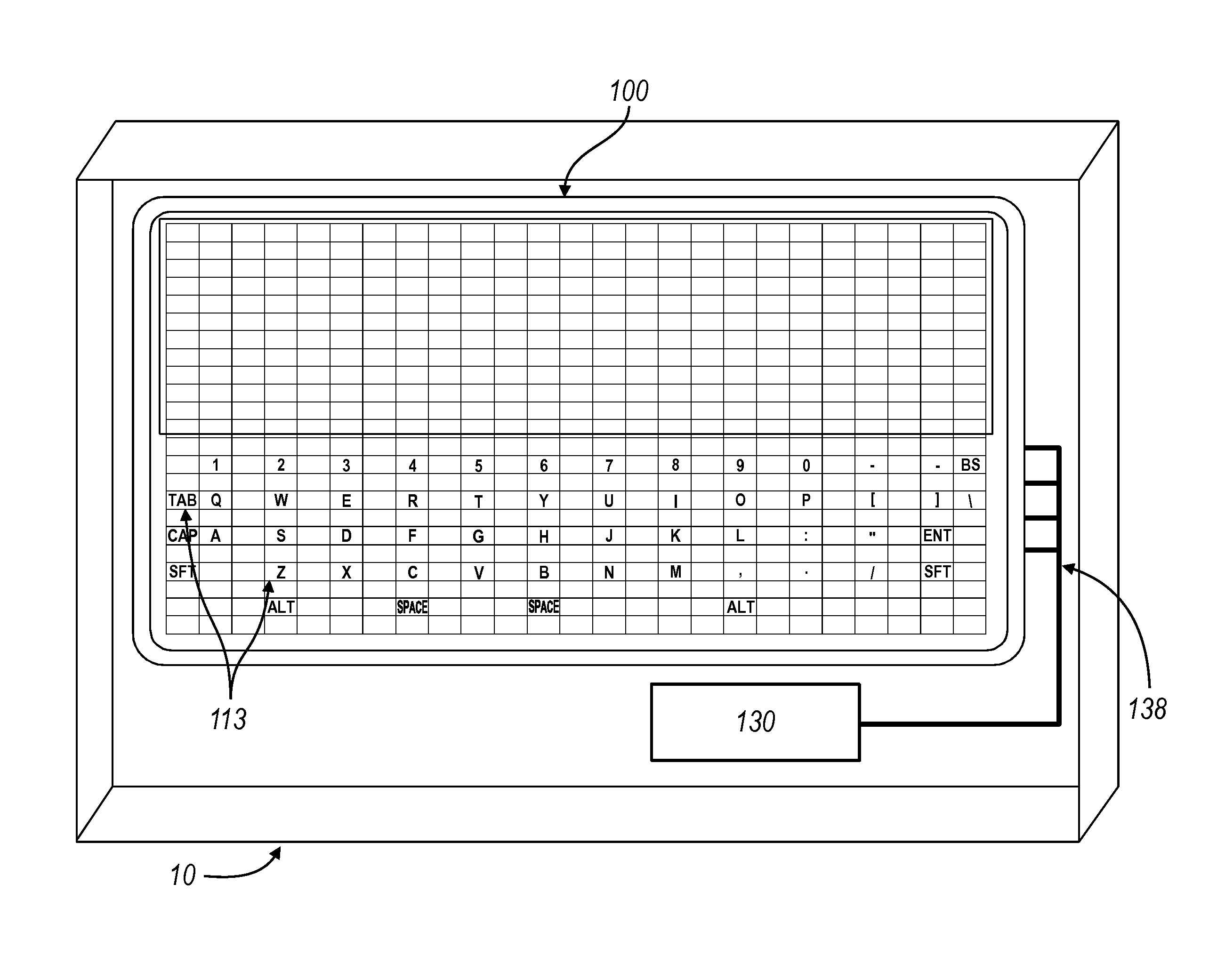
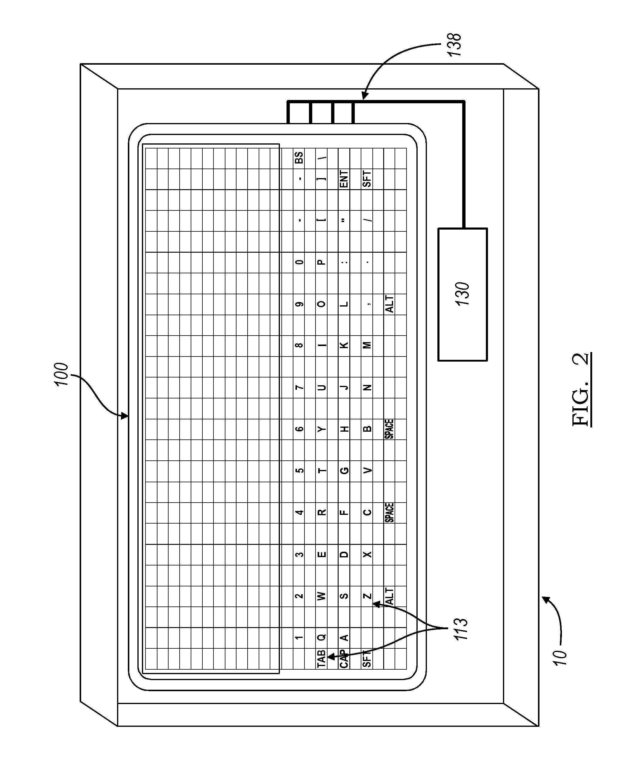
FIG. 2 is a top view of the user interface system of a preferred embodiment applied to a device.
FIGS. 3a and 3b are cross-sectional views of the tactile interface layer of a first and second variation, respectively.
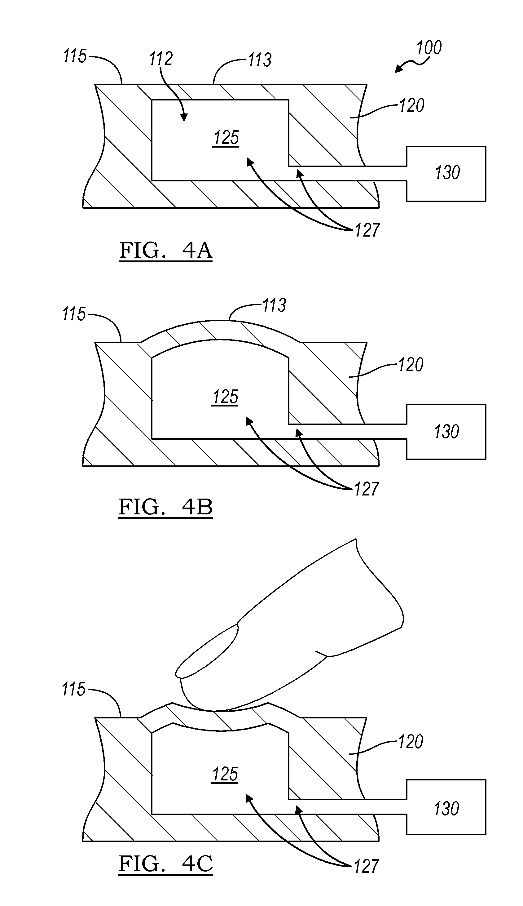
FIGS. 4a, 4b, and 4c are cross-sectional views illustrating the operation of a particular region of the surface of the tactile interface layer in accordance to the preferred embodiments.
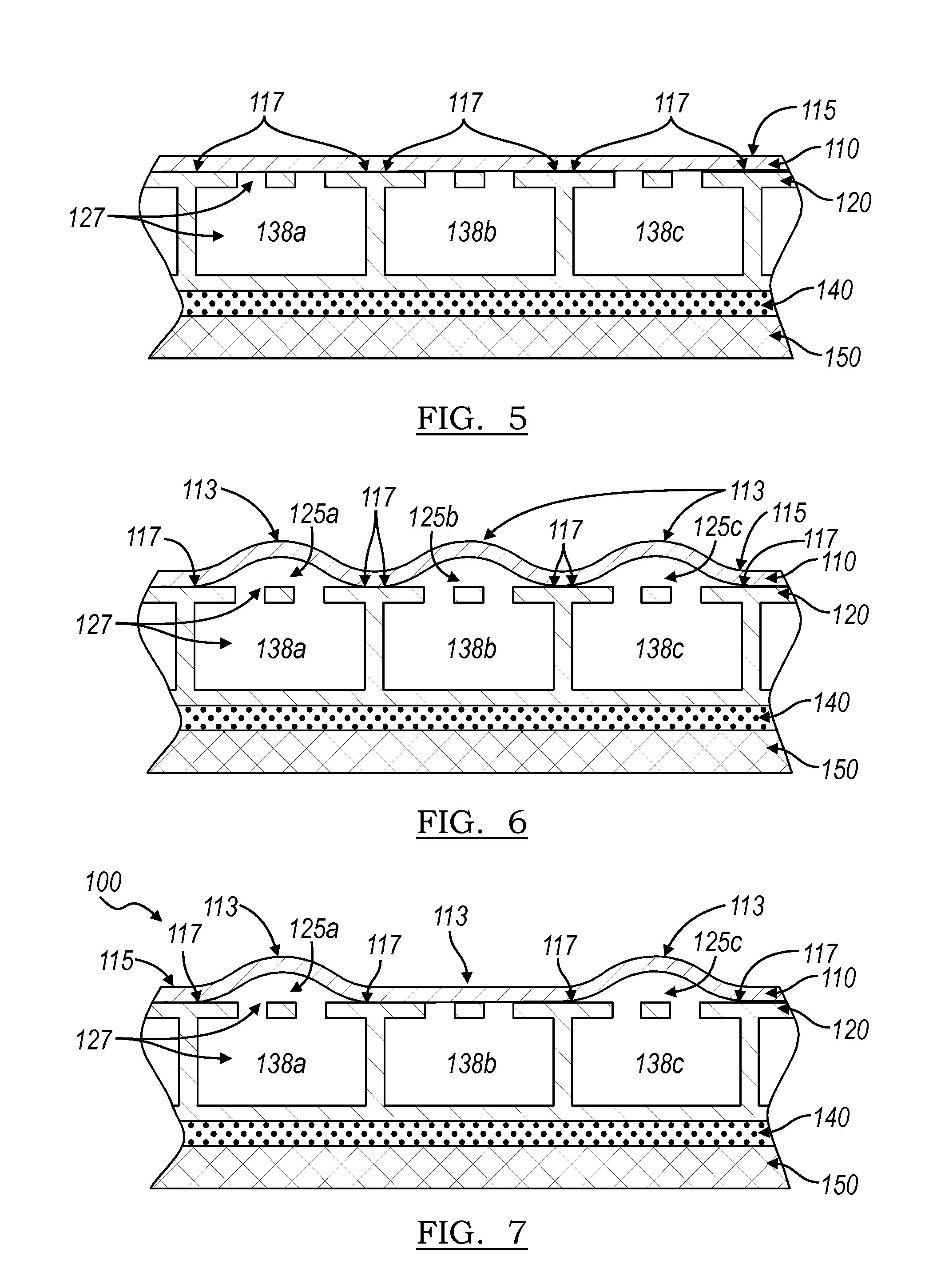
FIG. 5 is a schematic representation of a multi-channel variation of the tactile interface layer with undeformed particular regions of the surface.
FIG. 6 is a schematic representation of a first type and a second type of tactilely distinguishable formation of a first variation.
FIG. 7 is a schematic representation of a first type and a second type of tactilely distinguishable formation of a second variation.
DESCRIPTION OF THE PREFERRED EMBODIMENTS
The following description of the preferred embodiments of the invention is not intended to limit the invention to these preferred embodiments, but rather to enable any person skilled in the art to make and use this invention.
As shown in FIGS. 1 and 2, the method S100 of the preferred embodiments for adjusting a user interface for a device preferably includes providing a user interface to retrieve a user input Step S110, providing a tactile interface layer that defines a surface and includes a volume of fluid and a displacement device that manipulates the volume of fluid to deform a plurality of particular regions of the surface into tactilely distinguishable formations that each represent a key of a keyboard Step S120, allowing the user to provide text input through the keyboard Step S130, predicting a subsequent key input when a user provides an input through the keyboard Step S140, and manipulating the volume of fluid to deform the plurality of particular regions into one of at least two types of tactilely distinguishable formations: a first type for tactilely distinguishable formations that correspond to a predicted key input and a second type for tactilely distinguishable formations that correspond to an unpredicted key input Step S150.
As shown in FIG. 1, after a user provides an input, a particular region that corresponds to a previously predicted key and is deformed into the first type of tactilely distinguishable formation may be transitioned into the second type of tactilely distinguishable formation (as shown for the middle particular region in FIG. 1) when the key corresponding to the particular region is an unpredicted key, providing the user with a substantially detectible tactile difference between a predicted key and an unpredicted key. Similarly, a particular region that corresponds to a previously unpredicted key and is deformed into the second type of tactilely distinguishable formation may be transitioned into the first type of tactilely distinguishable formation when the key corresponding to the particular region is a predicted key. By providing keys that are of two types of tactilely distinguishable formations based on the predicted subsequent input determined in Step S140, additional tactile assistance for text and/or number input is provided to the user. For example, the user may provide an input of the letter "t." The predicted subsequent key inputs may include the letters "h," "e," and/or "r," and an unpredicted key may include the letters "y," "d," and/or "q." The step of manipulating the volume of fluid to deform the plurality of particular regions S150 may include decreasing the height of the unpredicted letters "y," "d," and "q" while maintaining the height of the letters "h," "e," and "r." As a result, the user can tactilely distinguish between a predicted letter and an unpredicted letter. In this particular example, it may be particularly useful to tactilely distinguish between the letter "y" and the letter "h" because of their proximity on a typical QWERTY keyboard, facilitating the user in correctly inputting the letter "h" if desired as opposed to incorrectly inputting the letter "y." Additionally, because the "h" is now tactilely distinguishable from "y," a user may more accurately locate the letter "h" as opposed to the letter "y" without looking, for example, by determining the relative location of the desired key within the overall layout of the keyboard and subsequently feeling for the tactilely distinguishable formation in the determined location. The step of manipulating the volume of fluid to deform the plurality of particular regions S150 preferably manipulates the volume of fluid to deform the plurality of particular regions S150 if the predicted letters are not otherwise distinguishable from the unpredicted letters. For example, a predicted letter "F" may already have a distinguishable feature from, for example, an unpredicted letter "H," such as the nub as seen in typical keyboards and thus fluid may not be further manipulated to provide another distinguishable feature to the letter "F." However, any other suitable arrangement of the manipulation of fluid in Step S150 may be used.
As described above, the keyboard may be a letter keyboard that facilitates text input on a device 10, as shown in FIG. 2. However, the keyboard may alternatively be a number keypad, navigational arrows, directional input, volume input, playback control input, or any other suitable type of keyboard. For example, the keyboard may be a number keypad for a phone application. The step of predicting a subsequent key input S140 may include predicting a subsequent number input, such as in a "speed dial" application. In a second example, each key in the keyboard may represent a word or a phrase or any other suitable combination of letters, numbers, symbols, or any others suitable type of text unit. In this example, the step of predicting a subsequent key input Step S140 preferably includes predicting a subsequent word, phrase, or any other suitable combination of letters, numbers, symbols, and/or any other suitable type of text unit. A particularly notable example of such an input may include Chinese and Japanese text input where a key might represent a subsequent character or combination of characters. The step of manipulating the volume of fluid S150 may include deforming a particular region corresponding to a number associated with a stored speed dial number into the first type of tactilely distinguishable formation and deforming a particular region corresponding to a number that is not associated with a stored speed dial number into the second type of tactilely distinguishable formation. In another example, the keyboard may be the interface of a navigation device. The step of predicting a subsequent key input S140 may include predicting a subsequent letter and/or number of an address input based on a stored database of available addresses. This may provide tactile guidance that may facilitate navigational entry while in a vehicle or in any other suitable situation where the user may not be concentrating on the device 10 (for example, the user is operating the vehicle while entering a desired navigational entry). However, any other suitable type of device, predictive function, or keyboard may be used.
1. Providing a Tactile Interface Layer
As shown in FIGS. 2-7, the tactile interface layer 100 provided in Step S120 of the preferred embodiment includes: a layer 110 defining a surface 115, a substrate 120 supporting the layer 110 and at least partially defining a fluid vessel 127, and a displacement device 130 coupled to the fluid vessel 127 that influences the volume of fluid 112 within the fluid vessel 127 to expand and retract at least a portion of the fluid vessel 127, thereby deforming a particular region 113 of the surface 115. The surface 115 is preferably continuous, such that when swiping a finger across the surface 115 a user would not feel any substantial seams or any other type of interruption in the surface 115. Alternatively, the surface 115 may include features that facilitate the user in distinguishing one region from another. The surface 115 is also preferably planar. The surface 115 is preferably arranged in a flat plane, but may alternatively be arranged in a curved plane or on a first plane and then wrapped around to a second plane substantially perpendicular to the first plane, or any other suitable arrangement. The surface 115 may alternatively include lumps, bumps, depressions, textures, or may be a surface of any other suitable type or geometry. The fluid vessel 127 preferably includes a cavity 125 and the displacement device 130 preferably influences the volume of fluid 112 within the cavity 125 to expand and retract the cavity 125. The fluid vessel 127 may alternatively be a channel 138 or a combination of a channel 138 and a cavity 125, as shown in FIG. 3b. As shown in the variation shown in FIG. 3b, the substrate 120 preferably defines a fluid outlet 116 that allows fluid to flow between the channel 138 and the cavity 125 to deform and un-deform a particular region of the surface 113. The variation may also include a plurality of channels 138a, 138b, and 138c within the substrate 120, as shown in FIG. 5. The fluid outlet may be formed into the substrate, for example, the fluid outlet 116 may be a series of bores that are machined into the substrate in between the channel 138 and the cavity 125 (shown in FIG. 3b) or an open orifice between the cavity 125 and the channel 138 (shown in FIG. 3a), but may alternatively be a property of the material, for example, the substrate 120 may include a porous material that includes a series of interconnected cavities that allow fluid to flow through the substrate 120. The substrate 120 may define any suitable number of fluid outlets 116 that are of any suitable size and shape. The tactile interface layer may also include a fluid outlet layer (not shown) that defines the fluid outlets 116 that is separate from substrate 120 and arranged in between the substrate 120 and layer 110. However, any other suitable arrangement of the fluid outlets 116 may be used. As shown in FIG. 3b, the portion of the substrate 120 (or the fluid outlet layer) that includes the fluid outlets 116 may also function to provide a support for the layer 110 to substantially prevent the layer 110 from substantially depressing into the channel 138 when force is applied over the particular region 113. However, the substrate 120 may be arranged in any other suitable manner and may provide support for the layer 110 in any other suitable way.
The layer 110 is preferably attached to the substrate 120 (or fluid outlet layer) at an attachment point 117 that at least partially defines the size and/or shape of the particular region 113. In other words, the attachment point 117 functions to define a border between a deformable particular region of the surface 113 and the rest of the surface 115 and the size of the particular region 113 is substantially independent of the size of the cavity 124 and/or the channel 138. The attachment point 117 may be a series of continuous points that define an edge, but may alternatively be a series of non-continuous points. The attachment point 117 may be formed using, for example, adhesive, welding, or any other suitable attachment material and/or method. The method and material used to form the attachment point 117 is preferably of a similar optical property as the layer 110 and the substrate 120, but may alternatively be of any other optical property. Other portions of the layer 110 and substrate 120 not corresponding to a particular region of the surface 113 may also be adhered using similar or identical materials and methods to the attachment point 117. Alternatively, the layer 110 and substrate 120 may be left unattached in other portions not corresponding to a particular region of the surface 113. However, the layer 110 and the substrate 120 may be arranged in any other suitable manner.
The fluid vessel 127 may also include a second cavity 125b in addition to a first cavity 125a. When the second cavity 125b is expanded, a second particular region 113 on the surface 115 is preferably deformed. The displacement device 130 preferably influences the volume of fluid 112 within the second cavity 125b independently of the first cavity 125a, but may alternatively influence the volumes of fluid 112 within both the first cavity and second cavity 125a and 125b substantially concurrently. Alternatively, the user interface enhancement system 100 may include a second displacement device 130 that functions to influence the volume of fluid 112 within the second cavity 125b to expand and retract the second cavity 125b, thereby deforming a second particular region 113 of the surface. The second cavity 125b is preferably similar or identical to the cavity 125, but may alternatively be any other suitable kind of cavity. The following examples may be described as expanding a fluid vessel 127 that includes a cavity 125 and a channel 138, but the fluid vessel 127 may be any other suitable combination of combination of cavity 125 and/or channel 138. The tactile interface layer 100 may also include a display 150 coupled to the substrate 120 and adapted to output images to the user. As described above, the tactile interface layer 100 may also include a sensor 140 that functions to detect inputs from the user. The sensor 140 may be a capacitive sensor, a pressure sensor, a touch sensitive display, or any other suitable sensor type that detects the presence of a user input. The sensor 140 may be located within the fluid vessel 127, substantially adjacent to the fluid vessel 127 (as shown in FIGS. 3a and 3b), remote from the fluid vessel 127, remote from a cavity 125 but fluidly coupled to the fluid vessel 127, or in any other suitable location.
The tactile interface layer 100 of the preferred embodiments has been specifically designed to be used as the user interface for an electronic device 10, more preferably in an electronic device 10 that benefits from an adaptive user interface. The electronic device 10 may or may not include a display and/or a touch sensor, for example, an automotive console, a steering wheel, a desktop computer, a laptop computer, a tablet computer, a television, a radio, a desk phone, a mobile phone, a PDA, a personal navigation device, a personal media player, a camera, a watch, a remote control, a mouse, a trackpad, or a keyboard. The tactile interface layer 100 may, however, be used as the user interface for any suitable device 10 that interfaces with a user in a tactile and/or visual manner. The tactile interface layer 100 is preferably integrated with the device, for example, in the variation wherein the tactile interface layer 100 includes a sensor 140, the tactile interface layer 100 is preferably assembled into the device 10 and presented to the user as one unit. Alternatively, the tactile interface layer 100 may function as an accessory to a device 10, the user may be presented the tactile interface layer 100 and the device 10 as two separate units wherein, when coupled to each other, the tactile interface layer 100 functions to provide tactile guidance to the user and/or to receive user inputs. However, any other suitable arrangement of the tactile interface layer 100 may be used.
As shown in FIG. 4, the surface 115 of the tactile interface layer 100 preferably remains flat until tactile guidance is to be provided to the user at the location of the particular region 113. The displacement device 130 then preferably expands the cavity 125 to expand the particular region 113 outward, forming a deformation that may be felt by a user (referenced throughout this document as a "tactilely distinguishable formation"), and providing tactile guidance for the user. The expanded particular region 113 preferably also provides tactile feedback to the user when they apply force onto the particular region 113 to provide input. Alternatively, the displacement device 130 may retract the cavity 125 to deform the particular region 113 inward. However, any other suitable deformation of the particular region 113 may be used.
As shown in FIG. 4, the cavity 125 of the fluid vessel 127 of the preferred embodiment functions to hold a volume of fluid 112 and to have at least two volumetric settings: a retracted volume setting (shown in FIG. 4a) and an extended (or "deformed") volume setting (shown in FIG. 4b). Additionally, there may be a plurality of volume settings or a dynamic range of volume settings. As the user provides an input in Step S130, the extended or deformed particular region of the surface is inwardly deformed (shown in FIG. 4c). The fluid 112 is preferably a substantially incompressible fluid, but may alternatively be a compressible fluid. The fluid 112 is preferably a liquid (such as water, oil, glycerin, or ethylene glycol), but may alternatively be a gas (such as air, nitrogen, or argon) or any other substance (such as a gel or aerogel) that expands the cavity 125 and deforms the surface 115. In the extended volume setting, the cavity 125 deforms the particular region 113 of the surface 115 above the plane of the other regions of the surface 115. When used with a mobile phone device, the deformation of the particular region 113 preferably has a diameter of 2-10 mM and the cavity 125 may be of a substantially equal diameter as the deformation of the particular region 113 or may be of a smaller or larger diameter. When used with this or other applications, however, the cavity 125 may have any suitable dimension.
The displacement device 130 of the preferred embodiment functions to influence the volume of the fluid 112 with the fluid vessel 127 to expand and retract at least a portion of the fluid vessel 127, thereby deforming a particular region 113 (and/or a second particular region 113) of the surface 115. When used with a mobile phone device, the displacement device 130 preferably increases the volume of the fluid 112 within the fluid vessel 127 by approximately 0.003-0.1 ml to expand the cavity 125 to outwardly deform a particular region 113. When used with this or other applications, however, the volume of the fluid may be increased (or possibly decreased) by any suitable amount. The displacement device 130 preferably modifies the volume of the fluid 112 by (1) modifying the volume of the existing fluid 112 in the fluid vessel 127, or (2) adding and removing fluid 112 to and from the fluid vessel 127. The displacement device 130 may, however, influence the volume of the fluid 112 by any suitable device or method. Modifying the volume of the existing fluid 112 in the fluid vessel 127 most likely has an advantage of lesser complexity, while adding and removing fluid 112 to and from the fluid vessel 127 most likely has an advantage of maintaining the deformation of the surface 115 without the need for additional energy (if valves or other lockable mechanisms are used). Although the cause of the deformation of a particular region 113 of the surface 115 has been described as a modification of the volume of the fluid in the fluid vessel 127, it is possible to describe the cause of the deformation as an increase or decrease in the pressure below the surface 115 relative to the pressure above the surface 115. When used with a mobile phone device, an increase of approximately 0.1-10.0 psi between the pressure below the layer 110 relative to the pressure above the layer no, is preferably enough to outwardly deform a particular region 113 of the surface 115. When used with this or other applications, however, the modification of the pressure may be increased (or possibly decreased) by any suitable amount.
The shape of the deformation of the particular region 113 is preferably one that is felt by a user through their finger and preferably acts as (i) a button that can be pressed by the user, (2) a slider that can be pressed by the user in one location along the slider or that can be swept in a sliding motion along the slider (such as the "click wheel" of the second generation Apple iPod), and/or (3) a pointing stick that can be pressed by the user from multiple directions and/or locations along the surface whereby the user is provided with tactile feedback that distinguishes a first directional touch from a second directional touch and/or a touch in a first location from a touch in a second location (such as the pointing stick trademarked by IBM as the TRACKPOINT and by Synaptics as the TOUCHSTYK, which are both informally known as the "nipple"). The deformation may, however, act as any other suitable device or method that provides suitable tactile guidance and feedback. In the variation including a display 150, the shape of the deformation of the particular region 113 also preferably functions to minimize the optical distortion of the image underneath the deformed particular region 113.
2. Predicting a Subsequent Key Input
The step of predicting a subsequent key input when a user provides an input through the keyboard Step S140 preferably functions to predict the next input that the user desires to provide, allowing the tactile interface layer 100 to adjust the arrangement of the particular regions corresponding to inputs in Step S150 and to provide additional tactile guidance to the user. The step of predicting a subsequent key input S140 may include the step of assigning a rank to each possible input and predicting the subsequent key input with the highest rank. The rank may be assigned based upon the frequency of the possible combinations of the provided input and the subsequent input. For example, in the variation of the tactile interface layer 100 that provides a text keyboard to be used to input English, for an input of the letter "t," the subsequent input of the letter "h" would be assigned a substantially high rank and would be provided as a predicted subsequent key because of the number of possible words that begin with the letters "th." However, any other suitable ranking may be assigned to each possible subsequent key input. Alternatively, the step of predicting a subsequent key input S140 may also include the step of storing historical inputs provided by the user and predicting a subsequent key input based on the historical inputs provided by the user. The step of storing historical inputs may include storing the historical inputs from a plurality of users, for example, the inputs provided onto a particular device by a plurality of users may be stored in a central database that may be referenced by the devices to predict a subsequent key input. However, any other suitable type of historical input may be stored and/or used. This may be particularly useful in allowing the predictive input function to accommodate to individual users and their input habits. For example, in the variation of the tactile interface layer 100 that provides a text keyboard to be used to input English, the popular greeting "Yo" is not a standard English word, and may be misinterpreted by the predictive text function to be the word "You." If the user inputs "Yo" and is provided with a predicted subsequent key of the letter "u" and selects to ignore the prediction, then the step of storing historical inputs provided by the user will store the user's historical input of "Yo" as opposed to "You" and utilize this information in predicting subsequent inputs in the future. The step of storing historical inputs may also include applying and/or adjusting a prediction rank based on the historical input. For example, "You" may still have a higher prediction rank than "Yo," but as the number of occurrences of the user inputting the word "Yo" increases, the prediction rank of "Yo" also increases.
In a second example of the step of predicting a subsequent key input S140, the number of possible combination of words and/or numbers available within a database will decrease as the user inputs additional characters. In a particular application in a navigation device that includes a database of available addresses, as a user inputs a first letter or number, the keys that correspond to a possible subsequent letter or number from the addresses stored within the database may be presented to the user. As a subsequent letter is presented, the number of possible subsequent letter or numbers will decrease as the address is narrowed down from the full database of addresses available in the navigation device. In this example, a subsequent letter may not be assigned a ranking and each available address within the database may be thought of as of having the same ranking. Alternatively, a more frequently visited address may be assigned a higher ranking than a less frequently visited address. Alternatively, an address that is substantially closer in proximity to the location of the user may be assigned a higher ranking than an address that is substantially farther away. However, any other suitable method of predicting a subsequent key input may be used.
3. Manipulating the Volume of Fluid
The step of manipulating the volume of fluid to deform the plurality of particular regions into one of at least two types of tactilely distinguishable formations: a first type for tactilely distinguishable formations that represent a predicted key and a second type for tactilely distinguishable formations that represent an unpredicted key Step S150 functions to change the arrangement of the particular regions 113 of the surface to provide additional tactile guidance to the user in providing input. The first type and second type of tactilely distinguishable formations are preferably distinguishable from each other such that the user can substantially determine a tactilely distinguishable formation of a first type from a second type without looking. The first type and the second type of tactilely distinguishable formations may be distinguishable in one of several variations. In a first variation, the first type of tactilely distinguishable formation is stiffer than the second type of tactilely distinguishable formation. For example, the pressure of the fluid within the cavities 125 corresponding to particular regions that represent unpredicted keys may be of a lower pressure than the fluid within the cavities 125 corresponding to particular regions that represent predicted keys. In a second variation, the first type of tactilely distinguishable formation is of a first shape and the second type of tactilely distinguishable formation is of a second shape. For example, the first type of tactilely distinguishable formation may be of a height that is taller than the second type of tactilely distinguishable formation, as shown in FIG. 6, as the height difference between cavities 125a and 125c and cavity 125b. Alternatively, the height of the second type of tactilely distinguishable formation may be substantially zero relative to the surface, as shown in FIG. 7. In this variation, the second type of tactilely distinguishable formation may be alternatively described as substantially tactilely indistinguishable from the surface 115 and the first type of tactilely distinguishable formation may be alternatively described as substantially tactilely distinguishable from the surface 115. Alternatively, the second variation of the first and second types of tactilely distinguishable formations may include a first type that is of a square shape while a second type that is of a dome shape. Yet alternatively, the second variation of the first and second types of tactilely distinguishable formations may include a first type that is of a first diameter and/or width and a second type that is of a smaller diameter and/or width. The first and second types of tactilely distinguishable formations may also be a combination of the above variations. For example, the first type may be of a first shape and a first height while the second type may be of a second shape and a second height. In a third variation, the first type of tactilely distinguishable formation is deformed in a first sequence and the second type of tactilely distinguishable formation is deformed in a second sequence. For example, the first type of tactilely distinguishable formation may be deformed into a shape in a substantially constant sequence (e.g., the shape of the tactilely distinguishable formation does not change substantially) and the second type of tactilely distinguishable formation may be deformed in a substantially pulsating sequence (e.g., the shape of the tactilely distinguishable formation changes cyclically). However, any other type of deformation sequence may be used. However, any other suitable types of tactilely distinguishable formations may be used to distinguish the first type from the second type.
The transition between the first and second types of tactilely distinguishable formations may also be one of several variations. In a first variation, a particular region that corresponds to a previously predicted key and is deformed into the first type of tactilely distinguishable formation may be transitioned into the second type of tactilely distinguishable formation (as shown for cavity 125b in FIG. 6) when the key corresponding to the particular region is an unpredicted key. In a second variation, a particular region that corresponds to a previously unpredicted key and is deformed into the second type of tactilely distinguishable formation may be transitioned into the first type of tactilely distinguishable formation when the key corresponding to the particular region is a predicted key. The first and second variations may be combined to transition between predicted and unpredicted keys. In a usage scenario, when the keyboard is actuated, the user has not provided an input using the keyboard and, by default, all keys may be a predicted key. As a result, each key of the keyboard is deformed into a tactilely distinguishable formation of the first type. After the user provides a first key input, a subsequent key prediction is made and the previously raised keys that are now unpredicted keys are deformed into the second type of tactilely distinguishable formation. After a second key input is provided by the user, a second subsequent key is predicted and the arrangement of the particular regions is again changed such that previously unpredicted keys in the second type of tactilely distinguishable formation may be transitioned into predicted keys in the first type of tactilely distinguishable formation and previously predicted keys in the first type of tactilely distinguishable formation may be transitioned into unpredicted keys in the second type of tactilely distinguishable formation. The transition of particular regions from the first type to the second type of tactilely distinguishable formations may occur concurrently with the transition of particular regions from the second type to the first type of tactilely distinguishable formations to decrease the time of transition. However, any other timing of the transitions may be used.
In a third variation of transition, each tactilely distinguishable formation may return to an original state (for example, the flat surface 115 as shown in FIG. 5) before re-deforming into the desired first and second types of tactilely distinguishable formations. This may decrease the complexity of the system. For example, the displacement device 130 is first removing fluid from the cavities 125 and then displacing fluid back into the cavities 125 as opposed to removing fluid from some cavities 125 while displacing fluid into other cavities 125. Alternatively, in a fourth variation of transition, particular regions that are to transition from the first type of tactilely distinguishable formation into the second type may be transitioned first and then those particular regions that are to transition from the second type of tactilely distinguishable formation into the first type may be transitioned second (or in reverse order) such that fluid is moving in generally one direction at one time. However, any other transition type may be used.
The actuation of the deformation of each particular region 113 of the surface 115 may include implementation of a fluid network and/or valves, such as that described in U.S. application Ser. No. 12/652,704 filed on 5 Jan. 2010 and entitled "User Interface System," which is incorporated in its entirety by this reference, that allow the cavities 125 to be expanded substantially individually. In a first example, in the variation where the second type of tactilely distinguishable formation is of a smaller volume than the first type of tactilely distinguishable formation, the fluid network may function to displace fluid from those particular regions transitioning from the first type of tactilely distinguishable formation to the second type to those particular regions transitioning from the second type of tactilely distinguishable formation to the first type. Alternatively, in a second example, the fluid network may function to displace fluid from those particular regions transitioning from the first type of tactilely distinguishable formation to the second type to a reservoir and to displace fluid from the reservoir to those particular regions transitioning from the second type of tactilely distinguishable formation to the first type of tactilely distinguishable formation. However, any other suitable type of fluid flow within the tactile interface layer 100 may be used.
4. Variations of the Preferred Embodiments
The method S100 of the preferred embodiments may also include the step of manipulating the device 10 to provide a notification of a first type for a predicted key and a notification of a second type for an unpredicted key S170. Combining the notification provided by the device 10 and the tactile guidance provided by the tactile interface layer 100 may further assist the user in entering their desired input in a potentially faster manner. In a first variation, the step of manipulating the device 10 to provide a notification may include manipulating the device 10 to provide a notification to assist the user in selecting a particular key prior to input. In a first example, the device 10 may include a display 150 and the step of manipulating the device 10 to provide a notification includes manipulating the device to provide a visual guide to the user. In a first example the display 150 may display an image corresponding to each particular region that cooperates with the tactile interface layer 100 to represent a keyboard. The first type of notification may be a brighter image or a first color for a predicted key and a less bright or a second color image for an unpredicted key, thus providing additional visual assistance to the user. Alternatively, in the variation where the first and second types of tactilely distinguishable formations are distinct in diameter and/or width, the corresponding image may emulate the width of the tactilely distinguishable formation. In a second variation, the step of manipulating the device 10 to provide a notification may include manipulating the device to provide a notification when an input is detected. In a first example, the device may include a speaker that produces a sound of a first type when a predicted key is selected and a sound of a second type (for example, less loud) when an unpredicted key is selected. In another example, the device may include a vibration inducer that provides a vibration of a first magnitude when a predicted key is selected and a vibration of a second magnitude (for example, lower magnitude), when an unpredicted key is selected. However, the device 10 may provide any other suitable type of notification.
As a person skilled in the art will recognize from the previous detailed description and from the figures and claims, modifications and changes can be made to the preferred embodiments of the invention without departing from the scope of this invention defined in the following claims.
* * * * *
References
D00000
D00001
D00002
D00003
D00004
D00005
XML
uspto.report is an independent third-party trademark research tool that is not affiliated, endorsed, or sponsored by the United States Patent and Trademark Office (USPTO) or any other governmental organization. The information provided by uspto.report is based on publicly available data at the time of writing and is intended for informational purposes only.
While we strive to provide accurate and up-to-date information, we do not guarantee the accuracy, completeness, reliability, or suitability of the information displayed on this site. The use of this site is at your own risk. Any reliance you place on such information is therefore strictly at your own risk.
All official trademark data, including owner information, should be verified by visiting the official USPTO website at www.uspto.gov. This site is not intended to replace professional legal advice and should not be used as a substitute for consulting with a legal professional who is knowledgeable about trademark law.