Heated or cooled dishwasher safe dishware and drinkware
Alexander December 31, 2
U.S. patent number 8,618,448 [Application Number 13/830,934] was granted by the patent office on 2013-12-31 for heated or cooled dishwasher safe dishware and drinkware. This patent grant is currently assigned to Piatto Technologies, Inc.. The grantee listed for this patent is Piatto Technologies, Inc.. Invention is credited to Clayton Alexander.


View All Diagrams
| United States Patent | 8,618,448 |
| Alexander | December 31, 2013 |
Heated or cooled dishwasher safe dishware and drinkware
Abstract
An actively heated mug or travel mug is provided. The mug or travel mug can include a body that receives a liquid therein and a heating system at least partially disposed in the body. The heating system can include one or more heating elements that heat a surface of the receiving portion of the body and one or more energy storage devices. The mug or travel mug can include a wireless power receiver that wirelessly receives power from a power source and control circuitry configured to charge one or more power storage elements and to control the delivery of electricity from the one or more power storage elements to the one or more heating elements. The mug or travel mug also can have one or more sensors that sense a parameter of the liquid or sense a parameter of the heating system and communicates the sensed information to the control circuitry. The control circuitry can turn on, turn off, and/or operate the heating element to actively heat at least a portion of the body to maintain the liquid in a heated state generally at a user selected temperature setting based at least in part on the sensed parameter information. The mug or travel mug can also be paired with a remote device or mobile electronic device to send or receive communications or commands.
| Inventors: | Alexander; Clayton (Westlake Village, CA) | ||||||||||
|---|---|---|---|---|---|---|---|---|---|---|---|
| Applicant: |
|
||||||||||
| Assignee: | Piatto Technologies, Inc.
(Westlake Village, CA) |
||||||||||
| Family ID: | 45995358 | ||||||||||
| Appl. No.: | 13/830,934 | ||||||||||
| Filed: | March 14, 2013 |
Prior Publication Data
| Document Identifier | Publication Date | |
|---|---|---|
| US 20130200064 A1 | Aug 8, 2013 | |
Related U.S. Patent Documents
| Application Number | Filing Date | Patent Number | Issue Date | ||
|---|---|---|---|---|---|
| 13287967 | Nov 2, 2011 | ||||
| 61409493 | Nov 2, 2010 | ||||
| Current U.S. Class: | 219/432; 219/435; 165/64; 165/58; 165/61; 62/3.7; 62/3.3; 219/441 |
| Current CPC Class: | H02J 50/12 (20160201); A47J 36/2466 (20130101); H02J 7/00302 (20200101); H02J 7/025 (20130101); F25D 31/005 (20130101); A47J 36/2483 (20130101); A47J 39/025 (20130101); A47G 19/2288 (20130101); A47G 19/027 (20130101); F25B 21/04 (20130101); F25D 2331/812 (20130101); F25D 2331/808 (20130101) |
| Current International Class: | A47J 36/24 (20060101); H05B 3/06 (20060101); F25B 21/02 (20060101); F25B 21/04 (20060101); A47G 19/22 (20060101) |
References Cited [Referenced By]
U.S. Patent Documents
| 3622753 | November 1971 | Lax |
| 3678248 | July 1972 | Tricault et al. |
| 3739148 | June 1973 | Ryckman, Jr. |
| 3797563 | March 1974 | Hoffmann et al. |
| 3892945 | July 1975 | Lerner |
| 3931494 | January 1976 | Fisher et al. |
| 4068115 | January 1978 | Mack et al. |
| 4095090 | June 1978 | Pianezza |
| 4134004 | January 1979 | Anderson et al. |
| D296509 | July 1988 | Fuke |
| 4827107 | May 1989 | Peery |
| 4980539 | December 1990 | Walton |
| 4982722 | January 1991 | Wyatt |
| 5042258 | August 1991 | Sundhar |
| 5274215 | December 1993 | Jackson |
| 5497883 | March 1996 | Monetti |
| 5550452 | August 1996 | Shirai et al. |
| 5603858 | February 1997 | Wyatt et al. |
| 5786643 | July 1998 | Wyatt et al. |
| 5842353 | December 1998 | Kuo-Liang |
| 5884006 | March 1999 | Frohlich et al. |
| 5948301 | September 1999 | Liebermann |
| 5959433 | September 1999 | Rohde |
| 6013901 | January 2000 | Lavoie |
| 6072161 | June 2000 | Stein |
| 6108489 | August 2000 | Frohlich et al. |
| 6140614 | October 2000 | Padamsee |
| 6144016 | November 2000 | Garvin |
| 6279470 | August 2001 | Simeray et al. |
| 6281611 | August 2001 | Chen et al. |
| 6314867 | November 2001 | Russell |
| 6320169 | November 2001 | Clothier |
| 6376803 | April 2002 | Klinger |
| 6403928 | June 2002 | Ford |
| 6414278 | July 2002 | Frohlich et al. |
| 6674052 | January 2004 | Luo |
| 6852954 | February 2005 | Liu et al. |
| 6870135 | March 2005 | Hamm et al. |
| 7022946 | April 2006 | Sanoner et al. |
| 7034256 | April 2006 | Phillips |
| 7091455 | August 2006 | Fung |
| 7109445 | September 2006 | Patterson et al. |
| 7193190 | March 2007 | Kissel, Jr. |
| 7276676 | October 2007 | Thompson |
| 7287386 | October 2007 | Upadhye et al. |
| 7414380 | August 2008 | Tang et al. |
| 7571830 | August 2009 | Lin |
| 7683572 | March 2010 | Toya |
| 7948209 | May 2011 | Jung |
| 7997786 | August 2011 | Liu |
| 8055310 | November 2011 | Beart et al. |
| 8280453 | October 2012 | Beart et al. |
| 8400104 | March 2013 | Adamczyk et al. |
| 2001/0023866 | September 2001 | Wang |
| 2002/0175158 | November 2002 | Sanoner et al. |
| 2003/0029862 | February 2003 | Clothier |
| 2004/0004072 | January 2004 | Clothier |
| 2004/0194470 | October 2004 | Upadhye et al. |
| 2005/0045615 | March 2005 | Sanoner et al. |
| 2006/0207442 | September 2006 | Pettersson |
| 2007/0182367 | August 2007 | Partovi |
| 2007/0223895 | September 2007 | Flemm |
| 2007/0279002 | December 2007 | Partovi |
| 2008/0019122 | January 2008 | Kramer |
| 2008/0149624 | June 2008 | Tamura |
| 2008/0213449 | September 2008 | Wisner et al. |
| 2008/0251063 | October 2008 | Palena et al. |
| 2009/0102296 | April 2009 | Greene et al. |
| 2009/0166350 | July 2009 | Ho |
| 2009/0184102 | July 2009 | Parker, Jr. et al. |
| 2010/0000980 | January 2010 | Popescu |
| 2011/0062149 | March 2011 | Driel et al. |
| 2011/0072978 | March 2011 | Popescu |
| 2011/0121660 | May 2011 | Azancot et al. |
| 2011/0152979 | June 2011 | Driscoll et al. |
| 2011/0180527 | July 2011 | Abbott |
| 2011/0259871 | October 2011 | Li |
| 2012/0082766 | April 2012 | Maupin et al. |
| 2012/0090333 | April 2012 | DellaMorte et al. |
| 2012/0103562 | May 2012 | Alexander |
| 2012/0118874 | May 2012 | Williams et al. |
| 2012/0132646 | May 2012 | England et al. |
| 2012/0138597 | June 2012 | Quella et al. |
| 2012/0193999 | August 2012 | Zeine |
| 2012/0235505 | September 2012 | Schatz et al. |
| 2012/0235636 | September 2012 | Partovi |
| 2012/0248095 | October 2012 | Lee et al. |
| 2012/0248096 | October 2012 | Lee et al. |
| 2012/0255946 | October 2012 | Kim et al. |
| 2012/0256585 | October 2012 | Partovi et al. |
| 2012/0258229 | October 2012 | Mindrup |
| 2012/0319500 | December 2012 | Beart et al. |
| 631614 | Aug 1982 | CH | |||
| 201076180 | Jun 2008 | CN | |||
| 201237271 | May 2009 | CN | |||
| 102802294 | May 2012 | CN | |||
| 20314416 | Jan 2004 | DE | |||
| 2763463 | Nov 1998 | FR | |||
| 11-268777 | Oct 1999 | JP | |||
| 2003-299255 | Oct 2003 | JP | |||
| 2006-166522 | Jun 2006 | JP | |||
| 2011-171205 | Sep 2011 | JP | |||
| WO 2008/028329 | Mar 2008 | WO | |||
| WO 2008/065175 | Jun 2008 | WO | |||
| WO 2009/138930 | Nov 2009 | WO | |||
| WO 2012/104665 | Aug 2012 | WO | |||
Other References
|
International Search Report and Written Opinion mailed on Mar. 16, 2012 in PCT/US2011/059014. cited by applicant . Non-final Office Action mailed on Mar. 22, 2012 in U.S. Appl. No. 13/287,967. cited by applicant . Final Office Action mailed on Aug. 27, 2012 in U.S. Appl. No. 13/287,967. cited by applicant . Non-final Office Action mailed on Dec. 11, 2012 in U.S. Appl. No. 13/287,967. cited by applicant . Final Office Action mailed on Mar. 13, 2013 in U.S. Appl. No. 13/287,967. cited by applicant . Final Office Action mailed on Jun. 21, 2013 in U.S. Appl. No. 13/287,967. cited by applicant . International Preliminary Report on Patentability mailed on May 7, 2013 in PCT Application No. PCT/US2011/059014. cited by applicant. |
Primary Examiner: Pelham; Joseph M
Attorney, Agent or Firm: Knobbe Martens Olson & Bear, LLP
Parent Case Text
RELATED APPLICATIONS
This application is a continuation-in-part of U.S. application Ser. No. 13/287,967, filed Nov. 2, 2011, which claims priority under 35 U.S.C. .sctn.119(e) to U.S. Provisional App. No. 61/409,493, filed Nov. 2, 2010, the entire contents of both of which is hereby incorporated by reference and should be considered a part of this specification.
Claims
What is claimed is:
1. An actively heated and cooled mug or travel mug, comprising: a body having a receiving portion for receiving and holding a liquid; and a heating and cooling system, comprising three or more thermoelectric heating and cooling elements electrically isolated from each other and configured to actively heat and cool at least a portion of the receiving portion of the body, one or more power storage elements, a wireless power receiver configured to wirelessly receive power from a power source, control circuitry electrically connected to the wireless power receiver, the control circuitry configured to charge the one or more power storage elements and to control the delivery of electricity from the one or more power storage elements to the heating and cooling elements, and one or more temperature sensors configured to sense a temperature of the liquid in the receiving portion, wherein the control circuitry is configured to operate each of the of heating and cooling elements independently of each other to actively decrease the temperature of the liquid if said temperature is greater than a predetermined drinking temperature, and configured to operate the heating and cooling elements to actively increase the temperature of the liquid if said temperature is lower than the predetermined drinking temperature.
2. The mug or travel mug of claim 1, further comprising one or more ultrasound liquid sensors configured to sense when a liquid is poured into the receiving portion via a change in frequency and to communicate said sensed information of liquid presence to the control circuitry, the control circuitry configured to transmit to the user via a user interface information indicative of the volume of liquid in the receiving portion based on said sensed liquid level.
3. The mug or travel mug of claim 1, wherein the control circuitry is configured to automatically shut off power to the heating and cooling elements when a charge level of the one or more power storage elements falls below a predetermined percentage of an amount corresponding to a full charge.
4. The mug or travel mug of claim 1, further comprising a wireless transmitter or receiver and/or transceiver configured to establish a communication connection with a remote electronic device or mobile electronic device.
5. The mug or travel mug of claim 1, wherein the body of the mug or travel mug is water tight and/or dishwasher safe.
6. The mug or travel mug of claim 1, further comprising an orientation sensor configured to sense an orientation of the body, the control circuitry configured to turn off power to the heating and cooling elements and disable said sensors when the body is tilted by more than a predetermined amount from an upright vertical orientation of the body, where an opening of the mug body is at a top end and a base of the body is at a bottom of the mug or travel mug.
7. The mug or travel mug of claim 1, further comprising a water resistant lid removably coupleable to a portion of the body, the water resistant lid selectively removable to allow access to at least the one or more power storage elements.
8. An actively heated and cooled mug or travel mug, comprising: a body having a receiving portion for receiving and holding a liquid, the body having a vacuum insulated chamber configured to reduce the rate in which heat energy exits the mug or travel mug; and a heating and cooling system, comprising three or more heating and cooling elements electrically isolated from each other and configured to actively heat and cool at least a portion of the receiving portion of the body, one or more power storage elements, a wireless power receiver configured to wirelessly receive power from a power source, and control circuitry electrically connected to the wireless power receiver, the control circuitry configured to control charging of the one or more power storage elements and to control the delivery of electricity from the one or more power storage elements to the heating and cooling elements to maintain a temperature of the liquid generally at a predetermined drinking temperature or within a predetermined drinking temperature range, the control circuitry configured to operate the heating and cooling elements independently of each other.
9. The mug or travel mug of claim 8, further comprising one or more sensors configured to sense a parameter of the liquid and communicate said sensed information to the control circuitry.
10. The mug or travel mug of claim 9, wherein the one or more sensors is a liquid sensor configured to sense the presence of liquid in the receiving portion of the body, the control circuitry configured to turn on power to the heating and cooling elements in response to said sensed presence of the liquid.
11. The mug or travel mug of claim 8, further comprising a wireless transmitter or receiver and/or transceiver configured to establish a communication connection with a remote device or mobile electronic device.
12. The mug or travel mug of claim 8, wherein the body of the mug or travel mug is water tight and/or dishwasher safe.
13. The mug or travel mug of claim 8, further comprising an orientation sensor configured to sense an orientation of the body, the control circuitry configured to turn off power to the heating and cooling elements and disable one or more sensors when the body is tilted by more than a predetermined amount from an upright vertical orientation of the body where an opening of the body is at a top end and a base of the body is at a bottom of the mug or travel mug.
14. The mug or travel mug of claim 8, wherein the one or more power storage elements comprise a battery pack removably coupleable to the dishwasher safe body.
Description
BACKGROUND
1. Field
The invention is directed to dishwasher safe dishware and drinkware, such as plates and mugs, and more particularly to actively heated or cooled dishwasher safe dishware and drinkware.
2. Description of the Related Art
Dishware (e.g., plates, bowls), serverware (e.g., platters, serving dishes, hot plates) and drinkware (e.g., cups, mugs, travel mugs, liquid containers, baby bottles, drinking bottles) are sometimes made of ceramic materials. Plates are sometimes heated by placing into an oven, so that the food on the plate can be maintained warm for a longer time than if the plate was not heated. For example, in some restaurants, plates will be heated prior to food being placed thereon, or simultaneously with the food (e.g., a steak) thereon. For example, a plate holding a steak can be placed into an oven to cook the steak, and once removed the plate maintains the food warm for a while. In some instances, a plate or bowl might also be chilled to maintain food thereon cold for a longer period of time (e.g., salad, gazpacho) than if the plate was not chilled. However, such heating and cooling mechanisms are passive mechanisms that rely on the release of heat, in the case of a heated plate, or the absorption of heat, in the case of a chilled plate, by the plate based on the heat transfer properties of the ceramic material.
However, technology for actively heating, or cooling, dishwasher safe dishware or drinkware is not readily available. Accordingly, there is a need for dishwasher safe dishware (e.g., plates, bowls), serverware (e.g., platters, serving dishes, hot plates) and drinkware (e.g., cups, mugs, mugs, travel mugs, liquid containers, baby bottles, drinking bottles) that can be actively heated or cooled during use.
SUMMARY
In accordance with one embodiment, an actively heated mug or travel mug is provided. The actively heated mug or travel mug comprises a body having a receiving portion for receiving and holding a liquid and a heating system. The heating system comprises one or more heating elements configured to heat one or more surfaces of the receiving portion of the body, one or more power storage elements, and a wireless power receiver configured to wirelessly receive power from a power source. The heating system further comprises control circuitry electrically connected to the wireless power receiver, the control circuitry configured to charge the one or more power storage elements and to control the delivery of electricity from the one or more power storage elements to the one or more heating elements. The heating system further comprises one or more sensors configured to sense a parameter of the liquid and/or sense a parameter of the heating system and communicate said sensed parameter information to the control circuitry. The control circuitry is configured to turn on, turn off, and/or operate the one or more heating elements at a given power setting based at least in part on the sensed parameter information.
In accordance with another embodiment, an actively heated mug or travel mug is provided. The actively heated mug or travel mug comprises a body having a receiving portion for receiving and holding a liquid, the body having a vacuum insulated chamber configured to reduce the rate in which heat energy exits the mug or travel mug, and a heating system. The heating system comprises one or more heating elements configured to heat one or more surfaces of the receiving portion of the body, one or more power storage elements, and a wireless power receiver configured to wirelessly receive power from a power source. The heating system further comprises control circuitry electrically connected to the wireless power receiver, the control circuitry configured to charge one or more power storage elements and to control the delivery of electricity from the one or more power storage elements to the one or more heating elements.
In accordance with another embodiment, an actively heated mug or travel mug is provided. The actively heated mug or travel mug comprises a body having a receiving portion for receiving and holding a liquid, and a heating system. The heating system comprises one or more heating elements configured to heat one or more surfaces of the receiving portion of the body, one or more heating elements configured to heat one or more surfaces of the receiving portion of the body, and control circuitry electrically connected to the wireless power receiver, the control circuitry configured to charge one or more power storage elements and to control the delivery of electricity from the one or more power storage elements to the one or more heating elements. The actively heated mug or travel mug further comprises a user interface on a surface of the body, the user interface being electrically connected to the control circuitry and having one or more user actuatable controls to provide operating instructions to the control circuitry. The control circuitry is configured to operate the one or more heating elements to actively heat at least a portion of the body to maintain the liquid in a heated state generally at a user selected temperature setting based at least in part on said instructions.
In accordance with another embodiment, an actively heated mug or travel mug is provided. The actively heated mug or travel mug comprises a body having a receiving portion for receiving and holding a liquid, and a heating system. The heating system comprises one or more heating elements configured to heat one or more surfaces of the receiving portion of the body, one or more power storage elements, a wireless power receiver configured to wirelessly receive power from a power source, and control circuitry electrically connected to the wireless power receiver, the control circuitry configured to charge one or more power storage elements and to control the delivery of electricity from the one or more power storage elements to the one or more heating elements. The heating system further comprises a wireless transmitter or receiver and/or transceiver configured to establish a communication connection with a remote device or mobile electronic device.
BRIEF DESCRIPTION OF THE DRAWINGS
FIG. 1 is a schematic cross-sectional side view of one embodiment of a heated or cooled plate.
FIG. 2 is a schematic exploded view of the heated or cooled plate of FIG. 1.
FIG. 3 is a schematic cross-sectional side view of the heated or cooled plate of FIG. 1 and a charging base for the plate.
FIG. 3A is a schematic perspective bottom view of another embodiment of a heated or cooled plate that is similar to the plate of FIG. 1.
FIG. 3B is a schematic perspective top view of the heated or cooled plate of FIG. 3A and a charging base for the plate.
FIG. 4 is a schematic perspective view of a charging stand for storing multiple heated or cooled plates, and a plurality of heated or cooled plates stored on the stand.
FIG. 5 is a schematic perspective view of the charging stand of FIG. 5.
FIG. 6 is a schematic perspective top view of another embodiment of a heated or cooled plate.
FIG. 7 is a schematic cross-sectional view of another embodiment of a heated or cooled plate.
FIG. 8 is a schematic cross-sectional side view of one embodiment of a heated or cooled mug and its charging base.
FIG. 9 is a schematic exploded view of the heated or cooled mug in FIG. 8
FIG. 9A is a schematic exploded view of another embodiment of a heated or cooled mug.
FIG. 10 is a schematic perspective cross-sectional view of one embodiment of a heated or cooled travel mug.
FIG. 11 is a schematic perspective exploded view of the heated or cooled travel mug of FIG. 10.
FIG. 12 is a schematic perspective view of the heated or cooled travel mug of FIG. 12 and its associated charging base.
FIG. 13 is a schematic perspective cross-sectional view of another embodiment of a heated or cooled travel mug.
FIG. 14 is a schematic perspective cross-sectional view of another embodiment of a heated or cooled travel mug.
FIG. 15 is a schematic perspective view of the heated or cooled travel mug of FIG. 14.
FIG. 16 is a schematic perspective view of another embodiment of a heated or cooled plate, bowl or serving dish.
FIG. 17 is a schematic perspective view of another embodiment of a heated or cooled plate, bowl or serving dish.
FIG. 18 is a schematic perspective view of another embodiment of a heated or cooled plate, bowl or serving dish.
FIG. 19 is a schematic perspective view of one embodiment of a wand for use with a heated or cooled plate, bowl, serving dish, mug, cup, travel mug or liquid container.
FIG. 20 is a schematic perspective view of another embodiment of a heated or cooled plate, bowl or serving dish.
FIG. 21 is a schematic perspective view of one embodiment of a charging station for use with one or more plates, bowls or serving dishes.
FIG. 22 is a schematic front view of the charging station in FIG. 21.
FIG. 23 is a schematic perspective view of the charging station of FIG. 21 holding a plurality of plates, bowls or serving dishes.
FIG. 24 is a schematic perspective view of the charting station of FIG. 23 with one of the plates, bowls or serving dishes shown dismounted from the charging station.
FIG. 25 is a schematic exploded view of one embodiment of a hot or cooled plate.
FIG. 26 is a schematic cross-sectional assembled view of the hot or cooled plate of FIG. 25.
FIG. 27 is a schematic perspective exploded view of another embodiment of a heated or cooled plate, bowl or serving dish.
FIG. 28 is a schematic bottom perspective exploded view of the heated or cooled plate, bowl or serving dish of FIG. 27.
FIG. 29 is a schematic perspective exploded view of another embodiment of a heated or cooled plate, bowl or serving dish.
FIG. 30 is a schematic bottom perspective exploded view of the heated or cooled plate, bowl or serving dish of FIG. 29.
FIG. 31 is a schematic exploded view of one embodiment of a heated or cooled baby bottle liquid container.
FIG. 32 is a schematic cross-sectional assembled view of the heated or cooled baby bottle of FIG. 31.
FIG. 33 is a box diagram of one method of operating a heated or cooled plate, bowl, serving dish, mug, cup, travel mug or liquid container.
DETAILED DESCRIPTION
FIGS. 1-3 show one embodiment of heated or cooled dishware or serverware. In particular, FIGS. 1-3 show one embodiment of a heated or cooled plate 100, bowl or serving dish. In the illustrated embodiment, the plate 100, bowl or serving dish has a circumferential wall 10 with a side surface 30a and a base 20 having a top surface 20a, where the side surface 30a and top surface 20a define a recess 30 that can hold food (e.g., receiving portion of the plate that holds food). In another embodiment, the plate 100, bowl or serving dish can be flat with a generally flat top surface (e.g., where the food receiving portion is not recessed). The wall 10 extends from a top edge 12 to a bottom edge 14. A bottom portion 40 of the plate 100, bowl or serving dish defines a bottom surface 42 of the plate 100, bowl or serving dish, which is recessed relative to the edge 14 and defines a recess 16 of the plate 100, bowl or serving dish, such that the edge 14, not the bottom surface 42, contacts a table or counter surface when the plate 100, bowl or serving dish is placed on the table or counter surface. In another embodiment, the bottom surface 42 can be flush with the bottom edge 14, not recessed relative to the edge 14. In still another embodiment, the bottom surface 42 can protrude from the bottom of the plate 100, bowl or serving dish relative to the edge 14. The plate 100, bowl or serving dish can look (e.g., be sized and shaped) like a conventional plate and fit within standard dishwasher racks.
With continued reference to FIG. 1, the bottom portion 40 attaches to the wall 10 so that a cavity 50 is defined between the bottom portion 40 and the base 20, where the cavity 50 is sized to house several components, as described below. As shown in FIG. 2, the plate 100, bowl or serving dish can include a heating or cooling system 55, which can include a heating or cooling element 60, an insulative member 70, one or more electrical energy storage devices 80 electrically connected to the heating of cooling element 60, and an electronic module 90. The heating or cooling element 60, insulative member 70, electrical energy storage devices 80 and electronic module 90 can be disposed (e.g., embedded) in a bottom section of the plate 100, bowl or serving dish. In another embodiment, the heating or cooling system 55 can be housed in a module that is removably attachable to the plate 100, bowl or serving dish. In this embodiment, the heating or cooling element 60 and insulating member 70 can be a part of the removable module or can be disposed in the plate, and not part of the removable module.
In one embodiment, the heating or cooling element 60 can be heater or heating wire that is disposed adjacent a bottom surface 20b of the base 20 (e.g., adhered or otherwise secured to the bottom surface 20b), where the heater wire can heat up and transfer heat to the top surface 20a of the base 20 via conduction through the base 20 (e.g., to raise the temperature of the base 20 above ambient temperature to maintain food on the plate 100, bowl or serving dish warm, such as at a desired temperature or within a desired temperature range). In one embodiment, the heating or cooling system 55 can include a drive transistor to accommodate heavy switching current flowing from the electrical energy storage element 80 to one or more low resistance heating or cooling element 60. The insulative member 70 can be plate-like and disposed proximate the heating or cooling element 60 so that the heating or cooling element 60 is interposed between the insulative member 70 and the base 20. In one embodiment, the insulative member 70 can be a ceramic plate. However, in other embodiments, the insulative member 70 can be made of other suitable materials that are thermally insulative. In still other embodiments, the insulative member 70 can be excluded.
With continued reference to FIG. 2, the one or more energy storage devices 80 can in one embodiment be batteries, such as rechargeable batteries. For example, the one or more energy storage devices 80 can be lithium-ion (Li-ion) batteries or lithium polymer (Li-poly) batteries. However, in other embodiments where the energy storage devices 80 are batteries, the batteries can be other suitable types (e.g., lead acid, nickel cadmium, nickel metal hydride). In one embodiment, the battery can be provided in combination with a step-up transformer to provide the required voltage. In another embodiment, the one or more energy storage devices 80 can be capacitors. The one or more energy storage devices 80 can be electrically connected to the heating or cooling element 60 and configured to supply power to the heating or cooling element 60 to heat or cool at least a portion of the plate 100, bowl or serving dish.
The electronic module 90 can be attached to a top surface 44 of the bottom portion 40 and electrically connected to the one or more energy storage devices 80. In one embodiment, the electronic module 90 can include one or more of a wireless power receiver 92, control circuitry 94 (e.g., controller circuit, microcontroller, etc.) and a charger 96 (e.g., charging circuit) for charging the one or more energy storage devices 80. In other embodiments, the electronic module 90 can have different or additional electronics. The electronic module 90 can include a MCU with capacitive sensing and graphic control features. In one embodiment, the wireless power receiver 92 is electrically connected to the battery charger 96, which is connected to the one or more energy storage device 80 that are then electrically connected to the heating or cooling element 60 through a controller circuit 94. The control circuitry can also be used to manage the charging of the one or more energy storage devices 80. In another embodiment, where the energy storage devices 80 are excluded (as discussed further below), the wireless power receiver 92 can be electrically connected directly to the heating or cooling element 60. The control circuitry 94 can operate to manage the power delivered to the heating or cooling element 60.
In one embodiment, the bottom portion 40 can be removably attached to the plate 100, bowl or serving dish to allow access to the heating or cooling system 55 in the cavity 50. For example, the bottom portion 40 can be mechanically coupled to the plate 100, bowl or serving dish (e.g., with screws, a threaded interface between the bottom portion 40 and the plate 100, bowl or serving dish, a press-fit connection, etc.). The bottom portion 40 can be removed to allow the replacing of the one or more energy storage devices 80 and the servicing of the heating or cooling system 55. In one embodiment, the bottom portion 40 can be a water resistant lid that can be removably attachable (e.g., threaded on or screwed) to the plate 100, bowl or serving dish for accessing the heating or cooling system 55. In another embodiment, the bottom portion 40 can be a water resistant lid that can be removably attachable (e.g., threaded on or screwed) to the plate 100, bowl or serving dish for accessing the one or more energy storage devices 80. In yet another embodiment, the energy storage devices 80 can be in a pack that is attached (e.g., threaded, snap fit, screwed down) onto the bottom of the plate 100, bowl or serving dish, where the pack's electrical contacts connect with a set of electrical contacts on the bottom of the plate 100, bowl or serving dish, as shown for example in FIGS. 27-28 and described below. In still another embodiment, the one or more energy storage devices 80 can be sealed in the body of the plate 100 and not be removable (e.g., the heating or cooling system 55 and electronics of the plate 100 can be sealed in the plate so as to not be removable). This configuration (e.g., sealed energy storage elements 80 that are not removable) can also be incorporated into any other drinkware, dishware or serverware devices, such as the plate 100', 800, 800', 1100, 1300, 1400, mug 400 and travel mug 600, cup, baby bottle 1500 or liquid container discussed below
With continued reference to FIG. 3, a charging base 200 can have a protruding or raised section 220 with a top surface 222 and a bottom surface 224. A wireless power transmitter 240 can be attached to the bottom surface 224. The protruding section 220 is preferably shaped and sized to at least partially fit into the recess 16 in the plate 100, bowl or serving dish, such that the top surface 222 is adjacent the bottom surface 42 of the bottom portion 40. Advantageously, the protruding section 220 fits at least partially into the recess 16 so as to generally align the electronic module 90 over the wireless power transmitter 240 to facilitate wireless power transmission between the wireless power transmitter 240 and the wireless power receiver 92. In another embodiment, the plate 100, bowl or serving dish can have a protruding portion and the charging base 200 a recessed portion, where the protruding portion fits at least partially within the recessed portion when the plate 100, bowl or serving dish is coupled to the charging base 200. The wireless power transmitter 220 can be electrically connected to a power source (not shown), such as a wall outlet, via a power cord (not shown).
In one embodiment, the wireless power transmitter 240 can be an induction coil and the wireless power receiver 92 can also be an induction coil. Therefore, in one embodiment, the charging base 200 can wirelessly transmit power from the power transmitter 240 to the wireless power receiver 92 via induction coupling. However, transmission of power from the wireless power transmitter 240 to the wireless power receiver 92 is not limited to inductive coupling. In other embodiments, other forms of short-distance wireless energy transfer can be used (e.g., microwave energy). In still other embodiments, further discussed below, long-distance wireless energy transfer can be used to transmit power to the wireless power receiver 92, without the use of a charging base.
In one embodiment, the heating or cooling system 55 is advantageously embedded or housed in the body of the plate 100, bowl or serving dish so that no portion of the heating or cooling system 55 is exposed or can be contacted by a user while holding the plate 100, bowl or serving dish. Therefore, the plate 100, bowl or serving dish can advantageously be exposed to water or other liquids, e.g., in a sink or in a dishwasher, without exposing the heating or cooling system 55 to said water or liquids, thereby inhibiting damage to the heating or cooling system 55. Additionally, by having all components embedded or housed in the body of the plate 100, bowl or serving dish, the plate 100, bowl or serving dish can be aesthetically pleasing as it looks like a conventional plate.
FIGS. 3A-3B shows another embodiment of a heated or cooled plate 100''', bowl or serving dish. The heated or cooled plate 100''', bowl or serving dish is similar to the heated or cooled plate 100, bowl or serving dish and includes the same components and features disclosed for the heated or cooled plate 100, except as noted below. Thus, the reference numerals used to designate the various components of the heated or cooled plate 100''', bowl or serving dish are identical to those used for identifying the corresponding components of the heated or cooled plate 100, bowl or serving dish in FIGS. 1-3, except that a "'''" has been added to the reference numerals.
In another embodiment, shown in FIGS. 3A and 3B, the plate 100''', bowl or serving dish can include one or more corrosion resistant electrical contacts 46''' on an outer surface of the plate 100''', bowl or serving dish, such as the bottom surface 42''' of the bottom portion 40''' of the plate 100'''', bowl or serving dish, where the electrical contacts are sized and shaped to contact corresponding electrical contacts 246''' on the charging base 200''' (e.g., on the top surface 222''' of the protruding section 220''' of the charging base 200'''), when the plate 100''', bowl or serving dish is placed on the charging base 200''' so that power is transmitted from the charging base 200''' to the energy storage devices 80''', heating or cooling element 60''' and/or electronic module 90''' in the plate 100''', bowl or serving dish through the electrical contacts 46''', 246'''. In one embodiment, the electrical contacts of the plate 100''', bowl or serving dish can protrude from a surface of the plate 100''', bowl or serving dish, such as electrical posts. In another embodiment, shown in FIG. 3A, the electrical contacts 46''' of the plate 100''', bowl or serving dish can be one or more contact pads on the bottom surface 42''' of the bottom portion 40''' of the plate 100''', bowl or serving dish, which can contact corresponding contacts, such as the pin contacts 246''') on the top surface 222''' of the charging base 200'''. However, the electrical contacts on the plate 100''', bowl or serving dish and charging base 200''' can have other suitable configurations. As shown in FIGS. 3A and 3B, the pate 100''' can have a slot 48''' on bottom surface of the plate 100''', bowl or serving dish (e.g., formed on the bottom surface 42''' of the bottom portion 40''' of the plate 100''', bowl or serving dish) that is sized and shaped to receive a pin or key 248''' on the charging base 200''. The slot 48''' and pin or key 248''' provide a "clocking" aspect of the plate 100''', bowl or serving dish that allows the electrical contacts 46''' of the plate 100''', bowl or serving dish to readily align with the electrical contacts 246''' of the charging base 200'''. However, in another embodiment, the slot can be formed on the charging base 200''' and the pin or key can be formed on the bottom of the plate 100''', bowl or serving dish. This configuration of electrical contacts and slot/key arrangement can also be incorporated into any other drinkware, dishware or serverware devices, such as the plate 800, 800', 1100, 1300, 1400, mug 400 and travel mug 600, cup, baby bottle 1500 or liquid container discussed below.
In another embodiment, the heating or cooling system 55 can be housed in a non-water proof module that can be removably attached to the plate 100, bowl or serving dish (e.g., threadably coupled to the plate 100, or coupled via a pin/slot assembly where the module twists into the bottom of a plate 100) to heat or cool the plate 100. In this embodiment, when the plate 100, bowl or serving dish is to be washed, the heating or cooling module can be decoupled from the plate 100, bowl or serving dish before the plate 100, bowl or serving dish is washed (e.g., placed in the dish washing machine). The heating or cooling module can then be placed on a corresponding charging station for use at a later time when it can again be coupled to a plate 100, bowl or serving dish to heat or cool food on the plate 100. The embodiment described above can apply to other forms of dishware (e.g., mug, cup, serving dish).
In another embodiment, the charging base 200 can be excluded and power can be transmitted to the wireless power receiver 92 via a remote power transmitter using long-distance wireless energy transmission, as further discussed below. In this embodiment, where the heated or cooled plate 100, bowl or serving dish also does not have energy storage devices, such as the energy storage devices 80, the heating or cooling element 60 is electrically connected to the wireless power receiver 92 via the control circuit 94, which is operable to control the amount of power that is provided to the heating or cooling element 60. During operation, if the plate 100, bowl or serving dish is out of range of the wireless power transmission, the heating or cooling element 60 will lose power and shut off For example, in this embodiment if the plate 100, bowl or serving dish is not on a charging base, such as the charging base 200, or out of the range of power transmission from a remote wireless power transmitter, the heating or cooling element 60 in the plate 100, bowl or serving dish will lose power and shut off.
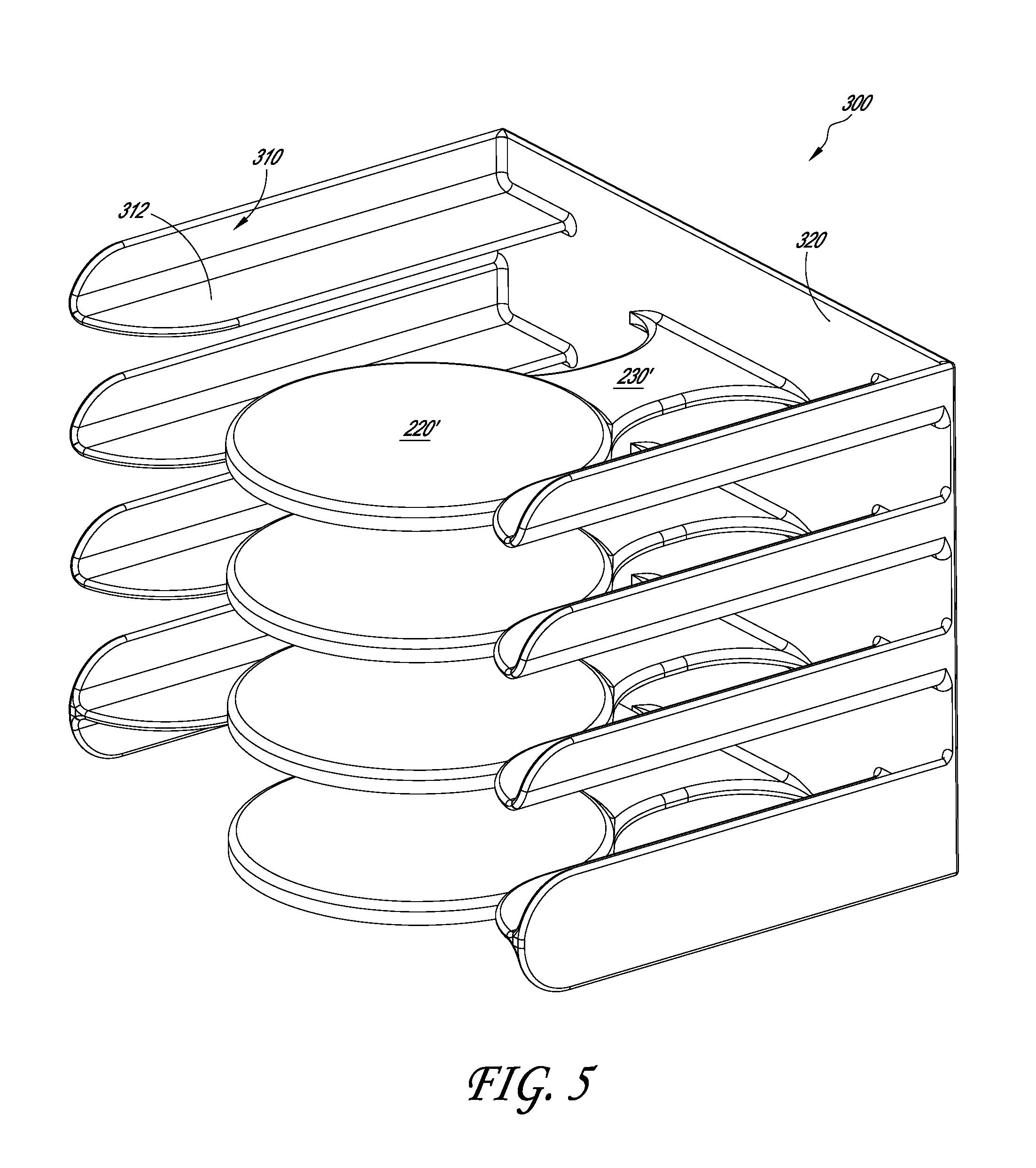
FIGS. 4 and 5 show one embodiment of a charging stand 300 that can be stored in a cabinet, such as a kitchen cabinet, or on a countertop or in a pantry. The charging stand 300 can have a plurality of charging bases 220', each of which is attached to a rear wall 320 of the charging stand 300 by a connecting support 230'. The charging stand 300 can also have a pair of arms 310 on either side of the charging base 220', each arm 310 having a surface 312 that can contact at least a portion of the wall 10 of the plate 100, bowl or serving dish and helps support the plate 100, bowl or serving dish on the charging base 220'. Each of the charging bases 220' can have a wireless power transmitter, such as the wireless power transmitter 240, disposed therein, which can transmit power to a wireless power receiver in the heated or cooled plate 100, bowl or serving dish that is placed on the charging base 220'. The charging stand 300 can have a power cord (not shown) to connect the stand to, for example, a wall outlet, in order to electrically connect the wireless power transmitters in the charging bases 220' with the power source.
In another embodiment, the charging stand 300 can be excluded, and the plates 100 can be stacked on top of each other, with a single charging base at the bottom of the stack (e.g., the charging base 200 in FIG. 3) In this embodiment, the electronic module 90 in each plate 100, bowl or serving dish can include a repeater circuit that takes the power coming in from the wireless power receiver 92 (inside the plate 100) and then energizes a wireless power transmitter (not shown) which would be mounted just underneath bottom surface 20b inside the same plate 100. In this embodiment, when another plate is stacked on top of this plate 100, the top plate can receive power from the wireless power transmitter which is located in the plate 100, bowl or serving dish directly beneath it. In this manner, when a number of plates were stacked on top of each other, each plate would wirelessly receive power from the plate beneath it, and transmit power to the plate above it. In one embodiment, the energy storage devices are excluded from the plate 100, bowl or serving dish (or mug 400 or travel mug 600, cup or liquid container discussed below), so the wireless power receiver can be electrically connected to the heating or cooling element. This allows a stack of plates 100 to be positioned on one stand.
FIG. 6 shows another embodiment of a heated or cooled plate 100'. The heated or cooled plate 100', bowl or serving dish is similar to the heated or cooled plate 100, bowl or serving dish and includes the same components and features disclosed for the heated or cooled plate 100, except as noted below. Thus, the reference numerals used to designate the various components of the heated or cooled plate 100', bowl or serving dish are identical to those used for identifying the corresponding components of the heated or cooled plate 100, bowl or serving dish in FIGS. 1-3, except that a "'" has been added to the reference numerals.
In the illustrated embodiment, the heated or cooled plate 100', bowl or serving dish has a heating or cooling element 60' that includes a trace pattern that is traced or laid onto at least a portion of the top surface 20a' of the base 20' of the plate 100'. For example, the trace pattern can be screen printed onto the top surface 20a' and have a connecting portion (not shown) that electrically connects the heating or cooling element 60' to the energy, storage devices 80, wireless power receiver 92, and/or control circuitry 94. This configuration of heating or cooling element can also be incorporated into any other drinkware, dishware or serverware devices, such as the plate 800, 800', 1100, 1300, 1400, mug 400 and travel mug 600, cup, baby bottle 1500 or liquid container discussed below.
FIG. 7 shows another embodiment of a heated or cooled plate 100''. The heated or cooled plate 100'', bowl or serving dish is similar to the heated or cooled plate 100, bowl or serving dish and includes the same components and features disclosed for the heated or cooled plate 100, except as noted below. Thus, the reference numerals used to designate the various components of the heated plate 100'', bowl or serving dish are identical to those used for identifying the corresponding components of the heated plate 100, bowl or serving dish in FIGS. 1-3, except that a "''" has been added to the reference numerals.
In the illustrated embodiment, the cavity 50'' in the heated or cooled plate 100'', bowl or serving dish can be subdivided by the insulative member 70 into a first cavity 50a between the bottom portion 40 and the insulative member 70 and a second cavity 50b between the insulative member 70 and the base 20. The energy storage devices 80 and electronic module 90 are disposed in the first cavity 50a. The insulative member 70 is positioned against a ledge 10a defined between the bottom portion 40 and the base 20 so that the insulative member 70 is spaced from the heating or cooling element 60, thereby defining the second cavity 50b. In the illustrated embodiment, the second cavity 50b is under a vacuum, which advantageously further thermally insulates the energy storage devices 80 and electronic module 90 from the heating or cooling element 60. Additionally, having the second cavity 50b under a vacuum advantageously allows the top surface 20a of the base 20 to maintain its temperature for a longer period of time, as the vacuum in the second cavity 50b inhibits heat transfer through the bottom of the plate 100''. In the illustrated embodiment, the heating or cooling element 60 can be electrically connected to the one or more energy storage devices 80 via a connector (not shown) that extends between the first and second cavities 50a, 50b (e.g., a trace line printed on the side wall of the first and second cavities 50a, 50b). This vacuum configuration can also be incorporated into any other drinkware, dishware or serverware devices, such as the plate 800, 800', 1100, 1300, 1400, mug 400 and travel mug 600, cup, baby bottle 1500 or liquid container discussed below.
FIGS. 8-9 illustrate a heated or cooled mug 400, cup or liquid container with a circumferential wall 412 having a side surface 412a, a handle 414 and a base 420 having a top surface 420a, where the side surface 412a and top surface 420a define a cavity 418 that can hold a liquid or solid (e.g., coffee, soup, ice cream). The heated or cooled mug 400, cup or liquid container can have a bottom portion 419 that defines a recess 450 between a bottom edge 416a and the base 420. A bottom member (e.g., plate) 440 can be positioned against a ledge 419a of the bottom portion 419, so as to define a cavity 450a between the bottom member 440 and the base 420. In the illustrated embodiment, a heating or cooling system 455 can be disposed (e.g., embedded) in the cavity 450a. The heating or cooling system 455 can include a heating or cooling element 460, an insulative member 470, one or more energy storage devices 480 and an electronic module 490, and these components can be arranged and connected in the same manner described above in connection with the heated or cooled plate 100. In another embodiment, the insulative member 470 can be excluded.
The heating or cooling element 460 can be disposed adjacent a bottom surface 420b of the base 420 so as to conduct heat through the base 420 to a top surface 420a of the base 420. In one embodiment, the heating or cooling element 460 can also be disposed within the wall 412 and behind a side surface 412 of the mug 400, cup or liquid container. In one embodiment, the heating or cooling element 460 can be a heater wire or heating wire. In another embodiment, the heating or cooling element 460 can be a resistive heater. However, in other embodiments, the heating or cooling element 460 can include other suitable mechanisms. In one embodiment, the heating or cooling system 455 can include a drive transistor to accommodate heavy switching current flowing from the electrical energy storage element 480 to one or more low resistance heating or cooling element 460.
The electronic module 490 can be attached to a top surface 444 of the bottom member 440 and include one or more of a wireless power receiver 492, control circuitry 494 (e.g., controller circuit, microcontroller, etc.) and a charger 496 (e.g., charging circuit) for charging the one or more energy storage devices 480. The electronic module 490 can include a MCU with capacitive sensing and graphic control features. The control circuitry 494 can operate to manage the power delivered to the heating or cooling element 460. The control circuitry 494 can also be used to manage the charging of the one or more energy storage devices 480. In one embodiment, the wireless power receiver 492 is electrically connected to the battery charger 496, which is electrically connected to the energy storage devices 480 that in turn are electrically connected to the heating or cooling element 460. In another embodiment, where energy storage devices are excluded (as discussed further below), the wireless power receiver 492 can be electrically connected to the heating or cooling element 460. In one embodiment, the heating or cooling system 455 is completely disposed in the bottom portion 419 so that no part of the system 455 is visible (i.e., the mug 400 looks like a conventional mug). In another embodiment, the heating or cooling system 455 can be housed in a module that is removably attachable to the mug 400.
With continued reference to FIGS. 8-9, the bottom portion 440 can be axially spaced from the bottom edge 416a so as to define a recess 416 at the bottom of the mug 400, cup or liquid container. A charging base 500 for the heated or cooled mug 400, cup or liquid container can include a raised portion 520 with a top surface 522, where the raised portion 520 is sized and shaped to fit at least partially within the recess 416 when the mug 400, cup or liquid container is placed on the charging base 500, so that a bottom surface 442 of the bottom member 440 is adjacent the top surface 522 of the raised portion 520. The charging base can include a wireless power transmitter 540 attached to a bottom surface 524 of the raised portion 520, where the wireless power transmitter 540 is arranged on the bottom surface 524 so as to generally align with the electronic module 490 when the mug 400, cup or liquid container is positioned on the charging base 500 to facilitate wireless power transmission between the wireless power transmitter 540 and the wireless power receiver 492 (e.g., via short distance wireless energy transfer, such as inductive coupling, as discussed above). In another embodiment, the mug 400, cup or liquid container can have a protruding portion at its bottom and the charging base 500 can have a corresponding recessed portion, where the protruding portion fits within the recessed portion when the mug 400, cup or liquid container is coupled to the charging base 500. The wireless power transmitter 540 can be electrically connected to a power source (not shown), such as a wall outlet, via a power cord (not shown).
In one embodiment, the bottom member 440 can be removably attached to the mug 400, cup or liquid container to allow access to the heating or cooling system 455 in the cavity 450a. For example, the bottom member 440 can be mechanically coupled to the mug 400, cup or liquid container (e.g., with screws, a threaded interface between the bottom member 440 and mug 400, a press-fit connection). The bottom member 440 can be removed to allow the replacing of the one or more energy storage devices 480 and the servicing of the heating or cooling system 455. In one embodiment, the bottom member 440 can be a water resistant lid that can be removably attachable (e.g., threaded on or screwed) to the mug 400, cup or liquid container for accessing the heating or cooling system 455. In another embodiment, the bottom member 440 can be a water resistant lid that can be removably attachable (e.g., threaded on or screwed) to the mug 400, cup or liquid container for accessing the one or more energy storage devices 480. In yet another embodiment, the energy storage devices 480 can be in a pack that is attached (e.g., threaded, snap fit, screwed down) onto the bottom of the mug 400, where the pack's electrical contacts connect with a set of electrical contacts on the bottom of the mug 400.
In another embodiment, the charging base 500 can be excluded and power can be transmitted to the wireless power receiver 492 via a remote power transmitter using long-distance wireless energy transmission, as further discussed below. In this embodiment, where the heated or cooled mug 400, cup or liquid container also does not have energy storage devices, such as the energy storage devices 480, the heating or cooling element 460 is electrically connected to the wireless power receiver 492 via the control circuit 494, which is operable to control the amount of power that is provided to the heating or cooling element 460. During operation, if the mug 400, cup or liquid container is out of range of the wireless power transmission, the heating or cooling element 460 will lose power and shut off. For example, in this embodiment if the mug 400, cup or liquid container is not on a charging base, such as the charging base 500, or out of the range of power transmission from a remote wireless power transmitter, the heating or cooling element 460 in the mug 400, cup or liquid container will lose power and shut off.
The one or more energy storage devices 480 can advantageously supply power to the heating or cooling element 460 for a prolonged period of time before its power charge diminishes, thereby advantageously maintaining the contents of the mug 400, cup or liquid container (e.g., soup, coffee, ice cream) hot or cold, for a prolonged period of time. In one embodiment, the energy storage devices 480 can power the heating or cooling element 460 for at least 15 minutes. In another embodiment, the energy storage devices 480 can power the heating or cooling element 460 for between about 30 minutes and about 60 minutes. However, in another embodiment, the energy storage devices 480 can power the heating or cooling element 460 for greater than 60 minutes. In another embodiment, the power level, or desired temperature, can be selected by the user (e.g., via a switch) which will extend or shorten the duration of time that the heating or cooling element 460 will run for, as further discussed below.
As discussed above, in one embodiment, the heating or cooling system 455 is advantageously embedded in the body of the mug 400, cup or liquid container (e.g., embedded in the bottom portion 419 of the mug 400) so that no portion of the heating or cooling system 455 is exposed or can be contacted by a user while holding the mug 400, cup or liquid container. Therefore, the mug 400, cup or liquid container can advantageously be exposed to water or other liquids, e.g., in a sink or in a dishwasher, without exposing the heating or cooling system 455 to said water or liquids, thereby inhibiting damage to the heating or cooling system 455. Additionally, by being embedded in the body of the mug 460, the mug 460 can be aesthetically pleasing as it looks like a conventional mug.
In another embodiment, the heating or cooling system 455 can be housed in a non-water proof module that can be removably attached to the mug 400, cup or liquid container (e.g., threadably coupled to the mug 400, or coupled via a pin/slot assembly where the module twists into the bottom of a mug 400) to heat or cool the mug 400, cup or liquid container. In this embodiment, when the mug 400, cup or liquid container is to be washed, the heating or cooling module can be decoupled from the mug 400, cup or liquid container before the mug 400, cup or liquid container is washed (e.g., placed in the dish washing machine). The heating or cooling module can then be placed on a corresponding charging station for use at a later time when it can again be coupled to a mug 400, cup or liquid container to heat or cool the contents of the mug 400.
In another embodiment, the mug 400, cup or liquid container can include one or more corrosion resistant electrical contacts (not shown) on an outer surface of the mug 400, such as the bottom surface 442 of the bottom portion 440 of the mug 400, where the electrical contacts are sized and shaped to contact corresponding electrical contacts (not shown) on the charging base 500 when the mug 400, cup or liquid container is placed on the charging base 500. In one embodiment, the electrical contacts of the mug 400, cup or liquid container can protrude from a surface of the mug 400, such as electrical posts. In another embodiment, the electrical contacts of the mug 400, cup or liquid container can be one or more contact pads (not shown) on the bottom surface 442 of the bottom portion 440 of the mug 400, cup or liquid container that can contact corresponding contact pads (not shown) on the top surface 522 of the charging base 500. However, the electrical contacts on the mug 400, cup or liquid container and charging base 500 can have other suitable configurations.
FIG. 9A shows another embodiment of a heated or cooled mug 400', cup or liquid container. The heated or cooled mug 400', cup or liquid container is similar to the heated or cooled mug 400, cup or liquid container and includes the same components and features disclosed for the heated or cooled mug 400, except as noted below. Thus, the reference numerals used to designate the various components of the heated or cooled mug 400', cup or liquid container are identical to those used for identifying the corresponding components of the heated or cooled mug 400, cup or liquid container in FIGS. 8-9, except that a "'" has been added to the reference numerals.
In the illustrated embodiment, the heated or cooled mug 400', cup or liquid container can have a heating or cooling element 460', which is shown schematically in FIG. 9A. In one embodiment, the heating or cooling element 460' can be a heater wire or heating wire, such as the heating or cooling element 460 shown in FIGS. 8-9. In another embodiment, the heating or cooling element 460' can be a resistive heater. However, in other embodiments, the heating or cooling element 460' can include other suitable mechanisms. In one embodiment, the heating or cooling element 460' can be an active cooling element or a passive cooling element. For example, where the heating or cooling element 460' is a passive cooling element, the heating or cooling element 460' can include a thermoelectric system with one or more Peltier elements in contact with, or in proximity to, the bottom surface 420b of the base 420. In another embodiment, where the heating or cooling element 460' is an active cooling element, the heating or cooling element 460' can include a chilled fluid circulation system with channels (not shown) disposed in contact with, or in proximity to, the bottom surface 420b of the base 420. In still another embodiment, the heating or cooling element 460' can be a FREON.RTM. cooling system with an expansion channel (not shown) inside a bottom portion 419 of the mug 400', cup or liquid container (or other dishware device). However, the heating or cooling element 460' can include other suitable active cooling arrangements. Though the illustrated embodiment is for a heated or cooled mug 400', the heating or cooling element 460' can be incorporated into any dishware, drinkware or serverware device, such as the plate 100, bowl or serving dish and travel mug 600, cup or liquid container (discussed below). In some embodiments, the dishware, drinkware or serverware device can include a heat sink (e.g., one or more fins) to dissipate heat generated by the heating or cooling element. In one embodiment, the heat sink can be incorporated into the body of the dishware, drinkware or serverware device. In another embodiment, the heat sink can be removably attached to the dishware, drinkware or serverware device. The heating or cooling element 460' can be operated to maintain liquid or solid food in the dishware, drinkware or serverware device warm or cool (e.g., to raise or lower the temperature of the receiving portion of the dishware, drinkware or serverware device above or below ambient temperature to maintain the food warm or cool, such as at a desired temperature or within a desired temperature range).
FIGS. 10-12 show one embodiment of a travel mug 600, such as a travel coffee mug, that incorporates some of the same features described above with respect to the mug 400, cup or liquid container. In the illustrated embodiment, the travel mug 600, cup or liquid container has an outer circumferential wall 610, a handle 612 and a bottom portion 640, where the bottom portion 640 can, in one embodiment, be removably attached to the distal end of the outer circumferential wall 610. In the illustrated embodiment, the travel mug 600, cup or liquid container has an inner circumferential wall 620 that extends from a proximal portion 622 to a base 626 and has a distal portion 624 adjacent the base 626. The inner circumferential wall 620 defines a chamber C (e.g., receiving portion) for holding a liquid (e.g., coffee, tea). The travel mug 600, cup or liquid container can be sized to fit in a standard diameter cup holder of an automobile. Additionally, the travel mug 600, cup or liquid container can have a height that allows the travel mug 600, cup or liquid container to fit in a drawer (e.g., top drawer) of a dishwasher rack, such that the travel mug 600, cup or liquid container can be placed upside down in the dishwasher for cleaning in a generally vertical orientation. In one embodiment, the travel mug 600, cup or liquid container can hold about 16 ounces of liquid. However, other liquid containment sizes can be used.
The inner circumferential wall 620 can attach at its proximal portion 622 to a proximal end 612a of the outer circumferential wall 610. As shown in FIG. 10, the inner circumferential wall 620 is shaped relative to the outer circumferential wall 610 so as to define an annular gap 628 between the inner circumferential wall 620 and the outer circumferential wall 610. Additionally, the base 626 of the inner circumferential wall 620 is spaced apart from the bottom portion 640 so as to define a cavity 630 therebetween, where the cavity 630 is in communication with the annular gap 628. A cover 670 can be removably disposed over the opening O in the inner circumferential wall 620 to substantially seal the opening O.
With continued reference to FIGS. 10-11, the travel mug 600, cup or liquid container can have a heating or cooling system 655 disposed in the cavity 630. In one embodiment, the heating or cooling system can include a heating or cooling element 660, one or more energy storage devices 680 and an electronic module 690, where these components can be arranged and connected in the same manner described above in connection with the heated or cooled plate 100, bowl or serving dish and heated or cooled mug 400, cup or liquid container. The heating or cooling element 660 can be disposed adjacent the distal portion 624 of the inner circumferential wall 620. In the illustrated embodiment, the heating or cooling element 660 can be wrapped around the distal portion 624 and in contact with an outer surface 620a of the inner circumferential wall 620 at the location of the distal portion 624 so as to conduct heat through the distal portion 624 of the inner circumferential wall 620 and into the liquid in the chamber C. In one embodiment, the heating or cooling system 655 can include a drive transistor to accommodate heavy switching current flowing from the electrical energy storage element 680 to one or more low resistance heating or cooling element 660.
The electronic module 690 can be attached to a top surface 644 of the bottom portion 640 and can include one or more of a wireless power receiver 692 (e.g., that can receive power from an inductive coupling transmitter in a charging base or a charging pad), control circuitry 694 (e.g., controller circuit, microcontroller, etc.) and a charger 696 (e.g., charging circuit) for charging the one or more energy storage devices 680. The electronic module 690 can include a MCU with capacitive sensing and graphic control features. The control circuitry 694 can operate to manage the power delivered to the heating or cooling element 660. The control circuitry can also be used to manage the charging of the one or more energy storage devices 680. In another embodiment, an insulative member, such as the insulative member 70, 470 discussed above, can be disposed between the base 626 of the inner circumferential wall 620 and the electronic module 690 to thermally isolate the heating or cooling element 660 from the electronic module 690.
In one embodiment, the wireless power receiver 692 is electrically connected to the battery charger 696, which is electrically connected to the energy storage devices 680 that in turn are electrically connected to the heating or cooling element 660. In another embodiment, where energy storage devices 680 are excluded, the wireless power receiver 692 can be electrically connected to the heating or cooling element 660. In one embodiment, the heating or cooling system 655 is completely disposed in the cavity 630 so that no part of the system 655 is visible (i.e., the travel mug 600, cup or liquid container looks like a conventional travel mug).
In one embodiment, the bottom portion 640 can be removably attached to the travel mug 600, cup or liquid container to allow access to the heating or cooling system 655 in the cavity 630. For example, the bottom portion 640 can be mechanically coupled to the travel mug 600, cup or liquid container (e.g., with screws, a threaded interface between the bottom portion 640 and travel mug 600, a press-fit connection). The bottom portion 640 can be removed to allow the replacing of the one or more energy storage devices 680 and the servicing of the heating or cooling system 655. In one embodiment, the bottom portion 640 can be a water resistant lid that can be removably attachable (e.g., threaded on or screwed) to the travel mug 600, cup or liquid container for accessing the heating or cooling system 655. In another embodiment, the bottom portion 640 can be a water resistant lid that can be removably attachable (e.g., threaded on or screwed) to the travel mug 600, cup or liquid container for accessing the one or more energy storage devices 680. In yet another embodiment, the energy storage devices 680 can be in a pack that is attached (e.g., threaded snap fit, screwed down) onto the bottom or side of the travel mug 600, where the pack's electrical contacts connect with a set of electrical contacts on the bottom or side of the travel mug 600, cup or liquid container.
With continued reference to FIGS. 10-12, a charging base 700 for the travel mug 600, cup or liquid container can include a recessed portion 710 with a base 720, where the recessed portion 710 is sized and shaped to at least partially receive the distal portion of the travel mug 600, cup or liquid container therein, so that a bottom surface 642 of the bottom portion 640 is adjacent the base 720 when the travel mug 600, cup or liquid container is placed on the charging base 700. The charging base 700 can include a wireless power transmitter (not shown) attached to a bottom surface of the base 720, in a similar manner as discussed above in connection with the charging base 200, 500. The wireless power transmitter is arranged on the bottom surface of the base 720 so as to generally align with the electronic module 690 when the travel mug 600, cup or liquid container is positioned on the charging base 700 to facilitate wireless power transmission between the wireless power transmitter and the wireless power receiver 692 (e.g., via short distance wireless energy transfer, such as inductive coupling, as discussed above). In another embodiment, the travel mug 600, cup or liquid container can have a recessed portion, and the charging base 700 a corresponding protruding portion that can at least partially fit within the recessed portion of the travel mug 600, cup or liquid container when the travel mug 600, cup or liquid container is coupled to the charging base 700. The wireless power transmitter can be electrically connected to a power source (not shown), such as a wall outlet, via a power cord (not shown).
In another embodiment, the charging base 700 can be excluded and power can be transmitted to the wireless power receiver 692 via a remote power transmitter using long-distance wireless energy transmission, as further discussed below. In this embodiment, where the travel mug 600, cup or liquid container also does not have energy storage devices, such as the energy storage devices 680, the heating or cooling element 660 is electrically connected to the wireless power receiver 692 via the control circuit 694, which is operable to control the amount of power that is provided to the heating or cooling element 660. During operation, if the travel mug 600, cup or liquid container is out of range of the wireless power transmission, the heating or cooling element 660 will lose power and shut off. For example, in this embodiment if the mug 600 is not on a charging base, such as the charging base 700, or out of the range of power transmission from a remote wireless power transmitter, the heating or cooling element 660 in the travel mug 600, cup or liquid container will lose power and shut off In still another embodiment, the travel mug 600, or plate 100, bowl or serving dish or mug 400, cup or liquid container can include one or more energy storage devices 80, 480, 680 electrically connected to the heating or cooling element 60, 460, 660 and the electronic module 90, 490, 690 can switch to battery power (e.g., via the control circuit 94, 494, 694) when the travel mug 600, plate 100, bowl or serving dish or mug 400, cup or liquid container is out of range of power transmission from the remote wireless power transmitter so that the heating or cooling element 60, 460, 660 can continue to heat or cool the contents of the travel mug 660, plate 100, bowl or serving dish or mug 400, cup or liquid container for a period of time.
As with the embodiments discussed above, the heating or cooling element 660 can in one embodiment be a heater wire or heating wire. In another embodiment, the heating or cooling element 660 can be a resistive heater. However, in other embodiments, the heating or cooling element 660 can include other suitable mechanisms. In one embodiment, the heating or cooling element 660 can be an active cooling element or a passive cooling element. For example, where the heating or cooling element 660 is a passive cooling element, the heating or cooling element 660 can include a thermoelectric system with one or more Peltier elements. In another embodiment, where the heating or cooling element 660 is an active cooling element, the heating or cooling element 660 can include a chilled fluid circulation system with channels (not shown) disposed in contact with, or in proximity to, the distal portion 624 of the inner circumferential wall 620. In still another embodiment, the heating or cooling element 660 can be a FREON.RTM. cooling system with an expansion channel inside the bottom portion of the travel mug 600, cup or liquid container (or other dishware device). However, the heating or cooling element 660 can include other suitable active cooling arrangements.
The one or more energy storage devices 680 can advantageously supply power to the heating or cooling element 660 for a prolonged period of time before its power charge diminishes, thereby advantageously maintaining the contents of the travel mug 600, cup or liquid container (e.g., coffee, soft drink) hot or cold, for a prolonged period of time (e.g., while a user is commuting to work). In one embodiment, the energy storage devices 680 can power the heating or cooling element 660 for at least 15 minutes. In another embodiment, the energy storage devices 680 can power the heating or cooling element 660 for between about 30 minutes and about 60 minutes. However, in another embodiment, the energy storage devices 680 can power the heating or cooling element 660 for greater than 60 minutes.
In the illustrated embodiment, the travel mug 600, cup or liquid container includes a user interface 695 that is electrically connected to the electronic module 690 via one or more electrical lines (not shown). In one embodiment, the electrical lines can include trace patterns screen printed on an inner surface 610a of the inner circumferential wall 610 and extend between the user interface 695 and the electronic module 690. In another embodiment, the electrical lines can include one or more standard electrical wires. The user interface 695 can include one or more user selection members 695a, such as buttons, which the user can actuate to effect a desired control of the heating or cooling system 655. For example, one of the user selection members 695a can be used to turn off the heating or cooling element 660 (e.g., if the user does not want to continue to heat or cool the contents of the travel mug 600). In another embodiment, one or more of the user selection members 695a can be used to control the heating or cooling element 660 to provide a desired temperature for the liquid in the travel mug 600, cup or liquid container. In still another embodiment, at least one of the user selection members 695a can be used to set a timer for when power to the heating or cooling element 660 is to be turned off. However, the user selection members 695a can be used to control other parameters of the operation of the heating or cooling element 660. For example, the heating or cooling element 660 could have multiple power settings that can be set with the user selection members 695a. When set to a higher power setting the heating or cooling element 660 will run for a shorter period of time before the power storage element 680 can no longer power the heating or cooling element 660. When set to a lower power setting, the heating or cooling element 660 will run for a longer period of time before the power storage element 680 can no longer power the heating or cooling element 660. In another embodiment, the temperature level can be selected by a user via an adjustable thermostat on the user interface 695. The thermostat can advantageously be adjusted to one of multiple temperature settings by the user to control the heating or cooling element 660 within the travel mug 660 (or other dishware or drinkware device) in order to maintain its contents at a specified temperature or within a specified temperature range.
As discussed above, in one embodiment, the heating or cooling system 655 is advantageously housed in the body of the travel mug 600, cup or liquid container (e.g., housed in the cavity 630) so that no portion of the heating or cooling system 655 is exposed or can be contacted by a user while holding the travel mug 600, cup or liquid container. Therefore, the travel mug 600, cup or liquid container can advantageously be exposed to water or other liquids, e.g., in a sink or in a dishwasher, without exposing the heating or cooling system 655 to said water or liquids, thereby inhibiting damage to the heating or cooling system 655. Additionally, by being housed in the body of the travel mug 660, the travel mug 660 can be aesthetically pleasing as it looks like a conventional travel mug. In another embodiment, the travel mug 600, cup or liquid container can include one or more electrical contacts (e.g., electrical posts, contact pads) on an outer surface of the mug 600, as discussed above in connection with the mug 400, where the electrical contacts are sized and shaped to contact corresponding electrical contacts (not shown) on the charging base 700 when the travel mug 600, cup or liquid container is placed on the charging base 700.
In another embodiment, the heating or cooling system 655 can be housed in a non-water proof module that can be removably attached to the travel mug 600, cup or liquid container (e.g., threadably coupled to the travel mug 600, or coupled via a pin/slot assembly where the module twists into the bottom of a travel mug 600) to heat or cool the travel mug 600, cup or liquid container. In this embodiment, when the travel mug 600, cup or liquid container is to be washed, the heating or cooling module can be decoupled from the travel mug 600, cup or liquid container before the travel mug 600, cup or liquid container is washed (e.g., placed in the washing machine). The heating or cooling module can then be placed on a corresponding charging station for use at a later time when it can again be coupled to a travel mug 600, cup or liquid container to heat or cool food on the travel mug 600, cup or liquid container.
FIG. 13 shows another embodiment of a heated or cooled travel mug 600', cup or liquid container. The heated or cooled travel mug 600', cup or liquid container is similar to the heated or cooled travel mug 600, cup or liquid container and includes the same components and features disclosed for the heated or cooled travel mug 600, except as noted below. Thus, the reference numerals used to designate the various components of the heated or cooled travel mug 600', cup or liquid container are identical to those used for identifying the corresponding components of the heated or cooled travel mug 600, cup or liquid container in FIGS. 10-12, except that a "'" has been added to the reference numerals.
In the illustrated embodiment, the heated or cooled travel mug 600', cup or liquid container has a heating or cooling element 660' that includes a trace pattern that is traced or laid onto at least a portion of the inner surface 620b' of the distal portion 624' of the inner circumferential wall 620'. For example, the trace pattern can be screen printed onto the inner surface 620b' and have a connecting portion (not shown) that electrically connects the heating or cooling element 660' to the energy storage devices 680 or wireless power receiver 692. This heating or cooling element configuration can also be incorporated into any other drinkware, dishware or serverware devices, such as the plate 100, 100', 800, 800', 1100, 1300, 1400, mug 400, cup, baby bottle 1500 or liquid container discussed below.
FIG. 14 shows another embodiment of a heated or cooled travel mug 600'', cup or liquid container. The heated or cooled travel mug 600'', cup or liquid container is similar to the heated or cooled travel mug 600, cup or liquid container and includes the same components and features disclosed for the heated or cooled travel mug 600, except as noted below. Thus, the reference numerals used to designate the various components of the heated or cooled travel mug 600'', cup or liquid container are identical to those used for identifying the corresponding components of the heated or cooled travel mug 600, cup or liquid container in FIGS. 10-12, except that a "''" has been added to the reference numerals.
In the illustrated embodiment, the cavity 630'' in the heated or cooled travel mug 600'', cup or liquid container can be subdivided by a base 614'' of the outer cylindrical wall 610'' and an adjacent top wall 616'' into a first cavity 630a'' between the bottom portion 640'' and the top wall 616'' and a second cavity 630b'' between the base 614'' of the outer cylindrical wall 610'' and the annular gap 628''. The energy storage devices 680 and electronic module 690 are disposed in the first cavity 630a''. In the illustrated embodiment, the second cavity 630b'' is under a vacuum, which advantageously further thermally insulates the energy storage devices 680 and electronic module 690 from the heating or cooling element 660. Additionally, having the second cavity 630b'' under a vacuum advantageously allows the inner surface 620b of the inner circumferential wall 620 to maintain its temperature for a longer period of time, and therefore maintain the temperature of the liquid in the chamber C for a longer period of time, as the vacuum in the second cavity 630b'' inhibits heat transfer through the outer cylindrical wall 610'' and base 614''. In the illustrated embodiment, the heating or cooling element 660 can be electrically connected to the one or more energy storage devices 680 and the electronic module 690 with a connector (e.g., one or more wires, or a trace line printed on the side wall 620a'', 610a'' of the inner and outer circumferential walls 610'', 620) (not shown) that extends between the first and second cavities 630a'', 630b''. This vacuum arrangement can also be incorporated into any other drinkware, dishware or serverware devices, such as the plate 100, 100', 800, 800', 1100, 1300, 1400, mug 400, cup, baby bottle 1500 or liquid container discussed below.
In one embodiment, the heating or cooling system 55, 455, 655 is embedded or housed in the body of the dishware device (e.g., plate 100, mug 400, travel mug 600, etc.). In another embodiment, the heating or cooling system 55, 455, 655 can be housed in a closed water-resistant or water-proof compartment, such as the cavity 50, 450, 630 disposed in a recess of the dishware device. For example, in one embodiment the compartment can be disposed in said recess such that a surface of the compartment is flush with the surrounding surface of the dishware device. In another embodiment, the compartment can protrude from a surface of the dishware device. In one embodiment, the water resistant or water-proof compartment can be removably disposed in said recess of the dishware device (e.g., the compartment can be removably attachable to the dishware, drinkware or serverware device). In another embodiment, the water resistant or water-proof compartment can be fixed within said recess (e.g., attached to the dishware device within the recess via an adhesive, screws, etc.).
As discussed above, in one embodiment power can be transmitted wirelessly from a wireless power transmitter, such as the power transmitter 240, 540, to a wireless power receiver, such as the power receiver 92, 492, 692, via short-distance wireless energy transfer, such as inductive coupling. In another embodiment, the wireless power receiver 92, 492, 692 of the heated or cooled dishware and drinkware, such as the mug 400, plate 100, bowl or serving dish and travel mug 600, can receive power from a remote transmitter via long-distance wireless energy transmission, so that a charging base need not be used to transmit power to the heated or cooled dishware and drinkware.
In one embodiment, the remote transmitter can be disposed on a wall or ceiling of a home or restaurant, or can be disposed outside the home or restaurant. The transmitter can wirelessly transmit power over a distance of a few to several meters to the wireless power receiver 92, 492, 692 using resonant inductive coupling. In one embodiment, an inductive coil in the remote transmitter can have a capacitance plate attached to each end of the coil wire. As electricity travels through the coil, the coil can resonate with a resonant frequency that is a product of the inductance of the coil and the capacitance of the plates. The wireless power receiver, such as the wireless power receiver 92, 492, 692, can have a similar inductive coil with the same resonant frequency as the inductive coil in the remote transmitter, so that energy can be transmitted from the transmitter to the wireless power receiver 92, 492, 692. Accordingly, the heated or cooled dishware or drinkware, such as the mug 400, plate 100, bowl or serving dish and travel mug 600, cup or liquid container can be powered wirelessly without the use of a charging base.
In use, a user can charge the one or more energy storage devices, such as the energy storage devices 80, 480, 680, via the charging base and/or the remote transmitter. Once charged, the dishware or drinkware can be heated or cooled via the heating or cooling element 60, 460, 660 thereof to maintain food or liquids therein warm or chilled, as the case may be, for a prolonged period of time. Additionally, since the heating or cooling system 55, 455, 655 is disposed (e.g., embedded) in the body of the dishware or drinkware, such as the mug 400, plate 100, bowl or serving dish or travel mug 600, the dishware and drinkware can be exposed to water (e.g., in a sink or dishwasher) while inhibiting damage to the heating or cooling system 55, 455, 655. In another embodiment, as discussed above, the heating or cooling system 55, 455, 655 can be housed in a closed water resistant or water-proof compartment, where said compartment is fixed or removably attachable to the dishware device (e.g., mug 400, plate 100, etc.).
In one embodiment, the dishware or drinkware device (e.g., plate 100, bowl, serving dish, mug 400, travel mug 600, cup or liquid container) can include an orientation sensor (e.g., gyro) that senses the orientation of the dishware or drinkware device, and communicates with the electronic module 90, 490, 690 to control the operation of the dishware or drinkware device. For example, the gyro can sense when the plate 100, bowl or serving dish has been turned on its side or when the mug 400, cup or liquid container or travel mug 600 have been turned upside down (e.g., when loading into a dishwasher) and communicates a signal to the electronic module 90, 490, 690 to discontinue power to the heating or cooling element 60, 460, 660, thereby turning the heating or cooling element off. However, other suitable devices (e.g., sensors) other than a gyro can be used to sense the orientation of the dishware, drinkware or serverware device, such as the plate 100, mug 400, cup or liquid container or travel mug 600. In another embodiment, the dishware or drinkware device (e.g. plate 100, bowl, serving dish, mug 400, travel mug 600, cup or liquid container) can have one or more accelerometer sensors which can sense changes in velocity or changes motion or in orientation of the dishware or drinkware.
In one embodiment, the orientation (or tilt) sensor can sense when the plate 100, bowl or serving dish is tilted more than a certain predetermined amount (e.g., more than 45.degree.) from the horizontal axis, and the electronic module 90 turns off power to the heating or cooling system 55 (e.g., to the heating or cooling element 60) and disables user interface buttons (discussed further below) on the plate 100, bowl or serving dish. The plate 100, bowl or serving dish can then be inserted into a dishwasher for cleaning. The user interface buttons can be enabled once the plate 100, bowl or serving dish is placed back on the charging station, such as the charging stand 300.
In another embodiment, the orientation (or tilt) sensor can sense when the mug 400, cup or liquid container or travel mug 600 (or cup or liquid container) is tilted by more than a certain predetermined amount (e.g., more than 135.degree.) from the upright vertical axis, and the electronic module 490, 690 turns off power to the heating or cooling system 455, 655 (e.g., to the heating or cooling element 460, 660) and disables user interface buttons and sensors (such as liquid sensors or liquid level sensors, discussed further below) on the mug 400, cup or liquid container or travel mug 600 (or cup or liquid container). The mug 400, cup or liquid container or travel mug 600 can then be inserted into a dishwasher for cleaning. The user interface buttons can be enabled once the mug 400, cup or liquid container or travel mug 600 (or cup or liquid container) is returned to a right side up orientation, and the mug 400, cup or liquid container or travel mug 600 (or cup or liquid container) can again be operated by selecting the "on" button thereon, or by placing the mug 400, cup or liquid container or travel mug 600 (or cup or liquid container) back on its associated charging stand 500, 700 and thereafter removing it, which resets the operation of the electronic module 490, 690.
Though the orientation or tilt sensor feature disclosed above may be described in connection with a plate 100, mug 400 or travel mug 600, one of skill in the art will recognize that it can also apply to any liquid container, drinkware, dishware or serverware (e.g., bowl, serving dish, hot plate, cup and/or liquid container), including the plate 100', 800, 800', 900, 1100, 1300, 1400, baby bottle 1500, and the scope of disclosure and the invention is understood to cover such liquid containers, drinkware, dishware and serverware.
Automatic Shut-Off
In one embodiment, the electronic module 90, 490, 690 of the plate 100, mug 400 or travel mug 600 (or bowl, serving dish, cup, or liquid container) can automatically turn off power to the heating or cooling element 60, 460, 660 (e.g., via the control circuitry 94, 494, 694), when a predetermined level of the one or more electrical energy storage devices 80, 480, 680 (e.g., batteries) is detected. For example, if the charge or electrical energy storage level of the one or more electrical energy storage devices 80, 480, 680 is below a predetermined percentage of an amount corresponding to a full charge, the electronic module 90, 490, 690 can shut-off power to the heating or cooling element 60, 460, 960 to inhibit damage to the electrical energy storage devices 80, 480, 680 or other components of the plate 100, mug 400 or travel mug 600 (or bowl, serving dish, cup or liquid container). In one embodiment, the predetermined power level of the electrical energy storage devices 80, 460, 660 below which power to the heating or cooling element(s) 60, 460, 660 is shut off can be about 30%. However, in other embodiments, the predetermined charge level can be higher or lower than this value (e.g., 20%).
Though the automatic shut-off feature disclosed above may be described in connection with a plate 100, mug 400 or travel mug 600, one of skill in the art will recognize that it can also apply to any liquid container, drinkware, dishware or serverware (e.g., bowl, serving dish, hot plate, cup, bottle, baby bottle and/or liquid container), including the plate 100', 800, 800', 900, 1100, 1300, 1400, or baby bottle 1500, and the scope of disclosure and the invention is understood to cover such liquid containers, drinkware, dishware and serverware.
Timed Shut-Off
In another embodiment, the electronic module 90, 490, 690 of the plate 100, mug 400 or travel mug 600 (or bowl, serving dish or liquid container) can automatically turn off power to the heating or cooling element 60, 460, 660 (e.g., via the control circuitry 94, 494, 694) after a predetermined period of time during which the heating or cooling element 60, 460, 660 have been operating (e.g., continuously operating or intermittently operating). For example, in one embodiment, the predetermined period of time can be 3 hours. In another embodiment, the predetermined period of time can be 20 minutes. In still another embodiment, the predetermined period of time can be 5 hours. However, the predetermined period of time can be higher or lower than this.
Though the timed shut-off feature disclosed above may be described in connection with a plate 100, mug 400 or travel mug 600, one of skill in the art will recognize that it can also apply to any liquid container, drinkware, dishware or serverware (e.g., bowl, serving dish, hot plate, cup and/or liquid container), including the plate 100', 800, 800', 900, 1100, 1300, 1400, or baby bottle 1500, and the scope of disclosure and the invention is understood to cover such liquid containers, drinkware, dishware and serverware.
Operation Based on Food Detection
In one embodiment, the plate 100, bowl or serving dish can have a have one or more sensors (such as sensors 820A-820D in FIG. 16) that sense when food has been placed on the plate, bowl or serving dish and sends a signal to the electronic module 90 (e.g., sends a signal to the controller circuit 94) to control the operation of the heating or cooling element 60 based at least in part on the signal. For example, the electronic module 90 can turn on the heating or cooling element 60 upon receiving the signal that food has been placed on the plate 100, bowl or serving dish. In one embodiment, the sensor can be a weight sensor. In one embodiment, the sensor can be a pressure sensor. In one embodiment, the sensor can be a liquid sensor. In one embodiment, the sensor can be a proximity sensor. In one embodiment, the sensor can be an optical sensor. In one embodiment, the sensor can be a near field sensor. In one embodiment, the sensor can sense a change in resonant frequency when food is placed on the plate, bowl or serving dish. For example, a component of the plate 100, bowl or serving dish can transmit or broadcast a signal at a standard frequency and the sensor can sense a change or shift in the frequency of the signal (e.g., ultrasound type detection). In one embodiment, the frequency can be above or below an inductive coupling frequency (e.g., above or below about 100-120 kHz). For example, in one embodiment, the broadcast frequency of the signal can be about 40-50 kHz. In an embodiment where the sensor is an optical sensor, the plate 100, bowl or serving dish can act as an optical filter and the optical signal can be transmitted through the plate, bowl or serving dish. In such an embodiment, the sensor would sense a modulated signal, relative to the set optical signal, which would indicate the presence of food on the plate 100. In another embodiment, the sensor could be a temperature sensor (such as sensors 820A-820D in FIG. 16), which could detect a change in temperature (due to placement of food on the plate 100, bowl or serving dish), to thereby sense the presence of food on the plate 100, bowl or serving dish. Any combination of the above sensing techniques can be used to enhance the food detection capabilities of the plate 100, bowl or serving dish.
Similarly, the mug 400 or travel mug 600 can have a sensor, or combination of sensors such as the sensors discussed above, to sense when liquid is present within the mug 400 or travel mug 600, cup or liquid container. In one embodiment, when the mug 400 or travel mug 600 is removed from its associated charging station 500, 700 or inductive coupling power pad, the electronic module 490, 690 can place the mug 400 and travel mug 600 in standby mode and activate the liquid sensor. In one embodiment, the liquid sensor can be located at a bottom inner surface of the mug 400 or travel mug 600, or at a distance from the bottom surface of the mug 400 or travel mug 600 (e.g., at 1/2 inch or 1 inch from the bottom along the inner side surface, though other locations are possible). Once liquid is poured into the mug 400 or travel mug 600, the liquid sensor can sense the liquid (e.g., via sensing of a change in temperature, weight, pressure, electrical conductivity, electrical continuity, electrical resistance between two conductors, change in frequency detection, optical sensor, or any combination of sensors above) and turn on the heating or cooling system 455, 655 (e.g., after liquid has been sensed for a predetermined period of time, such as 2 seconds, or substantially instantaneously if desired, such as within less than 0.1 sec or 0.1 msec of sensing. In one embodiment, the mug 400 or travel mug 600 can have a visual indicator or screen (e.g., digital screen) that can be activated upon turning on of the heating or cooling system 455, 655 (e.g., illustrating an illuminated logo, or temperature mode, or displaying the temperature of the liquid, etc.). In another embodiment, the visual indicator can be an illuminated logo or icon or can be a simple indicator light which tells the user that the heating or cooling system 455, 655 has been activated. Once on, the mug 400 or travel mug 600 can operate the heating or cooling element 460, 660 at a predetermined user selected temperature (e.g., the temperature selected by the user the last time the mug 400 or travel mug 600 was used, or a new temperature that the user has selected). The user can change the power level setting or temperature setting via one or more buttons (e.g., soft touch, touch switch, dial, push-button, touch pad, etc.) on a user interface of the mug 400 or travel mug 600, cup or liquid container. In another embodiment, the power level or temperature setting can be adjusted using a dial, a switch, a gesture sensor, or any other type of user-interface mechanism in communication with the electronic module 490, 690. In one embodiment, the user-interface display on the mug 400 or travel mug 600 can warn a user if the liquid within the mug 400 or travel mug 600 is too hot to consume or is above or below a predetermined temperature (e.g., the user's preferred or selected temperature).
The heating or cooling system 455 or 655 of the mug 400 or travel mug 600 can be configured to turn off once the liquid sensor (or combination of sensors) senses that the liquid inside the mug 400 or travel mug 600 has been depleted to a predetermined level or depleted completely. Once liquid is again poured into the mug 400 or travel mug 600 so that the sensor (or combination of sensors) senses the poured liquid, the mug 400 or travel mug 600 can again be operated as described above.
Additionally, the mug 400 or travel mug 600 can have one or more liquid level sensors for detecting a liquid level in the mug 400 or travel mug 600, cup or liquid container. The one or more liquid level sensors can be of the type discussed above (e.g., sensing a change in temperature, weight, pressure, electrical conductivity, electrical continuity, electrical resistance between two conductors, frequency detection such as ultrasound frequency detection, change in frequency, optical sensor, or any combination above) and can communicate sensed information to the electronic module 490, 690, which can transmit information to one or more indicators (e.g., visual indicators or audible indicator, such as a sound, or a vibration) on the mug 400 or travel mug 600 to indicate to the user the amount of liquid left in the mug 400 or travel mug 600, cup or liquid container (or that the liquid in the cup, mug, or travel mug is at, above, or below, the user preferred drinking temperature). In one embodiment, the liquid level sensor can be used in combination with the orientation sensor (e.g. gyro) so that the liquid level within the mug 400 or travel mug 600 will only be taken when the mug 400 or travel mug 600 is in the upright position. This technique would advantageously avoid the improper reading of the liquid level when the user tilts the mug off of vertical axis to take a drink. In one embodiment, the one or more liquid level sensors can communicate signals to the electronic module 490, 690, allowing the electronic module 490, 690 to determine if the mug 400, travel mug 600, cup or liquid container has been tilted. Accordingly, the one or more liquid level sensors can operate as orientation sensors to sense an orientation of the mug 400, travel mug 600, cup, or liquid container.
Though operation based on sensing the presence of food (solid or liquid) disclosed above may be described in connection with a plate 100, mug 400 or travel mug 600, one of skill in the art will recognize that it can also apply to any liquid container, drinkware, dishware or serverware (e.g., bowl, serving dish, hot plate, cup and/or liquid container), including the plate 100', 800, 800', 900, 1100, 1300, 1400 or baby bottle 1500, and the scope of disclosure and the invention is understood to cover such liquid containers, drinkware, dishware and serverware.
Power Level Adjustment to Heating/Cooling Element Based on Food Heat Absorption
In one embodiment, the plate 100, mug 400 or travel mug 600 (or bowl, serving dish, cup, or liquid container) can have a temperature sensor (such as the sensors 820A-820D in FIG. 16) in communication with the electronic module 90, 490, 690 (e.g., in communication with the control circuitry 94, 494, 694). The temperature sensor can sense a temperature of food placed on the plate 100, bowl or serving dish or sense a temperature of a liquid poured into the mug 400, travel mug 600, cup or liquid container. The temperature sensor can be an infrared sensor, a thermistor, thermocouple, a diode type sensor, a resistance temperature detector (RTD) sensor or any other suitable type of temperature sensor.
With respect to the plate 100, bowl or serving dish, the sensor (such as sensors 820A-820D of plate 800 in FIG. 16) can sense the temperature of the food placed on the plate 100, bowl or serving dish and communicate the sensed temperature to the electronic module 90, which can then modulate power to the heating or cooling element 60 to vary (e.g. increase or decrease) the amount of energy provided by the heating or cooling element 60 to the plate, bowl or serving dish based on the difference between the sensed temperature and a user selected temperature setpoint for the plate 100, bowl or serving dish. In one embodiment, if when placed on the plate, bowl or serving dish the food is above the user selected temperature setpoint, the electronic module 90 can control the heating or cooling element 60 to not activate (or to shut-off if the heating or cooling element 60 has been in operation). This can advantageously extend the working time of the one or more electrical energy storage devices 80 (e.g., between charging events), which can allow the heating or cooling system 55 to have a longer working time (e.g., between charging events of the one or more electrical energy storage devices 80). In another embodiment, the electronic module 90 can control the operation of the heating or cooling element 60 to actively decrease or increase the temperature of the food toward the user selected temperature setpoint. As the temperature of the food on the plate 100, bowl or serving dish decreases or increases, the electronic module 90 can control the operation of the heating or cooling element 60 (e.g., adjust the power level up or down to increase or decrease the amount of energy provided by the heating or cooling element 60) based at least in part on feedback to the electronic module 90 from the food temperature sensor to provide energy to the food to maintain the temperature of the food at the user selected temperature setpoint, or within a given temperature range about the user selected temperature setpoint. In one embodiment, the temperature sensor can be located on the food-receiving surface of the plate 100, bowl or serving dish generally at the center, or multiple sensors can be spread out across the food-receiving surface of the plate, bowl or serving dish so that an average temperature can be used (e.g., sensors 820A-820D on surface S of plate 800 in FIG. 16, or sensors 920 on surface S of plate 900 in FIG. 18). In another embodiment, discussed further below, where the plate 100, bowl or serving dish has a plurality of heating or cooling elements 60 (e.g., heating or cooling elements 860A-D in FIG. 16, or heating or cooling elements 960 in FIG. 18) that provide energy to different sections (e.g., quadrants) of the plate 100, bowl or serving dish, a plurality of temperature sensors can be provided, each temperature sensor associated with one of said different sections of the plate 100, bowl or serving dish. In still another embodiment, the temperature sensor can be located so that it is in communication with the food receiving surface of the plate 100, bowl or serving dish even if the sensor is not located on the food receiving surface (e.g., the sensor can be located on an underside of the heated portion of the plate 100, bowl or serving dish).
With respect to the mug 400, travel mug 600, cup or liquid container, the sensor can sense the temperature of the liquid poured into the mug 400, travel mug 600, cup or liquid container, and communicate the sensed temperature to the electronic module 490, 690, which can then modulate power to the heating or cooling element 460, 660 to vary (e.g. increase or decrease) the amount of energy provided by the heating or cooling element 460, 660 to the mug 400, travel mug 600, cup or liquid container based on the difference between the sensed temperature and a user selected temperature setpoint for the mug 400, travel mug 600, cup or liquid container. In one embodiment, if when poured into the mug 400, travel mug 600,cup or liquid container the liquid (e.g., coffee, tea) is above the user selected temperature setpoint, the electronic module 490, 690 can control the heating element 460, 660 to not activate (or to shut-off if the heating element 460, 660 has been in operation). This can advantageously extend the working time of the one or more electrical energy storage devices 480, 680 (e.g., between charging events), which can allow the heating or cooling system 455, 655 to have a longer working time (e.g., between charging events of the one or more electrical energy storage devices 480, 680).
In another embodiment, the electronic module 490, 690 can control the operation of the heating or cooling element 460, 660 to actively decrease the temperature of the liquid toward the user selected temperature setpoint. As the temperature of the liquid in the mug 400, travel mug 600, cup or liquid container decreases, the electronic module 490, 690 can control the operation of the heating or cooling element 460, 660 (e.g., adjust the power level up or down to increase or decrease the amount of energy provided by the heating or cooling element 460, 660) based at least in part on feedback to the electronic module 490, 690 from liquid temperature sensor to provide energy to the liquid to maintain the temperature of the liquid at the user selected temperature setpoint, or within a given temperature range about the user selected temperature setpoint. In one embodiment, the temperature sensor can be located on the liquid-receiving surface of the mug 400, travel mug 600, cup or liquid container. For example, in one embodiment, the temperature sensor can be provided on an inner side surface of the mug 400, travel mug 600, cup or liquid container a certain distance (e.g., one inch, or other distance) from a bottom surface. In another embodiment, the temperature sensor can be provided on the bottom surface of the liquid-receiving portion of the mug 400, travel mug 600, cup or liquid container. In still another embodiment, the temperature sensor can be located so that it is in communication with the liquid receiving surface of the mug 400, travel mug 600, cup or liquid container, even if the sensor is not located on the inner surface (e.g., sensor could be locate beneath the surface or integrated into the surface) of the mug 400, travel mug 600, cup or liquid container.
Though power level adjustment to the heating or cooling element 60, 460, 660 based on heat absorption of the food item (solid or liquid) disclosed above may be described in connection with a plate 100, mug 400 or travel mug 600, one of skill in the art will recognize that it can also apply to any liquid container, drinkware, dishware or serverware (e.g., bowl, serving dish, hot plate, cup and/or liquid container), including the plate 100', 800, 800', 900, 1100, 1300, 1400, or baby bottle 1500, and the scope of disclosure and the invention is understood to cover such liquid containers, drinkware, dishware and serverware.
Thermal Protector Switch
In one embodiment, the plate 100 (or bowl or serving dish), mug 400 and travel mug 600 (or cup, or liquid container) can have a thermal protection switch (e.g., as part of the controller circuit 94, 494, 694). In use, if the temperature of the heating or cooling system 55, 455, 655 (e.g., the temperature of the heating or cooling element 60, 460, 660) of the plate 100, bowl, serving dish, mug 400, travel mug 600, cup or liquid container rises above a predetermined temperature (e.g., a predetermined high temperature limit), the thermal protection switch will open a circuit that electrically connects the electronic module 90, 490, 690 and the heating or cooling element 60, 460, 660, so that the heating or cooling element will turn off.
Though the thermal protection switch (or circuit) disclosed above may be described in connection with a plate 100, mug 400 or travel mug 600, one of skill in the art will recognize that it can also apply to any liquid container, drinkware, dishware or serverware (e.g., bowl, serving dish, hot plate, cup and/or liquid container), including the plate 100', 800, 800', 900, 1100, 1300, 1400, or baby bottle 1500, and the scope of disclosure and the invention is understood to cover such liquid containers, drinkware, dishware and serverware.
Battery Maintenance
In one embodiment, where the one or more electrical energy storage devices 80, 480, 680 are batteries, the plate 100, bowl, serving dish, mug 400, travel mug 600, cup or liquid container can have smart battery functions to maximize the life of the one or more batteries 80, 480, 680. For example, the electronic module 90, 490, 690 can operate the heating or cooling system 55, 455, 655 so that the one or more batteries 80, 480, 680 are drained at certain intervals. In one embodiment, the electronic module 90, 490, 690 (e.g., charging circuit 96, 496, 696) can monitor cell balancing of the one or more batteries 80, 480, 680 during operation, as well as the discharge rate of the one or more batteries 80, 480, 680. The charging circuit 96, 496, 696 can also monitor the one or more batteries 80, 480, 680 to determine if they are all giving up energy generally equally, as well as that the battery level is not unsafe.
Additionally, the charging circuit 96, 496, 696 can control the charging operation of the plate 100, bowl, serving dish, mug 400, travel mug 600, cup or liquid container to ensure the one or more batteries 80, 480, 680 are not overcharged and can discontinue the charging process once battery charge reaches full capacity. In another embodiment, if a plate 100, bowl, serving dish, mug 400, travel mug 600, cup or liquid container has been sitting on the charging station for a while without use and the battery level has decreased over time, the charging circuit 96, 496, 696 can sense this drop off in battery level and allow the one or more batteries 80, 480, 680 to be charged to reach a predetermined full charge level. The charging circuit 96, 496, 696 can also sense a discharge rate for the one or more batteries 80, 480,680. If the discharge rate exceeds a rate that is acceptable or will cause long-term damage to the one or more batteries 80, 480, 680, the electronic module 90, 490, 690 can provide a visual indication, audible indication, and/or reduce power to the heating or cooling element 60, 460, 660.
Though smart battery functions (e.g., maintenance) disclosed above may be described in connection with a plate 100, mug 400 or travel mug 600, one of skill in the art will recognize that it can also apply to any liquid container, drinkware, dishware or serverware (e.g., bowl, serving dish, hot plate, cup and/or liquid container), including the plate 100', 800, 800', 900, 1100, 1300, 1400, or baby bottle 1500, and the scope of disclosure and the invention is understood to cover such liquid containers, drinkware, dishware and serverware.
Isolated Heating Areas on Plate
FIG. 16 shows another embodiment of a plate 800, bowl or serving dish. The plate 800, bowl or serving dish is similar to the plate 100, 100' described above and includes the same components (with the same numerical identifiers) and features disclosed for the plate 100, 100', except as noted below.
In one embodiment, the plate 800, bowl or serving dish can have a plurality of heating or cooling elements 860A-860D, each of the heating or cooling elements 860A-860D associated with a particular section (e.g., quadrant, half, or other fraction) 810A-810D of the plate 800, bowl or serving dish (e.g., a section of a flat portion of the plate where food is placed), isolated from each other, and being operated by the electronic module 90 independently of the other heating or cooling elements 860A-860D based on input from the user (e.g., via a user interface on the plate 800, bowl or serving dish, discussed further below). For example, the plurality of heating or cooling elements 860A-860D could be arranged in a grid, where each of the heating or cooling elements 860A-860D can heat a section of the plate 800, bowl or serving dish associated with that portion of the grid. For example, the user could turn on and off the heating or cooling element 860A-860D in a particular area (e.g., quadrant) of the plate 800, bowl or serving dish via a user interface, such as the user interface 830 of plate 800' in FIG. 17. The plate 800' is similar to the plate 100, 100', 800 described above and includes the same components (with the same numerical identifiers) and features disclosed for the plate 100, 100', 800, except as noted below. In one embodiment, the plate 800, 800', bowl or serving dish could provide a visual indicator 830 of which sections (e.g., quadrants) of the plate 800, 800', bowl or serving dish have the heating or cooling element 860A-860D turned on or off (or in cooling mode versus heating mode), described further below. Said visual indication could be provided (e.g., on a rim or edge of the plate 800, 800', bowl or serving dish, as shown in FIG. 17) via one or more light sources or visual indicators (e.g., electroluminescence, OLEDs, or any other type of flat light emitter or slide light emitter, or edge lighting or a digital screen) in communication with the electronic module 90. In another embodiment, the sections of the plate 800, 800', bowl or serving dish that are being actively heated or cooled could be illuminated using one or more light sources, such as those described above.
In one embodiment, one section 810A-810D of the plate 800, 800', bowl or serving dish can have its associated heating or cooling element 860A-860D turned on to heat the section of the plate 800, 800', bowl or serving dish (e.g., where the section receives a hot food item, such as steak), and another section 810A-810D (e.g., quadrant, half) of the plate 800, 800', bowl or serving dish could have its associated heating or cooling element 860A-860D turned off where the section of the plate 800, 800', bowl or serving dish receives a cold food item, such as salad). As discussed above, the plate 800, 800', bowl or serving dish can have a plurality of temperature sensors 820A-820D for sensing a temperature of food placed on the plate 800, 800', bowl or serving dish, where each (or a plurality) of the temperature sensors 820A-820D is associated with one of said sections 810A-810D of the plate 800, 800', bowl or serving dish. The temperature sensor 820A-820D can communicate the sensed temperature to the electronic module 90 (e.g., to the control circuitry 94), and the electronic module 90 can determine whether a hot (e.g., steak) or cold (e.g., salad) food item is placed on the particular section of the plate 800, 800', bowl or serving dish based at least in part on the temperature sensed by the temperature sensor 820A-820D in that section 810A-810D. The electronic module 90 can turn on the heating element 860A-860D associated with that section 810A-810D if a hot food item has been placed thereon, or keep the heating element 860A-860D off if a cold food item has been placed thereon. In another embodiment, the electronic module 90 can control at least one operating parameter of the heating or cooling system 55 (e.g., of the one or more heating or cooling elements 860A-860D) of the one or more plates 800, 800', bowl or serving dishes based at least in part on an average of sensed temperature information from the plurality of temperature sensors 820A-820D. For example, the one or more temperature sensors 820A-820D associated with a particular section 810A-810D of the plate 800, 800', bowl or serving dish can communicate temperature information to the electronic module 90, the control circuitry 94 can average the sensed temperatures, and the electronic module can control operation of the heating or cooling element 860A-860D based at least in part on the average of the sensed temperatures (e.g., increase power to the heating or cooling element 860A-860D if the average temperature is below the user selected temperature setpoint or a range about said setpoint, maintain the same power to the heating or cooling element 860A-860D if the average temperature is within said range about the user selected temperature setpoint, or maintain power to the heating or cooling element 860A-860D off if the average temperature is above said range about the user selected temperature setpoint).
FIG. 18 shows another embodiment of a plate 900, bowl or serving dish. The plate 900 is similar to the plate 100, 100', 800, 800' described above and includes the same components (with the same numerical identifiers) and features disclosed for the plate 100, 100', 800, 800', except as noted below.
In one embodiment, the plate 900, bowl or serving dish can have a plurality of heating or cooling elements 960 that can be a plurality of thermoelectric elements (e.g., Peltier elements), where each of the thermoelectric elements 960 is associated with a different section 910 (e.g., quadrant, half, other fraction) of the plate 900, bowl or serving dish. The electronic module 90 can control power delivery to each of the thermoelectric elements 960, and the polarity to the thermoelectric element to control whether the thermoelectric element 960 (e.g., Peltier element) operates as a heating device or as a cooling device to heat or cool the particular section 910 of the plate 900, bowl or serving dish associated with the thermoelectric element 960. As discussed above, each of the sections 910 of the plate 900, bowl or serving dish can have a separate temperature sensor 920 for sensing the temperature of the food placed on that section 910 of the plate 900, bowl or serving dish. The temperature information can be communicated to the electronic module 90, which can then operate the thermoelectric elements 960 to heat or cool the particular section 910 of the plate 900, bowl or serving dish based at least in part on the sensed temperature information. For example, if a hot food item (e.g., steak) is placed on one or more sections 910 of the plate 900, bowl or serving dish, the electronic module 90 can control the operation of the thermoelectric element 960 associated with the one or more sections 910 to operate as a heating element to heat the one or more sections 910 of the plate 900, bowl or serving dish to maintain the hot food item at a certain temperature (or within a range of a user selected temperature). Additionally, if a cold food item (e.g., salad) is placed on another section 910 of the plate 900, bowl or serving dish, the electronic module 90 can control the operation of the electronic element 960 associated with that section 910 to operate as a cooling element to cool the section 910 of the plate 900, bowl or serving dish to maintain the cold food item at a certain temperature (e.g., the initial sensed temperature of the cold food item). In another embodiment, a Peltier type cooling system can be used in combination with a heating system (e.g. one or more heating elements) so that all or a portion of the plate can be either heated or cooled. In another embodiment, the plurality of heating or cooling elements can be heating elements.
Though the isolated heating areas disclosed above may be described in connection with a plate 800, 800', 900, one of skill in the art will recognize that it can also apply to any liquid container, drinkware, dishware or serverware (e.g., bowl, serving dish, hot plate, cup, mug 400, travel mug 600 and/or liquid container), including the plate 100, 100', 1100, 1300, 1400, or baby bottle 1500, and the scope of disclosure and the invention is understood to cover such liquid containers, drinkware, dishware and serverware.
Wireless Control
In one embodiment, operation of the plate 100, bowl, serving dish, mug 400, travel mug 600, cup or liquid container can be controlled wirelessly (e.g., via Wi-Fi, Bluetooth, Zigbee, IR or RF communication). For example, the electronic module 90, 490, 690 can include a communication transceiver (e.g., Wi-Fi, Bluetooth, Zigbee, IR or RF transceiver) that allows the plate 100, bowl, serving dish, mug 400, travel mug 600, cup or liquid container to send information to the remote device, as well as to receive information and/or instructions from the remote device. In one embodiment, the plate 100, bowl, serving dish, mug 400, travel mug 600, cup or liquid container can have an IP address and be linked to a user via a Wi-Fi network. In another embodiment, the plate 100, bowl, serving dish, mug 400, travel mug 600, cup or liquid container can have a near field communication (NFC) pad, so that a user can use their mobile electronic device to connect to the plate 100, bowl, serving dish, mug 400, travel mug 600, cup or liquid container via Bluetooth (e.g., via a Bluetooth link using a Bluetooth chip) or other wireless communication means.
In one embodiment, the remote device can be a wireless remote control. In another embodiment, the remote device can be a mobile electronic device (e.g., smart phone, PDA, tablet computer, laptop, notebook, etc.) that can be paired with the plate 100, bowl, serving dish, mug 400, travel mug 600, cup or liquid container. With respect to plates 100, bowls, serving dishes, mugs 400, cups or liquid containers, the mobile electronic device can be paired with one of the plates 100, bowls, serving dishes, mugs 400, cups or liquid containers to control the operation of that individual plate 100, bowl, serving dish, mug 400, cup or liquid container or can be paired with a plurality of plates 100, bowls, serving dishes, mugs 400, cups or liquid containers to control the operation of the plurality of plates 100, bowls, serving dishes, mugs 400, cups or liquid containers at the same time.
In one embodiment, a mobile application (e.g., an iPhone, Android, BlackBerry or Windows mobile application) can be installed on the mobile electronic device to allow the mobile electronic device to communicate with the one or more plates 100, bowls, serving dishes, mugs 400, travel mugs 600, cups or liquid containers.
The wireless remote control or mobile electronic device can receive operational data from the one or more plates 100, bowls, serving dishes, mugs 400, travel mugs 600, cups or liquid containers with which the wireless remote control or mobile electronic device is paired. For example, charge level of the one or more batteries 80, 480, 680; heating/cooling status or temperature of the plate 100 bowl or serving dish or different sections of the plate 100 bowl or serving dish, or of the cup, liquid container, mug 400 or the travel mug 600; ambient temperature; and/or diagnostic information for the heating or cooling system 55, 455, 655 can be communicated to the wireless remote control or mobile electronic device.
In one embodiment, the wireless remote control or mobile electronic device can display the temperature of the liquid that is within the cup, mug 400, travel mug 600 or liquid container (e.g., sensed by the one or more temperature sensors in the cup, mug 400, travel mug 600 or liquid container). In one embodiment, the wireless remote control or mobile electronic device can display the liquid level within the cup, mug 400, travel mug 600 or liquid container (e.g., sensed by the one or more liquid level sensors in the cup, mug 400, travel mug 600 or liquid container). In another embodiment, the wireless remote control or mobile electronic device can display the temperature of the food that is on the plate 100, 800, 900 or serving dish or the temperature of the food or soup within the bowl (e.g., sensed by the one or more temperature sensors 820A-820D, 920).
The wireless remote control or mobile electronic device can be used by the user to communicate instructions to the one or more plates 100, bowls, serving dishes, mugs 400, travel mugs 600, cups or liquid containers with which the wireless remote control or mobile electronic device is paired or associated. For example the user can operate the wireless remote control or mobile electronic device to turn on or off one or more heating or cooling elements 60, 60'in a plate 100, 100', bowl or serving dish or a set of plates 100, 100', bowls or serving dishes (e.g., turn on or off a plurality of heating or cooling elements 60, 60' associated with different sections of the plate 100, 100', bowl or serving dish or set of plates 100, 100', bowl or serving dishes), to provide temperature setpoints for different sections of the plate 100, 100', bowl or serving dish or plates 100, 100', bowl or serving dishes, to set times (e.g., for how long one or more of the heating or cooling elements 60, 60' is to operate), or set limited function mode features, as described further below. However, the wireless remote control or mobile electronic device can be used to provide instructions to the one or more plates 100, bowls, serving dishes, mugs 400, travel mugs 600, cups or liquid containers to control any operational parameter (e.g. temperature mode.
In one embodiment, the one or more plates 100, bowls, serving dishes, mugs 400, travel mugs 600, cups or liquid containers can have a color-mixing LED indicator as a visual indicator which can be adjusted to an individual color (e.g., one user's plate can have a pink glowing indicator, another user's plate can have a blue glowing indicator), allowing the users to identify their specific plate 100, bowl, serving dish, mug 400, travel mug 600, cup or liquid container paired with their individual remote control or mobile electronic device. In another embodiment, each of the one or more plates 100, bowls, serving dishes, mugs 400, travel mugs 600, cups or liquid containers can have a digital readout, allowing each user to have an identifier displayed (e.g., a name, numerical identifier, symbol, unique marking). In another embodiment, the plates 100, bowls, serving dishes, mugs 400, travel mugs 600, cups or liquid containers can be sold in a multi-piece set or as individual unique units with a permanent identifier marking (e.g. logo, sticker, number, letter, icon, housing shape, housing color, a colored portion of the housing, glowing colored light, name or any other suitable identifier marking) so that the individual user can pair to their unique plate 100, bowl, serving dish, mug 400, travel mug 600, cup or liquid container. In another embodiment, the individually marked plates 100, bowls, serving dishes, mugs 400, travel mugs 600, cups or liquid containers can all be controlled together or in groups via a wireless remote or mobile electronic device.
In another embodiment, the one or more plates 100, bowls, serving dishes, mugs 400, travel mugs 600, cups or liquid containers can have a gesture sensor, which can allow the user to control operation of the plate 100, bowl, serving dish, mug 400, travel mug 600, cup or liquid container with one or more gestures (e.g., of the user's face, eyes, arms, hands or fingers).
Though the wireless control disclosed above may be described in connection with a plate 100, mug 400 or travel mug 600, one of skill in the art will recognize that it can also apply to any liquid container, drinkware, dishware or serverware (e.g., bowl, serving dish, hot plate, cup and/or liquid container), including the plate 100', 800, 800', 900, 1100, 1300, 1400, or baby bottle 1500, and the scope of disclosure and the invention is understood to cover such liquid containers, drinkware, dishware and serverware.
Wand
In one embodiment, the one or more plates 100, bowls, serving dishes, mugs 400, travel mugs 600, cups or liquid containers can be actuated with a wand 1000 (see FIG. 19) that can be waived over one or more of the plates 100, bowls, serving dishes, mugs 400, travel mugs 600, cups or liquid containers to turn the heating or cooling element 60, 460, 660 on or off, or to set a desired temperature or turn on or off other features For example, when a plurality of plates 100 (or bowls, serving dishes, mugs 400, travel mugs 600, cups or liquid containers) are laid out and arranged on a counter (e.g., kitchen counter) or a table, the wand 1000 can be passed over the plates 100 (or bowls, serving dishes, mugs 400, travel mugs 600, cups or liquid containers) to turn the heating or cooling element 60, 460, 660 on or off, or to set an operating parameter of the one or more plates 100 (or bowls, serving dishes, mugs 400, travel mugs 600, cups or liquid containers), as described below. The one or more plates 100, bowls, serving dishes, mugs 400, travel mugs 600, cups or liquid containers can have a receiver (e.g., an RF receiver) that can receive a signal (e.g., RF signal) from the wand 1000 as the wand 1000 passes over them. In another embodiment, the wand 1000 can transmit at a certain frequency, or using a magnet or magnetic field that changes a state in the electronics of the one or more plates 100, bowls, serving dishes, mugs 400, travel mugs 600, cups or liquid containers that can, for example, communicate instructions to the one or more plates 100, bowls, serving dishes, mugs 400, travel mugs 600, cups or liquid containers (e.g., via the electric module 90, 490, 690) to turn on. In one embodiment, the wand 1000 and one or more plates 100, bowls, serving dishes, mugs 400, travel mugs 600, cups or liquid containers can form an inductive loop that when the wand gets close to the plates 100, bowls, serving dishes, mugs 400, travel mugs 600, cups or liquid containers (e.g., within 3-6 inches, or less than 3 inches, or more than 6 inches), the inductive loop being charged (e.g., RFID passive loop sensing). The RFID loop in the one or more plates 100, bowls, serving dishes, mugs 400, travel mugs 600, cups or liquid containers can be energized when the wand 1000 passes over it, changing the state of the electronics from a first state to a second state to turn the one or more plates 100, bowls, serving dishes, mugs 400, travel mugs 600, cups or liquid containers on, or to turn on a wireless receiver which can then receive a signal from the wand 1000 with a given command (e.g. temperature mode setting, etc.).
In another embodiment, the wand 1000 can be used to communicate operational information or instructions to the one or more plates 100, bowls, serving dishes, mugs 400, travel mugs 600, cups or liquid containers. For example, the wand 1000 can be used to communicate one or more predetermined temperature setpoints or power settings. For example, the wand 1000 can have a user interface 1010 allowing the user to select a predetermined temperature setpoint or power setting and to communicate the information to the one or more plates 100, bowls, serving dishes, mugs 400, travel mugs 600, cups or liquid containers as the wand 1000 is waved over them. Additionally, the wand 1000 can be used to turn on or off limited function modes (as described further below) on one or more of the plates 100, bowls, serving dishes, mugs 400, travel mugs 600, cups or liquid containers. More generally, the wand 1000 can perform a data upload to, and/or data download from, the one or more plates 100, bowls, serving dishes, mugs 400, travel mugs 600, cups or liquid containers.
In one embodiment, the wand 1000 can transmit an RF signal at a certain frequency to transmit instructions to the one or more plates 100, bowls, serving dishes, mugs 400, travel mugs 600, cups or liquid containers. In other embodiments, the wand 1000 can transmit in other frequencies to the one or more plates 100, bowls, serving dishes, mugs 400, travel mugs 600, cups or liquid containers.
In another embodiment, the wand 1000 can communicate with the one or more plates 100, bowls, serving dishes, mugs 400, travel mugs 600, cups or liquid containers via IR or other types of optical transmission.
Though the wand 1000 disclosed above may be described in connection with a plate 100, mug 400 or travel mug 600, one of skill in the art will recognize that it can also apply to any liquid container, drinkware, dishware or serverware (e.g., bowl, serving dish, hot plate, cup and/or liquid container), including the plate 100', 800, 800', 900, 1100, 1300, 1400, or baby bottle 1500, and the scope of disclosure and the invention is understood to cover such liquid containers, drinkware, dishware and serverware.
User Interface
FIG. 20 shows another embodiment of a plate 1100, bowl or serving dish. The plate 1100 is similar to the plate 100, 100', 800, 800' described above and includes the same components (with the same numerical identifiers) and features disclosed for the plate 100, 100', 800, 800', except as noted below.
In one embodiment, the plate 1100, bowl or serving dish (or mug 400, travel mug 600, cup, or liquid container) can have a user interface 1110 that can include one or more soft touch or touch switch buttons 1120 electrically connected to the electronic module 90, 490, 690 to operate the heating or cooling system 55, 455, 655. For example, the one or more soft touch or touch switch buttons 1120 can be actuated by a user (e.g., can sense the electricity or resistance in the user's body when touched, such as capacitive touch sensing) to turn on or off the one or more heating elements 60, 460, 600 of the plate 1100, bowl, or serving dish (or mug 400, travel mug 600, cup or liquid container). In another embodiment, the one or more soft touch or touch switch buttons 1120 can be actuated to provide a predetermined temperature setpoint (e.g., low, medium, high, or specific temperature settings) to the one or more heating elements 60, 460, 600 in the one or more plates 1100, bowls, or serving dishes, mugs 400, travel mugs 600, cups or liquid containers. For example, the one or more soft touch or touch switch buttons 1120 can operate like a toggle switch, where the user can touch the button 1120 one time to turn the heating or cooling system 55, 455, 655 on, touch it a second time to set the operation of the heating or cooling element 60, 60, 660 to a first level (e.g., low), touch a third time to set the operation of the heating or cooling element 60, 60, 660 to a second level (e.g., medium), touch a fourth time to set the operation of the heating or cooling element 60, 60, 660 to a third level (e.g., high), and touch a fifth time to turn the heating or cooling element 60, 460, 660 off. In another embodiment, the first touch of the soft touch or touch switch button 1120 can both turn the heating or cooling system 55, 455, 655 on and set the operation of the heating or cooling element 60, 60, 660 to the first level (e.g., low). The user-interface controls on the plate 1100, bowl, serving dish, mug 400, travel mug 600, cup or liquid container can also be other suitable user-interface mechanisms such as a push-button switch, slide switch, rocker switch, dial or wheel, etc.
With respect to the one or more plates 1100, bowls or serving dishes, the one or more soft touch or touch switch buttons 1120 can be located on a rim 1130 of the plate 1100, bowl or serving dish. In one embodiment, the one or more soft touch or touch switch buttons 1120 on the plate 1100, bowl or serving dish can be a set of three soft touch buttons on the rim 1130 of the plate 1100, bowl or serving dish and can each be backlit (e.g., with white light). The three soft touch buttons 1120 can correspond to different operating levels (e.g., low, medium, high) or temperatures (e.g., 130.degree. F., 165.degree. F., 200.degree.) at which the heating or cooling element 60, 60' of the plate 1100, bowl or serving dish is to operate when the button 1120 is actuated. In one embodiment, multiple soft touch or touch switch buttons 830 can be located along the periphery of the plate 800' or serving dish, each button 830 associated with one of a plurality of heating or cooling elements 860A-860D (e.g., where different sections, such as quadrants, of the plate 800', bowl or serving dish have separate heating or cooling elements 860A-860D associated with them), as shown in FIG. 17. In one embodiment, the user interface 1110 on the one or more plates 1100, bowls, serving dishes, mugs 400, travel mugs 600, cups or liquid containers can include one or more visual indicators 1140 (e.g., located on a rim 1130 of the plate 1100, bowl or serving dish or located on the side or top of a cup, mug 400, travel mug 600 or liquid container) that can indicate an operating condition or parameter of the one or more plates 1100, bowls, serving dishes, mugs 400, travel mugs 600, cups or liquid containers. For example, the one or more visual indicators 1140 can display operating information, such as charge level, power level, selected temperature, etc. . . . The visual indicator 1140 can be one or more of an LED, glowing light, or digital screen; however, other suitable visual indicators can be used. In one embodiment, the user interface can be behind a tinted semi-transparent layer of plastic so that when the screen goes dark, the user interface screen is unnoticeable as it is behind the layer of plastic. When the screen is activated by the electronic module 90, 490, 690, it illuminates through the translucent plastic layer (e.g., tinted plastic or frosted plastic or colored plastic). The screen can be automatically activated when liquid is sensed in the mug 400, travel mug 600, cup or liquid container or when food is sensed on the plate, bowl or serving dish and can display one or more parameters (e.g. liquid temperature or food temperature or user-selected temperature mode). The user interface on the plate 1100, bowl, serving dish, mug 400, travel mug 600, cup or liquid container can have one or more buttons (e.g., soft touch buttons) that the user can toggle to change the operation of the heating or cooling system 55, 455, 655. For example, the user can toggle the one or more buttons to change the power level or temperature setting for the heating or cooling element 60, 460, 660, or to change between different operating functions of the plate 1100, bowl, serving dish, mug 400, travel mug 600, cup or liquid container. In another embodiment, the user can press and hold the button to increase the temperature setting for the plate 1100, bowl, serving dish, mug 400, travel mug 600, cup or liquid container, which can increase in predetermined temperature increments (e.g., 5.degree. F. increments) until a maximum temperature setting is reached, after which continued pressing of the button can cause the temperature setting to begin incrementing again from the minimum temperature setting. Once the user stops pressing the button, the operating temperature will be set for the heating or cooling element 60, 460, 660 in the plate 1100, bowl, serving dish, mug 400, travel mug 600, cup or liquid container.
As discussed above, the one or more buttons (e.g., buttons 1120) can be pressed to toggle between different functions, one of which can be the temperature setting for the plate 1100, bowl, serving dish, mug 400, travel mug 600, cup or liquid container. Toggling the button again can have the electronic module 90, 490, 690 display on the user interface the charge level of the one or more batteries 80, 480, 680 in the plate 1100, bowl, serving dish, mug 400, travel mug 600, cup or liquid container. Toggling again the button can have the electronic module 90, 490, 690 display the Bluetooth pairing mode, or allow the user to pair the plate 1100, bowl, serving dish, mug 400, travel mug 600, cup or liquid container to a desired mobile electronic device (e.g., by pressing and holding the button). Once paired, the mobile electronic device can then receive information (e.g., temperature, battery charge level, liquid level) from the plate 1100, bowl, serving dish, mug 400, travel mug 600, cup or liquid container, as well as transmit instruction (e.g., temperature setting, power setting, on or off, etc.) to the plate 1100, bowl, serving dish, mug 400, travel mug 600, cup or liquid container.
In one embodiment, the one or more soft touch or touch switch buttons (such as buttons 1120 in FIG. 20) can glow or be lit once actuated by a user to signify that the associated heating or cooling element 60, 460, 660 is operating. For example, the soft touch or touch switch buttons can be backlit (e.g., with one or more LEDs or electroluminescence or OLEDs). Similarly, the soft touch or touch switch buttons can be unlit or not glow when the associated heating or cooling element 60, 460, 660 is not in operation. In another embodiment, the electronic module 90, 490, 690 can additionally (or alternatively) cause an audible sound (e.g., from a piezo speaker incorporated into the one or more plates 1100, bowls, serving dishes, mugs 400, travel mugs 600, cups or liquid containers) to be generated when the user presses the one or more soft touch or touch switch buttons (or any other type of button, dial or switch).
Though the user interface disclosed above may be described in connection with a plate 1100, mug 400 or travel mug 600, one of skill in the art will recognize that it can also apply to any liquid container, drinkware, dishware or serverware (e.g., bowl, serving dish, hot plate, cup and/or liquid container), including the plate 100, 100', 800, 800', 900, 1300, 1400, or baby bottle 1500, and the scope of disclosure and the invention is understood to cover such liquid containers, drinkware, dishware and serverware.
Actuation
In one embodiment, the electronic module 90 can control the heating or cooling system 55 of the one or more plates 100, bowls, serving dishes, mugs 400, travel mugs 600, cups or liquid containers to actuate or turn on when they are removed from their associated charging station, such as the charging station 1700 described below. For example, in one embodiment, the one or more plates 100, bowls, serving dishes, mugs 400, travel mugs 600, cups or liquid containers can have a sensor (e.g., proximity sensor, magnet, electrical current removal detector, etc.) in communication with the electronic module 90, 490, 690, where the proximity sensor sends a signal to the electronic module 90, 490, 690 when the plate 100, bowl, serving dish, mug 400, travel mug 600, cup or liquid container is removed from the charging stand, and the electronic module 90, 490, 690 turns on power to the heating or cooling element 60, 60', 460, 660 based at least in part on said signal. In another embodiment, the electronic module 90, 490, 690 can place the one or more plates 100, bowls, serving dishes, mugs 400, travel mugs 600, cups or liquid containers in standby mode when removed from the charging stand, but does not turn on the one or more heating or cooling elements 60, 60', 460, 660, which can thereafter be turned on, for example, via user actuation of the one or more soft touch buttons (such as the buttons 830, 1120), use of a wireless remote control or mobile electronic device, or wand 1000, or liquid or food sensing as described in the embodiments above.
Though the actuation functionality disclosed above may be described in connection with a plate 100, mug 400 or travel mug 600, one of skill in the art will recognize that it can also apply to any liquid container, drinkware, dishware or serverware (e.g., bowl, serving dish, hot plate, cup and/or liquid container), including the plate 100', 800, 800', 900, 1100, 1300, 1400, or baby bottle 1500, and the scope of disclosure and the invention is understood to cover such liquid containers, drinkware, dishware and serverware.
Charging Station
FIGS. 21-24 show one embodiment of a charging station 1700 or charging stand. In one embodiment, the charging station 1700 can have a user interface 1710 that communicates with the electronic module 90, 490, 690 in the one or more plates 100, 1100, bowls, serving dishes, mugs 400, travel mugs 600, cups or liquid containers. For example, the user interface 1710 on the charging station 1700 can be actuated by the user to set one or more operating parameters of the one or more plates 100, 1100, bowls, serving dishes, mugs 400, travel mugs 600, cups or liquid containers, such as user selected predetermined temperature setpoints or power setting modes.
With respect to the one or more plates 100, 1100, bowls or serving dishes, the user can actuate one or more buttons on the charging station 1700 that holds a plurality of plates 100, 1100 (e.g., be a charging stand that holds the plates 100, 1100, bowls or serving dishes in stacked form, as shown in FIG. 23, such as suspended from a base surface of the charging station). The user can set the desired operating temperature or power level for each of the plurality of plates 100, 1100, bowls or serving dishes (e.g., set either individually for each plate 100, bowl or serving dish, or set for all plates 100, bowls or serving dishes at once with one command), said instructions communicated from the user interface 1710 on the charging stand 1700 to the electronic module 90 in the one or more plates 100, 1100, bowls or serving dishes (e.g., via wireless communication such as RF, or via electrical contacts on the charging station 1700 that interface with corresponding electrical contacts on the plates, bowls or serving dishes, such as contacts 46''' in FIG. 3A). Subsequently, when the one or more plates 100, 1100, bowls or serving dishes are removed from the charging station 1700 (as shown in FIG. 24), the electronic module 90 can automatically turn the heating or cooling element 60, 60' in the one or more plates 100, 1100, bowls or serving dishes on to the pre-selected temperature or power setting (e.g., low, medium, high) previously selected by the user via the interface 1710 (e.g., stored in a memory, such as Flash memory on the electronic module 90, 490, 690) while the one or more plates 100, 1100, bowls or serving dishes were on the charging station 1700. In another embodiment, the user can actuate one or more buttons on the charging station 1700 while the one or more plates 100, 1100, bowls or serving dishes are positioned on the charging station 1700 to instruct at least one of the one or more plates 100, 1100, bowls or serving dishes to not turn on when the one or more plates 100, 1100, bowls or serving dishes is removed from the charging station 1700, allowing the heating or cooling system 55 in the one or more plates 100, 1100, bowls or serving dishes to remain off, or in a standby mode when removed from the charging station 1700. The user can then separately turn on the heating or cooling element 60, 60' in the one or more plates 100, 1100, bowls or serving dishes (e.g., via actuation of the one or more soft touch buttons on the plates 100, 1100, bowls or serving dishes, use of the wireless remote control or mobile electronic device, or via the wand, as described above). In another embodiment, the user-interface buttons 1710 on the charging station 1700 can be used to put the one or more plates 100, 1100, bowls or serving dishes into a given mode (e.g. temperature mode or power level mode) or to activate other features within the one or more plates 100, 1100, bowls or serving dishes. In another embodiment, the user-interface 1710 on the charging station 1700 can be used to communicate certain information to the one or more plates 100, 1100, bowls or serving dishes (e.g. the username of a user, favorite setting, icon selection, the ambient temperature, etc.) In another embodiment, the user can actuate one or more buttons 1710 on the charging station 1700 while the one or more plates 100, 1100, bowls or serving dishes are not on the charging station 1700 (e.g. the plate or plates 100, 1100, bowls or serving dishes are on the counter or on the dinner table and the user can turn one or more of the plates 100, 1100, bowls or serving dishes on from the charging station 1700 via an RF transmitter in the charging station 1700). In this embodiment, the charging station 1700 operates as a wireless remote to control the one or more plates 100, 1100, bowls or serving dishes. Said buttons or interface 1710 on the charging station 1700 can be a soft touch button, touch switch, push button switch, slider switch, dial or any other means of user-interface control. The charging base 1700 and charging base functions described in the above paragraph can also be for other embodiments of the invention such as one or more bowls, serving dishes, mugs 400, travel mugs 600, cups or liquid containers.
The user interface 1710 on the charging station 1700 can have one or more visual indicators 1720 showing a charging status or level (e.g., percentage of battery power) of the one or more plates 100, 1100, bowls or serving dishes positioned on the charging station 1700 (e.g., one visual charging indicator for each plate 100, 1100, bowl or serving dish). For example, the charging station 1700 can have a plurality of visual indicators 1720, each associated with one plate 100, 1100, bowl or serving dish positioned on the charging station 1700, and showing the charging status or level for the battery 80 of the associated plate 100, 1100, bowl or serving dish. The one or more visual indicators 1720 can also show the user selected temperature setpoint or power level for the one or more plates 100, 1100, bowls or serving dishes on the charging station 1700. A charging station for the mug 400 or travel mug 600 can have a similar user interface and one or more visual indicators.
In one embodiment, the charging station 1700 or stand that can hold a plurality of plates 100, 1100, bowls or serving dishes (e.g., can hold four plates, or more, or less) can charge the plates 100, 1100, bowls or serving dishes via one or more direct electrical connections between the charging station 1700 and the plates 100. In another embodiment, the charging station 1700 or stand can charge the plates 100, 1100, bowls or serving dishes via inductive coupling, as discussed above. In one embodiment, the charging station can have an inductive coupling column 1740 (e.g., a vertically oriented inductive coupling system), with one or more inductive coupling transmitters 1730 that inductively couple with a plurality of plates 100, 1100, bowls or serving dishes positioned on the charging station 1700 or stand. In one embodiment, the plurality of inductive coupling transmitters 1730 can be in a linear array, as to interface with a plurality of plates 100, 1100, bowls or serving dishes. The charging station 1700 can have a plurality of inductive coupling transmitters 1730, e.g., in the shape of a slanted ledge 1732, where each transmitter 1730 can couple to at least a portion of an underside (e.g., an underside of the rim) of a corresponding plate 100, 1100, bowl or serving dish (as shown in FIGS. 23-24) on the charging station 1700 to inductively couple to the plate 100, 1100, bowl or serving dish. However in other embodiments, the inductive coupling transmitters 1730 can have other shapes and can inductively couple to other areas of a corresponding plate 100, 1100, bowl or serving dish (e.g., an edge of the plate 100, 1100, bowl or serving dish, a bottom of the plate 100, 1100, bowl or serving dish, a cylindrical female/male port within the plate 100, 1100, bowl or serving dish, or other section of the plate 100, 1100, bowl or serving dish). In another embodiment, the inductive coupling charging station or stand can be in a horizontal orientation, so that the plurality of plates 100, 1100, bowls or serving dishes can be vertically oriented similar to the way a plate sits in the dishwasher. In another embodiment, the inductive coupling charging station can be integrated into a dishwasher so that the plates 100, 1100, bowls or serving dishes can be charged while they are in the dishwasher. The charging station and charging station functions described in the above paragraph can also be for other embodiments of the invention such as one or more bowls, serving dishes, mugs 400, travel mugs 600, cups or liquid containers.
In another embodiment, the charging station (e.g. 300, 500, 700, 1700) can be sized to accommodate one plate 100, bowl, serving dish, mug 400, travel mug 600, cup or liquid container, respectively. The charging station can have one or more visual indicators, which can indicate an operating condition of the charging station and/or plate 100, bowl, serving dish, mug 400, travel mug 600, cup or liquid container. For example, the one or more visual indicators can be an indicator light that illuminates when the plate 100, bowl, serving dish, mug 400, travel mug 600, cup or liquid container is charging, or has completed its charging, or an indicator to illustrate the current percentage of charge level.
Though the charging station and charging station functions disclosed above may be described in connection with a plate 100, 1100, one of skill in the art will recognize that it can also apply to any liquid container, drinkware, dishware or serverware (e.g., bowl, serving dish, hot plate, cup and/or liquid container), including the plate 100', 800, 800', 900, 1100, 1300, 1400, and the mug 400 or travel mug 600, or baby bottle 1500, and the scope of disclosure and the invention is understood to cover such liquid containers, drinkware, dishware and serverware. Additionally, though the charging station functions disclosed above are described in connection with the charging station 1700 one of skill in the art will recognize that these functions can also apply to the charging base 200, 300, 500, and 700.
Preheat Mode
In one embodiment, the charging station 1700 can have one or more buttons 1710 (e.g., three buttons) on its user interface 1710 for different temperature setpoints (e.g., 130.degree., 165.degree., 200.degree.) or operating levels (e.g., low, medium, high), which can be actuated by the user to initiate a preheat mode for the one or more plates 100, 1100, bowls, serving dishes, mugs 400, travel mugs 600, cups or liquid containers positioned on the charging station 1700 or stand. In one embodiment, the one or more buttons 1710 can control a preheat feature for all of the plates 100, 1100, bowls, serving dishes, mugs 400, travel mugs 600, cups or liquid containers positioned on the charging stand 1700 (e.g., control all simultaneously). In another embodiment, separate sets of buttons can be provided on the charging station 1700, each set of buttons associated with one charging location that receives one plate 100, 1100, bowl, serving dish, mug 400, travel mug 600, cup or liquid container thereon for charging on the charging station.
Once a user presses the one or more preheat buttons 1710 on the charging station 1700, the charging station 1700 will communicate instructions to the electronic module 90 of the one or more plates 100, 1100, bowls, serving dishes, mugs 400, travel mugs 600, cups or liquid containers to turn on the heating or cooling element 60, 460, 660 to the user selected temperature or power level mode. In said preheat mode, power to the heating or cooling element 60, 460, 660 in the plates 100, 1100, bowls, serving dishes, mugs 400, travel mugs 600, cups or liquid containers can be provided by the charging station 1700 (e.g., via inductive coupling or electrical contacts), rather than from the one or more batteries 80, 480, 680 within the plates 100, 1100, bowls, serving dishes, mugs 400, travel mugs 600, cups or liquid containers, thereby conserving battery power. Once the desired preheat temperature has been obtained, a visual indicator light 1720 on the charging station 1700 can change color (e.g., change to a green light) to indicate to the user that the pre-selected preheat temperature has been obtained and that the plates 100, 1100, bowls, serving dishes, mugs 400, travel mugs 600, cups or liquid containers can be removed. Other suitable indicators can be used to indicate to the user that the selected preheat temperature has been obtained (e.g. audible sound, flashing light, digital screen with a message or an icon, glowing icon, etc.). Once the one or more plates 100, 1100, bowls, serving dishes, mugs 400, travel mugs 600, cups or liquid containers are removed from the charging station 1700, the electronic module 90, 490, 690 can operate the heating or cooling element 60, 460, 660 with the one or more electrical energy storage elements (e.g., batteries) 80, 480, 680 to maintain a user selected temperature. In another embodiment, the one or more plates 100, 1100, bowls, serving dishes, mugs 400, travel mugs 600, cups or liquid containers need not have an energy storage device, and can receive its power from the charging station 1700 (e.g. via inductive coupling or electrical contacts) for the purpose of preheating the one or more plates 100, 1100, bowls, serving dishes, mugs 400, travel mugs 600, cups or liquid containers. Once removed from the charging station 1700 (or preheat station) the one or more plates 100, 1100, bowls, serving dishes, mugs 400, travel mugs 600, cups or liquid containers would eventually cool down over time, in accordance with the heat dissipation characteristics of the material of the plate 100, 1100, bowl, serving dish, mug 400, travel mug 600, cup or liquid container. Thermal materials can be used to prolong the amount of time that the plate 100, 1100, bowl, serving dish, mug 400, travel mug 600, cup or liquid container stays hot (e.g. phase change material, etc.). In one embodiment, the said plate 100, 1100, bowl, serving dish, mug 400, travel mug 600, cup or liquid container can have an inductive coupling receiver and a heating or cooling element (e.g., heating or cooling element 60). In another embodiment, there can be other circuitry in the said plate 100, 1100, bowl, serving dish, mug 400, travel mug 600, cup or liquid container such as a temperature sensor (e.g., the temperature sensors 820A-820D, 920) and an electronics module (e.g., electronic module 90) which can regulate the temperature of the heating or cooling element In another embodiment, the one or more plates 100, 1100, bowls, serving dishes, mugs 400, travel mugs 600, cups or liquid containers would receive different levels of power from the charging station (preheat station) based on a user-selected temperature or power setting.
The one or more plates 100, 1100, bowls, serving dishes, mugs 400, travel mugs 600, cups or liquid containers can also have a visual indicator light (e.g., on a side wall or an edge or rim, such as visual indicator light 1140 on plate 1100)) to indicate when the plate 100, 1100, bowl, serving dish, mug 400, travel mug 600, cup or liquid container is in preheat mode on the charging station 1700 (e.g., a red light, or a glowing icon or a flashing light), or when the preheat mode has been completed and the desired temperature has been obtained (e.g., a green light or a glowing icon, or flashing light, etc.).
Though the preheat mode disclosed above may be described in connection with a plate 100, 1100 mug 400 or travel mug 600, one of skill in the art will recognize that it can also apply to any liquid container, drinkware, dishware or serverware (e.g., bowl, serving dish, hot plate, cup and/or liquid container), including the plate 100', 800, 800', 900, 1300, 1400, or baby bottle 1500 and the scope of disclosure and the invention is understood to cover such liquid containers, drinkware, dishware and serverware. Additionally, though the preheat mode disclosed above is described in connection with the charging station 1700 one of skill in the art will recognize that this feature can also apply to the charging base 200, 300, 500, and 700.
Limited Function Mode
In one embodiment, the charging station 1700 can have one or more limited function switches 1750 that can be actuated by the user to limit the function of the one or more plates 100, 1100, bowls or serving dishes associated with the charging location on the charging station 1700 or stand. In one embodiment, the limited function switch 1750 can disable one or more operating temperatures or modes of the plate 100, 1100 (e.g., via communication of instructions from the charging station 1700 to the electronic module 90 of the one or more plates 100, 1100, bowls or serving dishes). For example, the limited function switch 1750 can disable a high and medium operating temperature or power level in the plate 100, 1100, bowls or serving dishes, thereby allowing the plate 100, 1100, bowl or serving dish to operate in only a low operating temperature or power level. Such a limited function mode can be used, for example, when the plate 100, 1100, bowl or serving dish will hold food for a child (to inhibit the risk of injury). In another embodiment, the limited function switch 1750 can also (or alternatively) be located on the one or more plates 100, 1100, bowls or serving dishes themselves (e.g., can be a soft touch, touch switch button or any other type of switch on a rim of the plate 100, 1100, bowls or serving dishes or underneath the plate, bowl or serving dish). In one embodiment, the one or more plates 100, 1100, bowls or serving dishes can have a visual indicator (e.g., a backlit icon, glowing light, or other indicator on the rim or other location of the plate 100, 1100, bowl or serving dish, such as indicator 1150 on plate 1100) that can indicate whether the limited function mode is turned on.
In one embodiment, at least one of the one or more limited function switches 1750 on the charging station 1700 can be a two position slider switch on a surface (e.g., a back surface) of the charging station 1700 that can be used as a child lock switch. The switch can be actuated between a "Child lock On" and a "Child lock Off" state. The "Child lock On" state can limit the power level or temperature in one or more of the plates 100, 1100, bowls or serving dishes on the charging station 1700 to the low power level or temperature (e.g., via communication with the electronic module 90), and a padlock icon on the plate, such as the padlock icon 1150 of plate 1100, bowl or serving dish in FIG. 20 (e.g., on the front side of the plate) can be illuminated (e.g., green backlight) when the plate 100, 1100, bowl or serving dish is removed from the charging station 1700 to illustrate that the plate 100, 1100, bowl or serving dish is in Child lock mode. If the user then touches the button (e.g., soft touch button, such as the soft touch button 1120 of plate 1100) associated with the low power level or temperature (e.g., 130.degree. F.), the electronic module 90 will turn the heating or cooling element 60 on and operate it at that level. If the user touches another button (e.g., soft touch button, such as the soft touch button 1120 of plate 1100) on the plate 100, 1100, bowl or serving dish to try to change the mode of operation of the plate 100, 1100, bowl or serving dish to a higher temperature setting, the electronic module 90 will cause the glowing child lock icon to flash or strobe to indicate to the user that the child lock is on and that the plate 100, 1100, bowl or serving dish cannot be changed to a higher temperature mode. In one embodiment, a user can disable the child lock mode on the plate 100, 1100, bowl or serving dish as discussed further below by entering, for example, an unlock combination button-push sequence (e.g., pushing the temperature mode buttons in a specific order). Once the plate 100, 1100, bowl or serving dish is again placed on the charging station 1700, and the child lock switch 1750 (or limited function switch) on the charging station 1700 is on, the charging station 1700 will communicate instructions to the electronic module 90 of the plate 100, 1100, bowl or serving dish to again turn on the child lock mode back on, so that the next time the plate 100, 1100, bowl or serving dish is removed from the charging station 1700 it will again be in child lock mode.
In one embodiment, limited function mode (e.g., child lock mode) can be manually disabled or overridden in one or more ways (e.g. by pushing and holding predetermined buttons for a period of time, or pushing a combination of buttons in a predetermined sequence on the charging station or one or more plates 100, 1100, bowls or serving dishes). In another embodiment, the limited function mode can be actuated or disabled using a wireless remote control, mobile electronic device or wand, as discussed above.
Though the user limited function mode and child lock mode features disclosed above may be described in connection with a plate 100, 1100, one of skill in the art will recognize that it can also apply to any liquid container, drinkware, dishware or serverware (e.g., bowl, serving dish, hot plate, cup and/or liquid container), including the plate, 100', 800, 800', 900, 1300, 1400, mug 400 or travel mug 600, or baby bottle 1500, and the scope of disclosure and the invention is understood to cover such liquid containers, drinkware, dishware and serverware.
Water Tight and Dishwasher Safe
In one embodiment, the one or more plates 100, bowls, serving dishes, mugs 400, travel mugs 600, cups or liquid containers can be water tight, thereby inhibiting damage to the electronic and electrical components. In one embodiment the one or more plates 100, bowls, serving dishes, mugs 400, travel mugs 600, cups or liquid containers can be submersible up to 1 meter. However, in other embodiments, the one or more plates 100, bowls, serving dishes, mugs 400, travel mugs 600, cups or liquid containers can be submersible to depths lower or greater than this.
In one embodiment, the one or more plates 100, bowls, serving dishes, mugs 400, travel mugs 600, cups or liquid containers can be constructed so as to withstand temperatures of up to 200.degree. F., thereby being suitable for cleaning in high temperature dishwashers, including commercial dishwashers with a sanitation cycle of about 180.degree. F. In another embodiment, the one or more plates 100, bowls, serving dishes, mugs 400, travel mugs 600, cups or liquid containers can be sealed (e.g., via the bottom portion or member 40, 440, 640) so as to inhibit exposure of the electronics and electrical components to liquids (e.g., chemical bath during cleaning in a dishwasher).
In one embodiment, the one or more plates 100, bowls, serving dishes, mugs 400, travel mugs 600, cups or liquid containers can include liquid shielding technology to protect the circuitry and electrical components from water damage. For example, DRYWIRED.TM., LIQUIPEL.TM. or HZO WATERBLACK.TM. can be used to protect the electronics in the one or more plates 100, bowls, serving dishes, mugs 400, travel mugs 600, cups or liquid containers. Such liquid sealing technology can be used in addition to, or instead of the one or more water tight sealed compartments or cavities in the plate 100, bowl, serving dish, mug 400, travel mug 600, cup or liquid container.
Though the water tight and dishwasher safe features disclosed above may be described in connection with a plate 100, mug 400 or travel mug 600, one of skill in the art will recognize that it can also apply to any liquid container, drinkware, dishware or serverware (e.g., bowl, serving dish, hot plate, cup and/or liquid container), including the plate 100', 800, 800', 900, 1100, 1300, 1400, or baby bottle 1500, and the scope of disclosure and the invention is understood to cover such liquid containers, drinkware, dishware and serverware.
Bottom Glow
In one embodiment, the one or more plates 100 can have a visual indicator on the bottom of the plates 100, which are illuminated (e.g., controlled by the electronic module 90) when the heating or cooling element 60, 60' is in operation. For example, a multicolor LED (e.g., in a graphic LED grid) can be provided on the base of each of the plates 100 and when the one or more plates 100 are placed on a counter, the LED causes a soft glow to radiate (e.g., at a plurality of different brightness levels) from under each plate 100. The electronic module 90 can control the operation of the multicolor LED to glow in a first color (e.g., red) when the heating or cooling element 60 is on, to glow in a second color when the plate 100, bowl or serving dish is in a standby mode, or to glow in a third color when the plate 100, bowl or serving dish is in a preheat mode (described above) on the charging station. In another embodiment, the lighting on the underside of the plate can be one color only.
Though the preheat mode disclosed above may be described in connection with a plate 100, one of skill in the art will recognize that it can also apply to any liquid container, drinkware, dishware or serverware (e.g., bowl, serving dish, hot plate, cup and/or liquid container), including the plate 100', 800, 800', 900, 1100, 1300, 1400, mug 400 or travel mug 600, or baby bottle 1500, and the scope of disclosure and the invention is understood to cover such liquid containers, drinkware, dishware and serverware.
Hot Plate or Cooled Plate
FIGS. 25-26 show one embodiment of a hot or cooled plate 1200. The hot or cooled plate 1200 is similar to the plate 100, 100'described above and includes the same components (with the same numerical identifiers) and features disclosed for the plate 100, 100' described above, except as noted below.
The hot or cooled plate 1200 can have a generally flat top surface 1220 and can receive thereon one or more plates, bowls, serving dishes, mugs, travel mugs, cups or liquid containers (e.g., conventional dishware or drinkware) to heat the dishware or drinkware (e.g., before or after it has received a hot food item (e.g., steak), or to chill the dishware or drinkware (e.g., before or after it has received a cold food item (e.g., salad). The hot or cooled plate 1200 can operate in a similar manner as the plate 100, 100' and can have one or more of the features disclosed in connection with the description of the operation of the plate 100, 100', 800, 800', 900, 1100, 1300, or baby bottle 1500. For example, the hot or cooled plate 1200 can interface with a charging station, in a similar manner as the plate 100, 100', 800, 800', 900, 1100, and be actuated by a wand 1000 or other remote control mechanism or mobile electronic device.
Removable Battery Pack
FIGS. 27 and 28 show another embodiment of a plate 1300, bowl or serving dish. The plate 1300 is similar to the plate 100, 100', 800, 800', 900 described above and includes the same components (with the same numerical identifiers) and features disclosed for the plate 100, 100', 800, 800', 900, except as noted below.
In the illustrated embodiment, the plate 1300 can have a removable battery pack 80' that removably couples to a bottom of the plate 1300. In one embodiment, the battery pack 80' can have an electrical contact 82' that contacts an electrical contact 1330 on the plate 1300 to electrically connect the battery pack 80' to the plate 1300 (e.g., to provide power to the electronic module 90, including the controller circuit 94 and charging circuit 96, and the heating or cooling element 60). In the illustrated embodiment, the electrical contact 82' is ring shaped; however, the electrical contact 82' can have other shapes. In one embodiment, the electrical contact 82' can be an electrical contact strip (e.g., a gold plated electrical contact strip), though in other embodiments the electrical contact 82' can have other suitable types or made of other suitable materials. Advantageously, the electrical contact 82' is shaped so that the electrical connection between the battery pack 80' and plate 1300 can be provided irrespective of the rotational orientation of the battery pack 80' when coupled to the plate 1300.
The battery pack 80' can have a threaded portion 84' that can mate with a threaded portion 1340 in a bottom of the plate 1300 to mechanically couple the battery pack 80' to the plate 1300. However, other suitable mechanisms can be used to mechanically couple the battery pack 80' to the plate 1300 (e.g., tab and groove structure, press-fit connection). The battery pack 80' can have a user handle or grip member 86' to allow the user to hold and couple the battery pack 80' to the plate 1300.
The threaded connection between the battery pack 80' and the plate 1300 can substantially seal the bottom of the plate 1300 in a water tight manner, as discussed above. In one embodiment, the battery pack 80' can be sized to define substantially the entire base of the plate 1300 when coupled to the plate 1300. In another embodiment, the battery pack 80' can be sized to define only a portion of the base (e.g., less than the entire base) of the plate 1300.
Though the battery pack feature disclosed above may be described in connection with a plate 1300, one of skill in the art will recognize that it can also apply to any liquid container, drinkware, dishware or serverware (e.g., bowl, serving dish, hot plate, cup and/or liquid container), including the plate 100, 100', 800, 800', 900, 1100, mug 400 or travel mug 600, or baby bottle 1500, and the scope of disclosure and the invention is understood to cover such liquid containers, drinkware, dishware and serverware.
Removable Base
FIGS. 29-30 show another embodiment of a plate 1400, bowl or serving dish. The plate 1400 is similar to the plate 100, 100', 800, 800', 900 described above and includes the same components (with the same numerical identifiers) and features disclosed for the plate 100, 100', 800, 800', 900, except as noted below.
In the illustrated embodiment, the plate 1400 can have a bottom portion (or base) 40' that can be removably coupled to a bottom of the plate 1400 to substantially seal a compartment or cavity 50 in the bottom of the plate 1400 that houses the heating or cooling system 55, including the insulative member 70 and one or more electrical energy storage devices 80 (e.g., batteries). In the illustrated embodiment, the bottom portion 40' can be removably coupled to the bottom of the plate 1400 with one or more fasteners 46' (e.g., screws, bolts, pins, or other suitable fasteners). In one embodiment, the one or more fasteners 46' can extend through the bottom portion 40' and couple to a coupling member 56' (e.g., female threaded portion, grommet) in the body 1410 of the plate 1400. The bottom portion 40' can couple to the body 1410 of the plate 1400 so as to substantially seal the bottom of the plate 1300 in a water tight manner, as discussed above.
Though the removable feature disclosed above may be described in connection with a plate 1400, one of skill in the art will recognize that it can also apply to any liquid container, drinkware, dishware or serverware (e.g., bowl, serving dish, hot plate, cup and/or liquid container), including the plate 100, 100', 800, 800', 900, 1100, mug 400 or travel mug 600, or baby bottle 1500, and the scope of disclosure and the invention is understood to cover such liquid containers, drinkware, dishware and serverware.
Liquid Container--Baby Bottle
FIGS. 31-32 show another embodiment of a liquid container 1500. In the illustrated embodiment, the liquid container 1500 is a baby bottle. The liquid container 1500 is similar to the mug 400 and travel mug 600 described above and includes the same components (with the same numerical identifiers) and features disclosed for the mug 400 and travel mug 600 described above, except as noted below.
The baby bottle 1500 can have a body 1510 that defines a liquid holding chamber 1518 therein and a bottom surface 1520. The baby bottle 1500 can have a heating or cooling system 1555, similar to the heating or cooling system 455, 655 described above, and have a heating or cooling element 1560, an insulative member 1570, one or more electrical energy storage devices 1580 and an electronic module 1590, which can include a wireless power receiver 1592, a control circuitry 1594 and a charging circuit 1596. The heating or cooling system 1555 can function in the same way as described above for the heating or cooling system 55, 155, 655. In another embodiment, the baby bottle 1500 can have one or more electrical contacts (e.g., electrical contacts on a surface of the baby bottle 1500) that can contact electrical contacts on a charging station for providing electrical power to one or more components in the baby bottle 1500 (e.g., to the one or more energy storage devices 1580 to charge them, to the heating or cooling element 1560, etc.).
The heating or cooling system 1555 can be housed in a chamber or cavity 1550 in the body 1510 of the baby bottle 1500, where in one embodiment at least a portion of the heating or cooling system 1555 (e.g., the one or more electrical energy storage devices 1580, such as batteries) can be accessed via a removable bottom portion 1540 (or base) that can removably couple to a bottom of the baby bottle 1500. The bottom portion 1540 can couple to the body 1510 of the baby bottle 1500 so as to substantially seal the bottom of the baby bottle 1500 in a water tight manner, as discussed above. In another embodiment, the bottom portion of the baby bottle 1500 can be excluded or it can be sealed to the body 1510 of the baby bottle 1500 so that the electronics, power storage devices 1580 or heating or cooling system 1555 are sealed within the body 1510 and not accessible.
Though the features disclosed above may be described in connection with a liquid container or baby bottle 1500, one of skill in the art will recognize that it can also apply to any liquid container, drinkware, dishware or serverware (e.g., bowl, serving dish, hot plate, cup and/or liquid container), including the plate 100, 100', 800, 800', 900, 1100, 1300, 1400, mug 400 or travel mug 600, and the scope of disclosure and the invention is understood to cover such liquid containers, drinkware, dishware and serverware. Additionally, one of skill in the art will recognize that the liquid container 1500 or baby bottle can incorporate and of the features or components disclosed in this application (e.g., the features or components disclosed in embodiments above in connection with a plate 100, 100', 800, 800', 900, 1100, 1300, 1400, or mug 400 or travel mug 600, 600', 600'')
Travel Mug
In another embodiment, a travel mug, such as the travel mug 600, 600', 600'', cup, mug or liquid container can, only have one or more temperature sensors (such as the sensor 820A-820D, 920) for sensing the temperature of the liquid in the travel mug, mug, cup or liquid container (e.g., sensing the temperature at the bottom or on a side surface of the inner chamber of the travel mug, mug, cup, liquid container). In this embodiment, the one or more temperature sensors can communicate the sensed temperature information to a visual indicator (e.g., digital display, one or more lights, such as LED lights, glowing icon, including the indicator types disclosed above) on a surface of the travel mug, mug, cup, liquid container viewable by the user to communicate the temperature information to the user. In this embodiment, the travel mug, mug, cup, or liquid container can exclude the heating or cooling system and can only have the one or more temperature sensors and one or more visual indicators.
Though the features disclosed above may be described in connection with a travel mug, mug, cup, or liquid container (such as the mug 400, and travel mug 600), one of skill in the art will recognize that this embodiment can also apply to any liquid container, drinkware, dishware or serverware (e.g., bowl, serving dish, hot plate, cup and/or liquid container), including the plate 100, 100', 800, 800', 900, 1100, 1300, 1400, and baby bottle 1500, and the scope of disclosure and the invention is understood to cover such liquid containers, drinkware, dishware and serverware.
Method of Remote Control Operation
FIG. 33 shows one embodiment of a method 1900 of operating the one or more plates 100, 1100, bowls, serving dishes, mugs 400, travel mugs 600, cups, and liquid containers. In the illustrated embodiment, a remote control or mobile electronic device can be paired 1910 with one or more plates 100, 1100, bowls, serving dishes, mugs 400, travel mugs 600, cups, and liquid containers. The remote control or mobile electronic device can then receive one or more instructions from a user 1920 regarding the operation of the one or more plates 100, 1100, bowls, serving dishes, mugs 400, travel mugs 600, cups, and liquid containers. The remote control or mobile electronic device can then transmit 1930 said one or more instructions to the paired one or more plates 100, 1100, bowls, serving dishes, mugs 400, travel mugs 600, cups, and liquid containers. The one or more instructions can then be performed 1940 by the one or more plates 100, 1100, bowls, serving dishes, mugs 400, travel mugs 600, cups, and liquid containers. Additionally, the remote control or mobile electronic device can receive 1950 information from the one or more plates 100, 1100, bowls, serving dishes, mugs 400, travel mugs 600, cups, and liquid containers (e.g., sensed food temperature, battery charge or level, current temperature setting, etc.). Optionally, an application can be loaded 1960 onto the remote control or mobile electronic device to allow the remote control or mobile electronic device to interface with the one or more plates 100, 1100, bowls, serving dishes, mugs 400, travel mugs 600, cups, and liquid containers.
Though the features disclosed above may be described in connection with the plate 100, 1100, mug 400, and travel mug 600, one of skill in the art will recognize that this embodiment can also apply to any liquid container, drinkware, dishware or serverware (e.g., bowl, serving dish, hot plate, cup and/or liquid container), including the plate 100', 800, 800', 900, 1100, 1300, 1400, and baby bottle 1500, and the scope of disclosure and the invention is understood to cover such liquid containers, drinkware, dishware and serverware.
Though the embodiments above are described in connection with dishware and drinkware, such as mugs, plates and travel mugs, one of ordinary skill in the art will recognize that the above described features and functions can also be incorporated into dinnerware, serverware (e.g., serving platters, bowls, tureens, Chafing Dishes, trays, hot plates) and bakeware (e.g., casserole dishes) or bottles (e.g. baby bottles or portable drinking bottles) or other liquid or food containers. Additionally, the drinkware, dishware, serverware, etc. can be made of a ceramic material or other suitable materials (e.g., plastic or glass).
Various embodiments reference an electronic module, such as the electronic module 90, 490, 690. The term "electronic module" is meant to refer to electronics generally. Furthermore, the term "electronic module" should not be interpreted to require that the electronics be all in one physical location or connected to one single printed circuit board (PCB). One of skill in the art will recognize that the electronic module or electronics disclosed herein can be in one or more (e.g., plurality) of separate parts (coupled to one or a plurality of PCBs) and/or located in different physical locations of the body of the plate, serving dish, hot/cool plate, mug, travel mug, cup, liquid container or baby bottle, as disclosed herein. That is, the electronic module or electronics can have different form factors.
Of course, the foregoing description is that of certain features, aspects and advantages of the present invention, to which various changes and modifications can be made without departing from the spirit and scope of the present invention. Moreover, the heated or cooled dishware and drinkware need not feature all of the objects, advantages, features and aspects discussed above. Thus, for example, those of skill in the art will recognize that the invention can be embodied or carried out in a manner that achieves or optimizes one advantage or a group of advantages as taught herein without necessarily achieving other objects or advantages as may be taught or suggested herein. In addition, while a number of variations of the invention have been shown and described in detail, other modifications and methods of use, which are within the scope of this invention, will be readily apparent to those of skill in the art based upon this disclosure. For example, one of skill in the art will recognize that the passive or active cooling elements described above for FIG. 9A can be incorporated into any of the other embodiments disclosed for the drinkware or dishware (e.g., plate 100, mug 400, travel mug 600). Additionally, one of skill in the art will recognize that a vacuum chamber can also be incorporated into all embodiments described above, such as the mug 400, the plate 100', bowl or serving dish and the travel mug 600', in a manner similar to that described above in connection with the plate 100'', bowl or serving dish or travel mug 600'', cup or liquid container. It is contemplated that various combinations or subcombinations of these specific features and aspects of embodiments may be made and still fall within the scope of the invention. In addition, though the embodiments disclosed herein may be described in connection with a heated or cooled plate, mug, or travel mug, one of skill in the art will recognize that the features also apply to any liquid container, drinkware, dishware or serverware (e.g., platter), including the plate 100', 800, 800', 900, 1100, 1300, 1400, mug 400, travel mug 600, hot/cooled plate 1200, and baby bottle 1500a nd the scope of disclosure and the invention is understood to cover such liquid containers, drinkware, dishware and serverware. Accordingly, it should be understood that various features and aspects of the disclosed embodiments can be combined with or substituted for one another in order to form varying modes of the discussed heated or cooled dishware, drinkware and/or serverware.
* * * * *
D00000
D00001
D00002
D00003
D00004
D00005
D00006
D00007
D00008
D00009
D00010
D00011
D00012

D00013

D00014

D00015

D00016

D00017

D00018

D00019

D00020

D00021

D00022

D00023

D00024

D00025

D00026
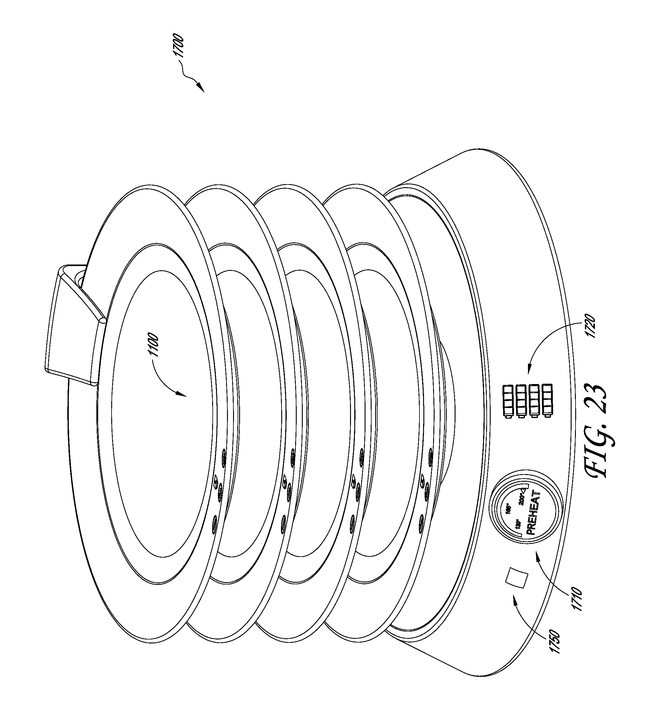
D00027

D00028

D00029

D00030
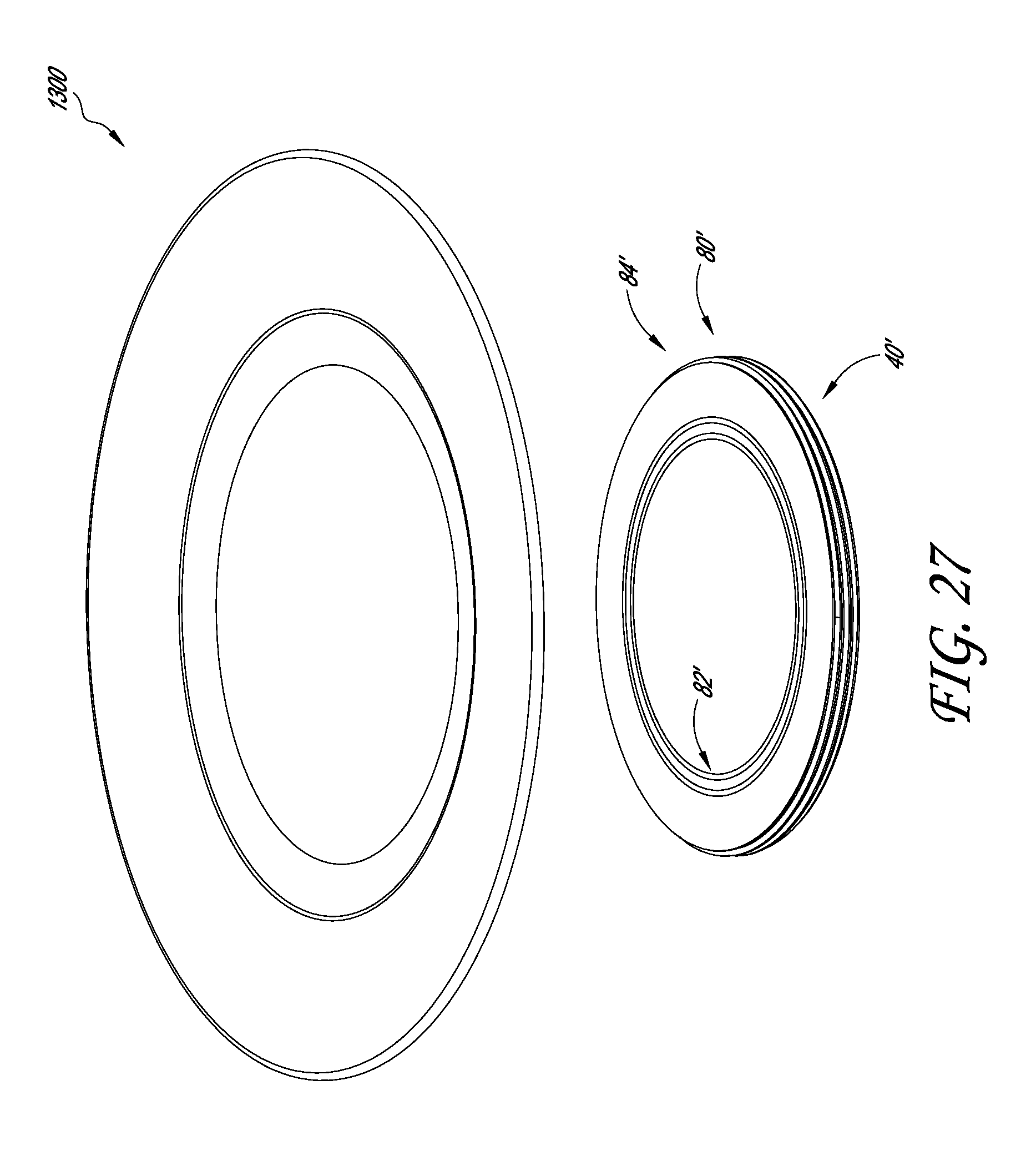
D00031

D00032

D00033

D00034

D00035

D00036

XML
uspto.report is an independent third-party trademark research tool that is not affiliated, endorsed, or sponsored by the United States Patent and Trademark Office (USPTO) or any other governmental organization. The information provided by uspto.report is based on publicly available data at the time of writing and is intended for informational purposes only.
While we strive to provide accurate and up-to-date information, we do not guarantee the accuracy, completeness, reliability, or suitability of the information displayed on this site. The use of this site is at your own risk. Any reliance you place on such information is therefore strictly at your own risk.
All official trademark data, including owner information, should be verified by visiting the official USPTO website at www.uspto.gov. This site is not intended to replace professional legal advice and should not be used as a substitute for consulting with a legal professional who is knowledgeable about trademark law.