Anterior lumbar plate and method
Kozak , et al. December 31, 2
U.S. patent number 8,617,224 [Application Number 13/204,195] was granted by the patent office on 2013-12-31 for anterior lumbar plate and method. This patent grant is currently assigned to Warsaw Orthopedic, Inc.. The grantee listed for this patent is Lawrence M. Boyd, Bradley T. Estes, Jeffrey Kozak. Invention is credited to Lawrence M. Boyd, Bradley T. Estes, Jeffrey Kozak.
| United States Patent | 8,617,224 |
| Kozak , et al. | December 31, 2013 |
Anterior lumbar plate and method
Abstract
A plate of biocompatible material is provided having curvature in two planes such that it conforms to the curvature of the L5 vertebral body and to the patient's lordotic curve. Holes are provided receiving screws for anchorage in the vertebral body and sacrum. A flange or foot portion on the plate provides a wider base end area for support in the L5-S1 interspace. The foot portion is also arranged for appropriate entry angle of screws into the sacrum such as to improve anchorage in the sacrum. Anti-backout and low profile features are incorporated. The anterior lumbar plate is situated to maintain the anterior interbody bone graft in compression by resisting tensile forces during extension.
| Inventors: | Kozak; Jeffrey (Houston, TX), Estes; Bradley T. (Memphis, TN), Boyd; Lawrence M. (Durham, NC) | ||||||||||
|---|---|---|---|---|---|---|---|---|---|---|---|
| Applicant: |
|
||||||||||
| Assignee: | Warsaw Orthopedic, Inc.
(Warsaw, IN) |
||||||||||
| Family ID: | 24795830 | ||||||||||
| Appl. No.: | 13/204,195 | ||||||||||
| Filed: | August 5, 2011 |
Prior Publication Data
| Document Identifier | Publication Date | |
|---|---|---|
| US 20110288587 A1 | Nov 24, 2011 | |
Related U.S. Patent Documents
| Application Number | Filing Date | Patent Number | Issue Date | ||
|---|---|---|---|---|---|
| 10843110 | May 11, 2004 | 8016863 | |||
| 09696130 | May 25, 2004 | 6740088 | |||
| Current U.S. Class: | 606/290 |
| Current CPC Class: | A61B 17/8042 (20130101); A61B 17/7055 (20130101); A61B 17/7059 (20130101); Y10S 606/90 (20130101); A61B 17/8047 (20130101) |
| Current International Class: | A61B 17/70 (20060101); A61B 17/80 (20060101) |
| Field of Search: | ;606/60,70,71,246-279,280-299,300-331 |
References Cited [Referenced By]
U.S. Patent Documents
| 3659595 | May 1972 | Haboush |
| 3695259 | October 1972 | Yost |
| 3741205 | June 1973 | Markolf et al. |
| 4289123 | September 1981 | Dunn |
| 4488543 | December 1984 | Tornier |
| 4493317 | January 1985 | Klaue |
| 4503848 | March 1985 | Caspar et al. |
| 4794918 | January 1989 | Wolter |
| 4800874 | January 1989 | David |
| 4938769 | July 1990 | Shaw |
| 4944757 | July 1990 | Martinez et al. |
| 4957497 | September 1990 | Hoogland et al. |
| 4963152 | October 1990 | Hofmann et al. |
| 5061271 | October 1991 | Van Zile |
| 5092893 | March 1992 | Smith |
| 5127912 | July 1992 | Ray et al. |
| 5127914 | July 1992 | Calderale et al. |
| 5147361 | September 1992 | Ojima et al. |
| 5180381 | January 1993 | Aust et al. |
| 5318567 | June 1994 | Vichard |
| 5324290 | June 1994 | Zdeblick et al. |
| 5364399 | November 1994 | Lowery et al. |
| 5397363 | March 1995 | Gelbard |
| 5397364 | March 1995 | Kozak et al. |
| 5423826 | June 1995 | Coates et al. |
| 5520690 | May 1996 | Errico et al. |
| 5527311 | June 1996 | Procter et al. |
| 5534027 | July 1996 | Hodorek |
| 5549612 | August 1996 | Yapp et al. |
| 5569250 | October 1996 | Sarver et al. |
| 5578034 | November 1996 | Estes |
| 5603713 | February 1997 | Aust et al. |
| 5607426 | March 1997 | Ralph et al. |
| 5616144 | April 1997 | Yapp et al. |
| 5634926 | June 1997 | Jobe |
| 5676666 | October 1997 | Oxland et al. |
| 5766175 | June 1998 | Martinotti |
| 5785713 | July 1998 | Jobe |
| 5800433 | September 1998 | Benzel et al. |
| 5843082 | December 1998 | Yuan et al. |
| 5888223 | March 1999 | Bray |
| 5904683 | May 1999 | Pohndorf et al. |
| 5951558 | September 1999 | Fiz |
| 6017345 | January 2000 | Richelsoph |
| 6022350 | February 2000 | Ganem |
| 6030389 | February 2000 | Wagner et al. |
| 6036693 | March 2000 | Yuan et al. |
| 6045552 | April 2000 | Zucherman et al. |
| 6139550 | October 2000 | Michelson |
| 6152927 | November 2000 | Farris et al. |
| 6156037 | December 2000 | LeHuec et al. |
| 6183478 | February 2001 | Konieczynski |
| 6193721 | February 2001 | Michelson |
| 6224602 | May 2001 | Hayes |
| 6228085 | May 2001 | Theken et al. |
| 6235034 | May 2001 | Bray |
| 6258089 | July 2001 | Campbell et al. |
| 6261291 | July 2001 | Talaber et al. |
| 6280445 | August 2001 | Morrison et al. |
| 6290703 | September 2001 | Ganem |
| 6306139 | October 2001 | Fuentes |
| 6315779 | November 2001 | Morrison et al. |
| 6331179 | December 2001 | Freid et al. |
| 6383186 | May 2002 | Michelson |
| 6416528 | July 2002 | Michelson |
| 6432106 | August 2002 | Fraser |
| 6454769 | September 2002 | Wagner et al. |
| 6461359 | October 2002 | Tribus et al. |
| 6533786 | March 2003 | Needham et al. |
| 6565571 | May 2003 | Jackowski et al. |
| 6592586 | July 2003 | Michelson |
| 6599290 | July 2003 | Bailey et al. |
| 6605090 | August 2003 | Trieu et al. |
| 6620163 | September 2003 | Michelson |
| 6652525 | November 2003 | Assaker et al. |
| 6740088 | May 2004 | Kozak et al. |
| 6793658 | September 2004 | LeHuec et al. |
| 6884242 | April 2005 | LeHuec et al. |
| 7288095 | October 2007 | Baynham et al. |
| 7399301 | July 2008 | Michelson |
| 8016863 | September 2011 | Kozak et al. |
| 2001/0014807 | August 2001 | Wagner et al. |
| 2002/0022843 | February 2002 | Michelson |
| 2002/0147450 | October 2002 | LeHuec et al. |
| 2004/0143266 | July 2004 | Kozak et al. |
| 2005/0027293 | February 2005 | LeHuec et al. |
| 0 455 255 | Nov 1991 | EP | |||
| 0 599 766 | Jun 1994 | EP | |||
| 0 867 149 | Sep 1998 | EP | |||
| 2 732 418 | Oct 1996 | FR | |||
| 2 740 321 | Apr 1997 | FR | |||
| WO 96/14802 | May 1993 | WO | |||
| WO 95/11632 | May 1995 | WO | |||
| WO 95/25474 | Sep 1995 | WO | |||
| WO 97/37620 | Oct 1997 | WO | |||
| WO 99/04718 | Feb 1999 | WO | |||
| WO 99/21502 | May 1999 | WO | |||
| WO 99/56653 | Nov 1999 | WO | |||
| WO 00/24325 | May 2000 | WO | |||
| WO 00/78238 | Dec 2000 | WO | |||
| WO 02/058574 | Aug 2002 | WO | |||
| WO 02/080791 | Oct 2002 | WO | |||
Parent Case Text
REFERENCE TO RELATED APPLICATIONS
The present application is a divisional of U.S. patent application Ser. No. 10/843,110, filed on May 11, 2004, now allowed, which is a continuation of application Ser. No. 09/696,130, filed on Oct. 25, 2000, which is now issued as U.S. patent No. 6,740,088. The referenced applications each being hereby incorporated by reference herein in their respective entireties.
Claims
What is claimed is:
1. An anti-backout system for screws, said system forming part of an anterior orthopedic plate system for attachment and joining of multiple vertebrae, said system comprising: a bone screw having a threaded portion received through an aperture in a member and having a head prevented from movement through said aperture by a stop surface on said member, the head having a tapered exterior surface thereon; and an anti-backout screw received in said member such that axes defined by said bone screw and said anti-backout screw extend parallel to one another, said anti-backout screw having a head thereon with a tapered exterior surface matable with the exterior surface of said bone screw to prevent relative rotational movement between said screws upon mating engagement of said tapered surface; wherein said member is an orthopedic plate having an anterior surface and an opposed posterior surface for facing the vertebrae, said plate further having an upper portion and a lower portion, said upper and lower portions directly coming together, said upper portion having two opposed side surfaces and an upper surface each bounding said anterior and posterior surfaces, said opposed side surfaces of said upper portion being parallel and having a first thickness, said opposed side surfaces of said upper portion having a first width measured between them, and said lower portion having two opposed side surfaces and a lower surface each bounding said anterior and posterior surfaces, said opposed side surfaces of said lower surface being curved outward away from each other, so that a second width measured between said opposed side surfaces of said lower surface is larger than said first width, said opposed side surfaces having a thickness that gets larger from the place where said upper and lower portions come together toward said lower surface, said upper portion having two holes for bone screws separated by a first distance, said lower portion having two holes for bone screws separated by a second distance that is greater than said first distance, and said holes in said lower portion each having a rim and a secondary threaded hole through said rim and below said anterior surface; wherein said bone screw is inserted through one of said holes in said upper and lower portions, and wherein said anti-backout screw is inserted into said plate.
2. The apparatus of claim 1, wherein said anti-backout screw is inserted into one of said secondary threaded holes.
3. The apparatus of claim 1, wherein said anti-backout screw contacts said bone screw.
4. An apparatus, comprising: an anterior orthopedic plate for attachment and joining of multiple vertebrae having an anterior surface and an opposed posterior surface for facing the vertebrae, said plate further having an upper portion and a lower portion, said upper and lower portions directly coming together, said upper portion having two opposed side surfaces and an upper surface each bounding said anterior and posterior surfaces, said opposed side surfaces of said upper portion being parallel and having a first thickness, said opposed side surfaces of said upper portion having a first width measured between them, and said lower portion having two opposed side surfaces and a lower surface each bounding said anterior and posterior surfaces, said opposed side surfaces of said lower surface being curved outward away from each other, so that a second width measured between said opposed side surfaces of said lower surface is larger than said first width, said opposed side surfaces having a thickness that gets larger from the place where said upper and lower portions come together toward said lower surface, said upper portion having two holes for bone screws separated by a first distance, said lower portion having two holes for bone screws separated by a second distance that is greater than said first distance, and said holes in said lower portion each having a rim and a secondary threaded hole through said rim and below said anterior surface; first and second bone screws, said first bone screw inserted through one of said holes in said upper portion and said second bone screw inserted through the other of said holes in said upper portion; third and fourth bone screws, said third bone screw inserted through one of said holes in said lower portion and said fourth bone screw inserted through the other of said holes in said lower portion; and an anti-backout system for maintaining at least two of said bone screws in said plate, said anti-backout system including an anti-backout screw received in said plate and a head portion with a surface for covering the exterior surface of at least one of said bone screws to prevent backing out of said at least one of said bone screws upon fixation of said anti-backout system.
5. The apparatus of claim 4, wherein said third and fourth bone screws each have a shank that extends from said posterior surface of said plate, and when said third and fourth bone screw are fixed with respect to said plate, said shanks point away from said upper surface of said upper portion of said plate.
6. The apparatus of claim 5, wherein said third and fourth bone screws extend through said bottom surface of said lower portion of said plate.
7. The apparatus of claim 4, wherein said plate includes a slot about midway between said upper surface and said lower surface, said slot having a length dimension substantially perpendicular to said longitudinal axis and a width dimension smaller than said length dimension and substantially parallel to said longitudinal axis, said slot allowing said plate to be bent approximately at the conjunction of said upper portion and said lower portion.
8. The apparatus of claim 4, wherein said anti-backout screw is entirely below the level of the anterior surface of the plate when fully inserted.
9. The apparatus of claim 4, wherein at least one of said secondary threaded holes has a portion through said anterior surface.
10. The apparatus of claim 9, wherein said anti-backout screw is threaded into one of said secondary threaded holes having a portion through said anterior surface.
11. The apparatus of claim 4, wherein said plate is curved in both a horizontal plane and a vertical plane so that said posterior surface is concavely curved in both a horizontal plane and a vertical plane.
12. The apparatus of claim 4, wherein said plate includes a longitudinal axis and slot about midway between said upper surface and said lower surface, said slot having a length dimension substantially perpendicular to said longitudinal axis and a width dimension smaller than said length dimension and substantially parallel to said longitudinal axis, said slot allowing said plate to be bent approximately at the conjunction of said upper portion and said lower portion, and wherein said length dimension of said slot is about six times the width dimension of said slot.
13. The apparatus of claim 4, wherein said plate has a pear-shape as viewed from the front.
14. The apparatus of claim 13, wherein said pear-shaped plate has an upper portion having straight, parallel side edges between said anterior and posterior faces defining a width, and a lower portion conjoined with said upper portion having outwardly curved side edges defining a width greater than said width of said upper portion, wherein said outwardly curved side edges are conjoined with said straight, parallel side edges.
15. An anterior orthopedic plate system with an anti-backout device for maintaining bone screws in the plate, comprising: an orthopedic plate having an anterior surface and an opposed posterior surface for facing the vertebrae, said plate further having an upper portion and a lower portion, said upper and lower portions directly coming together, said upper portion having two opposed side surfaces and an upper surface each bounding said anterior and posterior surfaces, said opposed side surfaces of said upper portion being parallel and having a first thickness, said opposed side surfaces of said upper portion having a first width measured between them, and said lower portion having two opposed side surfaces and a lower surface each bounding said anterior and posterior surfaces, said opposed side surfaces of said lower surface being curved outward away from each other, so that a second width measured between said opposed side surfaces of said lower surface is larger than said first width, said opposed side surfaces having a thickness that gets larger from the place where said upper and lower portions come together toward said lower surface, wherein said plate includes a longitudinal axis and slot about midway between said upper surface and said lower surface, said slot having a length dimension substantially perpendicular to said longitudinal axis and a width dimension smaller than said length dimension and substantially parallel to said longitudinal axis, said slot allowing said plate to be bent approximately at the conjunction of said upper portion and said lower portion, and wherein two bone screw holes are formed in said upper portion, said bone screw holes in said upper portion being separated by a first distance, and two bone screw holes are formed in said lower portion, said bone screw holes in said lower portion being separated by a second distance that is greater than said first distance, and wherein said anti-backout device is adjacent to said bone screw holes in said upper portion to prevent screws in said bone screw holes in said upper portion from backing out of the plate through said bone screw holes in said upper portion.
16. The apparatus of claim 15, wherein said plate is curved in both a horizontal plane and a vertical plane so that said posterior surface is concavely curved in both a horizontal plane and a vertical plane.
17. The apparatus of claim 15, wherein said length dimension of said slot is about six times the width dimension of said slot.
Description
BACKGROUND OF THE INVENTION
1. Field of the Invention
This invention relates generally to spinal fixation systems, and more particularly to a plate to immobilize the L5 vertebra with respect to the S1 vertebra.
2. Description of Prior Art
Various types of plating devices and systems, have been used to stabilize portions of the spine. For cases in which interbody fusion is desired in the lumbar-sacral region, stabilization using plating has been preferred by many surgeons for good fixation and to avoid damage to the vascular and nervous system components adjacent the anterior surfaces of the L5 vertebra. A plating system for stabilization of the L5-S1 junction is disclosed in U.S. Pat. No. 5,127,912 issued Jul. 7, 1992 to Ray and Ashman. It is a posterior system. While posterior fixation systems are often used in anterior/posterior fusions, the anterior surgical approach to the fusion is preferred from several perspectives. Less blood loss and reduced post-operative pain can be achieved. Also, effective anterior plating could avoid the additional posterior surgery necessary in the past to provide the additional stabilization needed to establish a reasonable fusion rate.
U.S. Pat. No. 6,045,552 issued Apr. 4, 2000 to Zucherman and Hsu discloses a plate for immobilizing the L5 vertebra with respect to the S1 vertebra. Earlier patents and publications are cited in that patent. Also, it is understood that Kostuick and Yuan had modified anterio-lateral plates, for example (e.g., the Syracuse I Plate) for use on the anterior lumbar spine. Also, it is understood that earlier literature reported clinical experience (Humphries and Hawk 1951, 1961) with an anterior lumbar plate manufactured by Austenal Company, New York. There remains a need for additional stability to an anterior lumbar interbody fusion using the same anterior surgical site for plating.
SUMMARY OF THE INVENTION
Described briefly according to the illustrated embodiment of the invention, a plate is provided having curvature in two planes such that it conforms to the curvature of the L5 vertebral body and the patient's lordotic curve. Holes are provided receiving screws for anchorage in the vertebral body and sacrum. The screws and receiver holes in an upper portion of the plate are generally perpendicular to that portion of the plate. A lower portion of the plate is formed with a flange or foot portion which provides a wider base end area for support on the upper face of S1 in the L5-S1 interspace. The foot portion is also arranged for appropriate entry angle of screws into the sacrum such as to improve anchorage in the sacrum. The screws and receiver holes in the lower portion of the plate are through the front and bottom walls of the lower portion of the plate and at a steep angle relative to the front of the plate and engaged with the.cortical bone of the sacrum at the superior end plate and at the S1-S2 junction. The foot portion also incorporates anti-backout and low profile features. The anterior lumbar plate is situated to maintain the anterior interbody bone graft in compression by resisting tensile forces during extension. The plate can also be extended to the L4-L5 junction by increasing the length of the plate and inclusion of holes in the upper portion for anchoring to L4.
BRIEF DESCRIPTION OF THE DRAWINGS
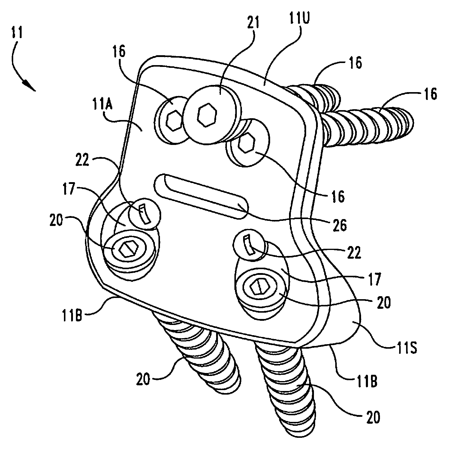
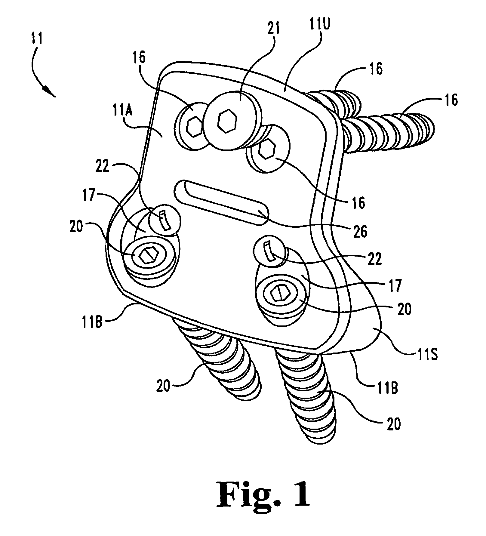
FIG. 1 is a perspective view of an anterior lumbar plate assembly according to a typical embodiment of the present invention.
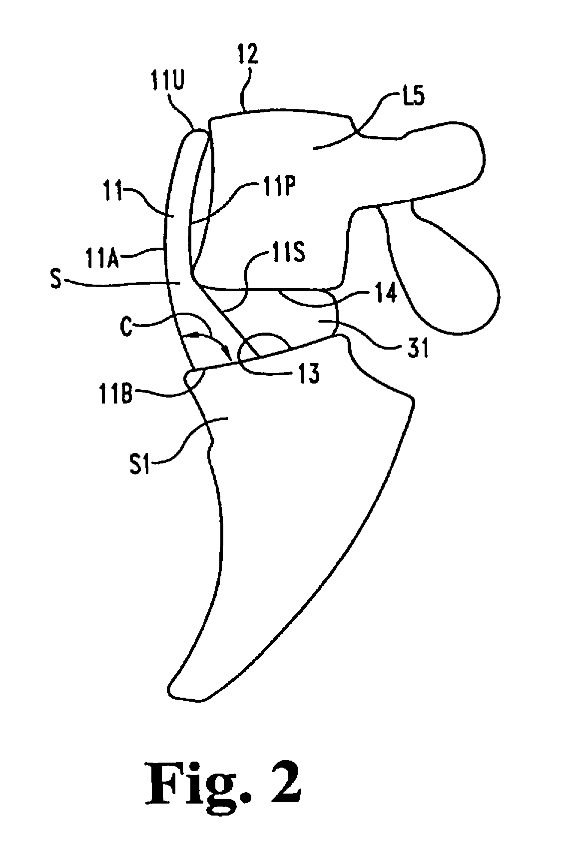
FIG. 2 is a side elevational view of the plate fixed at the L5-S1 junction of the lumbar/sacral region shown schematically.
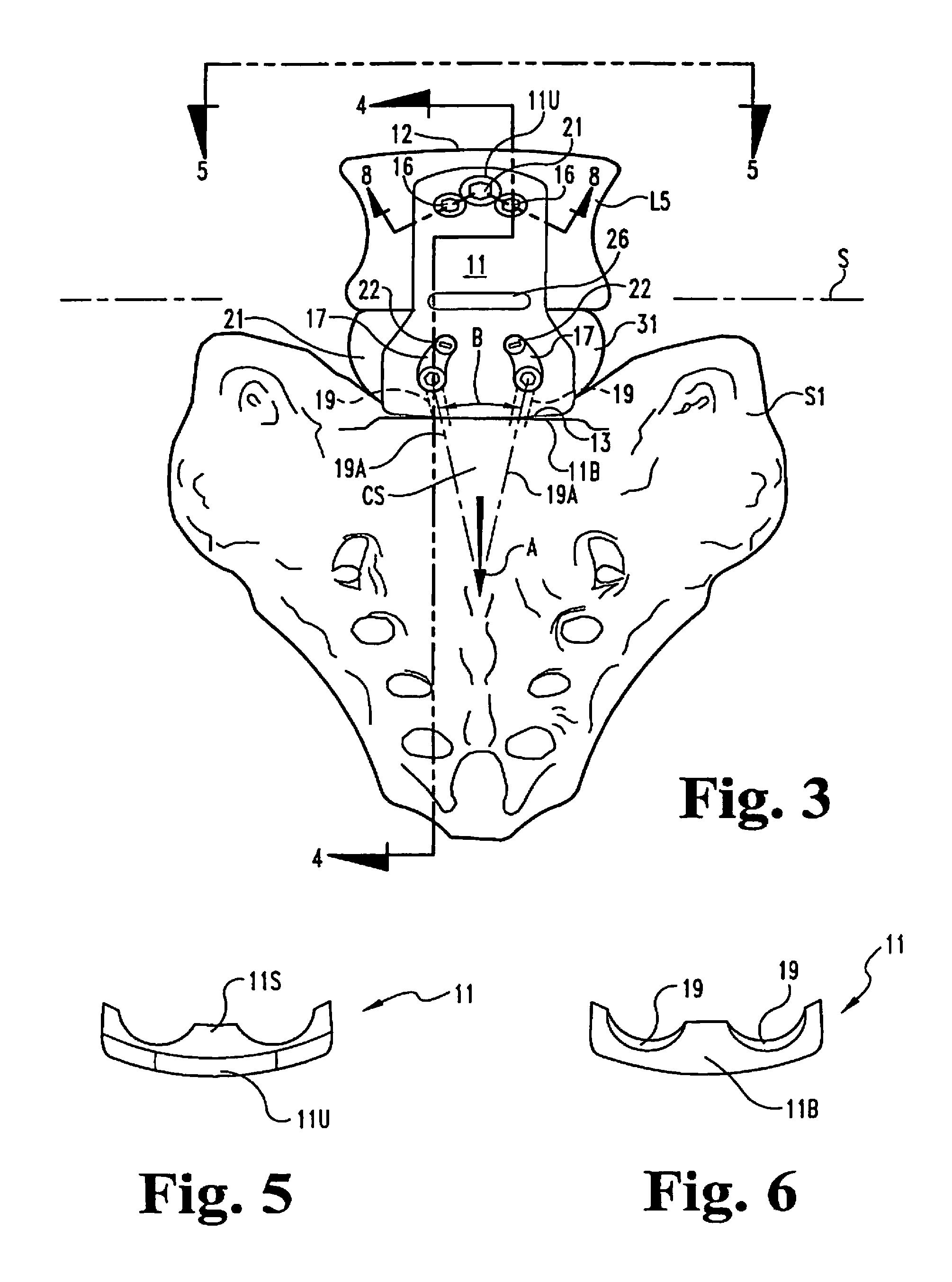
FIG. 3 is an anterior view of the plate of FIGS. 1 and 2 fixed at the L5-S1 junction.
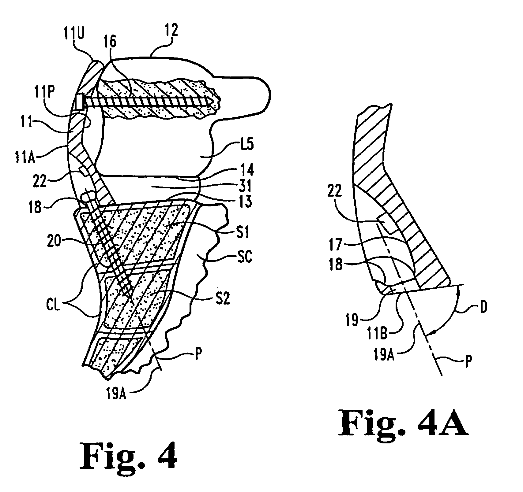
FIG. 4 is a sectional view taken at line 4-4 in FIG. 3 and viewed in the direction of the arrows and showing the plate fixed to L5 and S1, S2, shown schematically and fragmentarily.
FIG. 4A is an enlarged fragment of FIG. 4.
FIG. 5 is a top plan view of the anterior lumbar plate.
FIG. 6 is a bottom plan view of the plate.
FIG. 7 is a schematic illustration of the load bearing of the plate on the ring apophysis of the sacrum.
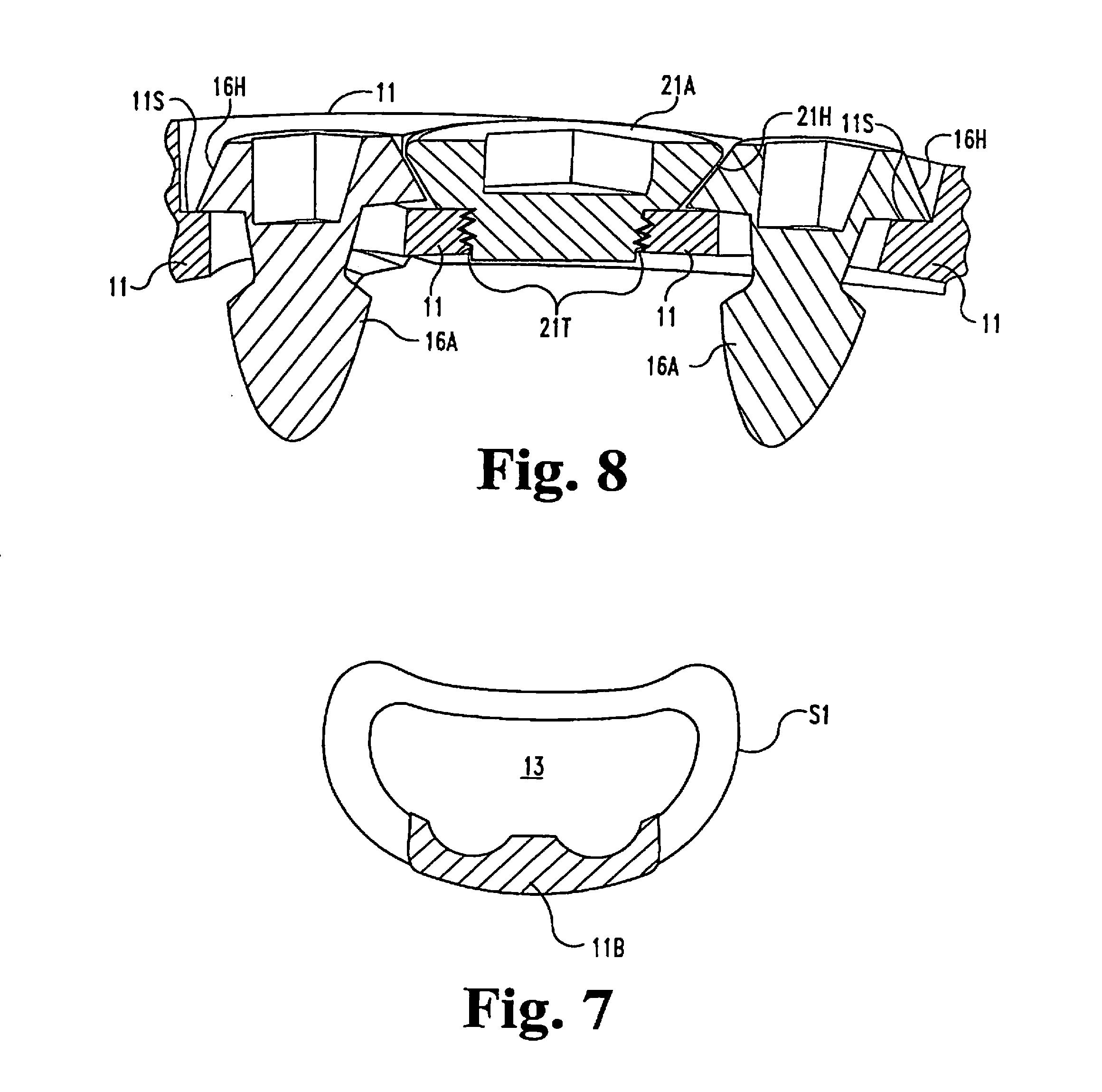
FIG. 8 is a fragmentary sectional view through a portion of the plate 11 at line 8-8 in FIG. 3 and viewed in the direction of the arrows.
DESCRIPTION OF THE ILLUSTRATED EMBODIMENT
For the purposes of promoting an understanding of the principles of the invention, reference will now be made to the embodiment illustrated in the drawings and specific language will be used to describe the same. It will nevertheless be understood that no limitation of the scope of the invention is thereby intended, such alterations and further modifications in the illustrated device, and such further applications of the principles of the invention as illustrated therein being contemplated as would normally occur to one skilled in the art to which the invention relates.
The anterior lumbar plate 11 according to the illustrated embodiment of the invention is generally pear-shaped as viewed from the front in FIG. 3 to reduce contact with great vessels, but is curved in a vertical plane as shown in FIGS. 2 and 4, and is curved in a horizontal plane as shown in FIGS. 5 and 6. This facilitates fitting around the vertebra L5 and enables the anterior face 11A (FIGS. 2 and 4) to smoothly follow the curvature of S1 and the spinal column above it. The upper portion 11P of the posterior face follows the same curves but changes at the foot portion 11S so it can partially enter the intradiscal space between L5 and S1. It is preferable that the upper end 11U of the plate be slightly lower than the top surface 12 of L5. The lower face 11B of the foot portion 11S of plate 11 is intended to be located at or immediately above the superior plate face 13 of S1.
Depending upon the anatomy of the patient, the overall height between the bottom face 11B and top edge 11U of the plate is likely to be between 4.0 centimeters and 5.4 centimeters with an average of about 4.5 centimeters. The overall width may be about 2.8 centimeters at the narrow portion and about 4.0 centimeters at the foot portion. The depth (thickness) between front and rear faces of the upper portion of the plate is about 5 millimeters and increases from slot 26 down to a maximum of about 9 millimeters at the face 11B. As mentioned above, if it is desired to extend the plate to stabilize two levels, that can be simply done by increasing the overall height between the bottom face 11B of the plate and the top edge of the plate and adding screw holes of the type discussed below to anchor into the L4 vertebra.
As shown in FIGS. 3 and 4, there are two screw holes in the upper portion of the plate and which receive screws 16 which are screwed into L5. The foot portion of the plate has two recesses 17 with lower wall portions 18 curving inwardly FIG. 4A and providing screw guide entrances to holes 19 which extend from there through the bottom face 11B. Screws 20 are received downward through holes 19 and screwed into and through both cortical bone at the superior end plate and cancellous bone of S1, and through cortical bone of both vertebral segments at the junction S1-S2. As an example, the screws may be 6.5 mm diameter cancellous bone screws. The screw hole axes 19A are also oriented from the screw entry surfaces of recesses 17 toward the longitudinal axis A of the plate which is usually substantially co-planar with the mid-plane of the spine. The trajectory for screws 20 and resulting angle B and the angle D (FIG. 4A) of the plane P relative to the plane of the plate bottom 11B, are determined by the surgeon using direct visual and X-ray fluoroscopy of the sacrum. It is expected that the included angle (B) is likely to be between 10 and 30 degrees if measured in a plane P of the screw axes (FIG. 4) or a plane close to the screw axes if they are not co-planar. The underside of the heads of screws 20 are preferably rounded above the smooth shank portions of the screws received in the holes 19, so that the screw heads can become well seated in the curved seating surface 18 by permitting some angulation of the screws relative to the plate 11 as the screws are installed in the sacrum and tightened in place.
Anti-backout means are provided. In the illustrated example, an anti-backout screw 21 (FIG. 3) is screwed into the plate and extends over the heads of the two screws 16 to prevent them from backing out of the bone L5. Screw 21 may be of the nature shown in U.S. Pat. No. 5,364,399 to Lowery et al. Alternatives are possible. One example is an interlocking wedge feature of anti-backout screw and bone screws to prevent them from backing out. In that connection, and referring to FIG. 8, which is a section taken at line 8-8 in FIG. 3 and viewed in the direction of the arrows, in this instance, the particular screws are bone screws 16A which are anchored in the vertebral body and seat on the screw shoulders 11S of plate 11 and anchor the plate 11 to the vertebral body L5. The anti-backout screw 21 is threaded into the plate 11 at the inter-engaging threads 21T. The angled heads of these screws as shown at 16H for screws 16A and 21H for the anti-backout screw 21, act as male and female Morse tapers. The holes in plate 11 are counter-sunk at the diameter of the largest part of the head of the bone screw (i.e. at the bottom of the head). The set screw 21 is placed in the threaded aperture between the bone screws in position to mate with the heads of the bone screws. The countersink bottom surface 11S may be at the same depth for all three screws.
The set screw arrangement can be used regardless of whether the screws 16 or 16A are rigid or semi-rigid. If the geometry of the plate 11 is such that the set screw 21 seats rigidly against the heads of screw 16, it is considered a rigid construct. If, however, a gap is left between the underneath side of the set screw 21, and the top of the bone screws, the bone screws are semi-rigid, allowing motion superiorly and inferiorly, effectively allowing subsidence of the interbody graft. In the example of FIG. 8, the set screw 21A is seated on the top of 11S of the countersink (counter-bore) in the plate, and allows some gap between its Morse tapered face 21H and the matable Morse tapered faces 16H of the bone screws. But in the event of any tendency of the bone screw to back out, the wedging between those surfaces will take place and terminate any back-out. This arrangement of the interlocking taper between the two bone screws and the anti-backout screw can be expanded in a way such that the anti-backout screw is centered in an array of four bone screws.
Referring now to FIG. 7, there is shown the-shape 11B of the bottom of plate 11 superimposed on the ring apophysis of the sacrum S1, demonstrating the plate 11 load-bearing on the strong ring apophysis for improved long-term fixation.
Anti-backout screws 22 are provided in the recesses 17 and positioned to prevent the screws 20 from backing out of the S1 bone. Other anti-backout approaches may be used. Another example is a nickel-titanium, shape memory alloy collar arrangement as disclosed in U.S. Pat. No. 5,578,034 to Estes. The near-vertical orientation of the screws 20 relative to the plate face 11B, and thereby to the superior end plate surface of S1, enables screw anchorage in dense cortical bone at the sacral promontory and at the S1-S2 junction without risk of the screws entering the sacral canal SC. In addition, the orientation of the axes of the two screws 20 at an angle B (FIG. 3) assists in the anti-backout or pull-out feature of this invention as it traps a wedge of cancellous bone at CS between the two screws 20, and which is very resistant to being pulled out.
As shown in FIGS. 2 and 4, the bottom plate face 11B of the wedge or foot portion of the plate 11 is at approximately 90 degrees (angle C) with the anterior face of the plate 11. Depending upon the normal angle between the superior end plate of S1 and the inferior end plate surface of L5 as well as can be determined for a patient, the end plate angle C of the plate furnished for the procedure might be selected from 80 to 100 degrees.
In addition to appropriately choosing a size of plate to fit the patient, a plate formation assistance feature is provided. In the illustrated embodiment of the plate, this is a slot 26. This slot is about 3 millimeters wide, 18 millimeters long and located about midway between the upper end 11U and lower end 11B of the plate. The location is intended to help the surgeon appropriately bend the plate about an axis S (FIGS. 2 and 3) perpendicular to the mid-plane and located immediately below the level of the lower surface 14 of L5. This facilitates the bending deemed necessary by the surgeon to best fit the plate 11 to L5 and to S1 with the foot portion 11S extending somewhat into the anterior portion of the disc space. This is to avoid necessitating resection of some of the lower anterior portion of L5 to receive the upper portion 11A of the plate as could occur if the bend were too low and, if the bend were too high, having the anterior surface of the plate at the bend projecting too far out in the anterior direction with attendant risk of impingement of the vasculature structures and sympathetic nerve bundle.
As it is possible to encounter in different patients, a range of space between the superior plate surface 13 of S1 and inferior plate surface 14 of L5, anywhere from 12 to 18 or so millimeters at the anterior edges, it can be desirable to provide a selection of several sizes of plates and locations of the relief slots, to provide the optimum choices for the spinal surgeon. As mentioned above, if it is desirable to provide fusion at more than just the one vertebral space described, the plate can be made taller to cover an additional one or more intervertebral junctions, with screws such as 16 installed in L4 and such higher vertebrae as are associated with the fusion junctions.
An example of material which may be employed in the use of the invention is a T1 6A1-4V titanium alloy according to Standard ASTM F-136. This may be associated with various types of interbody fusion device or devices and bone graft materials 31. Examples are shown and described in U.S. Pat. No. 5,397,364 to Kozak and Boyd. Of course, the present invention may be used with other types of materials, surface finishes, and interbody fusion devices of bone dowel, push-in cage, screw-in cage, with bone graft and/or graft substitute material or other types of devices suitable for such fusion applications. The anterior surface is very smooth with rounded edges to avoid damage to the vascular and nervous systems.
While the invention has been illustrated and described in detail in the drawings and foregoing description, the same is to be considered as illustrative and not restrictive in character, it being understood that only the preferred embodiment has been shown and described and that all changes and modifications that come within the spirit of the invention are desired to be protected.
* * * * *
D00000
D00001
D00002
D00003
D00004
D00005
XML
uspto.report is an independent third-party trademark research tool that is not affiliated, endorsed, or sponsored by the United States Patent and Trademark Office (USPTO) or any other governmental organization. The information provided by uspto.report is based on publicly available data at the time of writing and is intended for informational purposes only.
While we strive to provide accurate and up-to-date information, we do not guarantee the accuracy, completeness, reliability, or suitability of the information displayed on this site. The use of this site is at your own risk. Any reliance you place on such information is therefore strictly at your own risk.
All official trademark data, including owner information, should be verified by visiting the official USPTO website at www.uspto.gov. This site is not intended to replace professional legal advice and should not be used as a substitute for consulting with a legal professional who is knowledgeable about trademark law.