Vehicular vision system
Diessner April 19, 2
U.S. patent number 11,305,691 [Application Number 16/157,215] was granted by the patent office on 2022-04-19 for vehicular vision system. This patent grant is currently assigned to MAGNA ELECTRONICS INC.. The grantee listed for this patent is Magna Electronics Inc.. Invention is credited to Horst D. Diessner.


View All Diagrams
| United States Patent | 11,305,691 |
| Diessner | April 19, 2022 |
Vehicular vision system
Abstract
A vehicular vision system includes a rearward viewing camera and a control, which includes a processor that processes image data captured by the camera. During a reversing maneuver of the vehicle, the control, via processing of captured image data, detects points of interest of detected objects. Responsive to detection of the points of interest of the detected objects, the control determines if the detected objects have height dimensions and determines that objects having a height dimension greater than a threshold height are objects of interest. During the reversing maneuver of the vehicle, the control determines distances to the determined objects of interest and determines which object of interest is closest to the vehicle. During the reversing maneuver of the vehicle, responsive to the determination of the closest object of interest rearward of the vehicle, the control determines whether the determined closest object of interest is a potential hazard.
| Inventors: | Diessner; Horst D. (Rochester Hills, MI) | ||||||||||
|---|---|---|---|---|---|---|---|---|---|---|---|
| Applicant: |
|
||||||||||
| Assignee: | MAGNA ELECTRONICS INC. (Auburn
Hills, MI) |
||||||||||
| Family ID: | 48535967 | ||||||||||
| Appl. No.: | 16/157,215 | ||||||||||
| Filed: | October 11, 2018 |
Prior Publication Data
| Document Identifier | Publication Date | |
|---|---|---|
| US 20190039518 A1 | Feb 7, 2019 | |
Related U.S. Patent Documents
| Application Number | Filing Date | Patent Number | Issue Date | ||
|---|---|---|---|---|---|
| 14359340 | 10099614 | ||||
| PCT/US2012/066570 | Nov 27, 2012 | ||||
| PCT/US2012/066571 | Nov 27, 2012 | ||||
| 61605409 | Mar 1, 2012 | ||||
| 61563965 | Nov 28, 2011 | ||||
| 61650667 | May 23, 2012 | ||||
| 61579682 | Dec 23, 2011 | ||||
| 61565713 | Dec 1, 2011 | ||||
| Current U.S. Class: | 1/1 |
| Current CPC Class: | G06V 20/58 (20220101); B60R 1/00 (20130101); H04N 5/247 (20130101); G02B 3/14 (20130101); G06T 7/246 (20170101); H04N 7/18 (20130101); G06T 2207/30252 (20130101); B60R 2300/303 (20130101); B60R 2300/8066 (20130101); B60R 2300/802 (20130101); B60R 2300/105 (20130101); B60R 2300/806 (20130101); G06T 2207/10016 (20130101); B60R 2300/8093 (20130101) |
| Current International Class: | H04N 7/18 (20060101); G06T 7/246 (20170101); G06K 9/00 (20060101); B60R 1/00 (20060101); H04N 5/247 (20060101); G02B 3/14 (20060101) |
| Field of Search: | ;348/148 |
References Cited [Referenced By]
U.S. Patent Documents
| 4967319 | October 1990 | Seko |
| 4970653 | November 1990 | Kenue |
| 5059877 | October 1991 | Teder |
| 5064274 | November 1991 | Alten |
| 5072154 | December 1991 | Chen |
| 5096287 | March 1992 | Kakinami et al. |
| 5177606 | January 1993 | Koshizawa |
| 5182502 | January 1993 | Slotkowski et al. |
| 5204778 | April 1993 | Bechtel |
| 5208701 | May 1993 | Maeda |
| 5208750 | May 1993 | Kurami et al. |
| 5214408 | May 1993 | Asayama |
| 5243524 | September 1993 | Ishida et al. |
| 5245422 | September 1993 | Borcherts et al. |
| 5276389 | January 1994 | Levers |
| 5289321 | February 1994 | Secor |
| 5305012 | April 1994 | Faris |
| 5307136 | April 1994 | Saneyoshi |
| 5351044 | September 1994 | Mathur et al. |
| 5355118 | October 1994 | Fukuhara |
| 5386285 | January 1995 | Asayama |
| 5406395 | April 1995 | Wilson et al. |
| 5408346 | April 1995 | Trissei et al. |
| 5414461 | May 1995 | Kishi et al. |
| 5426294 | June 1995 | Kobayashi et al. |
| 5430431 | July 1995 | Nelson |
| 5434407 | July 1995 | Bauer et al. |
| 5440428 | August 1995 | Hegg et al. |
| 5444478 | August 1995 | Lelong et al. |
| 5451822 | September 1995 | Bechtel et al. |
| 5469298 | November 1995 | Suman et al. |
| 5530420 | June 1996 | Tsuchiya et al. |
| 5535144 | July 1996 | Kise |
| 5535314 | July 1996 | Alves et al. |
| 5537003 | July 1996 | Bechtel et al. |
| 5539397 | July 1996 | Asanuma et al. |
| 5550677 | August 1996 | Schofield et al. |
| 5555555 | September 1996 | Sato et al. |
| 5568027 | October 1996 | Teder |
| 5574443 | November 1996 | Hsieh |
| 5648835 | July 1997 | Uzawa |
| 5661303 | August 1997 | Feder |
| 5670935 | September 1997 | Schofield et al. |
| 5699044 | December 1997 | Van Lente et al. |
| 5724316 | March 1998 | Brunts |
| 5737226 | April 1998 | Olson et al. |
| 5757949 | May 1998 | Kinoshita et al. |
| 5760826 | June 1998 | Nayar |
| 5760962 | June 1998 | Schofield et al. |
| 5761094 | June 1998 | Olson et al. |
| 5765116 | June 1998 | Wilson-Jones et al. |
| 5781437 | July 1998 | Wiemer et al. |
| 5786772 | July 1998 | Schofield et al. |
| 5790403 | August 1998 | Nakayama |
| 5790973 | August 1998 | Blaker et al. |
| 5796094 | August 1998 | Schofield et al. |
| 5837994 | November 1998 | Stam et al. |
| 5845000 | December 1998 | Breed et al. |
| 5848802 | December 1998 | Breed et al. |
| 5850176 | December 1998 | Kinoshita et al. |
| 5850254 | December 1998 | Takano et al. |
| 5867591 | February 1999 | Onda |
| 5877707 | March 1999 | Kowalick |
| 5877897 | March 1999 | Schofield et al. |
| 5878370 | March 1999 | Olson |
| 5896085 | April 1999 | Mori et al. |
| 5920367 | July 1999 | Kajimoto et al. |
| 5923027 | July 1999 | Stam et al. |
| 5929786 | July 1999 | Schofield et al. |
| 5956181 | September 1999 | Lin |
| 6049171 | April 2000 | Stam et al. |
| 6052124 | April 2000 | Stein et al. |
| 6066933 | May 2000 | Ponziana |
| 6084519 | July 2000 | Coulling et al. |
| 6091833 | July 2000 | Yasui et al. |
| 6097024 | August 2000 | Stam et al. |
| 6100811 | August 2000 | Hsu et al. |
| 6138062 | October 2000 | Usami |
| 6175300 | January 2001 | Kendrick |
| 6198409 | March 2001 | Schofield et al. |
| 6201642 | March 2001 | Bos |
| 6226061 | May 2001 | Tagusa |
| 6259423 | July 2001 | Tokito et al. |
| 6266082 | July 2001 | Yonezawa et al. |
| 6266442 | July 2001 | Laumeyer et al. |
| 6285393 | September 2001 | Shimoura et al. |
| 6285778 | September 2001 | Nakajima et al. |
| 6294989 | September 2001 | Schofield et al. |
| 6297781 | October 2001 | Turnbull et al. |
| 6302545 | October 2001 | Schofield et al. |
| 6310611 | October 2001 | Caldwell |
| 6317057 | November 2001 | Lee |
| 6320282 | November 2001 | Caldwell |
| 6353392 | March 2002 | Schofield et al. |
| 6370329 | April 2002 | Teuchert |
| 6396397 | May 2002 | Bos et al. |
| 6411204 | June 2002 | Bloomfield et al. |
| 6424273 | July 2002 | Gulla et al. |
| 6477464 | November 2002 | McCarthy et al. |
| 6498620 | December 2002 | Schofield et al. |
| 6523964 | February 2003 | Schofield et al. |
| 6553130 | April 2003 | Lemelson et al. |
| 6559435 | May 2003 | Schofield et al. |
| 6570998 | May 2003 | Ohtsuka et al. |
| 6574033 | June 2003 | Chui et al. |
| 6578017 | June 2003 | Ebersole et al. |
| 6587573 | July 2003 | Stam et al. |
| 6589625 | July 2003 | Kothari et al. |
| 6593011 | July 2003 | Liu et al. |
| 6593698 | July 2003 | Stam et al. |
| 6594583 | July 2003 | Ogura et al. |
| 6611202 | August 2003 | Schofield et al. |
| 6611610 | August 2003 | Stam et al. |
| 6627918 | September 2003 | Getz et al. |
| 6631316 | October 2003 | Stam et al. |
| 6631994 | October 2003 | Suzuki et al. |
| 6636258 | October 2003 | Strumolo |
| 6648477 | November 2003 | Hutzel et al. |
| 6650455 | November 2003 | Miles |
| 6672731 | January 2004 | Schnell et al. |
| 6678056 | January 2004 | Downs |
| 6678614 | January 2004 | McCarthy et al. |
| 6690268 | February 2004 | Schofield et al. |
| 6700605 | March 2004 | Toyoda et al. |
| 6703925 | March 2004 | Steffel |
| 6704621 | March 2004 | Stein et al. |
| 6711474 | March 2004 | Treyz et al. |
| 6714331 | March 2004 | Lewis et al. |
| 6735506 | May 2004 | Breed et al. |
| 6744353 | June 2004 | Sjonell |
| 6762867 | July 2004 | Lippert et al. |
| 6795221 | September 2004 | Urey |
| 6802617 | October 2004 | Schofield et al. |
| 6806452 | October 2004 | Bos et al. |
| 6807287 | October 2004 | Hermans |
| 6822563 | November 2004 | Bos et al. |
| 6823241 | November 2004 | Shirato et al. |
| 6824281 | November 2004 | Schofield et al. |
| 6864930 | March 2005 | Matsushita et al. |
| 6889161 | May 2005 | Winner et al. |
| 6909753 | June 2005 | Meehan et al. |
| 6946978 | September 2005 | Schofield |
| 6953253 | October 2005 | Schofield et al. |
| 6968736 | November 2005 | Lynam |
| 6975775 | December 2005 | Rykowski et al. |
| 7004606 | February 2006 | Schofield |
| 7038577 | May 2006 | Pawlicki et al. |
| 7062300 | June 2006 | Kim |
| 7065432 | June 2006 | Moisel et al. |
| 7085637 | August 2006 | Breed et al. |
| 7092548 | August 2006 | Laumeyer et al. |
| 7095786 | August 2006 | Schonfeld |
| 7113867 | September 2006 | Stein |
| 7116246 | October 2006 | Winter et al. |
| 7123168 | October 2006 | Schofield |
| 7133661 | November 2006 | Hatae et al. |
| 7149613 | December 2006 | Stam et al. |
| 7151996 | December 2006 | Stein |
| 7167796 | January 2007 | Taylor et al. |
| 7195381 | March 2007 | Lynam et al. |
| 7202776 | April 2007 | Breed |
| 7227611 | June 2007 | Hull et al. |
| 7311406 | December 2007 | Schofield et al. |
| 7325934 | February 2008 | Schofield et al. |
| 7325935 | February 2008 | Schofield et al. |
| 7336299 | February 2008 | Kostrzewski et al. |
| 7375803 | May 2008 | Bamji |
| 7380948 | June 2008 | Schofield et al. |
| 7388182 | June 2008 | Schofield et al. |
| 7402786 | July 2008 | Schofield et al. |
| 7423821 | September 2008 | Bechtel et al. |
| 7482916 | January 2009 | Au et al. |
| 7526103 | April 2009 | Schofield et al. |
| 7532109 | May 2009 | Takahama et al. |
| 7541743 | June 2009 | Salmeen et al. |
| 7561181 | July 2009 | Schofield et al. |
| 7565006 | July 2009 | Stam et al. |
| 7566851 | July 2009 | Stein et al. |
| 7567291 | July 2009 | Bechtel et al. |
| 7576767 | August 2009 | Lee et al. |
| 7586400 | September 2009 | Nagaoka |
| 7605856 | October 2009 | Imoto |
| 7616781 | November 2009 | Schofield et al. |
| 7619508 | November 2009 | Lynam et al. |
| 7633383 | December 2009 | Dunsmoir et al. |
| 7671725 | March 2010 | Tsuji |
| 7711201 | May 2010 | Wong et al. |
| 7720580 | May 2010 | Higgins-Luthman |
| 7786898 | August 2010 | Stein et al. |
| 7792329 | September 2010 | Schofield et al. |
| 7843451 | November 2010 | Lafon |
| 7855778 | December 2010 | Yung et al. |
| 7881496 | February 2011 | Camilleri et al. |
| 7925441 | April 2011 | Maemura |
| 7930160 | April 2011 | Hosagrahara et al. |
| 7949486 | May 2011 | Denny et al. |
| 8009868 | August 2011 | Abe |
| 8017898 | September 2011 | Lu et al. |
| 8064643 | November 2011 | Stein et al. |
| 8072486 | December 2011 | Namba et al. |
| 8082101 | December 2011 | Stein et al. |
| 8108097 | January 2012 | Mattes |
| 8134596 | March 2012 | Lei et al. |
| 8164628 | April 2012 | Stein et al. |
| 8203440 | June 2012 | Schofield et al. |
| 8218009 | July 2012 | Heinrich |
| 8224031 | July 2012 | Saito |
| 8228383 | July 2012 | Sugiura |
| 8233045 | July 2012 | Luo et al. |
| 8237794 | August 2012 | Moritz |
| 8254635 | August 2012 | Stein et al. |
| 8294563 | October 2012 | Shimoda et al. |
| 8300886 | October 2012 | Hoffmann |
| 8320628 | November 2012 | Cheng et al. |
| 8378851 | February 2013 | Stein et al. |
| 8421865 | April 2013 | Euler et al. |
| 8452055 | May 2013 | Stein et al. |
| 8502860 | August 2013 | Demirdjian |
| 8553088 | October 2013 | Stein et al. |
| 8712162 | April 2014 | Kirsch |
| 9205776 | December 2015 | Turk |
| 10099614 | October 2018 | Diessner |
| 2002/0005778 | January 2002 | Breed et al. |
| 2002/0011611 | January 2002 | Huang et al. |
| 2002/0113873 | August 2002 | Williams |
| 2002/0181773 | December 2002 | Higaki |
| 2003/0103142 | June 2003 | Hitomi et al. |
| 2003/0137586 | July 2003 | Lewellen |
| 2003/0222982 | December 2003 | Hamdan et al. |
| 2004/0032321 | February 2004 | McMahon et al. |
| 2004/0164228 | August 2004 | Fogg et al. |
| 2005/0219852 | October 2005 | Stam et al. |
| 2005/0237385 | October 2005 | Kosaka et al. |
| 2006/0103727 | May 2006 | Tseng |
| 2006/0250501 | November 2006 | Wildmann et al. |
| 2007/0024724 | February 2007 | Stein et al. |
| 2007/0104476 | May 2007 | Yasutomi et al. |
| 2007/0242339 | October 2007 | Bradley |
| 2008/0043099 | February 2008 | Stein et al. |
| 2008/0147321 | June 2008 | Howard et al. |
| 2008/0192132 | August 2008 | Bechtel et al. |
| 2008/0266396 | October 2008 | Stein |
| 2009/0113509 | April 2009 | Tseng et al. |
| 2009/0160987 | June 2009 | Bechtel et al. |
| 2009/0190015 | July 2009 | Bechtel et al. |
| 2009/0256938 | October 2009 | Bechtel et al. |
| 2009/0290032 | November 2009 | Zhang et al. |
| 2010/0076621 | March 2010 | Kubotani et al. |
| 2011/0216201 | September 2011 | McAndrew et al. |
| 2011/0255747 | October 2011 | Iwasaki |
| 2012/0045112 | February 2012 | Lundblad et al. |
| 2012/0069185 | March 2012 | Stein |
| 2012/0200707 | August 2012 | Stein et al. |
| 2012/0243732 | September 2012 | Swaminathan |
| 2012/0314071 | December 2012 | Rosenbaum et al. |
| 2012/0320209 | December 2012 | Vico et al. |
| 2013/0141580 | June 2013 | Stein et al. |
| 2013/0147957 | June 2013 | Stein |
| 2013/0169812 | July 2013 | Lu et al. |
| 2013/0286193 | October 2013 | Pflug |
| 2014/0043473 | February 2014 | Gupta et al. |
| 2014/0063254 | March 2014 | Shi et al. |
| 2014/0098229 | April 2014 | Lu et al. |
| 2014/0247352 | September 2014 | Rathi et al. |
| 2014/0247354 | September 2014 | Knudsen |
| 2014/0320658 | October 2014 | Pliefke |
| 2014/0333729 | November 2014 | Pflug |
| 2014/0347486 | November 2014 | Okouneva |
| 2018/0056874 | March 2018 | Lu |
| 1115250 | Jul 2001 | EP | |||
| 2377094 | Oct 2011 | EP | |||
| 2667325 | Nov 2013 | EP | |||
| H1168538 | Jul 1989 | JP | |||
| 200274339 | Mar 2002 | JP | |||
| 2012139636 | Oct 2012 | WO | |||
| 2012139660 | Oct 2012 | WO | |||
| 2012143036 | Oct 2012 | WO | |||
Other References
|
Achler et al., "Vehicle Wheel Detector using 2D Filter Banks," IEEE Intelligent Vehicles Symposium of Jun. 2004. cited by applicant . Behringer et al., "Simultaneous Estimation of Pitch Angle and Lane Width from the Video Image of a Marked Road," pp. 966-973, Sep. 12-16, 1994. cited by applicant . Broggi et al., "Multi-Resolution Vehicle Detection using Artificial Vision," IEEE Intelligent Vehicles Symposium of Jun. 2004. cited by applicant . Kastrinaki et al., "A survey of video processing techniques for traffic applications", Apr. 2003. cited by applicant . Philomin et al., "Pedestrain Tracking from a Moving Vehicle", Oct. 2000. cited by applicant . Sahli et al., "A Kalman Filter-Based Update Scheme for Road Following," IAPR Workshop on Machine Vision Applications, pp. 5-9, Nov. 12-14, 1996. cited by applicant . Sun et al., "On-road vehicle detection using optical sensors: a review", IEEE Conference on Intelligent Transportation Systems, 2004. cited by applicant . Van Leeuwen et al., "Motion Estimation with a Mobile Camera for Traffic Applications", IEEE, US, vol. 1, Oct. 3, 2000, pp. 58-63. cited by applicant . Van Leeuwen et al., "Motion Interpretation for In-Car Vision Systems", IEEE, US, vol. 1, Sep. 30, 2002, p. 135-140. cited by applicant . Van Leeuwen et al., "Real-Time Vehicle Tracking in Image Sequences", IEEE, US, vol. 3, May 21, 2001, pp. 2049-2054, XP010547308. cited by applicant . Van Leeuwen et al., "Requirements for Motion Estimation in Image Sequences for Traffic Applications", IEEE, US, vol. 1, May 24, 1999, pp. 145-150, XP010340272. cited by applicant . International Search Report and Written Opinion dated Jan. 31, 2013 for corresponding PCT Application No. PCT/US2012/066570. cited by applicant. |
Primary Examiner: Jiang; Zaihan
Attorney, Agent or Firm: Honigman LLP
Parent Case Text
CROSS REFERENCE TO RELATED APPLICATIONS
The present application is a continuation of U.S. patent application Ser. No. 14/359,340, filed May 20, 2014, now U.S. Pat. No. 10,099,614, which is a 371 national phase filing of PCT Application No. PCT/US2012/066570, filed Nov. 27, 2012, which claims the filing benefit of U.S. provisional applications, Ser. No. 61/605,409, filed Mar. 1, 2012, and Ser. No. 61/563,965, filed Nov. 28, 2011, which are hereby incorporated herein by reference in their entireties. And U.S. patent application Ser. No. 14/359,340 is a continuation-in-part of PCT Application No. PCT/US2012/066571, filed Nov. 27, 2012, which claims the filing benefit of U.S. provisional applications, Ser. No. 61/650,667, filed May 23, 2012, Ser. No. 61/605,409, filed Mar. 1, 2012, Ser. No. 61/579,682, filed Dec. 23, 2011, Ser. No. 61/565,713, filed Dec. 1, 2011, and Ser. No. 61/563,965, filed Nov. 28, 2011.
Claims
The invention claimed is:
1. A vehicular vision system, said vehicular vision system comprising: a rearward viewing camera disposed at a vehicle equipped with said vehicular vision system, said rearward viewing camera having an exterior field of view exterior and at least rearward of the equipped vehicle; a control, wherein said control comprises a processor that processes image data captured by said camera to detect objects present exterior of the equipped vehicle and in the field of view of said camera; wherein, during a reversing maneuver of the equipped vehicle, said control, via processing by said processor of captured image data, detects points of interest of detected objects present in the field of view of said camera; wherein the detected points of interest of the detected objects comprise detected corner features of the detected objects that are present in the field of view of said camera; wherein said control, via processing by said processor of captured image data and responsive to detection of the points of interest of the detected objects, determines if the detected objects have height dimensions and determines that objects having a height dimension greater than a threshold height comprise objects of interest; wherein, during the reversing maneuver of the equipped vehicle, and via processing by said processor of captured image data, said control determines distances to the determined objects of interest and determines which object of interest is closest to the equipped vehicle; and wherein, during the reversing maneuver of the equipped vehicle, and responsive to the determination of the closest object of interest rearward of the equipped vehicle, said control determines whether the determined closest object of interest is a potential hazard.
2. The vehicular vision system of claim 1, wherein, responsive to determination that the determined closest object of interest is a potential hazard, said control generates an alert to a driver of the equipped vehicle.
3. The vehicular vision system of claim 1, wherein the threshold height is greater than a height of a curb.
4. The vehicular vision system of claim 1, wherein the detected corner features of the detected objects are disposed at respective heights above ground.
5. The vehicular vision system of claim 1, wherein said control processes captured image data to determine movement vectors of the detected points of interest of the detected objects, and wherein, responsive to said processing of captured image data, said control determines whether determined movement vectors of detected points of interest of a detected object present in the field of view of said camera are indicative of the object being in a position where it may collide with the equipped vehicle.
6. The vehicular vision system of claim 5, wherein determined movement vectors that are less than a threshold pixel length are not considered indicative of an object of interest.
7. The vehicular vision system of claim 5, wherein said control determines that detected points of interest are part of an object of interest when at least one movement vector is greater than a threshold amount.
8. The vehicular vision system of claim 1, wherein said control determines objects of interest by utilizing a first and a second detection method in combination, and wherein said first method for determining objects of interest comprises at least one of Gaussian blurring and consecutive Hessian blob detection, and wherein said second method for determining objects of interest comprises a FAST9 corner detector.
9. The vehicular vision system of claim 1, wherein said control operates in one of a plurality of stages, and wherein said plurality of stages has at least four different stages comprising (i) vehicle stationary and object stationary, (ii) vehicle stationary and object moving, (iii) vehicle moving and object stationary and (iv) vehicle moving and object moving.
10. The vehicular vision system of claim 1, wherein said camera comprises part of a camera module, and wherein said camera module includes said control.
11. A vehicular vision system, said vehicular vision system comprising: a rearward viewing camera disposed at a vehicle equipped with said vehicular vision system, said rearward viewing camera having an exterior field of view exterior and at least rearward of the equipped vehicle; a control, wherein said control comprises a processor that processes image data captured by said camera to detect objects present exterior of the equipped vehicle and in the field of view of said camera; wherein, during a reversing maneuver of the equipped vehicle, said control, via processing by said processor of captured image data, detects points of interest of detected objects present in the field of view of said camera; wherein the detected points of interest of the detected objects comprise detected corner features of the detected objects that are present in the field of view of said camera, and wherein the detected corner features of the detected objects are disposed at respective heights above ground; wherein said control, via processing by said processor of captured image data and responsive to detection of the points of interest of the detected objects, determines if the detected objects have height dimensions and determines that objects having a height dimension greater than a threshold height comprise objects of interest; wherein, during the reversing maneuver of the equipped vehicle, and via processing by said processor of captured image data, said control determines distances to the determined objects of interest and determines which object of interest is closest to the equipped vehicle; wherein, during the reversing maneuver of the equipped vehicle, and responsive to the determination of the closest object of interest rearward of the equipped vehicle, said control determines whether the determined closest object of interest is a potential hazard; and wherein, responsive to determination that the determined closest object of interest is a potential hazard, said control generates an alert to a driver of the equipped vehicle.
12. The vehicular vision system of claim 11, wherein the threshold height is greater than a height of a curb.
13. The vehicular vision system of claim 11, wherein said control processes captured image data to determine movement vectors of the detected points of interest of the detected objects, and wherein, responsive to said processing of captured image data, said control determines whether determined movement vectors of detected points of interest of a detected object present in the field of view of said camera are indicative of the object being in a position where it may collide with the equipped vehicle.
14. The vehicular vision system of claim 13, wherein determined movement vectors that are less than a threshold pixel length are not considered indicative of an object of interest.
15. The vehicular vision system of claim 13, wherein said control determines that detected points of interest are part of an object of interest when at least one movement vector is greater than a threshold amount.
16. A vehicular vision system, said vehicular vision system comprising: a rearward viewing camera disposed at a vehicle equipped with said vehicular vision system, said rearward viewing camera having an exterior field of view exterior and at least rearward of the equipped vehicle; a control, wherein said control comprises a processor that processes image data captured by said camera to detect objects present exterior of the equipped vehicle and in the field of view of said camera; wherein, during a reversing maneuver of the equipped vehicle, said control, via processing by said processor of captured image data, detects points of interest of detected objects present in the field of view of said camera; wherein the detected points of interest of the detected objects comprise detected corner features of the detected objects that are present in the field of view of said camera; wherein said control, via processing by said processor of captured image data and responsive to detection of the points of interest of the detected objects, determines if the detected objects have height dimensions and determines that objects having a height dimension greater than a threshold height comprise objects of interest; wherein the threshold height is greater than a height of a curb; wherein, during the reversing maneuver of the equipped vehicle, and via processing by said processor of captured image data, said control determines distances to the determined objects of interest and determines which object of interest is closest to the equipped vehicle; wherein, during the reversing maneuver of the equipped vehicle, and responsive to the determination of the determined closest object of interest rearward of the equipped vehicle, said control determines whether the determined closest object of interest is a potential hazard; and wherein, responsive to determination that the determined closest object of interest is a potential hazard, said control generates an alert to a driver of the equipped vehicle.
17. The vehicular vision system of claim 16, wherein said camera comprises part of a camera module, and wherein said camera module includes said control.
18. The vehicular vision system of claim 16, wherein the detected corner features of the detected objects are disposed at respective heights above ground.
19. The vehicular vision system of claim 16, wherein said control processes captured image data to determine movement vectors of the detected points of interest of the detected objects, and wherein, responsive to said processing of captured image data, said control determines whether determined movement vectors of detected points of interest of a detected object present in the field of view of said camera are indicative of the object being in a position where it may collide with the equipped vehicle.
20. The vehicular vision system of claim 19, wherein said control determines that detected points of interest are part of an object of interest when at least one movement vector is greater than a threshold amount.
Description
FIELD OF THE INVENTION
The present invention relates to imaging systems or vision systems for vehicles.
BACKGROUND OF THE INVENTION
Use of imaging sensors in vehicle imaging systems is common and known. Examples of such known systems are described in U.S. Pat. Nos. 5,949,331; 5,670,935 and/or 5,550,677, which are hereby incorporated herein by reference in their entireties.
SUMMARY OF THE INVENTION
The present invention provides a vision system or imaging system for a vehicle that utilizes one or more cameras to capture images exterior of the vehicle, and provides the communication/data signals, including camera data or image data that is processed and, responsive to such image processing, detects an object at or near the vehicle and in the path of travel of the vehicle, such as when the vehicle is backing up.
According to an aspect of the present invention, a vision system for a vehicle includes an image sensor disposed at a rear portion of the subject vehicle and having an exterior field of view rearward of the vehicle, and a control operable to process image data captured by the image sensor to detect an object to the rear of the subject vehicle. The control is operable to process the image data to detect points of interest in the field of view of the image sensor and, responsive to the processing, the control is operable to determine movement of the detected points of interest. The control is operable to process the image data to determine movement vectors and, responsive to such processing, the control is operable to determine whether or not an object of interest is present in the field of view of the image sensor and rearward of the vehicle.
The control may determine that detected points of interest are part of an object of interest when at least one movement vector is greater than a threshold amount. The image sensor or camera may comprise a smart camera, with imaging circuitry and processing circuitry and the like incorporated into the camera or camera module.
These and other objects, advantages, purposes and features of the present invention will become apparent upon review of the following specification in conjunction with the drawings.
BRIEF DESCRIPTION OF THE DRAWINGS
FIG. 1 is a plan view of a vehicle showing typical field of view range and width for an object detection system with a rearward facing camera disposed at a rear portion of the vehicle in accordance with the present invention;
FIGS. 2 and 3 are images showing results of point of interest detections by the system of the present invention;
FIG. 4A is an image showing motion vectors attached to a moving blob or object;
FIG. 4B shows a distance estimation to a moving object within a vehicle camera image;
FIG. 4C shows a side elevation schematic of a distance estimation between the camera's viewing angle borderline to a moving object which is assumingly attached to the ground;
FIG. 5 shows an object image produced from extracting the object from FIG. 4A;
FIG. 6 shows motion vectors (produced by tracking features/POI over two or more or multiple frames) due to very slow vehicle movement, while the speedometer reads 0 [km/h];
FIG. 7 shows a differential image generated out of a steady scene (no vehicle movement) having a moving object within view (such as when the control is in the processing state: Vehicle Stationary/Object Moving), such as a moving object as shown in FIG. 4A;
FIG. 8 is a block diagram of system status that determines the activation of the moving object detection for the object detection system of the present invention;
FIG. 9 is a block diagram of an algorithm for the vehicle moving/object stationary state of the object detection system of the present invention;
FIG. 10 is a schematic of a camera focal point or camera coordinate as defined by a X-offset and Y-offset relative to the vehicle coordinate;
FIG. 11 is an image showing use of a point of interest parabola in detecting points of interest in accordance with the present invention;
FIG. 12 is a schematic showing the transformation of a point of interest when the vehicle and camera move;
FIG. 13 is a graph showing the POI plane and vector of a POI in three dimensional space, with the POI coordinate being where the plane and vector intersect;
FIG. 14 shows images of all of the POIs in the scene, and of the POIs as identified as part of the closest object using the object detection system of the present invention;
FIG. 15 shows an intensity image and an object image in accordance with the present invention;
FIG. 16 shows an overview of a smart camera suitable for use with a vision system of the present invention;
FIG. 17-19 show view transformation and machine vision capabilities of the smart camera of FIG. 16;
FIG. 20 shows a summary of the various aspects and properties of the unique feature-point based object detection for use with a vision system according the present invention;
FIG. 21 is a schematic showing a possible architecture solution when the invention's processing algorithm are integrated to a smart vehicle camera featuring different output bus interfaces; and
FIGS. 22-40 show various connections and system architecture and other aspects and constructions and features of a smart camera and associated accessories and systems for use with a vision system according the present invention.
DESCRIPTION OF THE PREFERRED EMBODIMENTS
A driver assist system and/or vision system and/or object detection system and/or alert system may operate to capture images exterior of the vehicle and process the captured image data to detect objects at or near the vehicle and in the predicted path of the vehicle, such as to assist a driver of the vehicle in maneuvering the vehicle in a rearward direction. The object detection may utilize detection and analysis of moving vectors representative of objects detected in the field of view of the vehicle camera, in order to determine which detected objects are objects of interest to the driver of the vehicle, such as when the driver of the vehicle undertakes a reversing maneuver.
The Object Detection (OD) algorithm and system of the present invention is operable to detect the closest object located behind a vehicle within a field of view of a single rearward facing camera at the rear of the vehicle. Any object which may be a hazard (i.e., may cause damage to the vehicle or may be an object that the driver of the vehicle would want to avoid) may be detected regardless of its size, shape and features. Such objects can be vehicles, posts, buildings, signs, pedestrians, bicycles, trash bins, fences, vegetation, etc. The OD algorithm is operable to report objects that are detected and for which it is determined with a height. Any objects flat on the ground, such as lane markings and road patches and/or the like, shall not be reported to the driver of the vehicle.
The objective of the OD algorithm is not to classify objects (tell what object is in the FOV), but rather the OD system is operable to warn a driver that there is something behind the vehicle with which the vehicle could collide regardless of what that object is. The Field of View (FOV) of the OD system is shown in FIG. 1.
The algorithm shall allow adjusting the height of reported objects. This allows filtering of low objects, such as curbs and the like, whereby the OD algorithm may not report such low objects.
The algorithm is operable to measure the distance between the vehicle and the closest detected object. It is not required that the measured distance be highly accurate since most OEMs use the distance to drive some sort of a display with graphic overlays or segments, such as, for example, a green, yellow or red indicator (General Motors) or a LED bar with 8 segments (Chrysler, Mercedes) or a buzzer with different interval tones (Ford, Nissan), or the like. In cases where a numeric value is displayed, it should be sufficient to display the value that is within a 10 cm resolution.
The initial algorithm is operable to minimize or reduce false positives (e.g., where an object is reported when there is not an object present behind the vehicle), since this would be a nuisance to the vehicle operator. Because the camera images are displayed to the vehicle operator, false negatives (where an object is present but may not be reported as an object of interest) may be more acceptable.
The OD algorithm may be processed by a single chip embedded processor such as a TI OMAP (commercially available from Texas Instruments) or Analog Devices Blackfin or the like (or other image processor, such as, for example, an EYEQ.TM. image processing chip available from Mobileye Vision Technologies Ltd. of Jerusalem, Israel). The processing power of such devices is limited and significantly less compared to a PC. Therefore, the algorithm may not process the full image frame since each image frame contains about 640.times.480=307,200 pixels or greater or even about 1024.times.768=786,432 pixels or greater at a frame rate of 30 frames per second (or more or less frames per second). In order to limit the data to be processed, the image may be segmented into Points-of-Interest (POI) which are processed by the OD algorithm.
A Point-of-Interest is a pixel or pixels in the image with significance, possibly part of an object. A Point-of-Interest may be located on an edge or corner of an object or on a feature of an object with strong feature content, such as a logo or license plate. The POI shall be chosen in a way that it can be relocated in the next image frame, at the same location of the object even if the object and/or the camera moved or rotated. The POI segmentation is based on the image features, and thus it is expected that POIs will be located on objects with height as well as on objects on the ground plane, such as lane markings or the like.
The method used to generate the POIs is operable to prioritize on the stability of the POIs, ensuring that they are located on the same location of the object. Therefore, the algorithm may look for strong image features such as corners. Such a method or process will detect POIs on target objects (positives) and ground features (such as lane markings, false positives) in a similar manner. Thus, the false positives will have to be discarded by the OD algorithm.
A method detecting surfaces using unsharp masks and blob detectors might work very well to detect objects in the image while minimizing false positives; but such a method might not allow detecting the same feature on an object from frame to frame. The POIs thus may move around on the object causing errors in the Real World Transform (as discussed below).
The area surrounding a Point-of-Interest may be used to define a descriptor for each POI allowing relocating the same POI from frame to frame. The descriptor may contain information such as angles of edges, color data, intensity information, and/or the like. The descriptor shall be chosen in a manner that allows it to identify the POI even if the scene moves, such as if the object is moved or rotated or the camera is moved. These changes in the object presentation are limited by the frame rate of 30 fps (because object movement may be limited in a time frame of about 33 ms).
An OD approach using POIs is usually called sparse optical flow. Such POI detections are represented in the images of FIGS. 2 and 3. Optionally, the system may utilize one of two POI methods. The first method utilizes a Gaussian blur in conjunction with a Hessian blob detector. The descriptor utilizes a polar histogram of gradients. This method appears to have few false positives, but the POIs do not match the image features in a stable manner, and hence are not located on the same location on the object from one frame to another.
The second method utilizes an edge detector and a custom descriptor. Different methods for the edge detector can be used depending on the available processing power of the embedded platform. This could be for example a FAST9 corner detector or a Harris corner detector. Such a FAST9 corner detector or accelerated segment test or AST (as is known in the video arts) or FAST (Features from Accelerated Segment Test) may be used for the edge detector. For example, a FAST that uses a value of 3 (corresponding to a circle of 16 pixels circumference) can be used but preferably a FAST9, which uses a value of 9, is used. While a FAST9 corner detector (where a segment of at least 9 contiguous pixel is detected) may be preferred, other orders of FAST corner detection algorithms may be used in particular circumstances. This method produces more false positives compared to the first method but the POIs are very stable and suitable for the OD algorithm of the present invention.
The tracker analyzes all POIs using the POI pixel coordinate and the POI descriptor from frame to frame. The tracker identifies a configurable number of POIs (initially, for example, about 400), which can be tracked from frame to frame. The system will take the minimum distance (in pixels) between POIs into consideration and will also spread the POIs across the whole image (for example, all POIs at the horizon and not on an object in the foreground may not be acceptable).
If a new object enters the scene or an object moves closer due to motion and more features become available on the object, the tracker may assign new POIs to this object. Thus, an analysis of the current number of tracked POIs and their distribution across the image is provided. The tracker assigns an identifier (ID) to each tracked POI and provides a list of tracked POIs with their pixel coordinate and ID as output. The ID can be used by the following processing steps to identify the same POI in different frames.
An analysis of objects commonly occurring behind vehicles showed that there are four detection states: Vehicle Stationary/Object Stationary Vehicle Stationary/Object Moving Vehicle Moving/Object Stationary Vehicle Moving/Object Moving Each detection state is fundamentally different in the way in which an object can be detected by the processing system; hence, a different algorithm may be developed and provided for each state. The control may comprise a state machine and may operate in one of each states or stages accordingly. Such a state machine (as known in the video arts) may comprise (i) an initial state or record of something stored someplace, (ii) a set of possible input events, (iii) a set of new states that may result from the input, and (iv) a set of possible actions or output events that result from a new state.
The state machine of the system of the present invention has at least the four different stages VEHICLE STATIONARY and OBJECT STATIONARY, VEHICLE STATIONARY and OBJECT MOVING, VEHICLE MOVING and OBJECT STATIONARY, VEHICLE MOVING and OBJECT MOVING. The control determines objects of interest that have been detected in a different stage or earlier stage when the control is in the stage VEHICLE STATIONARY and OBJECT STATIONARY. The algorithms of each individual state are described below.
Vehicle Stationary/Object Stationary:
The vehicle stationary/object stationary state or stage poses the problem that there is not enough information available to detect an object since there is no motion of the camera or object. Therefore, it may not be possible to detect the height of an object; the system would not be able to distinguish if there is a three dimensional (3D) object present or if an image of an object is painted on the ground. A two dimensional (2D) image would not reveal this information. An active detection of an object is therefore difficult in this state. Since there is no motion in this state, there is no danger of a collision between an object and the vehicle.
The OD algorithm therefore may only report an object previously detected in another state if both the vehicle and object are stationary. The location of a previously detected object would not change since there is no motion.
Vehicle Stationary/Object Moving:
The vehicle speed may be obtained by reading the wheel speeds, such as by using a vehicle CAN network. The system may determine that the vehicle is stationary if all 4 wheel speeds are zero.
A motion vector can be calculated for each POI by subtracting the POI coordinate of the current frame and with the coordinate M frames ago. Each vector has a length and orientation (angle). Short motion vectors (such as, for example, less than 2 pixels) can be considered as noise and discarded. Therefore, there will be no motion vectors if there is no moving object in the scene. If the motion vectors are longer than a threshold length or number of pixels, the motion vector is considered part of an object. An example of motions vectors on or at a moving object is shown in FIG. 4.
In order to locate the moving object in the camera images, an object image may be generated. The object image (such as shown in FIG. 5) is a binary image (only black and white pixels) with a reduced resolution in order to minimize the required computing power (for example: if the camera resolution is 640.times.480, the object image may be 640/4.times.480/4=160.times.120 pixels). The initial object image may contain only black pixels. Each starting point of a valid motion vector (the coordinate of a POI in the current frame or captured image) is set to be a white pixel in the object image. Therefore, all pixels which are detected to be moving in the current frame are white, all stationary pixels are black.
As shown in FIG. 5, the white image regions grow and merge together into one object. This is accomplished using morphology operations (dilate/erode) with a disk as a structure element.
The centroid of the white area represents the location of the object in the camera image. An overlay icon may be displayed at this location to warn the vehicle operator about the moving object. The distance to the object can be estimated assuming that the bottom of the object is connected to the ground plane. Therefore, the pixel row of the bottom of the object can be used to calculate the estimated distance taking camera mounting height and the horizontal camera angle into account. A pinhole camera model can be assumed for this calculation.
The challenge with this approach is that the wheel speeds obtained from the vehicle may read a zero speed or about zero even if the vehicle is moving very slowly (FIG. 6). The reason is that common wheel pulse counters do not provide a reliable reading for speeds less than about 1 km/h. This will cause the algorithm described above to detect motion in the case that the vehicle starts moving but the wheel speeds are still reading zero. It is desirable that such false positive detections are to be avoided since they present nuisance to the driver.
Testing has showed that the motion vectors can have a length of up to 7 pixels until the wheel pulse counters start working properly and the vehicle motion can be properly identified using the wheel speeds. Thus, in the illustrated embodiment, the threshold vector length in order to detect object motion may be set to greater than (or greater than or equal to) about nine (9) pixels in order to suppress these false positive detections. This in turn may result in not enough motion vectors remaining on a moving object in order to have stable moving object detection. If all "good" motion vectors were also filtered, the object detection may become unstable.
Particular problems may be found with walking pedestrians since the feet of a person may be too small in the camera image due to the mounting height and angle of the camera (camera is looking down). Thus, the moving feet may not be detected properly causing the distance estimation to fail. Therefore, it may be desirable to use a sparse optical flow (of POIs) to detect the vehicle motion but dense optical flow to detect moving objects.
The state machine of FIG. 8 determines the activation of the moving object detection. The AvgMotionVectorLength is the average length of all motion vectors below the horizon (in the image foreground). The detection of moving objects is only active in the state "Moving Object Detection Active".
As shown in FIG. 7, a differential image may be produced by subtracting the current gray-scale camera frame from a previous gray-scale camera frame (for example 4 frames earlier). The image can be resized to a lower resolution before the subtraction in order to decrease computing power for this operation. The differential image will show areas in the image which are moving.
The differential image may then be converted into a black and white object image. All pixels above a defined intensity are set to white, while all other pixels are set to black. The white image regions are thus grown or enlarged so that they merge together into an object or objects. This is accomplished using morphology operations (dilate/erode) with a disk as a structure element. This operation produces the object image. Each white image region represents a moving object. Additional filtering may be desired or required to remove noise and to produce a stable output.
A search algorithm finds all connected white image regions in the image. Each white image region represents an object. Each object can be described by the following parameters: Centroid Bounding box Surface area All objects with a surface area smaller than a threshold may be discarded. This removes noise but also removes small moving objects, such as, for example, leaves blown by the wind, moving foliage of bushes, trees and/or the like.
The closest object is typically the object which extends furthest down in the image. This object will be reported in the system output. The bottom edge of the bounding box of the closest object can be used to calculate the estimated distance, taking the camera mounting height and the horizontal camera angle into account. A pinhole camera model can be assumed for this calculation.
The detection of the centroid and distance using the method above may yield a somewhat unstable output. Thus, additional filtering may be required or desired. The output shows two major problems: 1. intermittent detection and 2. unstable or "jumpy" output.
Optionally, a prediction filter may be implemented to overcome intermittent detections. All parameters describing the closest object may be stored in a ring buffer with 24 elements. Therefore, up to 24 previous detections are available to be used by the prediction filter. In case the object is not detected in the current frame, the filter may predict the object centroid and distance using the previous positive detections. The ring buffer may contain at least 8 positive detections out of the previous 24 frames. The current (missing) detection may be predicted by linearly interpolating a function for each of the centroid coordinate (column and row) and the distance. The current centroid and distance is calculated using this interpolated function. The predicted centroid and distance is added into the ring buffer for the current frame.
The prediction filter may predict the object for up to 8 consecutive frames using the method described above. If the object is not detected for 8 consecutive frames, the object will not be reported anymore.
If an object enters the field of view, the detection of the object may be intermittent. The predication filter may not work properly at this time since the ring buffer is not filled yet. Therefore, a confirmation filter may be used that will allow an object only to be reported if the object was detected for K consecutive times (with K being a number selected that provides suitable confidence that the multiple (K) detections accurately indicate detection of an object). Once the object is detected K times, the filters work together ensuring a more stable the output.
Optionally, a statistical filter may be used to filter the output against jumps in the reported distance and object location. The statistical filter may use the same ring buffer as the prediction filter. The statistical filter may interpolate a linear function for each of the centroid coordinates (column and row) and the distance in case the ring buffer contains at least 12 positive detections out of the previous 24 frames. The statistical filter may calculate the expected object using the interpolated functions. The actual current object may then be compared with the expected object. Adjustments to the reported object can be made in order to filter out any unstable behavior.
Optionally, a Kalman filter may be implemented in order to reduce the jitter in the output. The Kalman filter is an algorithm which operates recursively on streams of input data (centroid and distance) to produce a statistically optimal output estimate. The predicted output may be calculated by summing the weighted current sample and weighted previous output. The predicted output and current sample may be processed using the respective standard deviations achieving a statistically optimal output.
The final reported object may be filtered with an infinite impulse response low pass filter using the last and current reported object.
In testing, a particular concern was found with objects that move away from the vehicle until they exit the field of view but then turn around and reenter the field of view. The object (for example a walking pedestrian) may not be detected immediately entering the field of view at the maximum field of view range. The reason is that the image area of the object is smaller when it enters the field of view at a distance as compared to when a moving object enters the field of view at a closer range. Therefore, an average motion vector length ("AvgMotionVectorLength") may not exceed the threshold, causing the machine to not enter into the "Moving Object Detection Active" state.
This problem may be overcome by tracking the moving object until the distance to the moving object exceeds a predetermined or threshold distance (such as two times the field of view range (2*FOV Range) or other suitable distance). The OD algorithm therefore continues to detect an object even if it is outside the field of view. The OD algorithm may not report the object to the vehicle operator in this case (when the object is outside of the field of view), but if the tracked object reenters the field of view, it can be immediately reported.
Vehicle Moving/Object Stationary:
When the object is stationary and the vehicle is moving, a similar approach as stereoscopy can be used. In stereoscopic systems, there are two camera images taken at the same time. In the system of the present invention, two images can be taken at different times and the vehicle motion may deliver the stereoscopic base. A block diagram of the algorithm for the vehicle moving/object stationary state is shown in FIG. 9.
Process Vehicle Inputs:
The center of the rear axle of the vehicle may mark the vehicle coordinate. Upon activation of the object detection system (for example: selection of reverse gear), the vehicle coordinate system is set to the origin of a world coordinate system with an angle of 0 degrees (such as shown in FIG. 10). The vehicle main axis is lined up with the y-axis of the world coordinate system.
As the vehicle is moving, the vehicle position can be defined by its coordinate in the world coordinate system and vehicle angle relative to the y-axis of the world coordinate system. The camera focal point or camera coordinate is defined by a X-offset and Y-offset relative to the vehicle coordinates.
The system or algorithm may include a block "process vehicle inputs," which tracks the camera coordinates and camera angle relative to the world coordinate system. In order to do this, the vehicle coordinate and vehicle angle is tracked in the world coordinate system using the wheel speeds and steering angle data, such as may be received through the vehicle network bus or vehicle CAN network or the like. The time-base of the tracking of the vehicle is the frame rate of the camera. Therefore, the block "process vehicle inputs" calculates the camera coordinate and orientation every time when a new frame is captured.
This allows calculating how much the camera moved in X and Y and how much the camera rotated between frames. A buffer of M frames is maintained in order to determine how much the camera moved and rotated between the current frame N and a previous frame N-M. Therefore, the block "process vehicle inputs" provides the stereoscopic base for two or more images taken of a scene.
The average camera speed may also be calculated. The average camera speed is defined as the distance the camera moves between the frames N and N-M, divided by the time elapsed between frames N and N-M. The detection of stationary objects using the vehicle motion is possible if the average camera speed is greater than a threshold amount. This ensures that the camera moves enough to provide a sufficient stereoscopic base for the Real World Transform described below.
Input Image Processing:
The transform described in the block "Real World Transform" uses a pin hole camera model. Therefore, it is desirable that the camera image be substantially or entirely or 100 percent dewarped. The dewarping can be done either: In the imager Before the image segmentation Applied to the POIs after the tracker In case the dewarping cannot be done in the imager, it may be desirable to apply the dewarping to the POIs after the tracking. This would minimize the required processing power and may increase the accuracy of the segmentation/tracker since the raw image would be used by these blocks. Real World Transform:
The real world transform uses a POI occurring in frame N and N-M and the coordinate and orientation of the camera in frame N and N-M, in order to transform the POI into the real world coordinate. The transformed POI will have X, Y and Z coordinates, hence its location is known in 3D space.
Most POIs occur on the horizon in a scene. Since the horizon is not part of the OD system's area of interest, these POIs can be discarded before the Real World transform is performed. In order to do so, a second order function may be interpolated in order to define the Region-of-Interest (ROI) in the camera image. All POIs above the parabola are discarded, all POIs below the parabola are used. An exemplary ROI parabola is shown in FIG. 11.
In order to filter noisy POIs that are not located on the same location of an object, a POI motion vector may be calculated for each POI by subtracting the POI coordinate of frame N with the POI coordinate of frame N-M. The length of the POI vector can be calculated using Pythagoras.
The length of the POI motion vector depends largely on the vehicle speed and location of the POI vector in the image. The closer the vector is to the horizon, the shorter the vector will be. Therefore, a formula of the present invention may calculate a POI motion vector length threshold based on speed and image location. All POIs that have vectors that are longer than the threshold are rejected. This removes the noise in the POI data considerably. All of the remaining POIs may be transformed using the Real World Transform described below.
The pixel row of the POI in frame N-M is used to describe a plane (POI.sub.plane) mathematically in the format =.alpha.*+.beta.*, where and are vectors from the focal point of the camera to the outer edges of the imager at pixel column 0 and pixel column 639 at the row of the POI (assuming the resolution is 640.times.480). .alpha. and .beta. are unknown and express the lengths of the vectors and .
The pixel coordinate of the POI in frame N is used to describe a vector (POI.sub.vector) mathematically in the format =.gamma.*, where is the vector from the focal point of the camera to the pixel. .gamma. is unknown and expresses the length of the vector .
Parameters, such as the imager size, imager resolution, focal length, camera rotation between frame N and N-M and the like, may be taken into account into the mathematical description of the and (see FIG. 12).
The block "process vehicle inputs" delivers the Camera.sub.Movement vector . This allows the system to formulate the following linear system: =+. This linear system of equations contains three equations (for X, Y, Z) and three unknowns (.alpha., .beta., .gamma.), and can thus be solved using a method, such as Euler or Gauss or the like. It is sufficient to solve the system only for the unknown .gamma.. Once .gamma. is known, it can be entered into the equation =*, and the 3D coordinates of the POI can be calculated.
The calculations above will provide the 3D coordinate relative to the camera focal point of the camera at frame N. A final transform will move the 3D coordinate into the vehicle coordinate system.
The graphs of FIGS. 12 and 13 show the POI plane and vector of a POI in 3D space. The POI coordinate is where the plane and vector intersect.
All POIs that are located on the ground plane (such as POIs due to lane markings or the like) can be removed from the 3D data using their Z-coordinate. Also, the desired field of view (FOV) can be applied using the X-coordinate and Y-coordinate. The 3D data should contain only POIs that are part of objects located inside the FOV.
Object Segmentation/Merging of Objects:
In the next step, all POIs that are part of the closest object are to be identified. A search through the 3D POI data finds the closest POI to the vehicle. The distance between the closest POI and the vehicle is the distance reported to the vehicle operator. A second search though the POI data will identify all POIs which have the same distance plus a tolerance. All these POIs are determined to be part of the closest object.
The images shown in FIG. 14 shows all POIs in the scene and the POIs that are identified as part of the closest object using the method above.
All of the POIs that are identified to be part of the closest object will be stored in a ring buffer with four elements. Therefore, all POIs that are part of the closest object and have been detected in the last four frames can be recalled.
This data is used when the average camera speed falls below the threshold allowing the Real World Transform (vehicle enters stationary state). In this case, a search algorithm looks through the POIs of the current frame and identifies any POIs with the same ID as the POIs that were identified to be part of the closest object in the last four frames when the Real World Transform was still running. Therefore, the object can be tracked in the image even though the average camera speed is not enough anymore to perform the Real World Transform (i.e., the vehicle is stationary or moving slowly). The distance to the closest object can be determined by subtracting the distance the vehicle moved since the object was detected the last time. This process is called object tracking during low speeds/tracking of stationary objects while speed=zero.
Next, an object image may be generated. The object image (FIG. 5) is a binary image (only black and white pixels) with a reduced resolution in order to minimize the required computing power (for example: if the camera resolution is 640.times.480, then the object image may be 640/8.times.480/8=80.times.60 pixels). The initial object image contains only black pixels. Each POI pixel coordinate that was identified to be part of the closest object is set to a white pixel in the object image.
An intensity filter may be applied in order to filter any sporadic POIs that are thought to be part of a real object but in fact are on a ground feature. Such errors occur if a POI is not stable on the same location, such as if the POI slides and moves around somewhat. Such errors may be caused by the image segmentation and tracker. A spatial filter may be applied to the object image. The window size of the spatial convolution filter may be adjusted based on the distance to the closest object since an object appears larger in an image the closer it is to the vehicle and camera. The filter matrix of the spatial filter contains all ones, hence this spatial filter will indicate how many POIs are in an image region, and thus it indicates the POI intensity. The output of the intensity filter is an intensity image of the same size as the object image (see FIG. 7).
A new object image may then be generated but this time only POIs will be added if the intensity at this location is greater than 2 POIs. Therefore, single occurring POIs without any POIs in their neighborhood will be removed.
The white image regions are now grown or expanded so that they merge together into one object. This is accomplished using morphology operations (dilate/erode) with a disk as a structure element. See FIG. 15 for images that show the intensity image and the object image.
A search algorithm may be used to find all connected white image regions in the image, where each white image region represents an object. Each object is described by the following parameters: Centroid Bounding box An object list is then generated. The bounding box of each object is used to search though the 3D POI data in order to find the distance for each object. The objects are grouped depending if they are in the center, left or right side of the FOV. A decision logic taking the object location and distance into account decides which object is reported. Prediction Filter/Confirmation Filter/Statistical Output Filter/Kalman Filter:
The detection of the closest object using the method above yields a somewhat unstable output. Therefore additional filtering may be required or desired. The output shows two major problems: 1. intermittent detection and 2. unstable or jumpy output.
A prediction filter was implemented to overcome intermittent detections. All parameters describing the closest object are stored in a ring buffer with eight elements. Therefore, up to eight previous detections may be available to be used by the prediction filter. In case the object is not detected in the current frame, the filter will predict the object centroid and distance using the previous positive detections. The ring buffer may contain at least four positive detections out of the previous eight frames. The current (missing) detection is predicted by linear interpolating a function for each of the centroid coordinate (column and row) and the distance. The current centroid and distance is calculated using this interpolated function. The predicted centroid and distance is added into the ring buffer for the current frame.
The prediction filter will predict the object for up to eight consecutive frames using the method described above. If the object was not detected for eight consecutive frames, the object will not be reported anymore.
If an object enters the FOV, the detection of the object may be intermittent. The predication filter does not work properly at this time since the ring buffer is not filled yet. Therefore, a confirmation filter will allow an object only to be reported if the object was detected for K consecutive times. Once the object was detected for K times, the filters work together ensuring a more stable the output.
A statistical filter is used to filter the output against jumps in the reported distance and object location. The statistical filter may use the same ring buffer as the prediction filter. The statistical filter may interpolate a linear function for each of the centroid coordinates (column and row) and the distance in case the ring buffer contains at least six positive detections out of the previous eight frames. The statistical filter will calculate the expected object using the interpolated functions. The actual current object can be now compared with the expected object. Adjustments to the reported object can be made in order to filter out any unstable behavior.
Optionally, a Kalman filter may be implemented in order to reduce the jitter in the output. The Kalman filter is an algorithm which operates recursively on streams of input data (centroid and distance) to produce a statistically optimal output estimate. The predicted output may be calculated by summing the weighted current sample and weighted previous output. The predicted output and current sample may be processed using the respective standard deviations to achieve a statistically optimal output.
The final reported object is filtered with an infinite impulse response low pass filter using the last and current reported object.
Selection of Reported Object:
In case the vehicle is stationary, a moving object may be detected. In case the vehicle was previously moving, a stationary object might have been detected and this object is now tracked. Therefore, a decision logic may be desired or required to decide which object is reported.
Generally, the closer object is reported. In order to prevent the output to jump back and forth between the two objects a hysteresis is required.
A low pass output filter may monitor if a previously stationary object starts moving. In this case, the filter blends the transition of the object state together to no jump in the object location and distance occurs.
Therefore, the present invention provides a system that is operable to detect objects or vehicles at or near the subject vehicle. The system may operate to detect points of interest in the captured images and determine motion vectors of the detected points to determine if the points are at or part of an object of interest in the field of view of the vehicle camera of the visions system of the present invention.
The camera or sensor may comprise any suitable camera or sensor. Optionally, the camera may comprise a "smart camera" that includes the imaging sensor array and associated circuitry and image processing circuitry and electrical connectors and the like as part of a camera module, such as by utilizing aspects shown and described in FIGS. 16-40.
The vehicle may include any type of sensor or sensors, such as imaging sensors or radar sensors or lidar sensors or ultrasonic sensors or the like. The imaging sensor or camera may capture image data for image processing and may comprise any suitable camera or sensing device, such as, for example, an array of a plurality of photosensor elements arranged in at least 640 columns and 480 rows (at least a 640.times.480 imaging array), with a respective lens focusing images onto respective portions of the array. The photosensor array may comprise a plurality of photosensor elements arranged in a photosensor array having rows and columns. The logic and control circuit of the imaging sensor may function in any known manner, and the image processing and algorithmic processing may comprise any suitable means for processing the images and/or image data. For example, the vision system and/or processing and/or camera and/or circuitry may utilize aspects described in U.S. Pat. Nos. 7,005,974; 5,760,962; 5,877,897; 5,796,094; 5,949,331; 6,222,447; 6,302,545; 6,396,397; 6,498,620; 6,523,964; 6,611,202; 6,201,642; 6,690,268; 6,717,610; 6,757,109; 6,802,617; 6,806,452; 6,822,563; 6,891,563; 6,946,978; 7,859,565; 5,550,677; 5,670,935; 6,636,258; 7,145,519; 7,161,616; 7,230,640; 7,248,283; 7,295,229; 7,301,466; 7,592,928; 7,881,496; 7,720,580; 7,038,577; 6,882,287; 5,929,786 and/or 5,786,772, and/or PCT Application No. PCT/US2010/047256, filed Aug. 31, 2010 and published Mar. 10, 2011 as International Publication No. WO 2011/028686 and/or International Publication No. WO 2010/099416, published Sep. 2, 2010, and/or PCT Application No. PCT/US10/25545, filed Feb. 26, 2010 and published Sep. 2, 2010 as International Publication No. WO 2010/099416, and/or PCT Application No. PCT/US2012/048800, filed Jul. 30, 2012 and published Feb. 7, 2013 as International Publication No. WO 2013/019707, and/or PCT Application No. PCT/US2012/048110, filed Jul. 25, 2012 and published Jan. 31, 2013 as International Publication No. WO 2013/016409, and/or PCT Application No. PCT/CA2012/000378, filed Apr. 25, 2012 and published Nov. 1, 2012 as International Publication No. WO 2012/145822, and/or PCT Application No. PCT/US2012/056014, filed Sep. 19, 2012 and published Mar. 28, 2013 as International Publication No. WO 2013/043661, and/or PCT Application No. PCT/US12/57007, filed Sep. 25, 2012 and published Apr. 4, 2013 as International Publication No. WO 2013/048994, and/or PCT Application No. PCT/US2012/061548, filed Oct. 24, 2012 and published May 2, 2013 as International Publication No. WO 2013/063014, and/or PCT Application No. PCT/US2012/062906, filed Nov. 1, 2012 and published May 10, 2013 as International Publication No. WO 2013/067083, and/or PCT Application No. PCT/US2012/063520, filed Nov. 5, 2012 and published May 16, 2013 as International Publication No. WO 2013/070539, and/or PCT Application No. PCT/US2012/064980, filed Nov. 14, 2012 and published May 23, 2013 as International Publication No. WO 2013/074604, and/or U.S. patent application Ser. No. 13/660,306, filed Oct. 25, 2012, now U.S. Pat. No. 9,146,898; Ser. No. 13/653,577, filed Oct. 17, 2012, now U.S. Pat. No. 9,174,574; and/or Ser. No. 13/534,657, filed Jun. 27, 2012 and published Jan. 3, 2013 as U.S. Publication No. US-2013-0002873, and/or U.S. provisional applications, Ser. No. 61/710,924, filed Oct. 8, 2012; Ser. No. 61/696,416, filed Sep. 4, 2012; Ser. No. 61/682,995, filed Aug. 14, 2012; Ser. No. 61/682,486, filed Aug. 13, 2012; Ser. No. 61/680,883, filed Aug. 8, 2012; Ser. No. 61/678,375, filed Aug. 1, 2012; Ser. No. 61/676,405, filed Jul. 27, 2012; Ser. No. 61/666,146, filed Jun. 29, 2012; Ser. No. 61/653,665, filed May 31, 2012; Ser. No. 61/653,664, filed May 31, 2012; Ser. No. 61/648,744, filed May 18, 2012; Ser. No. 61/624,507, filed Apr. 16, 2012; Ser. No. 61/616,126, filed Mar. 27, 2012; Ser. No. 61/615,410, filed Mar. 26, 2012; Ser. No. 61/613,651, filed Mar. 21, 2012; Ser. No. 61/607,229, filed Mar. 6, 2012; Ser. No. 61/602,878, filed Feb. 24, 2012; Ser. No. 61/602,876, filed Feb. 24, 2012; Ser. No. 61/600,205, filed Feb. 17, 2012; Ser. No. 61/588,833, filed Jan. 20, 2012; Ser. No. 61/583,381, filed Jan. 5, 2012; Ser. No. 61/579,682, filed Dec. 23, 2011; Ser. No. 61/570,017, filed Dec. 13, 2011; Ser. No. 61/568,791, filed Dec. 9, 2011; Ser. No. 61/567,446, filed Dec. 6, 2011; Ser. No. 61/567,150, filed Dec. 6, 2011; and/or Ser. No. 61/565,713, filed Dec. 1, 2011, which are all hereby incorporated herein by reference in their entireties. The system may communicate with other communication systems via any suitable means, such as by utilizing aspects of the systems described in PCT Application No. PCT/US10/038477, filed Jun. 14, 2010, and/or U.S. patent application Ser. No. 13/202,005, filed Aug. 17, 2011, now U.S. Pat. No. 9,126,525, and/or U.S. provisional applications, Ser. No. 61/650,667, filed May 23, 2012; Ser. No. 61/579,682, filed Dec. 23, 2011; Ser. No. 61/565,713, filed Dec. 1, 2011, which are hereby incorporated herein by reference in their entireties.
The imaging device and control and image processor and any associated illumination source, if applicable, may comprise any suitable components, and may utilize aspects of the cameras and vision systems described in U.S. Pat. Nos. 5,550,677; 5,877,897; 6,498,620; 5,670,935; 5,796,094; 6,396,397; 6,806,452; 6,690,268; 7,005,974; 7,123,168; 7,004,606; 6,946,978; 7,038,577; 6,353,392; 6,320,176; 6,313,454 and 6,824,281, and/or International Publication No. WO 2010/099416, published Sep. 2, 2010, and/or PCT Application No. PCT/US10/47256, filed Aug. 31, 2010 and published Mar. 10, 2011 as International Publication No. WO 2011/028686, and/or U.S. patent application Ser. No. 12/508,840, filed Jul. 24, 2009, and published Jan. 28, 2010 as U.S. Pat. Publication No. US 2010-0020170, and/or PCT Application No. PCT/US2012/048110, filed Jul. 25, 2012 and published Jan. 31, 2013 as International Publication No. WO 2013/016409, and/or U.S. patent application Ser. No. 13/534,657, filed Jun. 27, 2012 and published Jan. 3, 2013 as U.S. Publication No. US-2013-0002873, which are all hereby incorporated herein by reference in their entireties. The camera or cameras may comprise any suitable cameras or imaging sensors or camera modules, and may utilize aspects of the cameras or sensors described in U.S. patent applications, Ser. No. 12/091,359, filed Apr. 24, 2008 and published Oct. 1, 2009 as U.S. Publication No. US-2009-0244361, and/or Ser. No. 13/260,400, filed Sep. 26, 2011, now U.S. Pat. No. 8,542,451, and/or U.S. Pat. Nos. 7,965,336 and/or 7,480,149, which are hereby incorporated herein by reference in their entireties. The imaging array sensor may comprise any suitable sensor, and may utilize various imaging sensors or imaging array sensors or cameras or the like, such as a CMOS imaging array sensor, a CCD sensor or other sensors or the like, such as the types described in U.S. Pat. Nos. 5,550,677; 5,670,935; 5,760,962; 5,715,093; 5,877,897; 6,922,292; 6,757,109; 6,717,610; 6,590,719; 6,201,642; 6,498,620; 5,796,094; 6,097,023; 6,320,176; 6,559,435; 6,831,261; 6,806,452; 6,396,397; 6,822,563; 6,946,978; 7,339,149; 7,038,577; 7,004,606 and/or 7,720,580, and/or U.S. patent application Ser. No. 10/534,632, filed May 11, 2005, now U.S. Pat. No. 7,965,336; and/or PCT Application No. PCT/US2008/076022, filed Sep. 11, 2008 and published Mar. 19, 2009 as International Publication No. WO 2009/036176, and/or PCT Application No. PCT/US2008/078700, filed Oct. 3, 2008 and published Apr. 9, 2009 as International Publication No. WO 2009/046268, which are all hereby incorporated herein by reference in their entireties.
The camera module and circuit chip or board and imaging sensor may be implemented and operated in connection with various vehicular vision-based systems, and/or may be operable utilizing the principles of such other vehicular systems, such as a vehicle headlamp control system, such as the type disclosed in U.S. Pat. Nos. 5,796,094; 6,097,023; 6,320,176; 6,559,435; 6,831,261; 7,004,606; 7,339,149 and/or 7,526,103, which are all hereby incorporated herein by reference in their entireties, a rain sensor, such as the types disclosed in commonly assigned U.S. Pat. Nos. 6,353,392; 6,313,454; 6,320,176 and/or 7,480,149, which are hereby incorporated herein by reference in their entireties, a vehicle vision system, such as a forwardly, sidewardly or rearwardly directed vehicle vision system utilizing principles disclosed in U.S. Pat. Nos. 5,550,677; 5,670,935; 5,760,962; 5,877,897; 5,949,331; 6,222,447; 6,302,545; 6,396,397; 6,498,620; 6,523,964; 6,611,202; 6,201,642; 6,690,268; 6,717,610; 6,757,109; 6,802,617; 6,806,452; 6,822,563; 6,891,563; 6,946,978 and/or 7,859,565, which are all hereby incorporated herein by reference in their entireties, a trailer hitching aid or tow check system, such as the type disclosed in U.S. Pat. No. 7,005,974, which is hereby incorporated herein by reference in its entirety, a reverse or sideward imaging system, such as for a lane change assistance system or lane departure warning system or for a blind spot or object detection system, such as imaging or detection systems of the types disclosed in U.S. Pat. Nos. 7,720,580; 7,038,577; 5,929,786 and/or 5,786,772, and/or U.S. patent application Ser. No. 11/239,980, filed Sep. 30, 2005, now U.S. Pat. No. 7,881,496, and/or U.S. provisional applications, Ser. No. 60/628,709, filed Nov. 17, 2004; Ser. No. 60/614,644, filed Sep. 30, 2004; Ser. No. 60/618,686, filed Oct. 14, 2004; Ser. No. 60/638,687, filed Dec. 23, 2004, which are hereby incorporated herein by reference in their entireties, a video device for internal cabin surveillance and/or video telephone function, such as disclosed in U.S. Pat. Nos. 5,760,962; 5,877,897; 6,690,268 and/or 7,370,983, and/or U.S. patent application Ser. No. 10/538,724, filed Jun. 13, 2005 and published Mar. 9, 2006 as U.S. Publication No. US-2006-0050018, which are hereby incorporated herein by reference in their entireties, a traffic sign recognition system, a system for determining a distance to a leading or trailing vehicle or object, such as a system utilizing the principles disclosed in U.S. Pat. Nos. 6,396,397 and/or 7,123,168, which are hereby incorporated herein by reference in their entireties, and/or the like.
Optionally, the circuit board or chip may include circuitry for the imaging array sensor and or other electronic accessories or features, such as by utilizing compass-on-a-chip or EC driver-on-a-chip technology and aspects such as described in U.S. Pat. Nos. 7,255,451 and/or 7,480,149; and/or U.S. patent application Ser. No. 11/226,628, filed Sep. 14, 2005 and published Mar. 23, 2006 as U.S. Publication No. US-2006-0061008, and/or Ser. No. 12/578,732, filed Oct. 14, 2009, now U.S. Pat. No. 9,487,144, which are hereby incorporated herein by reference in their entireties.
Optionally, the vision system may include a display for displaying images captured by one or more of the imaging sensors for viewing by the driver of the vehicle while the driver is normally operating the vehicle. Optionally, for example, the vision system may include a video display device disposed at or in the interior rearview mirror assembly of the vehicle, such as by utilizing aspects of the video mirror display systems described in U.S. Pat. No. 6,690,268 and/or U.S. patent application Ser. No. 13/333,337, filed Dec. 21, 2011, now U.S. Pat. No. 9,264,672, which are hereby incorporated herein by reference in their entireties. The video mirror display may comprise any suitable devices and systems and optionally may utilize aspects of the compass display systems described in U.S. Pat. Nos. 7,370,983; 7,329,013; 7,308,341; 7,289,037; 7,249,860; 7,004,593; 4,546,551; 5,699,044; 4,953,305; 5,576,687; 5,632,092; 5,677,851; 5,708,410; 5,737,226; 5,802,727; 5,878,370; 6,087,953; 6,173,508; 6,222,460; 6,513,252 and/or 6,642,851, and/or European patent application, published Oct. 11, 2000 under Publication No. EP 0 1043566, and/or U.S. patent application Ser. No. 11/226,628, filed Sep. 14, 2005 and published Mar. 23, 2006 as U.S. Publication No. US-2006-0061008, which are all hereby incorporated herein by reference in their entireties. Optionally, the video mirror display screen or device may be operable to display images captured by a rearward viewing camera of the vehicle during a reversing maneuver of the vehicle (such as responsive to the vehicle gear actuator being placed in a reverse gear position or the like) to assist the driver in backing up the vehicle, and optionally may be operable to display the compass heading or directional heading character or icon when the vehicle is not undertaking a reversing maneuver, such as when the vehicle is being driven in a forward direction along a road (such as by utilizing aspects of the display system described in PCT Application No. PCT/US2011/056295, filed Oct. 14, 2011 and published Apr. 19, 2012 as International Publication No. WO 2012/051500, which is hereby incorporated herein by reference in its entirety).
Optionally, the vision system (utilizing the forward facing camera and a rearward facing camera and other cameras disposed at the vehicle with exterior fields of view) may be part of or may provide a display of a top-down view or birds-eye view system of the vehicle or a surround view at the vehicle, such as by utilizing aspects of the vision systems described in PCT Application No. PCT/US10/25545, filed Feb. 26, 2010 and published on Sep. 2, 2010 as International Publication No. WO 2010/099416, and/or PCT Application No. PCT/US10/47256, filed Aug. 31, 2010 and published Mar. 10, 2011 as International Publication No. WO 2011/028686, and/or PCT Application No. PCT/US2011/062834, filed Dec. 1, 2011 and published Jun. 7, 2012 as International Publication No. WO 2012/075250, and/or PCT Application No. PCT/US2012/048993, filed Jul. 31, 2012 and published Feb. 7, 2013 as International Publication No. WO 2013/019795, and/or PCT Application No. PCT/US11/62755, filed Dec. 1, 2011 and published Jun. 7, 2012 as International Publication No. WO 2012/075250, and/or PCT Application No. PCT/CA2012/000378, filed Apr. 25, 2012 and published Nov. 1, 2012 as International Publication No. WO 2012/145822, and/or U.S. patent application Ser. No. 13/333,337, filed Dec. 21, 2011, now U.S. Pat. No. 9,264,672, and/or U.S. provisional applications, Ser. No. 61/615,410, filed Mar. 26, 2012; Ser. No. 61/588,833, filed Jan. 20, 2012; Ser. No. 61/570,017, filed Dec. 13, 2011; and/or Ser. No. 61/568,791, filed Dec. 9, 2011, which are hereby incorporated herein by reference in their entireties.
Optionally, a video mirror display may be disposed rearward of and behind the reflective element assembly and may comprise a display such as the types disclosed in U.S. Pat. Nos. 5,530,240; 6,329,925; 7,855,755; 7,626,749; 7,581,859; 7,446,650; 7,370,983; 7,338,177; 7,274,501; 7,255,451; 7,195,381; 7,184,190; 5,668,663; 5,724,187 and/or 6,690,268, and/or in U.S. patent application Ser. No. 12/091,525, filed Apr. 25, 2008, now U.S. Pat. No. 7,855,755; Ser. No. 11/226,628, filed Sep. 14, 2005 and published Mar. 23, 2006 as U.S. Publication No. US-2006-0061008; and/or Ser. No. 10/538,724, filed Jun. 13, 2005 and published Mar. 9, 2006 as U.S. Publication No. US-2006-0050018, which are all hereby incorporated herein by reference in their entireties. The display is viewable through the reflective element when the display is activated to display information. The display element may be any type of display element, such as a vacuum fluorescent (VF) display element, a light emitting diode (LED) display element, such as an organic light emitting diode (OLED) or an inorganic light emitting diode, an electroluminescent (EL) display element, a liquid crystal display (LCD) element, a video screen display element or backlit thin film transistor (TFT) display element or the like, and may be operable to display various information (as discrete characters, icons or the like, or in a multi-pixel manner) to the driver of the vehicle, such as passenger side inflatable restraint (PSIR) information, tire pressure status, and/or the like. The mirror assembly and/or display may utilize aspects described in U.S. Pat. Nos. 7,184,190; 7,255,451; 7,446,924 and/or 7,338,177, which are all hereby incorporated herein by reference in their entireties. The thicknesses and materials of the coatings on the substrates of the reflective element may be selected to provide a desired color or tint to the mirror reflective element, such as a blue colored reflector, such as is known in the art and such as described in U.S. Pat. Nos. 5,910,854; 6,420,036 and/or 7,274,501, which are hereby incorporated herein by reference in their entireties.
Optionally, the display or displays and any associated user inputs may be associated with various accessories or systems, such as, for example, a tire pressure monitoring system or a passenger air bag status or a garage door opening system or a telematics system or any other accessory or system of the mirror assembly or of the vehicle or of an accessory module or console of the vehicle, such as an accessory module or console of the types described in U.S. Pat. Nos. 7,289,037; 6,877,888; 6,824,281; 6,690,268; 6,672,744; 6,386,742 and 6,124,886, and/or U.S. patent application Ser. No. 10/538,724, filed Jun. 13, 2005 and published Mar. 9, 2006 as U.S. Publication No. US-2006-0050018, which are hereby incorporated herein by reference in their entireties.
Changes and modifications to the specifically described embodiments may be carried out without departing from the principles of the present invention, which is intended to be limited only by the scope of the appended claims as interpreted according to the principles of patent law.
* * * * *
D00000
D00001
D00002
D00003
D00004
D00005
D00006
D00007
D00008
D00009
D00010
D00011
D00012

D00013

D00014

D00015

D00016

D00017

D00018

D00019

D00020

D00021

D00022

D00023

D00024

D00025

D00026

D00027
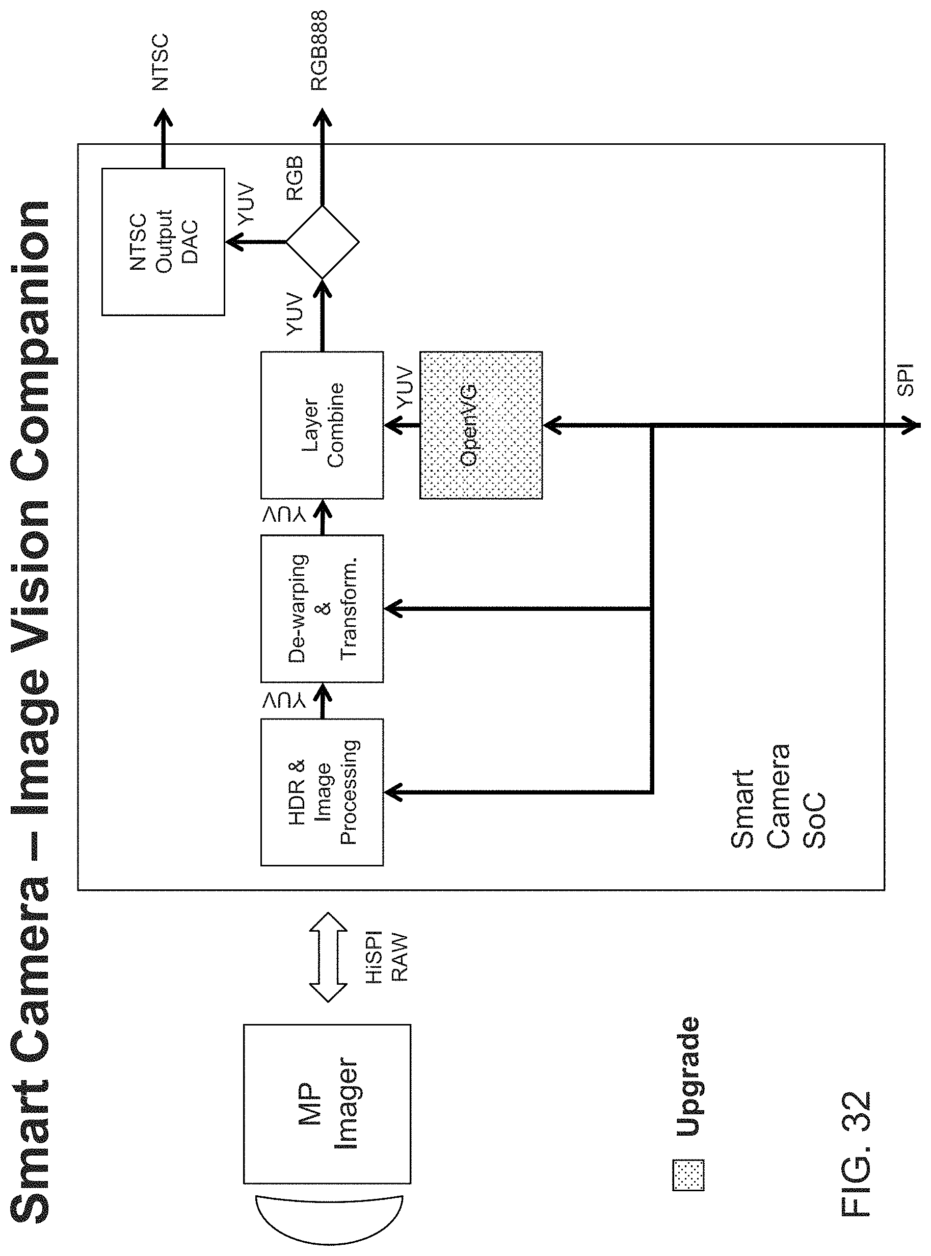
D00028

D00029

D00030

D00031

D00032

D00033

D00034

D00035

P00001

P00002

P00003

P00004

P00005

P00006

P00007

P00008

P00009

P00010

P00011

P00012

P00013

P00014

P00015

P00016

P00017

P00018

P00019

XML
uspto.report is an independent third-party trademark research tool that is not affiliated, endorsed, or sponsored by the United States Patent and Trademark Office (USPTO) or any other governmental organization. The information provided by uspto.report is based on publicly available data at the time of writing and is intended for informational purposes only.
While we strive to provide accurate and up-to-date information, we do not guarantee the accuracy, completeness, reliability, or suitability of the information displayed on this site. The use of this site is at your own risk. Any reliance you place on such information is therefore strictly at your own risk.
All official trademark data, including owner information, should be verified by visiting the official USPTO website at www.uspto.gov. This site is not intended to replace professional legal advice and should not be used as a substitute for consulting with a legal professional who is knowledgeable about trademark law.