Expandable threaded adaptor for threadless shell
Hawkins April 12, 2
U.S. patent number 11,298,640 [Application Number 16/478,092] was granted by the patent office on 2022-04-12 for expandable threaded adaptor for threadless shell. This patent grant is currently assigned to CUMMINS FILTRATION IP, INC.. The grantee listed for this patent is Cummins Filtration IP, Inc.. Invention is credited to Charles W. Hawkins.


| United States Patent | 11,298,640 |
| Hawkins | April 12, 2022 |
Expandable threaded adaptor for threadless shell
Abstract
A filter assembly comprising a housing defining an internal volume. The housing comprises a first coupling member formed in a housing first end of the housing. The housing first end is threadless. The filter assembly further comprises a filter head. The filter head comprises a first thread formed on a surface thereof. The filter assembly further comprises an adapter. The adapter comprises a second coupling member formed on an adapter first end of the adapter. The second coupling member engages the first coupling member formed in the housing first end so as to removably couple the adapter and the housing. A second thread is formed on the adapter first end. The second thread engages the first thread formed in the filter head so as to removably couple the adapter and the filter head.
| Inventors: | Hawkins; Charles W. (Sparta, TN) | ||||||||||
|---|---|---|---|---|---|---|---|---|---|---|---|
| Applicant: |
|
||||||||||
| Assignee: | CUMMINS FILTRATION IP, INC.
(Columbus, IN) |
||||||||||
| Family ID: | 62978629 | ||||||||||
| Appl. No.: | 16/478,092 | ||||||||||
| Filed: | January 19, 2018 | ||||||||||
| PCT Filed: | January 19, 2018 | ||||||||||
| PCT No.: | PCT/US2018/014401 | ||||||||||
| 371(c)(1),(2),(4) Date: | July 15, 2019 | ||||||||||
| PCT Pub. No.: | WO2018/140310 | ||||||||||
| PCT Pub. Date: | August 02, 2018 |
Prior Publication Data
| Document Identifier | Publication Date | |
|---|---|---|
| US 20190366248 A1 | Dec 5, 2019 | |
Related U.S. Patent Documents
| Application Number | Filing Date | Patent Number | Issue Date | ||
|---|---|---|---|---|---|
| 62450263 | Jan 25, 2017 | ||||
| Current U.S. Class: | 1/1 |
| Current CPC Class: | B01D 35/30 (20130101); B01D 35/306 (20130101); B01D 29/21 (20130101); B01D 2201/295 (20130101); B01D 2201/342 (20130101); B01D 2201/4092 (20130101) |
| Current International Class: | B01D 35/30 (20060101); B01D 29/21 (20060101) |
| Field of Search: | ;210/435,440-443,450,451,455 |
References Cited [Referenced By]
U.S. Patent Documents
| 2025009 | December 1935 | Baker |
| 2093877 | September 1937 | Von |
| 2270969 | January 1942 | Robinson |
| 2306325 | December 1942 | Sidney |
| 2910332 | October 1959 | Madsen |
| 2915188 | December 1959 | Buker |
| 2955028 | October 1960 | Bevans |
| 3025963 | March 1962 | Bauer |
| 3224592 | December 1965 | Burns |
| 3383841 | May 1968 | Olson |
| 3494113 | February 1970 | Corp |
| 3576095 | April 1971 | Rivers |
| 3582095 | June 1971 | Bogaert |
| 3598738 | August 1971 | Du Pont |
| 3645402 | February 1972 | Alexander et al. |
| 3687849 | August 1972 | Corp |
| 3749247 | July 1973 | Rohde |
| 4014794 | March 1977 | Lewis |
| 4061572 | December 1977 | Cohen et al. |
| 4066559 | January 1978 | Rohde |
| 4075097 | February 1978 | Paul |
| 4075098 | February 1978 | Paul et al. |
| 4080185 | March 1978 | Richter et al. |
| 4128251 | December 1978 | Gaither et al. |
| 4129429 | December 1978 | Humbert et al. |
| 4144169 | March 1979 | Grueschow |
| 4181313 | January 1980 | Hillier et al. |
| 4211543 | July 1980 | Tokar et al. |
| 4257890 | March 1981 | Hurner |
| 4300928 | November 1981 | Sugie |
| 4324213 | April 1982 | Kasting et al. |
| 4364751 | December 1982 | Copley |
| 4402912 | September 1983 | Krueger et al. |
| 4410427 | October 1983 | Wydeven |
| 4473471 | September 1984 | Robichaud et al. |
| 4572522 | February 1986 | Smagatz |
| 4589983 | May 1986 | Wydevan |
| 4600420 | July 1986 | Wydeven et al. |
| 4617122 | October 1986 | Kruse et al. |
| 4738776 | April 1988 | Brown |
| 4755289 | July 1988 | Villani |
| 4782891 | November 1988 | Cheadle et al. |
| 4826517 | May 1989 | Norman |
| 4861359 | August 1989 | Tettman |
| 4865636 | September 1989 | Raber |
| 4915831 | April 1990 | Taylor |
| 4925561 | May 1990 | Ishii et al. |
| 4951834 | August 1990 | Aikins |
| 4979969 | December 1990 | Herding |
| 5024268 | June 1991 | Cheadle et al. |
| 5050549 | September 1991 | Sturmon |
| 5069799 | December 1991 | Brownawell et al. |
| 5071456 | December 1991 | Binder et al. |
| 5094745 | March 1992 | Reynolds |
| 5120334 | June 1992 | Cooper |
| 5203994 | April 1993 | Janik |
| 5213596 | May 1993 | Kume et al. |
| 5222488 | June 1993 | Forsgren |
| 5223011 | June 1993 | Hanni |
| 5225081 | July 1993 | Brownawell |
| 5228891 | July 1993 | Adiletta |
| 5258118 | November 1993 | Gouritin et al. |
| 5298160 | March 1994 | Ayers et al. |
| 5302284 | April 1994 | Zeiner et al. |
| 5342511 | August 1994 | Brown et al. |
| 5382355 | January 1995 | Arlozynski |
| 5391212 | February 1995 | Ernst et al. |
| 5435346 | July 1995 | Tregidgo et al. |
| 5459074 | October 1995 | Muoni |
| 5472379 | December 1995 | Andress et al. |
| 5472463 | December 1995 | Herman et al. |
| 5484466 | January 1996 | Brown et al. |
| 5494497 | February 1996 | Lee |
| 5498332 | March 1996 | Handtmann |
| 5512074 | April 1996 | Hanni et al. |
| 5531848 | July 1996 | Brinda et al. |
| 5556542 | September 1996 | Berman et al. |
| 5560330 | October 1996 | Andress et al. |
| 5562825 | October 1996 | Yamada et al. |
| 5569311 | October 1996 | Oda et al. |
| 5575826 | November 1996 | Gillingham et al. |
| 5591330 | January 1997 | Lefebvre |
| 5605554 | February 1997 | Kennedy |
| 5662799 | September 1997 | Hudgens et al. |
| 5672399 | September 1997 | Kahlbaugh et al. |
| 5709722 | January 1998 | Nagai et al. |
| 5720790 | February 1998 | Kometani et al. |
| 5738785 | April 1998 | Brown et al. |
| 5753116 | May 1998 | Baumann et al. |
| 5753117 | May 1998 | Jiang |
| 5759217 | June 1998 | Joy |
| 5772883 | June 1998 | Rothman et al. |
| 5793566 | August 1998 | Scura et al. |
| 5795361 | August 1998 | Lanier et al. |
| 5803024 | September 1998 | Brown |
| 5820646 | October 1998 | Gillingham et al. |
| 5830371 | November 1998 | Smith et al. |
| 5853439 | December 1998 | Gieseke et al. |
| 5863424 | January 1999 | Lee |
| 5891402 | April 1999 | Sassa et al. |
| 5893939 | April 1999 | Rakocy et al. |
| 5902364 | May 1999 | Tokar et al. |
| 5948248 | September 1999 | Brown |
| 5985143 | November 1999 | Lin |
| 6045692 | April 2000 | Bilski et al. |
| D425189 | May 2000 | Gillingham et al. |
| 6086763 | July 2000 | Baumann |
| 6096208 | August 2000 | Connelly et al. |
| 6098575 | August 2000 | Mulshine et al. |
| 6099612 | August 2000 | Bartos |
| 6117202 | September 2000 | Wetzel |
| 6123746 | September 2000 | Alvin et al. |
| 6129852 | October 2000 | Elliott et al. |
| 6149700 | November 2000 | Morgan et al. |
| 6171355 | January 2001 | Gieseke et al. |
| 6179890 | January 2001 | Ramos et al. |
| D437402 | February 2001 | Gieseke et al. |
| 6190432 | February 2001 | Gieseke et al. |
| 6196019 | March 2001 | Higo et al. |
| 6217627 | April 2001 | Vyskocil et al. |
| 6231630 | May 2001 | Ernst et al. |
| 6235194 | May 2001 | Jousset |
| 6235195 | May 2001 | Tokar |
| 6238554 | May 2001 | Martin et al. |
| 6238561 | May 2001 | Liu et al. |
| 6261334 | July 2001 | Morgan et al. |
| 6264831 | July 2001 | Hawkins et al. |
| 6264833 | July 2001 | Reamsnyder et al. |
| RE37369 | September 2001 | Hudgens et al. |
| 6293984 | September 2001 | Oda et al. |
| 6306193 | October 2001 | Morgan et al. |
| D450828 | November 2001 | Tokar |
| 6348085 | February 2002 | Tokar et al. |
| D455826 | April 2002 | Gillingham et al. |
| 6375700 | April 2002 | Jaroszczyk et al. |
| 6379564 | April 2002 | Rohrbach et al. |
| 6391076 | May 2002 | Jaroszczyk et al. |
| 6398832 | June 2002 | Morgan et al. |
| 6402798 | June 2002 | Kallsen et al. |
| 6416561 | July 2002 | Kallsen et al. |
| 6447566 | September 2002 | Rivera et al. |
| 6475379 | November 2002 | Jousset et al. |
| 6478018 | November 2002 | Fedorowicz et al. |
| 6478019 | November 2002 | Fedorowicz et al. |
| 6478958 | November 2002 | Beard et al. |
| 6482247 | November 2002 | Jaroszczyk et al. |
| 6511599 | January 2003 | Jaroszczyk et al. |
| 6517598 | February 2003 | Anderson et al. |
| 6537453 | March 2003 | Beard et al. |
| D473637 | April 2003 | Golden |
| 6547857 | April 2003 | Gieseke et al. |
| 6554139 | April 2003 | Maxwell et al. |
| 6571962 | June 2003 | Thomas |
| 6596165 | July 2003 | Koivula |
| 6610126 | August 2003 | Xu et al. |
| 6623636 | September 2003 | Rohrbach et al. |
| 6641637 | November 2003 | Kallsen et al. |
| 6673136 | January 2004 | Gillingham et al. |
| 6676721 | January 2004 | Gillingham et al. |
| 6709588 | March 2004 | Pavlin et al. |
| 6740234 | May 2004 | Williams et al. |
| 6743317 | June 2004 | Wydeven |
| 6746518 | June 2004 | Gieseke et al. |
| 6787033 | September 2004 | Beard et al. |
| 6823996 | November 2004 | Durre |
| 6827750 | December 2004 | Drozd et al. |
| 6835304 | December 2004 | Jousset et al. |
| 6837920 | January 2005 | Gieseke et al. |
| 6843916 | January 2005 | Burrington et al. |
| 6860241 | March 2005 | Martin et al. |
| 6893571 | May 2005 | Harenbrock et al. |
| 6902598 | June 2005 | Gunderson et al. |
| 6919023 | July 2005 | Merritt et al. |
| 6922894 | August 2005 | Durre |
| 6939464 | September 2005 | Jiang et al. |
| 6953124 | October 2005 | Winter et al. |
| 6966940 | November 2005 | Krisko et al. |
| 6969461 | November 2005 | Beard et al. |
| 6984319 | January 2006 | Merritt et al. |
| 6996940 | February 2006 | Beasley |
| 6998045 | February 2006 | Durre |
| 7001450 | February 2006 | Gieseke et al. |
| 7008467 | March 2006 | Krisko et al. |
| 7018531 | March 2006 | Eilers et al. |
| 7048501 | May 2006 | Katayama et al. |
| 7070641 | July 2006 | Gunderson et al. |
| 7081145 | July 2006 | Gieseke et al. |
| 7090711 | August 2006 | Gillingham et al. |
| 7153422 | December 2006 | Herman et al. |
| 7156991 | January 2007 | Herman et al. |
| 7160451 | January 2007 | Hacker et al. |
| 7182863 | February 2007 | Eilers et al. |
| 7182864 | February 2007 | Brown et al. |
| 7211124 | May 2007 | Gieseke |
| 7217361 | May 2007 | Connor et al. |
| 7237682 | July 2007 | Reynolds et al. |
| 7247183 | July 2007 | Connor et al. |
| 7258719 | August 2007 | Miller et al. |
| 7282075 | October 2007 | Sporre et al. |
| 7311747 | December 2007 | Adamek et al. |
| 7338544 | March 2008 | Sporre et al. |
| 7344582 | March 2008 | Pearson et al. |
| 7351270 | April 2008 | Engelland et al. |
| 7396375 | July 2008 | Nepsund et al. |
| 7425226 | September 2008 | Powell |
| 7491254 | February 2009 | Krisko et al. |
| 7494017 | February 2009 | Miller |
| 7524416 | April 2009 | Bergmen |
| 7540895 | June 2009 | Furseth et al. |
| D600790 | September 2009 | Nelson et al. |
| 7582130 | September 2009 | Ng et al. |
| 7614504 | November 2009 | South et al. |
| 7625419 | December 2009 | Nelson et al. |
| 7645310 | January 2010 | Krisko et al. |
| 7655074 | February 2010 | Nepsund et al. |
| 7662216 | February 2010 | Terres et al. |
| 7674308 | March 2010 | Krisko et al. |
| 7682416 | March 2010 | Engelland et al. |
| 7731753 | June 2010 | Reo et al. |
| 7776139 | August 2010 | Schwandt et al. |
| 7799108 | September 2010 | Connor et al. |
| 7828869 | November 2010 | Parikh et al. |
| 7882961 | February 2011 | Menez et al. |
| 7931723 | April 2011 | Cuvelier |
| 7959714 | June 2011 | Smith et al. |
| 7967886 | June 2011 | Schrage et al. |
| 7972405 | July 2011 | Engelland et al. |
| 7981183 | July 2011 | Nepsund et al. |
| 7993422 | August 2011 | Krisko et al. |
| 8016903 | September 2011 | Nelson et al. |
| 8034145 | October 2011 | Boehrs et al. |
| 8043504 | October 2011 | Malgorn |
| 8048187 | November 2011 | Merritt et al. |
| 8061530 | November 2011 | Kindkeppel et al. |
| 8062399 | November 2011 | Nelson et al. |
| 8096423 | January 2012 | Menez et al. |
| 8097061 | January 2012 | Smith et al. |
| 8101003 | January 2012 | Krisko et al. |
| 8119002 | February 2012 | Schiavon et al. |
| 8146751 | April 2012 | Hawkins et al. |
| 8167966 | May 2012 | Amirkhanian et al. |
| 8177967 | May 2012 | Bagci et al. |
| 8216470 | July 2012 | Abdalla et al. |
| 8220640 | July 2012 | Schmitz et al. |
| 8241383 | August 2012 | Schrage et al. |
| 8276763 | October 2012 | Shaam |
| 8277532 | October 2012 | Reichter et al. |
| 8292983 | October 2012 | Reichter et al. |
| 8328897 | December 2012 | Nelson et al. |
| 8333890 | December 2012 | Wells et al. |
| 8348064 | January 2013 | Tandon |
| 8357219 | January 2013 | Boehrs et al. |
| 8419938 | April 2013 | Ries et al. |
| 8430657 | April 2013 | Simonelli et al. |
| 8440081 | May 2013 | Wieczorek |
| 8480779 | July 2013 | Boehrs et al. |
| 8496723 | July 2013 | Reichter et al. |
| 8501001 | August 2013 | Curt et al. |
| 8506666 | August 2013 | Haslebacher |
| 8518141 | August 2013 | Schrage et al. |
| 8544158 | October 2013 | Curt et al. |
| 8550656 | October 2013 | Mccarthy et al. |
| 8562707 | October 2013 | Nepsund et al. |
| 8636820 | January 2014 | Reichter et al. |
| 8652228 | February 2014 | Krisko et al. |
| 8709119 | April 2014 | Reichter et al. |
| 8714565 | May 2014 | Cornett et al. |
| 8753414 | June 2014 | Gebert |
| 8778043 | July 2014 | Krisko et al. |
| 8840699 | September 2014 | Bruce et al. |
| 8845897 | September 2014 | Wieczorek et al. |
| 8852308 | October 2014 | Jarrier |
| 8906128 | December 2014 | Reichter et al. |
| 8911498 | December 2014 | Bartish et al. |
| 8926725 | January 2015 | Loken et al. |
| 8932465 | January 2015 | Wells et al. |
| 9101883 | August 2015 | Pugh et al. |
| 9114346 | August 2015 | Schrage et al. |
| 9211488 | December 2015 | South et al. |
| 9308476 | April 2016 | Martin et al. |
| 9320997 | April 2016 | Campbell et al. |
| 9409107 | August 2016 | Arakeri et al. |
| 9415333 | August 2016 | Kindkeppel et al. |
| 9782706 | October 2017 | Levy |
| 9782708 | October 2017 | Kindkeppel et al. |
| 10729999 | August 2020 | Nichols et al. |
| 10744443 | August 2020 | Silvestro |
| 10835852 | November 2020 | Decoster et al. |
| 2001/0032545 | October 2001 | Goto et al. |
| 2002/0046556 | April 2002 | Reid |
| 2002/0060178 | May 2002 | Tsabari |
| 2002/0073850 | June 2002 | Tokar et al. |
| 2002/0096247 | July 2002 | Wydeven |
| 2002/0157359 | October 2002 | Stenersen et al. |
| 2002/0170280 | November 2002 | Soh |
| 2002/0185007 | December 2002 | Xu et al. |
| 2002/0185454 | December 2002 | Beard et al. |
| 2002/0195384 | December 2002 | Rohrbach et al. |
| 2003/0121845 | July 2003 | Wagner et al. |
| 2003/0154863 | August 2003 | Tokar et al. |
| 2003/0184025 | October 2003 | Matsuki |
| 2003/0218150 | November 2003 | Blakemore et al. |
| 2004/0035097 | February 2004 | Schlensker et al. |
| 2004/0040271 | March 2004 | Kopec et al. |
| 2004/0060861 | April 2004 | Winter et al. |
| 2004/0091652 | May 2004 | Kikuchi et al. |
| 2004/0091654 | May 2004 | Kelly et al. |
| 2004/0140255 | July 2004 | Merritt et al. |
| 2004/0173097 | September 2004 | Engelland et al. |
| 2004/0187689 | September 2004 | Sporre et al. |
| 2004/0221555 | November 2004 | Engelland et al. |
| 2004/0226443 | November 2004 | Gillingham et al. |
| 2005/0019236 | January 2005 | Martin et al. |
| 2005/0024061 | February 2005 | Cox et al. |
| 2005/0166561 | August 2005 | Schrage et al. |
| 2005/0173325 | August 2005 | Klein et al. |
| 2005/0178714 | August 2005 | Stockbower |
| 2005/0193695 | September 2005 | Holmes et al. |
| 2005/0194312 | September 2005 | Niemeyer et al. |
| 2005/0224061 | October 2005 | Ulrich et al. |
| 2005/0252848 | November 2005 | Miller |
| 2006/0064956 | March 2006 | Connor et al. |
| 2006/0113233 | June 2006 | Merritt et al. |
| 2006/0118474 | June 2006 | Kolczyk et al. |
| 2006/0180537 | August 2006 | Loftis et al. |
| 2006/0213139 | September 2006 | Stramandinoli |
| 2007/0037428 | February 2007 | Annecke |
| 2007/0095744 | May 2007 | Bagci et al. |
| 2007/0175815 | August 2007 | Thomas |
| 2007/0240392 | October 2007 | Ng et al. |
| 2007/0261374 | November 2007 | Nelson et al. |
| 2007/0267338 | November 2007 | Menez et al. |
| 2008/0011672 | January 2008 | Schwartz et al. |
| 2008/0022641 | January 2008 | Engelland et al. |
| 2008/0035587 | February 2008 | Wieczorek et al. |
| 2008/0047132 | February 2008 | Wieczorek |
| 2008/0087589 | April 2008 | Grzonka et al. |
| 2008/0107765 | May 2008 | Considine et al. |
| 2008/0110142 | May 2008 | Nelson et al. |
| 2008/0179263 | July 2008 | Wieczorek et al. |
| 2008/0237113 | October 2008 | Jensen |
| 2008/0250766 | October 2008 | Schrage et al. |
| 2008/0307759 | December 2008 | Reichter et al. |
| 2008/0308481 | December 2008 | Wieczorek et al. |
| 2009/0014381 | January 2009 | South et al. |
| 2009/0026124 | January 2009 | Schmitz et al. |
| 2009/0050554 | February 2009 | Shaam |
| 2009/0057213 | March 2009 | Schiavon et al. |
| 2009/0057219 | March 2009 | Bagci et al. |
| 2009/0064646 | March 2009 | Reichter et al. |
| 2009/0071892 | March 2009 | Malgorn |
| 2009/0090669 | April 2009 | Holzmann et al. |
| 2009/0095669 | April 2009 | South |
| 2009/0126324 | May 2009 | Smith et al. |
| 2009/0135590 | May 2009 | Mccarthy et al. |
| 2009/0151311 | June 2009 | Reichter et al. |
| 2009/0193972 | August 2009 | Schwandt et al. |
| 2009/0241315 | October 2009 | Menez et al. |
| 2009/0242475 | October 2009 | Menez et al. |
| 2009/0249754 | October 2009 | Amirkhanian et al. |
| 2009/0326657 | December 2009 | Grinberg et al. |
| 2010/0001477 | January 2010 | Eyers et al. |
| 2010/0043366 | February 2010 | Boehrs et al. |
| 2010/0051528 | March 2010 | Derstler et al. |
| 2010/0064646 | March 2010 | Smith et al. |
| 2010/0065203 | March 2010 | Tanbour et al. |
| 2010/0077710 | April 2010 | Severance et al. |
| 2010/0101993 | April 2010 | Wells et al. |
| 2010/0108590 | May 2010 | Curt et al. |
| 2010/0114318 | May 2010 | Gittings et al. |
| 2010/0126919 | May 2010 | Hawkins et al. |
| 2010/0150764 | June 2010 | Simonelli et al. |
| 2010/0170209 | July 2010 | Nelson et al. |
| 2010/0176047 | July 2010 | Bagci et al. |
| 2010/0186353 | July 2010 | Ackermann et al. |
| 2010/0200490 | August 2010 | Martin et al. |
| 2010/0258493 | October 2010 | Kindkeppel et al. |
| 2010/0263339 | October 2010 | Steins et al. |
| 2010/0294707 | November 2010 | Abdalla et al. |
| 2010/0294712 | November 2010 | Abdalla et al. |
| 2011/0089104 | April 2011 | Menez et al. |
| 2011/0132829 | June 2011 | Tucker |
| 2011/0197556 | August 2011 | Brown et al. |
| 2011/0203099 | August 2011 | Curt et al. |
| 2011/0260413 | October 2011 | Voltenburg et al. |
| 2011/0303604 | December 2011 | McKenzie |
| 2012/0031059 | February 2012 | Haslebacher |
| 2012/0055127 | March 2012 | Holzmann et al. |
| 2012/0061307 | March 2012 | Kindkeppel et al. |
| 2012/0223008 | September 2012 | Mbadinga-Mouanda et al. |
| 2013/0015119 | January 2013 | Pugh et al. |
| 2013/0087497 | April 2013 | Wells et al. |
| 2013/0220914 | August 2013 | Hawkins et al. |
| 2013/0291502 | November 2013 | Gorman |
| 2013/0327696 | December 2013 | Bagci et al. |
| 2014/0027366 | January 2014 | Hawkins et al. |
| 2014/0034565 | February 2014 | Loken et al. |
| 2014/0034566 | February 2014 | Verdegan et al. |
| 2014/0048468 | February 2014 | Kindkeppel et al. |
| 2014/0071669 | March 2014 | Mccarthy et al. |
| 2014/0096493 | April 2014 | Kelmartin et al. |
| 2014/0151275 | June 2014 | Bradford et al. |
| 2014/0190880 | July 2014 | Krull |
| 2014/0251895 | September 2014 | Wagner |
| 2014/0260143 | September 2014 | Kaiser |
| 2014/0290194 | October 2014 | Muenkel et al. |
| 2014/0318090 | October 2014 | Rieger et al. |
| 2015/0013289 | January 2015 | Hasenfratz et al. |
| 2015/0013293 | January 2015 | Wagner et al. |
| 2015/0033684 | February 2015 | Pettersson |
| 2015/0060351 | March 2015 | Kaufmann et al. |
| 2015/0061307 | March 2015 | Nakanishi |
| 2015/0090651 | April 2015 | Kotale |
| 2015/0096273 | April 2015 | Kaiser |
| 2015/0096932 | April 2015 | Hou et al. |
| 2015/0176544 | June 2015 | Kaufmann et al. |
| 2015/0202556 | July 2015 | Hawkins et al. |
| 2015/0231532 | August 2015 | Pugh et al. |
| 2015/0285381 | October 2015 | Preston et al. |
| 2016/0023142 | January 2016 | Arakeri et al. |
| 2016/0045848 | February 2016 | Campbell et al. |
| 2016/0059172 | March 2016 | Allott et al. |
| 2016/0082372 | March 2016 | South et al. |
| 2016/0160816 | June 2016 | Venkatraman et al. |
| 2016/0169391 | June 2016 | Emig et al. |
| 2016/0222931 | August 2016 | Jiang et al. |
| 2016/0228798 | August 2016 | Page et al. |
| 2016/0258397 | September 2016 | Jiang et al. |
| 2016/0332103 | November 2016 | Marks et al. |
| 2017/0078852 | March 2017 | Tan et al. |
| 2018/0318745 | November 2018 | Nichols et al. |
| 2020/0324237 | October 2020 | Moers et al. |
| 1130539 | Sep 1996 | CN | |||
| 1139884 | Jan 1997 | CN | |||
| 1193288 | Sep 1998 | CN | |||
| 2296402 | Nov 1998 | CN | |||
| 1486213 | Mar 2004 | CN | |||
| 1590746 | Mar 2005 | CN | |||
| 2372041 | Apr 2005 | CN | |||
| 1754612 | Apr 2006 | CN | |||
| 101084050 | Dec 2007 | CN | |||
| 101374582 | Feb 2009 | CN | |||
| 201292900 | Aug 2009 | CN | |||
| 101695616 | Apr 2010 | CN | |||
| 201696412 | Jan 2011 | CN | |||
| 102083510 | Jun 2011 | CN | |||
| 102271780 | Dec 2011 | CN | |||
| 202746046 | Feb 2013 | CN | |||
| 103977647 | Aug 2014 | CN | |||
| 104220142 | Dec 2014 | CN | |||
| 105688498 | Jun 2016 | CN | |||
| 106102858 | Nov 2016 | CN | |||
| 202040173 | Nov 2020 | CN | |||
| 88 08 632 | Sep 1988 | DE | |||
| 29613098 | Sep 1996 | DE | |||
| 10 2008 062 956 | Jun 2010 | DE | |||
| 0 718 021 | Jun 1996 | EP | |||
| 0 747 579 | Dec 1996 | EP | |||
| 0 982 062 | Mar 2000 | EP | |||
| 1 129 760 | Sep 2001 | EP | |||
| 1 166 843 | Jan 2002 | EP | |||
| 1 208 902 | May 2002 | EP | |||
| 1 233 173 | Aug 2002 | EP | |||
| 1 693 096 | Aug 2006 | EP | |||
| 1 693 096 | Aug 2006 | EP | |||
| 1 747 053 | Jan 2007 | EP | |||
| 3 370 849 | Sep 2018 | EP | |||
| 2214505 | Aug 1974 | FR | |||
| 0 970 826 | Sep 1964 | GB | |||
| 2 082 932 | Mar 1982 | GB | |||
| 2 404 348 | Feb 2005 | GB | |||
| 60-112320 | Jun 1985 | JP | |||
| 01-163408 | Jun 1989 | JP | |||
| 01-171615 | Jul 1989 | JP | |||
| 02-025009 | Jan 1990 | JP | |||
| WO-00/50152 | Aug 2000 | WO | |||
| WO-00/74818 | Dec 2000 | WO | |||
| WO-01/05485 | Jan 2001 | WO | |||
| WO-2004/054684 | Jul 2004 | WO | |||
| WO-2005/058461 | Jun 2005 | WO | |||
| WO-2005/077487 | Aug 2005 | WO | |||
| WO-2006/093981 | Sep 2006 | WO | |||
| WO-2007/009039 | Jan 2007 | WO | |||
| WO-2007/089662 | Aug 2007 | WO | |||
| WO-2012/153430 | Nov 2012 | WO | |||
| WO-2017/079191 | May 2017 | WO | |||
| WO 2017/120113 | Jul 2017 | WO | |||
Other References
|
International Preliminary Report on Patentability on PCT/US2018/014401 dated Jul. 30, 2019. cited by applicant . International Preliminary Report on Patentability on PCT/US2018/018724 dated Aug. 27, 2019. cited by applicant . International Search Report on PCT/IB2019/056208 dated Nov. 21, 2019. cited by applicant . International Search Report and Written Opinion issued for PCT/US2018/014401, dated May 15, 2018, 18 pages. cited by applicant . International Search Report and Written Opinion issued for PCT/US2018/018724, dated Apr. 24, 2018, 13 pages. cited by applicant . Akro-Mils, "Nest & Stack Totes," retrieved from http://web.archive.org/web/20150323114331/https://akro-mils.com/produts/t- ypes/plastic-storage-containers/nest-stack-totes, 1 page (2015). cited by applicant . First Examination Report for Indian Patent App. No. 202047056950 dated Mar. 24, 2021, 5 pages. cited by applicant . First Examination Report for Indian Patent App. No. 3035/KOLNP/2011, dated Feb. 8, 2019, 7 pages. cited by applicant . First Office Action for Chinese Patent App. No. 201080004417.5, dated May 24, 2013, 13 pages (with translation). cited by applicant . First Office Action for Chinese Patent App. No. 2016800710703 dated Nov. 26, 2019, 29 pages (with translation). cited by applicant . First Office Action for Chinese Patent App. No. 201880012627.5 dated Dec. 12, 2020, 22 pages (with English translation). cited by applicant . First Office Action for Chinese Patent Application No. 201880007980.4 dated Jan. 12, 2021, 15 pages (with English translation). cited by applicant . First Office Action issued for Chinese Patent Application No. CN201880018033.5 dated Dec. 24, 2020, 10 pages. cited by applicant . International Search Report & Written Opinion for PCT/US2010/024765 dated Apr. 7, 2010, 9 pages. cited by applicant . International Search Report and Written Opinion for PCT/US2016/063053, dated Feb. 16, 2017, 8 pages. cited by applicant . International Search Report and Written Opinion for PCT/US2017/021615, dated Jun. 6, 2017, 8 pages. cited by applicant . International Search Report and Written Opinion for PCT/US2017/030386, dated Jul. 26, 2017, 9 pages. cited by applicant . International Search Report and Written Opinion for PCT/US2018/018696, dated Apr. 19, 2018, 8 pages. cited by applicant . Non-Final Office Action on U.S. Appl. No. 16/487,209 dated May 28, 2021. cited by applicant . Office Action for German Patent App. No. 11 2010 001 567.8 dated May 18, 2017, 12 pages (with translation). cited by applicant . Second Office Action for Chinese Patent App. No. 201080004417.5, dated Mar. 5, 2014, 28 pages (with translation). cited by applicant . Office Action issued for Chinese Patent Application No. CN 201880007980.4 dated Jul. 9, 2021, 7 pages. cited by applicant. |
Primary Examiner: Gonzalez; Madeline
Attorney, Agent or Firm: Foley & Lardner LLP
Parent Case Text
CROSS REFERENCE TO RELATED APPLICATIONS
The present application is a national stage of PCT Application No. PCT/US2018/014401, filed Jan. 19, 2018 which claims priority to U.S. Provisional Patent Application No. 62/450,263, filed Jan. 25, 2017. The contents of both applications are incorporated herein by reference in their entirely and for all purposes.
Claims
What is claimed is:
1. A filter assembly, comprising: a housing defining an internal volume, the housing comprising a first coupling member formed on an outer surface on a housing first end of the housing, the housing first end being threadless; a filter head comprising a first thread formed on a surface thereof; and an adapter comprising: a second coupling member formed on an internal surface on an adapter first end of the adapter, the second coupling member engaging the first coupling member formed in the housing first end so as to removably couple the adapter and the housing; a second thread formed on an external surface on the adapter first end, the second thread engaging the first thread formed in the filter head so as to removably couple the adapter and the filter head; and a segmented section formed on the adapter first end, the segmented section including the second coupling member, the segmented section allowing for flex in the adapter first end to expand to a larger diameter to receive the housing, wherein rotation of the adapter into the filter head compresses the segmented section into the housing.
2. The filter assembly of claim 1, wherein the first thread is formed on an internal surface of the filter head.
3. The filter assembly of claim 1, wherein the second coupling member comprises one of a protrusion and a detent, and wherein the first coupling member comprises the other of the protrusion and the detent.
4. The filter assembly of claim 1, wherein the second thread is a buttress thread.
5. The filter assembly of claim 1, further comprising: a filter element positioned within the internal volume of the housing, the filter element comprising: filter media; and a first end cap coupled to a filter media first end of the filter media, the first end cap comprising: a base, and a first end cap flange positioned about a periphery of the base, the first end cap flange extending from the base away from the filter element; and a first end sealing member positioned between an outer surface of the first end cap flange and an inner surface of the housing first end, the first end sealing member forming a seal between the housing and the first end cap.
6. The filter assembly of claim 1, wherein the adapter is permanently connected to the housing.
7. An adapter for a separator filter assembly, comprising: an adapter body; a first coupling member formed on an adapter first end of the adapter body, the first coupling member configured to engage a second coupling member formed on an outer surface of a housing first end of a housing so as to removably couple the adapter and the housing; a third coupling member formed on an external surface of the adapter first end, the third coupling member configured to engage a fourth coupling member formed in a filter head so as to removably couple the adapter and the filter head; and a plurality of segmented sections extending around the adapter first end, the plurality of segmented sections allowing for flex in the adapter to receive the housing, the plurality of segmented sections comprising a portion of the first coupling member and a portion of the third coupling member.
8. The adapter of claim 7, wherein the first coupling member formed on the adapter first end comprises a protrusion that is formed on an internal surface on the adapter first end.
9. The adapter of claim 7, wherein the third coupling member and the fourth coupling member each comprise a threaded coupling member.
10. The adapter of claim 7, wherein the third coupling member formed on the adapter first end is disposed radially along an outside circumferential surface of the adapter.
11. The adapter of claim 7, wherein the first coupling member formed on the adapter first end is disposed radially along an inside circumferential surface of the adapter.
12. The adapter of claim 7, further comprising: a plurality of indentations formed on an outer surface of the adapter, the plurality of indentions being axial indentations defined circumferentially about adapter, the plurality of indentations facilitating gripping for coupling and/or uncoupling of the adapter by a user.
13. The adapter of claim 7, further comprising an outer flange extending circumferentially along an outside surface of the adapter, the third coupling member separated from a plurality of indentations by the outer flange.
14. The filter assembly of claim 1, wherein a portion of the second coupling member extends radially inward from the segmented section.
15. The filter assembly of claim 1, wherein a portion of the second thread extends radially outward from the segmented section.
16. The filter assembly of claim 5, wherein the filter element further comprises an inner sealing member coupled to the first end cap and positioned radially inward from the first end sealing member.
17. The filter assembly of claim 16, wherein the first end sealing member and the inner sealing member are engaged with the filter head so as to form a sealing engagement.
18. The filter assembly of claim 17, wherein the filter head further comprises a circumferential groove structured to receive at least a portion of the first end sealing member such that the first end sealing member forms a sealing engagement with the circumferential groove.
19. The adapter of claim 7, wherein rotation of the adapter into the filter head compresses the plurality of segmented sections into the housing.
Description
TECHNICAL FIELD
The present application relates generally to fluid filtration systems. More particularly, the present application relates to fuel water separator filter assemblies.
BACKGROUND
Internal combustion engines generally combust a mixture of fuel (e.g., diesel, gasoline, natural gas, etc.) and air. Prior to entering the engine, the fuel is typically passed through a filter element to remove particulate matter (e.g., dust, metal particles, debris, etc.) from the fuel prior to combustion. Similarly, lubricant or lube (e.g., engine oil) provided to the engine may also be passed through a filter element so as to remove particulate matter from the lube before communicating to the engine. The fuel or oil may include water, which may accumulate in the filter and may have to be removed.
Various filter assemblies generally comprise a nut plate positioned on an end of a housing of the filter assembly, with such nut plates providing a mechanism for coupling of a filter head to a first end of the housing of the filter assembly, or coupling of a cover or bowl to a second end of the filter housing. Such nut plates introduce additional parts into the filter assembly and may increase manufacturing complexity and manufacturing cost of such filters. Additionally, the filter is configured for a rotatable and detachable connection to the head and/or bowl, by way of threaded connections. Due to this direct connection, the filter typically must be of a certain type and/or size in order to reliably connect to the head and/or bowl. Consequently, larger shell diameters and increases in wall thickness can prove to be very challenging for the shell suppliers to adapt to, and the alternate design option of roll threading to accommodate these changes is expensive.
SUMMARY
Various embodiments provide for a filter assembly comprising a housing defining an internal volume. The housing comprises a first coupling member formed in a housing first end of the housing. The housing first end is threadless. The filter assembly further comprises a filter head. The filter head comprises a first thread formed on a surface thereof. The filter assembly further comprises an adapter. The adapter comprises a second coupling member formed on an adapter first end of the adapter. The second coupling member engages the first coupling member formed in the housing first end so as to removably couple the adapter and the housing. A second thread is formed on the adapter first end. The second thread engages the first thread formed in the filter head so as to removably couple the adapter and the filter head.
Further embodiments provide for an adapter for a separator filter assembly (such as a fuel water separator filter assembly). The adapter comprises a first coupling member formed on an adapter first end of the adapter body. The first coupling member is configured to engage a second coupling member formed in a housing first end of a housing so as to removably couple the adapter and the housing. A third coupling member is formed on the adapter first end. The third coupling member is configured to engage a fourth coupling member formed in a filter head so as to removably couple the adapter and the filter head.
These and other features, together with the organization and manner of operation thereof, will become apparent from the following detailed description when taken in conjunction with the accompanying drawings, wherein like elements have like numerals throughout the several drawings described below.
BRIEF DESCRIPTION OF THE DRAWINGS
FIG. 1A is an exploded perspective view of a filter assembly, according to an example embodiment.
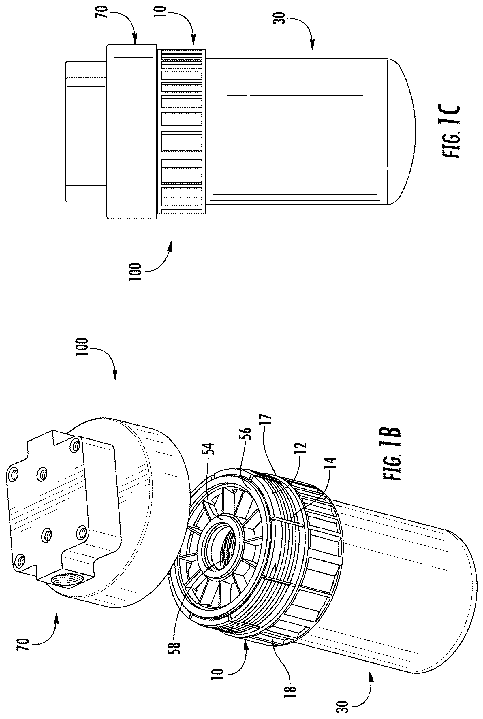
FIG. 1B is an assembled perspective view with a detached filter head of the filter assembly of FIG. 1A.
FIG. 1C is a front plan view with an attached filter head of a filter assembly.
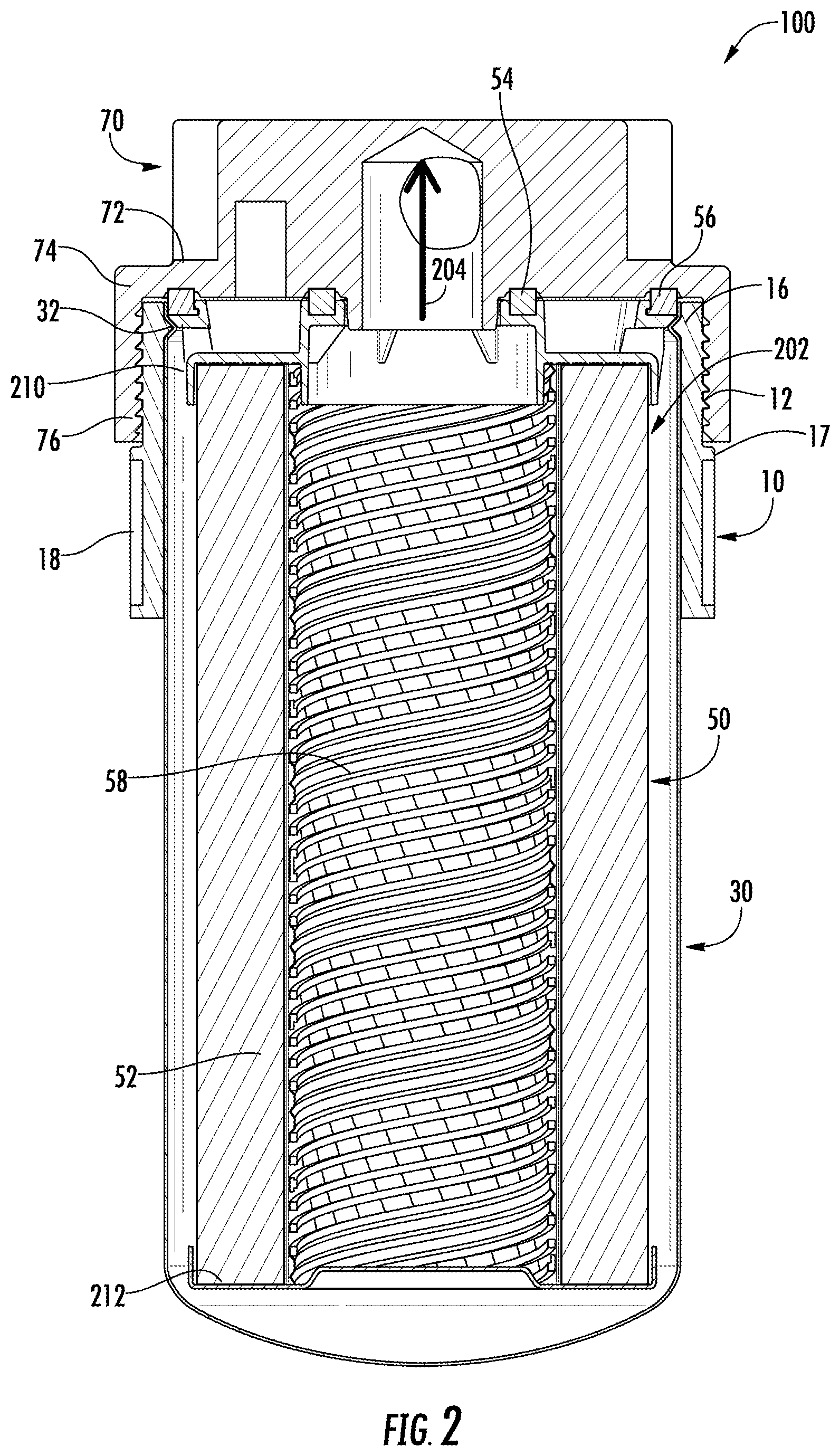
FIG. 2 is a cross-sectional view of the assembled filter assembly of FIG. 1C.
FIG. 3 is a partial cross-sectional exploded view of a section of the filter assembly of FIG. 2.
DETAILED DESCRIPTION OF VARIOUS EMBODIMENTS
Embodiments described herein relate generally to a system and method for securing a housing to a filter head without the use of a threaded connection. Generally, the housing has at least one detent (e.g., protrusion) feature formed in a top or first end of the housing, a filter head, having a first thread formed on an internal surface of the filter head; and an adapter configured to be removably coupled to the housing and the filter head.
Embodiments of the filter assembly described herein comprise an adapter that includes an interior facing coupling member for securing a housing and an exterior facing coupling member to a filter head without the use of a threaded connection directly between the housing and the filter head. The adapter can include both male and female coupling members may provide benefits including, for example: (1) allowing direct coupling of a housing to a threaded filter head, thereby allowing any housing to be used in a spin-on filtration system; (2) providing at least one segmented section which allow for flex in the structure of the adapter, thereby easing housing installation in the adapter and allowing for a plurality of coupling members to be used (e.g., snap fit, detent fit, etc.); (3) a secure sealing surface between the filter head and adapter; (4) applying a vertical load on the sealing gaskets without the addition of the torsional twist commonly present with spin on products when the adapter is engaged with the housing; and (5) reducing a manufacturing cost of assembly of the filter assembly by reducing the number of parts included in the filter assembly and allowing flexibility in the usable housing types.
FIG. 1A is an exploded perspective view of a filter assembly 100. FIG. 1B is an assembled perspective view of the filter assembly 100 with a detached filter head. FIG. 1C is a front plan view of a filter assembly 100 with an attached filter head. The filter assembly 100 comprises a housing 30, a filter element 50, an adapter 10, and a filter head 70. In the embodiment shown in FIGS. 1A-C, the filter assembly 100 is a fuel filter for the filtration of fuel. However, the filter assembly 100 is not limited to the filtration of fuel and may be used for the filtration of other fluids, such as lube, oil, air, or the like. For example, the filter assembly 100 may be configured to remove water contained in a fuel, such as a diesel fuel, before the fuel is introduced into an engine, such as a diesel engine. In addition, the filter assembly 100 is not limited to a fuel water separator filter and may be alternatively configured to function as different types of filters, including, but not limited to, suction side filters.
The filter head 70 includes a fluid inlet, which allows a fluid to be filtered to flow into the filter element 50, and a fluid outlet, which allows a filtered fluid to flow out of the filter element 50. The filter head 70 includes a filter head base 72 and a filter head sidewall 74 extending from an outer periphery of the filter head base 72. The filter head sidewall 74 extends from an outer periphery of the filter head base 72 towards the housing 30. The filter head 70 has first thread 76 on an inner surface of the filter head sidewall 74. The first thread 76 is structured to removably engage a second thread 12 of the adapter 10, so as to be coupled to a first end 20 of the adapter 10.
The filter element 50 may comprise a spin-on filter that includes a housing 30 and a filter element 50. In some embodiments, the filter element 50 is permanently affixed or installed within the housing 30. The filter element 50 includes a filter media 52 that is configured to filter the fluid. The filter media 52 comprises a porous material having a predetermined pore size and is configured to filter particulate matter from a fluid such as air flowing therethrough. The filter media 52 may comprise pleated media, corrugated media, fluted media, or the like. Disposed within the center of the filter media 52 may be a center tube 58. The center tube 58 may be configured to support the filter media 52 and/or allow the flow of fluid through the filter media 52. The center tube 58 may comprise a plurality of apertures so as to allow the fluid (e.g., air, fuel, oil etc.) to flow into the filter channel after passing through the filter media 52. The center tube 58 may be formed from plastic, metals or any other suitable material.
The filter element 50 includes an inner sealing member 54 and an outer sealing member 56 to provide a radial seal with the filter head 70 and/or the adapter 10. In some embodiments, the seal formed by the inner sealing member 54 and the outer sealing member 56 may comprise a "leak-tight" seal or a "substantially" leak-tight seal. As used herein, the term "leak-tight" is understood to encompass both a hermetic seal (i.e., a seal that is gas-impervious) as well as a seal that is liquid-impervious. The term "substantially" when used in connection with "leak-tight" is intended to convey that, while total fluid imperviousness is desirable, some minimal leakage due to manufacturing tolerances, or other practical considerations (such as, for example, the pressure applied to the seal and/or within the fluid), can occur even in a "substantially leak-tight" seal. In some arrangements, one or both of the inner sealing member 54 and the outer sealing member 56 may comprise O-rings.
The housing 30 defines an internal volume within which the filter element 50 is positioned. The housing 30 may be formed from a strong and rigid material, for example plastics (e.g., polypropylene, high density polyethylene, polyvinyl chloride, etc.), metals (e.g., aluminum, stainless steel, etc.), or any other suitable material. In particular embodiments, the housing 30 may comprise a cylindrical housing having generally a circular cross-sectional. In other embodiments, the housing 30 may have any suitable shape, for example square, rectangular, polygonal, etc.
The housing 30 comprises a housing first end 34 and a housing second end 36. The housing first end 34 comprises first coupling member 32 on an outer surface thereof. In some arrangements, the first coupling member 32 comprises a female end to a male-female coupling member pair, configured to receive a corresponding male coupling member (e.g., the second coupling member 16) of the adapter. As used herein, "housing first end" 34 is intended to refer to the area that comprises about twenty percent of the axial distance starting from the boundary that forms the top of the housing 30 member towards the boundary that forms the bottom of the housing 30. As used herein, "housing second end" 36 is intended to refer to the area that comprises about twenty percent of the axial distance starting from the boundary that corresponds to the bottom of the housing 30 member towards the boundary that corresponds to the top of the housing 30.
As shown in FIG. 1A, the first coupling member 32 comprises a detent element. In some arrangements, the first coupling member 32 is stamped into the housing 30. In other arrangements, the first coupling member 32 may be molded or otherwise formed into a sidewall of the housing 30. The first coupling member 32 is structured to removably engage a second coupling member 16 of the adapter 10, so as to be coupled to the first end 20 of the adapter 10.
The adapter 10 is configured to couple the housing 30 to the filter head 70 and filter element 50. The adapter 10 comprises the second thread 12 disposed externally on the first end 20, at least one segmented section 14 on the first end 20, second coupling member 16 disposed internally on the first end 20, an outer flange 17 extending radially outward from the adaptor 10, and a plurality of indentations 18 disposed externally on a second end 22. The outer flange 17 is interposed between the second thread 12 and the plurality of indentations 18. In some arrangements, the second coupling member 16 comprises a male coupling member of a male-female coupling member pair, configured to receive a corresponding female coupling member (e.g., the first coupling member 32) of the housing.
Generally, the adapter 10 first receives a housing 30, whereby the adapter 10 is positioned circumferentially around the housing first end 34 of the housing. The filter head 70 receives the adapter 10, whereby the filter head 70 is circumferentially around the first end 20 of the adapter 10. Upon installation of the adapter 10 into the filter head 70, the filter head 70, adapter 10, housing 30, and filter element 50 are all removably coupled and form a "leak-tight" seal in various locations to facilitate the intake, filtering, and outflow of a fluid. As will be appreciated, the adapter 10 can be re-used with multiple different housings 30 (e.g., during filter servicing, the adapter 10 can be removed from a used housing 30, the used housing 30 is discarded, and the adapter 10 reattached to a new housing 30 having the mating member to the coupling member 32). The adapter 10 may be formed from a strong and rigid material, for example plastics (e.g., polypropylene, high density polyethylene, polyvinyl chloride, etc.), metals (e.g., aluminum, stainless steel, etc.), or any other suitable material
The at least one segmented section 14 is structured to allow flex in the first end 20 of the adapter 10 to facilitate coupling with the housing 30. The segmented section 14 allows for the adapter 10 to be inserted onto the housing 30 and provide the second coupling member 16 of the adapter 10 to the first coupling member 32 of the housing 30. The segmented section 14 may be radially disposed on the first end of the adapter 10. In some arrangements, the segmented section 14 includes eight segmented sections to provide greater flex and ease of installation over the housing 30
The second coupling member 16 comprises an internally facing coupling member disposed on the first end 20 (e.g., on an internal wall) and structured to couple with the first coupling member 32 of the housing 30. In addition, the second coupling member 16 extends radially inward. The second coupling member 16 may be formed during a deep draw machining process used to form the adapter 10. In some arrangements, the second coupling member 16 includes a male detent element. The connection between the adapter 10 and the housing 30, however, is not particularly limited to a detent element and may be any other appropriate detachable connections, such as a snap-fit connection or the like. As will be appreciated, when the expandable adapter 10 attaches to the housing 30 a vertical load is applied on the inner sealing member 54 and the outer sealing member 56 without the addition of the torsional twist commonly present--and required--with spin-on filter assemblies.
The second thread 12 comprises an externally facing thread disposed on the first end 20 (e.g., on an outer wall) and structured to engage with the first thread 76 of the filter head 70. In addition, the second thread 12 extends radially outward. In some arrangements, the threaded design is that of a buttress design, whereby the threads are positivity fixed by the threads disposed on the filter head 70. In those arrangements, there is no possibility of expansion of the threads and/or the adapter 10 that would loosen or reduce the force applied to the sealing members (e.g., gaskets). The second thread 12 may be formed during a deep draw machining process used to form the adapter 10. In some arrangements, the second thread 12 includes two threads per turn. The connection between the adapter 10 and the filter head 70, however, is not particularly limited to a threaded connection and may be any other appropriate detachable connections, such as a snap-fit connection or the like. The second thread 12 is separated from the plurality of indentations 18 by the outer flange 17.
A plurality of indentations 18 or depressions may be formed on an outer surface of the adapter second end 22. For example, the plurality of indentations 18 may comprise axial indentations defined circumferentially about the adapter second end 22. The plurality of indentations 18 may be positioned with any suitable spacing between each adjacent indentation (i.e., any positioned at any suitable pitch). The plurality of indentations 18 may serve to facilitate gripping of the housing 30 for coupling and/or uncoupling the housing, for example to a filter head 70.
Referring to FIG. 1B, an assembled perspective view with a detached filter head 70 of the filter assembly 100 of FIG. 1A is shown. To install the adapter 10, the filter element 50 is first disposed in the housing 30 and secured within the housing, for example, through threaded, welded, or snap-fit connections. The housing 30--now comprising the filter element 50 in the internal volume of the housing 30--is then inserted into the adapter 10 such that the second coupling member 16 of the adapter 10 is disposed in the first coupling member 32 of the housing 30. The segmented section 14 of the adapter 10 allows for flex and aids in easing the installation of the adapter 10 over the housing 30. In some embodiments, the adapter 10 may be smaller (e.g. smaller in radius) than the housing 30. In those embodiments, the installation may be reversed, such that the adapter 10 is inserted into the housing 30 such that the second coupling member 16 of the adapter 10 is disposed in the first coupling member 32 of the housing 30.
Referring to FIG. 1C, an assembled front plan view of the filter assembly 100 of FIG. 1A is shown. To engage the adapter 10--now removably coupled to the filter element 50 and the housing 30--the adapter 10 is engaged with the filter head 70. The installation includes rotating the adapter 10 such that the first thread 76 of the filter head 70 is rotationally coupled with the second thread 12 of the adapter 10. As will be appreciated, the rotation of the adapter 10 into the filter head 70, compresses the segmented section 14 and the first end 20 of the adapter 10, thereby tightening the coupling of the second coupling member 16 of the adapter 10 disposed in the first coupling member 32 of the housing 30. Upon installation of the adapter 10 in the filter head 70, the various features coupled together are substantially flush with each other and can comprise a leak-tight" seal. As will be appreciated, when the adapter 10 is attached to the filter head 70, a vertical load is applied on the inner sealing member 54 and the outer sealing member 56 without the addition of the torsional twist. In some embodiments, the adapter 10 is larger (e.g., larger in radius) than the filter head 70. In those embodiments, the installation may be different, such that the adapter 10 is raised to the filter head 70, causing the filter head 70 be inserted into the adapter 10, and the adapter 10 is rotated such that the first thread 76 of the filter head 70 is rotationally coupled with the second thread 12 of the adapter 10.
Referring to FIG. 2, a cross-sectional view of the assembled filter assembly of FIG. 1C is shown. As shown, the various features coupled together are substantially flush with each other and comprise a leak-tight" seal. For example, the filter head 70 and adapter 10 are substantially flush via the thread coupling 12, 76 (e.g., male-female thread coupling). The adapter 10 and the housing 30 are substantially flush via the coupling members connection. The inner sealing member 54 and the outer sealing member 56 of the filter element 50 are sealably connected and flush with the filter head 70. The filter element 50 is securely disposed in the housing 30 through a first (e.g. top) end cap 210 and a second (e.g., bottom) end cap 212. In operation, the fluid flows into the filter head 70 through an inlet (not shown) and flows into 202 the housing 30. The fluid is filtered by the filter media 52 and travels radially through the filter media 52 into the center tube 58. The filtered fluid travels axially through the center tube 58 and flows out 204 of an outlet (not shown) in the filter head 70.
Referring to FIG. 3, a partial cross-sectional exploded view of a section of the filter assembly of FIG. 2 is shown. FIG. 3 provides an exploded view of the filter head 70 and adapter 10 being substantially flush via the thread coupling 12, 76; the adapter 10 and the housing 30 being substantially flush via the coupling members connection 16, 32; the inner sealing member 54 and the outer sealing member 56 of the filter element 50 being sealably connected and flush with the filter head 70; and the filter element 50 being securely disposed in the housing 30 through a first end cap 210 and a second end cap 212.
Expanding on the first end cap 210, the first end cap 210 is coupled to the top end of the filter media 52. The first end cap 210 may be formed from any suitable material, for example plastics, metals, rubber, reinforced rubber, polymers etc. The first end cap 210 may have a cross-section corresponding to the cross-section of the housing 30. The first end cap 210 comprises a base 302 and a first axial sidewall 304 extending from the base 302 towards the filter media 52. The first axial sidewall 304 is positioned inwardly from an outer edge of the base 302 of first end cap 210. For example the first axial sidewall 304 may comprise a circular sidewall extending from the base 302, and define a fluid outlet about the longitudinal axis of the filter assembly 100. The center tube 58 may be positioned in the outlet so as to provide an outlet conduit for the filtered fluid to be expelled from the housing 30.
The first end cap 210 further comprises a second axial sidewall 306 extending from the outer edge of the base 302 towards the filter media 52. The second axial sidewall 306 is spaced apart from the first axial sidewall 304. A filter media first end 310 may be positioned between the first axial sidewall 304 and the second axial sidewall 306. For example, the second axial sidewall 306 may be concentric with the first axial sidewall 304 and separated therefrom so that a circumferential space is defined between the first axial sidewall 304 and the second axial sidewall 306. The filter media first end 310 may be positioned in the space between the first axial sidewall 304 and the second axial sidewall 306. In some embodiments, the filter media first end 310 may be fixedly coupled to the base 302 of the first end cap 210, for example via an adhesive, heat bonded or fusion bonded to the first end cap 210. In some arrangements, the first end cap 210 includes a fluid inlet defined in the base 302 adjacent to the second axial sidewall 306 and a fluid outlet defined within the first axial sidewall 304.
Expanding on the outer sealing member 56, the outer sealing member 56 is positioned in a U-shaped channel between an outer surface of the first end cap flange, and an inner surface of the housing first end 34. The outer sealing member 56 forms a seal between the housing 30 and the first end cap 210, for example a leak-tight seal. The outer sealing member 56 may comprise a machine cut gasket having any suitable cross-sectional, for example rectangular cross-sectional or a circular cross-sectional (e.g., an O-ring). In some arrangements, the outer sealing member 56 comprises a square cut gasket having a rectangular or square cross-sectional shape.
The filter head 70 may further comprise a circumferential groove 308 defined on the filter head base 72, for example on a first surface of the filter head base 72 of the filter head 70 facing the first end cap 210. The circumferential groove 308 is structured to receive at least a portion of the outer sealing member 56, such that the outer sealing member 56 may seal each of the housing 30, the first end cap 210, adapter 10, and the filter head 70. The filter head sidewall 74 may also exert a radial force onto the housing first end 34 of the housing 30 which may push the housing flange towards the outer sealing member 56 and the first end cap 210, thereby enhancing the sealing provided by the outer sealing member 56.
Moreover, the housing 30 may also comprise a housing flange 38 positioned circumferentially about an outer periphery of the housing ledge. The housing flange 38 extends axially away from the first coupling member 32 of the housing 30 parallel to the longitudinal axis such that the housing ledge and the housing flange 38 define an L-shaped groove. At least a portion of the outer sealing member 56 is positioned within the L-shaped groove.
It should be noted that the term "example" as used herein to describe various embodiments is intended to indicate that such embodiments are possible examples, representations, and/or illustrations of possible embodiments (and such term is not intended to connote that such embodiments are necessarily extraordinary or superlative examples).
The term "coupled," "connected," and the like as used herein mean the joining of two members directly or indirectly to one another. Such joining may be stationary (e.g., permanent) or moveable (e.g., removable or releasable). Such joining may be achieved with the two members or the two members and any additional intermediate members being integrally formed as a single unitary body with one another or with the two members or the two members and any additional intermediate members being attached to one another.
References herein to the positions of elements (e.g., "top," "bottom," "above," "below," etc.) are merely used to describe the orientation of various elements in the figures. It should be noted that the orientation of various elements may differ according to other exemplary embodiments, and that such variations are intended to be encompassed by the present disclosure.
It is important to note that the construction and arrangement of the various example embodiments are illustrative only. Although only a few embodiments have been described in detail in this disclosure, those skilled in the art who review this disclosure will readily appreciate that many modifications are possible (e.g., variations in sizes, dimensions, structures, shapes and proportions of the various elements, various parameters, mounting arrangements, use of materials, colors, orientations, etc.) without materially departing from the novel teachings and advantages of the subject matter described herein. For example, elements shown as integrally formed may be constructed of multiple parts or elements, the position of elements may be reversed or otherwise varied, and the nature or number of discrete elements or positions may be altered or varied. The order or sequence of any process or method steps may be varied or re-sequenced according to alternative embodiments. Other substitutions, modifications, changes and omissions may also be made in the design, operating conditions and arrangement of the various example embodiments without departing from the scope of the concepts presented herein.
While this specification contains many specific implementation details, these should not be construed as limitations on the scope of any inventions or of what may be claimed, but rather as descriptions of features specific to particular implementations of particular inventions. Certain features described in this specification in the context of separate implementations can also be implemented in combination in a single implementation. Conversely, various features described in the context of a single implementation can also be implemented in multiple implementations separately or in any suitable subcombination. Moreover, although features may be described above as acting in certain combinations and even initially claimed as such, one or more features from a claimed combination can in some cases be excised from the combination, and the claimed combination may be directed to a subcombination or variation of a subcombination.
* * * * *
References
D00000
D00001
D00002
D00003
D00004
XML
uspto.report is an independent third-party trademark research tool that is not affiliated, endorsed, or sponsored by the United States Patent and Trademark Office (USPTO) or any other governmental organization. The information provided by uspto.report is based on publicly available data at the time of writing and is intended for informational purposes only.
While we strive to provide accurate and up-to-date information, we do not guarantee the accuracy, completeness, reliability, or suitability of the information displayed on this site. The use of this site is at your own risk. Any reliance you place on such information is therefore strictly at your own risk.
All official trademark data, including owner information, should be verified by visiting the official USPTO website at www.uspto.gov. This site is not intended to replace professional legal advice and should not be used as a substitute for consulting with a legal professional who is knowledgeable about trademark law.