Geared turbofan with integral front support and carrier
Sheridan May 18, 2
U.S. patent number 11,008,947 [Application Number 16/203,088] was granted by the patent office on 2021-05-18 for geared turbofan with integral front support and carrier. This patent grant is currently assigned to RAYTHEON TECHNOLOGIES CORPORATION. The grantee listed for this patent is RAYTHEON TECHNOLOGIES CORPORATION. Invention is credited to William G. Sheridan.


| United States Patent | 11,008,947 |
| Sheridan | May 18, 2021 |
Geared turbofan with integral front support and carrier
Abstract
A gas turbine engine includes a nacelle, and a bypass flow path in a bypass duct within the nacelle of the turbofan engine. A fan section includes a fan with fan blades. The fan section drives air along the bypass flow path. A fan shaft drives a fan that has fan blades and the fan rotates about a central longitudinal axis of the turbofan engine. A speed reduction device includes an epicyclic gear system. A turbine section is connected to the fan section through the speed reduction device and the turbine section rotates about the central longitudinal axis. A first fan bearing for supporting rotation of the fan hub is located axially forward of the speed reduction device. A second fan bearing for supporting rotation of the fan hub is located axially aft of the speed reduction device. A first outer race of the first fan bearing is fixed relative to the fan hub.
| Inventors: | Sheridan; William G. (Southington, CT) | ||||||||||
|---|---|---|---|---|---|---|---|---|---|---|---|
| Applicant: |
|
||||||||||
| Assignee: | RAYTHEON TECHNOLOGIES
CORPORATION (Farmington, CT) |
||||||||||
| Family ID: | 1000005559453 | ||||||||||
| Appl. No.: | 16/203,088 | ||||||||||
| Filed: | November 28, 2018 |
Prior Publication Data
| Document Identifier | Publication Date | |
|---|---|---|
| US 20200025101 A1 | Jan 23, 2020 | |
Related U.S. Patent Documents
| Application Number | Filing Date | Patent Number | Issue Date | ||
|---|---|---|---|---|---|
| 14633244 | Feb 27, 2015 | 10280843 | |||
| 61949331 | Mar 7, 2014 | ||||
| Current U.S. Class: | 1/1 |
| Current CPC Class: | F02C 7/06 (20130101); F02C 7/36 (20130101); F01D 5/02 (20130101); F01D 25/16 (20130101); F01D 15/12 (20130101); F02C 3/04 (20130101); F01D 25/162 (20130101); F02C 3/107 (20130101); F05D 2220/32 (20130101); F05D 2260/40311 (20130101); F05D 2230/60 (20130101) |
| Current International Class: | F02C 7/36 (20060101); F01D 15/12 (20060101); F01D 25/16 (20060101); F02C 3/107 (20060101); F02C 7/06 (20060101); F01D 5/02 (20060101); F02C 3/04 (20060101) |
References Cited [Referenced By]
U.S. Patent Documents
| 2154532 | April 1939 | Ryder |
| 2258792 | April 1941 | New |
| 2936655 | May 1960 | Peterson et al. |
| 3021731 | February 1962 | Stoeckicht |
| 3194487 | July 1965 | Tyler et al. |
| 3287906 | November 1966 | McCormick |
| 3303713 | February 1967 | Hicks |
| 3352178 | November 1967 | Lindgren et al. |
| 3412560 | November 1968 | Gaubatz |
| 3664612 | May 1972 | Skidmore et al. |
| 3747343 | July 1973 | Rosen |
| 3754484 | August 1973 | Roberts |
| 3765623 | October 1973 | Donelson et al. |
| 3820719 | June 1974 | Clark |
| 3843277 | October 1974 | Ehrich |
| 3892358 | July 1975 | Gisslen |
| 3932058 | January 1976 | Harner et al. |
| 3935558 | January 1976 | Miller et al. |
| 3988889 | November 1976 | Chamay et al. |
| 4130872 | December 1978 | Harloff |
| 4220171 | September 1980 | Ruehr |
| 4240250 | December 1980 | Harris |
| 4284174 | August 1981 | Salvana et al. |
| 4289360 | September 1981 | Zirin |
| 4478551 | October 1984 | Honeycutt, Jr. et al. |
| 4649114 | March 1987 | Miltenburger et al. |
| 4696156 | September 1987 | Burr et al. |
| 4722357 | February 1988 | Wynosky |
| 4979362 | December 1990 | Vershure, Jr. |
| 5058617 | October 1991 | Stockman et al. |
| 5102379 | April 1992 | Pagluica et al. |
| 5141400 | August 1992 | Murphy et al. |
| 5317877 | June 1994 | Stuart |
| 5361580 | November 1994 | Ciokajlo et al. |
| 5389048 | February 1995 | Carlson |
| 5433674 | July 1995 | Sheridan et al. |
| 5447411 | September 1995 | Curley et al. |
| 5466198 | November 1995 | McKibbin et al. |
| 5524847 | June 1996 | Brodell et al. |
| 5634767 | June 1997 | Dawson |
| 5677060 | October 1997 | Terentieva et al. |
| 5685797 | November 1997 | Bamsby et al. |
| 5778659 | July 1998 | Duesler et al. |
| 5857836 | January 1999 | Stickler et al. |
| 5915917 | June 1999 | Eveker et al. |
| 5975841 | November 1999 | Lindemuth et al. |
| 5985470 | November 1999 | Spitsberg et al. |
| 6223616 | May 2001 | Sheridan |
| 6315815 | November 2001 | Spadaccini et al. |
| 6318070 | November 2001 | Rey et al. |
| 6387456 | May 2002 | Eaton, Jr. et al. |
| 6467252 | October 2002 | Payling |
| 6517341 | February 2003 | Brun et al. |
| 6607165 | August 2003 | Manteiga et al. |
| 6709492 | March 2004 | Spadaccini et al. |
| 6732502 | May 2004 | Seda |
| 6814541 | November 2004 | Evans et al. |
| 6883303 | April 2005 | Seda |
| 6964155 | November 2005 | McCune et al. |
| 7021042 | April 2006 | Law |
| 7056259 | June 2006 | Fox |
| 7219490 | January 2007 | Dev |
| 7297086 | November 2007 | Fox |
| 7328580 | February 2008 | Lee et al. |
| 7374403 | May 2008 | Decker et al. |
| 7591754 | September 2009 | Duong et al. |
| 7632064 | December 2009 | Somanath |
| 7662059 | February 2010 | McCune |
| 7694505 | April 2010 | Schilling |
| 7806651 | October 2010 | Kennepohl et al. |
| 7824305 | November 2010 | Duong et al. |
| 7828682 | November 2010 | Smook |
| 7882693 | February 2011 | Schilling |
| 7926260 | April 2011 | Sheridan et al. |
| 7997868 | August 2011 | Liang et al. |
| 8075443 | December 2011 | Cunliffe et al. |
| 8192323 | June 2012 | Fox |
| 8205432 | June 2012 | Sheridan |
| 8261527 | September 2012 | Stearns et al. |
| 8430788 | April 2013 | Fox et al. |
| 9726083 | August 2017 | Sheridan |
| 2006/0228206 | October 2006 | Decker et al. |
| 2007/0084185 | April 2007 | Moniz |
| 2007/0087892 | April 2007 | Orlando |
| 2008/0003096 | January 2008 | Kohli et al. |
| 2008/0006018 | January 2008 | Sheridan |
| 2008/0116009 | May 2008 | Sheridan et al. |
| 2008/0120839 | May 2008 | Schillilng |
| 2008/0317588 | December 2008 | Grabowski et al. |
| 2009/0056343 | March 2009 | Suciu et al. |
| 2009/0304518 | December 2009 | Kodama et al. |
| 2009/0314881 | December 2009 | Suciu et al. |
| 2010/0105516 | April 2010 | Sheridan et al. |
| 2010/0148396 | June 2010 | Xie et al. |
| 2010/0212281 | August 2010 | Sheridan |
| 2010/0218483 | September 2010 | Smith |
| 2010/0331139 | December 2010 | McCune |
| 2011/0159797 | June 2011 | Beltman et al. |
| 2011/0206498 | August 2011 | McCooey |
| 2011/0293423 | December 2011 | Bunker et al. |
| 2012/0102971 | May 2012 | McCune |
| 2012/0124964 | May 2012 | Hasel et al. |
| 2012/0192570 | August 2012 | McCune |
| 2012/0272762 | November 2012 | Sheridan |
| 2012/0275904 | November 2012 | McCune |
| 2012/0277055 | November 2012 | Sheridan |
| 2013/0023378 | January 2013 | McCune |
| 2013/0053202 | February 2013 | Ghanime et al. |
| 2013/0186058 | July 2013 | Sheridan et al. |
| 2612031 | May 2008 | CA | |||
| 0791383 | Aug 1997 | EP | |||
| 1142850 | Oct 2001 | EP | |||
| 2360391 | Feb 2011 | EP | |||
| 1516041 | Jun 1978 | GB | |||
| 2041090 | Sep 1980 | GB | |||
| 2426792 | Dec 2006 | GB | |||
| 2007038674 | Apr 2007 | WO | |||
Other References
|
Honeywell LF507. Jane's Aero-engines, Aero-engines--Turbofan. Feb. 9, 2012. cited by applicant . Honeywell TFE731. Jane's Aero-engines, Aero-engines--Turbofan. Jul. 18, 2012. cited by applicant . NASA Conference Publication. Quiet, powered-lift propulsion. Cleveland, Ohio. Nov. 14-15, 1978. pp. 1-420. cited by applicant . "Civil Turbojet/Turbofan Specifications", Jet Engine Specification Database (Apr. 3, 2005). cited by applicant . Kandebo, S.W. (1993). Geared-turbofan engine design targets cost, complexity. Aviation Week & Space Technology, 148(8). Start p. 32. cited by applicant . Hendricks, E.S. and Tong, M.T. (2012). Performance and weight estimates for an advanced open rotor engine. NASA/TM-2012-217710. pp. 1-13. cited by applicant . Guynn, M. D., Berton, J.J., Fisher, K. L., Haller, W.J., Tong, M. T., and Thurman, Dr. (2011). Refined exploration of turbofan design options for an advanced single-aisle transport. NASA/TM-2011-216883. pp. 1-27. cited by applicant . Zalud, T. (1998). Gears put a new spin on turbofan performance. Machine Design, 70(20), p. 104. cited by applicant . Kurzke, J. (2008). Preliminary Design, Aero-engine design: From state of the art turbofans towards innovative architectures. pp. 1-72. cited by applicant . Zamboni, G. and Xu, L. (2009). Fan root aerodynamics for large bypass gas turbine engines: Influence on the engine performance and 3D design. Proceedings of ASME Turbo Expo 2009: Power for Land, Sea and Air. Jun. 3-12, 2009, Orlando, Florida, USA. pp. 1-12. cited by applicant . Han, J., Dutta, S., and Ekkad, S.V. (2000). Gas turbine heat transfer and cooling technology. New York, NY: Taylor & Francis. pp. 1-25, 129-157, and 160-249. cited by applicant . Mattingly, J.D. (1996). Elements of gas turbine propulsion. New York, New York: McGraw-Hill, Inc. pp. 1-18, 60-62, 85-87, 95-104, 121-123, 223-234, 242-245, 278-280, 303-309, 323-326, 462-479, 517-520, 563-565, 673-675, 682-685, 697-699, 703-705, 802-805, 862-864, and 923-925. cited by applicant . Declaration of Reza Abhari, Ph.D. In re U.S. Pat. No. 8,844,265. Executed Jun. 28, 2016. pp. 1-91. cited by applicant . Declaration of John Eaton, Ph.D. In re U.S. Pat. No. 8,869,568. Executed Mar. 28, 2016. pp. 1-87. cited by applicant . Declaration of Reza Abhari. In re U.S. Pat. No. 8,695,920. Executed Nov. 30. pp. 1-67. cited by applicant . Declaration of Reza Abhari. In re U.S. Pat. No. 8,448,895. Executed Nov. 28. pp. 1-81. cited by applicant . Declaration of Reza Abhari. In re U.S. Pat. No. 8,695,920, claims 1-4, 7-14, 17 and 19. Executed Nov. 29. pp. 1-102. cited by applicant . Declaration of Dr. Magdy Attia. In re U.S. Pat. No. 8,313,280. Executed Oct. 21, 2016. pp. 1-88. cited by applicant . Lord, W.K., Macmartin, D.G., and Tillman, T.G. (2000). Flow control opportunities in gas turbine engines. American Institute of Aeronautics and Astronautics. pp. 1-15. cited by applicant . Daly, M. Ed. (2010). Jane's Aero-Engine. Issue Twenty-seven. Mar. 2010. p. 633-636. cited by applicant . Roux, E. (2007). Turbofan and turbojet engines database handbook. Editions Elodie Roux. Blagnac: France. pp. 1-595. cited by applicant . Wilfert, G. (2008). Geared fan. Aero-Engine Design: From State of the Art Turbofans Towards Innovative Architectures, von Karman Institute for Fluid Dynamics, Belgium, Mar. 3-7, 2008. pp. 1-26. cited by applicant . Declaration of Dr. Magdy Attia. In re U.S. Pat. No. 8,517,668. Executed Dec. 8, 2016. pp. 1-81. cited by applicant . Cramoisi, G. Ed. (2012). Death in the Potomac: The crash of Air Florida Flight 90. Air Crash Investigations. Accident Report NTSB/AAR-82-8. p. 45-47. cited by applicant . Norton, M. and Karczub, D. (2003). Fundamentals of noise and vibration analysis for engineers. Press Syndicate of the University of Cambridge. New York: New York. p. 524. cited by applicant . U.S. Department of Transportation: Federal Aviation Administration Advisory Circular. Runway overrun prevention. Dated: Nov. 6, 2007. p. 1-8 and Appendix 1 p. 1-15, Appendix 2 p. 1-6, Appendix 3 p. 1-3, and Appendix 4 p. 1-5. cited by applicant . U.S. Department of Transportation: Federal Aviation Administration Advisory Circular. Standard operating procedures for flight deck crewmembers. Dated: Feb. 27, 2003.. p. 1-6 and Appendices. cited by applicant . Vasudevan, A.K. and Petrovic, J.J. (1992). A comparative overview of molybedenum disilicide composites. Materials Science and Engineering, A155, 1992. pp. 1-17. cited by applicant . Clarke, D.R. and Levi, C.G. (2003). Materials design for the next generation thermal barrier coatings. Annual. Rev. Mater. Res. vol. 33. 2003. pp. 383-417. cited by applicant . Lee, K.N. (2000). Current status of environmental barrier coatings for Si-Based ceramics. Surface and Coatings Technology 133-134, 2000. pp. 1-7. cited by applicant . Bornstein, N. (1993). Oxidation of advanced intermetallic compounds. Journal de Physique IV, 1993, 03 (C9), pp. C9-367-C9-373. cited by applicant . Krenkel, W., Naslain, R., and Schneider, H. Eds. (2001). High temperature ceramic matrix composites pp. 224-229. Weinheim, DE: Wiley-VCH Verlag GmbH. cited by applicant . Gibala, R., Ghosh, A.X., Van Aken, D.C., Srolovitz, D.J., Basu, A., Chang, H., . . . Yang, W. (1992). Mechanical behavior and interface design of MoSi2-based alloys and composites. Materials Science and Engineering, A155, 1992. pp. 147-158. cited by applicant . Shah, D.M. (1992). MoSi2 and other silicides as high temperature structural materials. Superalloys 1992. The Minerals, Metals, & Materials Society. pp. 409-422. cited by applicant . Zhao, J.C. and Westbrook, J.H. (2003). Ultrahigh-temperature materials for jet engines. MRS Bulletin. vol. 28 (9). Sep. 2003. pp. 622-630. cited by applicant . Tsirlin, M., Pronin, Y.E., Florina, E.K., Mukhametov, S. Kh., Khatsernov, M.A., Yun, H.M., . . . Kroke, E. (2001). Experimental investigation of multifunctional interphase coatings on Sic fibers for non-oxide high temperature resistant CMCs. High Temperature Ceramic Matrix Composites. 4th Int'l Conf. on High Temp. Ceramic Matrix Composites. Oct. 1-3, 2001. pp. 149-156. cited by applicant . Jacobson, N.S. (1993). Corrosion of silicon-based ceramics in combustion environments. J. Am. Ceram. Soc. 76 (1). pp. 3-28. cited by applicant . Jorgensen, P.J., Wadsworth, M.E., and Cutler, I.B. (1961). Effects of water vapor on oxidation of silicon carbide. J. Am. Ceram. Soc. 44(6). pp. 248-261. cited by applicant . Xu, Y., Cheng, L., Zhang, L., Ying, H., and Zhou, W. (1999). Oxidation behavior and mechanical properties of a C/SiC composites with Si--MoSi2 oxidation protection coating. J. of Mat. Sci. vol. 34. 1999. pp. 6009-6014. cited by applicant . Sundaram, S.K., Hsu, J-Y., Speyer, R.F. (1995). Molten glass corrosion resistance of immersed combustion-heating tube materials in e-glass. J. Am. Ceram. Soc. 78(7). pp. 1940-1946. cited by applicant . Jeng, Y.-L., Lavernia, E.J. (1994). Processing of molybdenum disilicide. J. of Mat. Sci. vol. 29. 1994. pp. 2557-2571. cited by applicant . Suzuki, Y., Morgan, P.E.D., and Niihara, K. (1998). Improvement in mechanical properties of powder-processed MoSi2 by the addition of Sc2O3 and Y2O3. J. Am. Ceram. Soci. 81(12). pp. 3141-3149. cited by applicant . Webster, J.D., Westwood, M.E., Hayes, F.H., Day, R.J., Taylor, R., Duran, A., . . . Vogel, W.D. (1998). Oxidation protection coatings for C/SiC based on yttrium silicate. Journal of European Ceramic Society vol. 18. 1998. pp. 2345-2350. cited by applicant . Petrovic, J.J., Castro, R.G., Vaidya, R.U., Peters, M.I., Mendoza, D., Hoover, R.C., and Gallegos, D.E. (2001). Molybdenum disilicide materials for glass melting sensor sheaths. Ceramic Engineering and Science roceedings. vol. 22(3). 2001. pp. 59-64. cited by applicant . Kahn, H., Tayebi, N., Ballarini, R., Mullen, R.L., Heuer, A.H. (2000). Fracture toughness of polysilicon MEMS devices. Sensors and Actuators vol. 82. 2000. pp. 274-280. cited by applicant . Muhlstein, C.L, Stach, E.A., and Ritchie, R.O. (2002). A reaction-layer mechanism for the delayed failure of micron-scale polycrystalline silicon structural films subjected to high-cycle fatigue loading. Acta Materialia vol. 50. 2002. pp. 3579-3595. cited by applicant . Sundaram, S.K., Hsu, J-Y., Speyer, R.F. (1994). Molten glass corrosion resistance of immersed combustion-heating tube materials in soda-lime-silicate glass. J. Am. Ceram. Soc. 77(6). pp. 1613-1623. cited by applicant . Leckie, F.A. and Dal Bello, D.J. (2009). Strength and stiffness of engineering systems. Mechanical Engineering Series. Springer. pp. 1-3. cited by applicant . El-Sayad, A.F. (2008). Aircraft propulsion and gas turbine engines. Boca Raton, FL: CRC Press. pp. 215-219 and 355-360. cited by applicant . Bunker, R.S. (2005). A review of shaped hole turbine film-cooling technology. Journal of Heat Transfer vol. 127. Apr. 2005. pp. 441-453. cited by applicant . McMillian, A. (2008) Material development for fan blade containment casing. Abstract. p. 1. Conference on Engineering and Physics: Synergy for Success 2006. Journal of Physics: Conference Series vol. 105. London, UK. Oct. 5, 2006. cited by applicant . Kurzke, J. (2009). Fundamental differences between conventional and geared turbofans. Proceedings of ASME Turbo Expo: Power for Land, Sea, and Air. 2009, Orlando, Florida. pp. 145-151. cited by applicant . Agarwal, B.D. and Broutman, L.J. (1990). Analysis and performance of fiber composites, 2nd Edition. John Wiley & Sons, Inc. New York: New York. pp. 1-30, 50-51, 56-58, 60-61, 64-71, 87-89, 324-329, 436-437. cited by applicant . Carney, K., Pereira, M. Revilock, and Matheny, P. (2003). Jet engine fan blade containment using two alternate geometries. 4th European LS-DYNA Users Conference. pp. 1-10. cited by applicant . Brines, G.L. (1990). The turbofan of tomorrow. Mechanical Engineering: The Journal of the American Society of Mechanical Engineers,108(8), 65-67. cited by applicant . Faghri, A. (1995). Heat pipe and science technology. Washington, D.C.: Taylor & Francis. pp. 1-60. cited by applicant . Hess, C. (1998). Pratt & Whitney develops geared turbofan. Flug Revue 43(7). Oct. 1998. cited by applicant . Grady, J.E., Weir, D.S., Lamoureux, M.C., and Martinez, M.M. (2007). Engine noise research in NASA's quiet aircraft technology project. Papers from the International Symposium on Air Breathing Engines (ISABE). 2007. cited by applicant . Griffiths, B. (2005). Composite fan blade containment case. Modern Machine Shop. Retrieved from: http://www.mmsonline.com/articles/composite-fan-blade-containment-case pp. 1-4. cited by applicant . Hall, C.A. and Crichton, D. (2007). Engine design studies for a silent aircraft. Journal of Turbomachinery, 129, 479-487. cited by applicant . Haque, A. and Shamsuzzoha, M., Hussain, F., and Dean, D. (2003). S20-glass/epoxy polymer nanocomposites: Manufacturing, structures, thermal and mechanical properties. Journal of Composite Materials, 37 (20), 1821-1837. cited by applicant . Brennan, P.J. and Kroliczek, E.J. (1979). Heat pipe design handbook. Prepared for National Aeronautics and Space Administration by B & K Engineering, Inc. Jun. 1979. pp. 1-348. cited by applicant . Horikoshi, S. and Serpone, N. (2013). Introduction to nanoparticles. Microwaves in nanoparticle synthesis. Wiley-VCH Verlag GmbH & Co. KGaA. pp. 1-24. cited by applicant . Kerrebrock, J.L. (1977). Aircraft engines and gas turbines. Cambridge, MA: The MIT Press. p. 11. cited by applicant . Xie, M. (2008). Intelligent engine systems: Smart case system. NASA/CR-2008-215233. pp. 1-31. cited by applicant . Knip, Jr., G. (1987). Analysis of an advanced technology subsonic turbofan incorporating revolutionary materials. NASA Technical Memorandum. May 1987. pp. 1-23. cited by applicant . Willis, W.S. (1979). Quiet clean short-haul experimental engine (QCSEE) final report NASA/CR-159473 pp. 1-289. cited by applicant . Kojima, Y., Usuki, A. Kawasumi, M., Okada, A., Fukushim, Y., Kurauchi, T., and Kamigaito, O. (1992). Vlechanical properties of nylon 6-clay hybrid. Journal of Materials Research, 8(5), 1185-1189. cited by applicant . Kollar, L.P. and Springer, G.S. (2003). Mechanics of composite structures. Cambridge, UK: Cambridge University Press. p. 465. cited by applicant . Ramsden, J.M. (Ed). (1978). The new European airliner. Flight International, 113(3590). Jan. 7, 1978. pp. 39-43. cited by applicant . Langston, L. and Faghri, A. Heat pipe turbine vane cooling. Prepared for Advanced Turbine Systems Annual Program Review. Morgantown, West Virginia. Oct. 17-19, 1995. pp. 3-9. cited by applicant . Oates, G.C. (Ed). (1989). Aircraft propulsion systems and technology and design. Washington, D.C.: American Institute of Aeronautics, Inc. pp. 341-344. cited by applicant . Lau K., Gu, C. and Hui, D. (2005). A critical review on nanotube and nanotube/nanoclay related polymer composite materials. Composites: Part B 37(2006) 425-436. cited by applicant . Shorter Oxford English dictionary, 6th Edition. (2007). vol. 2, N-Z. p. 1888. cited by applicant . Lynwander, P. (1983). Gear drive systems: Design and application. New York, New York: Marcel Dekker, Inc. pp. 145, 355-358. cited by applicant . Sweetman, B. and Sutton, O. (1998). Pratt & Whitney's surprise leap. Interavia Business & Technology, 53.621, p. 25. cited by applicant . Mattingly, J.D. (1996). Elements of gas turbine propulsion. New York, New York: McGraw-Hill, Inc. pp. 8-15. cited by applicant . Pyrograf-III Carbon Nanofiber. Product guide. Retrieved Dec. 1, 2015 from: http://pyrografproducts.com/Merchant5/merchant.mvc?Screen=cp_nanofiber. cited by applicant . Nanocor Technical Data for Epoxy Nanocomposites using Nanomer 1.30E Nanoclay. Nnacor, Inc. Oct. 2004. cited by applicant . Ratna, D. (2009). Handbook of thermoset resins. Shawbury, UK: iSmithers. pp. 187-216. cited by applicant . Wendus, Be., Stark, D.F., Holler, Rp., and Funkhouser, Me. (2003). Follow-on technology requirement study for advanced subsonic transport NASA/CR-2003-212467. pp. 1-37. cited by applicant . Silverstein, C.C., Gottschlich, J.M., and Meininger, M. The feasibility of heat pipe turbine vane cooling. Presented at the International Gas Turbine and Aeroengine Congress and Exposition, The Hague, Netherlands. Jun. 13-16, 1994.pp. 1-7. cited by applicant . Merriam-Webster's collegiate dictionary, 11th Ed. (2009). p. 824. cited by applicant . Merriam-Webster's collegiate dictionary, 10th Ed. (2001). p. 1125-1126. cited by applicant . Whitaker, R. (1982). ALF 502: plugging the turbofan gap. Flight International, p. 237-241, Jan. 30, 1982. cited by applicant . Hughes, C. (2010). Geared turbofan technology. NASA Environmentally Responsible Aviation Project. Green Aviation Summit. NASA Ames Research Center. Sep. 8-9, 2010. pp. 1-8. cited by applicant . Gliebe, P.R. and Janardan, B.A. (2003). Ultra-high bypass engine aeroacoustic study. NASA/CR-2003-21252. GE Aircraft Engines, Cincinnati, Ohio. Oct. 2003. pp. 1-103. cited by applicant . Moxon, J. How to save fuel in tomorrow's engines. Flight International. Jul. 30, 1983. 3873(124). pp. 272-273. cited by applicant . File History for U.S. Appl. No. 12/131,876. cited by applicant . Cusick, M. (1981). Avco Lycoming's ALF 502 high bypass fan engine. Society of Automotive Engineers, inc. Business Aircraft Meeting & Exposition. Wichita, Kansas. Apr. 7-10, 1981. pp. 1-9. cited by applicant . Fledderjohn, K.R. (1983). The TFE731-5: Evolution of a decade of business jet service. SAE Technical Paper Series. Business Aircraft Meeting & Exposition. Wichita, Kansas. Apr. 12-15, 1983. pp. 1-12. cited by applicant . Dickey, T.A. and Dobak, E.R. (1972). The evolution and development status of ALF 502 turbofan engine. National Aerospace Engineering and Manufacturing Meeting. San Diego, California. Oct. 2-5, 1972. pp. 1-12. cited by applicant . Gunston, B. (Ed.) (2000). Jane's aero-engines, Issue seven. Coulsdon, Surrey, UK: Jane's Information Group Limited. pp. 510-512. cited by applicant . Ivchenko-Progress D-436. Jane's Aero-engines, Aero-engines--Turbofan. Feb. 8, 2012. cited by applicant . Ivchenko-Progress AI-727M. Jane's Aero-engines, Aero-engines--Turbofan. Nov. 27, 2011. cited by applicant . Ivchenko-Progress D-727. Jane's Aero-engines, Aero-engines--Turbofan. Feb. 7, 2007. cited by applicant . Turbomeca Aubisque. Jane's Aero-engines, Aero-engines--Turbofan. Nov. 2, 2009. cited by applicant . Aviadvigatel D-110. Jane's Aero-engines, Aero-engines--Turbofan. Jun. 1, 2010. cited by applicant . Rolls-Royce M45H. Jane's Aero-engines, Aero-engines--Turbofan. Feb. 24, 2010. cited by applicant . Honeywell LF502. Jane's Aero-engines, Aero-engines--Turbofan. Feb. 9, 2012. cited by applicant . Extended European Search Report for European Application No. 18192320.2 dated Nov. 15, 2018. cited by applicant . Performance and Weight Estimates for an Advanced Open Rotor Engine, Eric S. Hendricks and Michael T. Tong, NASA/TM-2012-217710, AIAA-2012-3911, Sep. 2012. cited by applicant . Ciepluch et al., "Quiet, Powered-Lift Propulsion," NASA Conference Publication 2077, Nov. 14-15, 1978 (429 pages)--Broken down to Report 1 through Report 8. cited by applicant . Extended European Search Report for European Application No. 15158231.9 dated Jul. 28 2015. cited by applicant . Winn, A. (Ed). (1990). Wide Chord Fan Club. Flight International, 4217(137). May 23-29, 1990. pp. 34-38. cited by applicant . Parker, R.G. and Lin, J. (2001). Modeling, modal properties, and mesh stiffness variation instabilities of planetary gears. Prepared for NASA. NASA/CR-2001-210939. May 2001. pp. 1-111. cited by applicant . Mancuso, J.R. and Corcoran, J.P. (2003). What are the differences in high performance flexible couplings for turbomachinery? Proceedings of the Thirty-Second Turbomachinery Symposium. 2003. pp. 189-207. cited by applicant . Dudley, D.W., Ed. (1954). Handbook of practical gear design. Lancaster, PA: Technomic Publishing Company, Inc. pp. 3.96-102 and 8.12-18. cited by applicant . Dudley, D.W., Ed. (1962). Gear handbook. New York, NY: McGraw-Hill. pp. 3.14-18 and 12.7-12.21. cited by applicant . Dudley, D.W., Ed. (1994). Practical gear design. New York, NY: McGraw-Hill. pp. 119-124. cited by applicant . Product Brochure. Garrett TFE731. Allied Signal. Copyright 1987. pp. 1-24. cited by applicant . Honeywell Learjet 31 and 35136 TFE731-2 to 2C Engine Upgrade Program. Sep. 2005. pp. 1-4. cited by applicant . Honeywell Sabreliner 65 TFE731-3 to -3D Engine Upgrade Program. Oct. 2005. pp. 1-4. cited by applicant . U.S. Department of Transportation: Federal Aviation Administration Type Certificate Data Sheet No. E6WE. Dated: May 9, 2000. p. 1-9. cited by applicant . Kurzke, J. (2012). GasTurb 12: Design and off-design performance of gas turbines. Retrieved from: https://www.scribd.com/document/153900429/GasTurb-12. cited by applicant . Ahmad, F. and Mizramoghadam, A.V. (1999). Single v. two stage high pressure turbine design of modern aero angines. ASME. Presented at the International Gas Turbine & Aeroengine Congress & Exhibition. Indianapolis, Indiana. Jun. 7-10, 1999. pp. 1-9. cited by applicant . Riegler, C., and Bichlmaier, C. (2007). The geared turbofan technology--Opportunities, challenges and readiness status. Porceedings CEAS Sep. 10-13, 2007. Berlin, Germany. pp. 1-12. cited by applicant . About GasTurb. Retrieved Jun. 26, 2018 from: http://gasturb.de/about-gasturb.html. cited by applicant . Kurzke, J. (2001). GasTurb 9: A program to calculate design and off-design performance of gas turbines. Retrieved from: https://www.scribd.com/document/92384867/GasTurb9Manual. cited by applicant . Tummers, B. (2006). DataThief III. Retreived from: https://datathief.org/DatathiefManual.pdf pp. 1-52. cited by applicant . Manual. Student's Guide to Learning SolidWorks Software. Dassault Systemes--SolidWorks Corporation. pp. 1-156. cited by applicant . Macisaac, B. and Langston, R. (2011). Gas turbine propulsion systems. Chichester, West Sussex: John Wiley & Sons, Ltd. pp. 260-265. cited by applicant . Datasheet. CFM56-5B for the Airbus A320ceo family and CFM56-7B for the Boeing 737 family. https://www.cfmaeroengines.com/. cited by applicant . Turner, M. G., Norris, A., and Veres, J.P. (2004). High-fidelity three-dimensional simulation of the GE90. NASA/TM-2004-212981. pp. 1-18. cited by applicant . Defeo, A. and Kulina, M. (1977). Quiet clean short-haul experimental engine (QCSEE) main reduction gears detailed design final report. Prepared for NASA. NASA-CR-134872. Jul. 1977. pp. 1-221. cited by applicant . Amezketa, M., Iriarte, X., Ros, J., and Pintor, J. (2009). Dynamic model of a helical gear pair with backlash and angle0varying mesh stiffness. Multibody Dynamics 2009, ECCOMAS Thematic Conference. 2009. pp. 1-36. cited by applicant . Singh, A. (2005). Application of a system level model to study the planetary load sharing behavior. Jounal of Mechanical Design. vol. 127. May 2005. pp. 469-476. cited by applicant . Smith-Boyd, L. and Pike, J. (1986). Expansion of epicyclic gear dynamic analysis program. Prepared for NASA. NASA CR-179563. Aug. 1986. pp. 1-98. cited by applicant . Wikipedia. Torsion spring. Retreived Jun. 29, 2018 from: https://en.wikipedia.org/wiki/Torsion_spring. cited by applicant . AGMA Standard (2006). Design manual for enclosed epicyclic gear drives. Alexandria, VA: American Gear Manufacturers Association. pp. 1-104. cited by applicant . AGMA Standard (1997). Design and selection of components for enclosed gear drives. Alexandria, VA: American Gear Manufacturers Association. pp. 1-48. cited by applicant . Daly, M. Ed. (2007). Jane's Aero-Engine. Issue Twenty-three. Mar. 2008. p. 707-712. cited by applicant . AGMA Standard (1999). Flexible couplings--Mass elastic properties and other characteristics. Alexandria, VA: American Gear Manufacturers Association. pp. 1-46. cited by applicant . Wikipedia. Stiffness. Retrieved Jun. 28, 2018 from: https://en.wikipedia.orgiwiki/Stiffness. cited by applicant . Damerau, J. (2014) What is the mesh stiffness of gears? Screen shot of query submitted by Vahid Dabbagh, answered by Dr. Jochan Damerau, Research General Manager at Bosch Corp., Japan. Retrieved from: https://www.researchgate.net/post/What_is_the_mesh_stiffness_of gears. cited by applicant . Hill, P.G., Peterson, C.R. (1965). Mechanics and thermodynamics of propulsion. Addison-Wesley Publishing Company, Inc. pp. 307-308. cited by applicant . Hill, P.G., Peterson, C.R. (1992). Mechanics and thermodynamics of propulsion, 2nd Edition. Addison-Wesley Publishing Company, Inc. pp. 400-406. cited by applicant . Kasuba, R. and August, R. (1984). Gear mesh stiffness and load sharing in planetary gearing. American Society of Mechanical Engineers, Design Engineering Technical Conference, Cambridge, MA. Oct. 7-10, 1984. pp. 1-6. cited by applicant . Ciepluch, C. (1977). Quiet clean short-haul experimental engine (QCSEE) under-the-wing (UTW) final design report. Prepared for NASA. NASA-CP-134847. Retreived from: https://ntrs.nasa.gov/archive/nasa/casi.ntrs.nasa.gov/19800075257.pdf. cited by applicant . Gray, D.E. and Gardner, W.B. (1983). Energy efficient engine program technology benefit/cost study--vol. 2. NASA CR-174766. Oct. 1983. pp. 1-118. cited by applicant . Growenweg, J.F. (1994). Fan noise research at NASA. NASA-TM-106512. Prepared for the 1994 National conference on Noise Control Engineering. Fort Lauderdale, FL. May 1-4, 1994. pp. 1-10. cited by applicant . Growenweg, J.F. (1994). Fan noise research at NASA. Noise-CON 94. Fort Lauderdale, FL May 1-4, 1994. pp. 1-10. cited by applicant . Heidelberg, L.J., and Hall, D.G. (1992). Acoustic mode measurements in the inlet of a model turbofan using a continuously rotating rake. NASA-TM-105989. Prepared for the 31st Aerospace Sciences Meeting. Reno, NV. Jan. 11-14, 1993. pp. 1-30. cited by applicant . Heidelberg, L.J., and Hall, D.G. (1992). Acoustic mode measurements in the inlet of a model turbofan using a continuously rotating rake. AIAA-93/0598. 31st Aerospace Sciences Meeting. Reno, NV. Jan. 11-14, 1993. pp. 1-30. cited by applicant . Howe, D.C., and Wynosky, T.A. (1985). Energy efficient engine program advanced turbofan nacelle definition study. NASA-CR-174942. May 1985. pp. 1-60. cited by applicant . Howe, D.C., and Wynosky, T.A. (1985). Energy efficient engine program advanced turbofan nacelle definition study. NASA-CR-174942. May 1985. University of Washington dated Dec. 13, 1990. pp. 1-14. cited by applicant . Wie, Y.S., Collier, F.S., Wagner, R.D., Viken, J.K., and Pfenniger, W. (1992). Design of a hybrid laminar low control engine nacelle. AIAA-92/0400. 30th Aerospace Sciences Meeting & Exhibit. Jan. 6-9, 1992. pp. 1-14. cited by applicant . Mattingly, J.D. (1996). Elements of gas turbine propulsion. New York, New York: McGraw-Hill, Inc. pp. 1-18, 30-62, 223-234, 462-479, 517-520, 757-767, and 862-864. cited by applicant . Johnston, R.P., Hirschkron, R., Koch, C.C., Neitzel, R.E, and Vinson, P.W. (1978). Energy efficient engine: Preliminary design and integration study- final report NASA CR-135444. Sep. 1978. pp. 1-401. cited by applicant . Johnston, R.P. and Hemsworth, M.G. (1978). Energy efficient engine preliminary design and integration studies. Jun. 1, 1978. pp. 1-28. cited by applicant . Awker, R.W. (1986). Evaluation of propfan propulsion applied to general aviation. NASA CR-175020. Mar. 1, 1986. pp. 1-140. cited by applicant . Howe, D.C. and Wynosky, T.A. (1985). Energy efficient engine program advanced turbofan nacelle definition study. NASA CR-174942. May 1, 1985. pp. 174. cited by applicant . Singh, B. (1986). Small engine component technology (SECT) study. NASA CR-175079. Mar. 1, 1986. pp. 1-102. cited by applicant . Liebeck, R.H., Andrastek, D.A., Chau, J., Girvin, R., Lyon, R., Rawdon, B.K., Scott, P.W. et al. (1995). Advanced subsonic airplane design & economics studies. NASA CR-195443. Apr. 1995. pp. 1-187. cited by applicant . Anderson, R.D. (1985). Advanced Propfan Engine Technology (APET) definition study, single and counter-rotation gearbox/pitch change mechanism design. NASA CR-168115. Jul. 1, 1985. pp. 1-289. cited by applicant . Newton, F.C., Liebeck, R.H., Mitchell, G.H., Mooiweer, M.A., Platte, M.M., Toogood, T.L., and Nright, R.A. (1986). Multiple Application Propfan Study (MAPS): Advanced tactical transport. NASA CR-175003. Mar. 1, 2986. pp. 1-101. cited by applicant . Gliebe, P.R., Ho, P.Y., and Mani, R. (1995). UHB engine fan and broadband noise reduction study. NASA CR-198357. Jun. 1995. pp. 1-48. cited by applicant . Holcombe, V. (2003). Aero-Propulsion Technology (APT) task V low noise ADP engine definition study. NASA CR-2003-212521. Oct. 1, 2003. pp. 1-73. cited by applicant . Sutliff, D. (2005). Rotating rake turbofan duct mode measurement system. NASA TM-2005-213828. Oct. 1, 2005. pp. 1-34. cited by applicant . Adamson, A.P. (1975). Quiet Clean Short-Haul Experimental Engine (QCSEE) design rationale. Society of Automotive Engineers. Air Transportation Meeting. Hartford, CT. May 6-8, 1975. pp. 1-9. cited by applicant . NASA Conference Publication. (1978). CTOL transport technology. NASA-CP-2036-PT-1. Jun. 1, 1978. pp. 1-531. cited by applicant . Kandebo, S.W. (1998). Geared-Turbofan engine design targets cost, complexity. Aviation Week & Space Technology, 148(8). p. 34-35. cited by applicant . Davis, D.G.M. (1973). Variable-pitch fans: Progress in Britain. Flight International. Apr. 19, 1973. pp. 615-617. cited by applicant . Levintan, R.M. (1975). Q-Fan demonstrator engine. Journal of Aircraft. vol. 12( 8). Aug. 1975. pp. 658-663. cited by applicant . Technical Report. (1975). Quiet Clean Short-haul Experimental Engine (QCSEE) UTW fan preliminary design. NASA-CR-134842. Feb. 1, 1975. pp. 1-98. cited by applicant . Aerospace Information Report. (2008). Advanced ducted propulsor in-flight thrust determination. SAE International AIR5450. Aug. 2008. p. 1-392. cited by applicant . Daggett, D.L., Brown, S.T., and Kawai, R.T. (2003). Ultra-efficient engine diameter study. NASA/CR-2003-212309. May 2003. pp. 1-52. cited by applicant . Davies, D. and Miller, D.C. (1971). A variable pitch fan for an ultra quiet demonstrator engine. 1976 Spring Convention: Seeds for Success in Civil Aircraft Design in the Next Two Decades. pp. 1-18. cited by applicant . Middleton, P. (1971). 614: VFW's jet feederliner. Flight International, Nov. 4, 1971. p. 725, 729-732. cited by applicant . Schaefer, J.W., Sagerser, D.R., and Stakolich, E.G. (1977). Dynamics of high-bypass-engine thrust reversal using a variable-pitch fan. Technical Report prepare for NASA. NASA-TM-X-3524. May 1, 1977. pp. 1-31. cited by applicant . Savelle, S.A. and Garrard, G.D. (1996). Application of transient and dynamic simulations to the U.S. Army T55-L-712 helicopter engine. The American Society of Mechanical Engineers. Presented Jun. 10-13, 1996. pp. 1-8. cited by applicant . Drago, R.J. and Margasahayam, R.N. (1987). Stress analysis of planet gears with integral bearings; 3D finite-element model development and test validation. 1987 MSC NASTRAN World Users Conference. Los Angeles, CA. Mar. 1987. pp. 1-14. cited by applicant . Baker, R.W. (2000). Membrane technology and applications. New York, NY: McGraw-Hill. pp. 87-151. cited by applicant . Cheryan, M. (1998). Ultrafiltration and microfiltration handbook. Lancaster, PA: Tecnomic Publishing Company, Inc. pp. 171-236. cited by applicant . Seader, J.D. and Henley, E.J. (1998). Separation process principles. New York, NY: John Wiley & Sons, Inc. pp. 722-726 and 764-771. cited by applicant . Spadaccini, L.J., and Huang, H. (2002). On-line fuel deoxygenation for coke suppression. ASME, Jun. 2002. pp. 1-7. cited by applicant . Darrah, S. (1987). Jet fuel deoxygenation. Interim Report for Period Mar. 1987-Jul. 1988. pp. 1-22. cited by applicant . Bucknell, R.L. (1973). Influence of fuels and lubricants on turbine engine design and performance, fuel and lubricant analyses. Final Technical Report, Mar. 1971-Mar. 1973. pp. 1-252. cited by applicant . Hazlett, R.N. (1991). Thermal oxidation stability of aviation turbine fuels. Philadelphia, PA: ASTM. pp. 1-163. cited by applicant . Taylor, W.F. (1974). Deposit formation from deoxygenated hydrocarbons. I. General features. Ind. Eng. Chem., Prod. Res. Develop., vol. 13(2). 1974. pp. 133-138. cited by applicant . Taylor, W.F. (1974). Deposit formation from deoxygenated hydrocarbons. II. Effect of trace sulfur compounds. Ind. Eng. Chem., Prod. Res. Dev., vol. 15(1). 1974. pp. 64-68. cited by applicant . Taylor, W.F. and Frankenfeld, J.W. (1978). Deposit fromation from deoxygenated hydrocarbons. 3. Effects of trace nitrogen and oxygen compounds. Ind. Eng. Chem., Prod. Res. Dev., vol. 17(1). 1978. pp. 86-90. cited by applicant . Frankenfeld, J.W. and Taylor, W.F. (1980). Deposit fromation from deoxygenated hydrocarbons. 4. Studies in pure compound systems. Ind. Eng. Chem., Prod. Res. Dev., vol. 19(1). 1978. pp. 65-70. cited by applicant . Hemighaus, G., Boval, T., Bacha, J., Barnes, F., Franklin, M., Gibbs, L., . . . Morris, J. (2007). Aviation fuels: Technical review. Chevron Products Company. pp. 1-94. Retrieved from: https://www.cgabusinessdesk.com/document/aviation_tech_review.pdf. cited by applicant . Spadaccini, L.J., Sobel, D.R., and Huang, H. (2001). Deposit formation and mitigation in aircraft fuels. Journal of Eng. For Gas Turbine and Power, vol. 123. Oct. 2001. pp. 741-746. cited by applicant . Edwards, T. and Zabarnick, S. (1993). Supercritical fuel deposition mechanisms. Ind. Eng. Chem. Res. vol. 32. 1993. pp. 3117-3122. cited by applicant . Huang, H., Sobel, D.R., and Spadaccini, L.J. (2002). Endothermic heat-sink of hydrocarbon fuels for scramjet cooling. AIAA/ASME/SAE/ASEE, Jul. 2002. pp. 1-7. cited by applicant . Bessarabov, D.G., Jacobs, E.P., Sanderson, R.D., and Beckman, I.N. (1996). Use of nonporous polymeric flat-sheet gas-separation membranes in a membrane-liquid contactor: experimental studies. Journal of Membrane Sciences, vol. 113. 1996. pp. 275-284. cited by applicant . Matsumoto, T., Toshiro, U., Kishida, A., Tsutomu, F., Maruyama, I., and Akashi, M. (1996). Novel functional polymers: Poly (dimethylsiloxane)-polyamide multiblock copolymer. VII. Oxygen permeability of aramid-silicone membranes in a gas-membrane-liquid system. Journal of Applied Polymer Science, vol. 64(6). May 9, 1997. pp. 1153-1159. cited by applicant . Technical Data. Teflon. WS Hampshire Inc. Retrieved from: http://catalog.wshampshire.com/Asset/psg_teflon_ptfe.pdf. cited by applicant . Anderson, N.E., Loewenthal, S.H., and Black, J.D. (1984). An analytical method to predict efficiency of aircraft gearboxes. NASA Technical Memorandum prepared for the Twentieth Joint Propulsion Conference. Cincinnati, OH. Jun. 11-13, 1984. pp. 1-25. cited by applicant . Edkins, D.P., Hirschkron, R., and Lee, R. (1972). TF34 turbofan quiet engine study. Final Report prepared for NASA. NASA-R-120914. Jan. 1, 1972. pp. 1-99. cited by applicant . Waters, M.N. and Schairer, E.T. (1977). Analysis of turbofan propulsion system weight and dimensions. NASA Technical Memorandum. Jan. 1977. pp. 1-65. cited by applicant . Meyer, A.G. (1988). Transmission development of TEXTRON Lycoming's geared fan engine. Technical Paper. Oct. 1988. pp. 1-12. cited by applicant . Dudley, D.W., Ed. (1962). Gear handbook. New York, NY: McGraw-Hill. pp. 14-17 (TOC, Preface, and Index). cited by applicant . Hughes, C. (2002). Aerodynamic performance of scale-model turbofan outlet guide vanes designed for low noise. Prepared for the 40th Aerospace Sciences Meeting and Exhibit. Reno, NV. NASA/TM-2001-211352. Jan. 14-17, 2002. pp. 1-38. cited by applicant . Kaplan, B., Nicke, E., Voss, C. (2006), Design of a highly efficient low-noise fan for ultra-high bypass engines. Proceedings of GT2006 for ASME Turbo Expo 2006: Power for Land, Sea and Air. Barcelona, SP. May 8-11, 2006. pp. 1-10. cited by applicant . Gates, D. Bombardier flies at higher market. Seattle Times. Jul. 13, 2008. pp. C6. cited by applicant . Decker, S. and Clough, R. (2016). GE wins shot at voiding pratt patent in jet-engine clash. Bloomberg Technology. Retrieved from: https://www.bloomberg.com/news/articles/2016-06-30/ge-wins-shot-to-invali- date-pratt-airplane-engine-patent-in-u-s. cited by applicant . Trembley, Jr., H.F. (1977). Determination of effects of ambient conditions on aircraft engine emissions. ALF 502 combustor rig testing and engine verification test. Prepared for Environmental Protection Agency. Sep. 1977. pp. 1-256. cited by applicant . Lewicki, D.G., Black, J.D., Savage, M., and Coy, J.J. (1985). Fatigue life analysis of a turboprop reduction gearbox. NASA Technical Memorandum. Prepared for the Design Technical Conference (ASME). Sep. 11-13, 1985. pp. 1-26. cited by applicant . McCune, M.E. (1993). Initial test results of 40,000 horsepower fan drive gear system for advanced ducted propulsion systems. AIAA 29th Joint Conference and Exhibit. Jun. 28-30, 1993. pp. 1-10. cited by applicant . Wright, G.H. and Russell, J.G. (1990). The M.45SD-02 variable pitch geared fan engine demonstrator test and evaluation experience. Aeronautical Journal., vol. 84(836). Sep. 1980. pp. 268-277. cited by applicant . Drago, R.J. (1974). Heavy-lift helicopter brings up drive ideas. Power Transmission Design. Mar. 1987. pp. 1-15. cited by applicant . Krantz, T.L. (1990). Experimental and analytical evaluation of efficiency of helicopter planetary stage. NASA Technical Paper. Nov. 1990. pp. 1-19. cited by applicant . Heingartner, P., MBA, D., Brown, D. (2003). Determining power losses in the helical gear mesh; Case Study. ASME 2003 Design Engineering Technical Conferences. Chicago, IL. Sep. 2-6, 2003. pp. 1-7. cited by applicant . Thulin, R.D., Howe, D.C., and Singer, I.D. (1982). Energy efficient engine: High pressure turbine detailed design report. Prepared for NASA. NASA CR-165608. Received Aug. 9, 1984. pp. 1-178. cited by applicant . Reshotko, M., Karchmer, A., Penko, P.F. (1977). Core noise measurements on a YF-102 turbofan engine. NASA TM X-73587. Prepared for Aerospace Sciences Meeting sponsored by the American Institute of Aeronautics and Astronautics. Jan. 24-26, 2977. cited by applicant . Gray, D.E. (1978). Energy efficient engine preliminary design and integration studies. Prepared for NASA. NASA CR-135396. Nov. 1978. pp. 1-366. cited by applicant . Reynolds, C.N. (1985). Advanced prop-fan engine technology (APET) single- and counter-rotation gearbox/pitch ahange mechanism. Prepared for NASA. NASA CR-168114 (vol. I). Jul. 1985. pp. 1-295. cited by applicant . McArdle, J.G. and Moore, A.S. (1979). Static test-stand performance of the YF-102 turobfan engine with several exhaust configurations for the Quiet Short-Haul Research Aircraft (QSRA). Prepared for NASA. NASA-TP-1556. Nov. 1979. pp. 1-68. cited by applicant . Mattingly, J.D. (1996). Elements of gas turbine propulsion. New York, New York: McGraw-Hill, Inc. pp. 1-18, 60-62, 85-87, 95-104, 121-123, 223-234, 242-245, 278-285, 303-309, 323-326, 462-479, 517-520, 563-565, 630-632, 668-670, 673-675, 682-685, 697-705, 726-727, 731-732, 802-805, 828-830 and appendices. cited by applicant . Falchetti, F., Quiniou, H., and Verdier, L. (1994). Aerodynamic design and 3D Navier-Stokes analysis of a high specific flow fan. ASME. Presented at the International Gas Turbine and Aeroengine Congress and Exposition. The Hague, Netherlands. Jun. 13-16, 1994. pp. 1-10. cited by applicant . Datasheet. CF6-80C2 high-bypass turbofan engines. Retreived from https://geaviation.com/sites/default/files/datasheet-CF6-80C2.pdf. cited by applicant . Salemme, C.T. and Murphy, G.C. (1979). Metal sparlsuperhybrid shell composite fan blades. Prepared for NASA. NASA-CR-159594. Aug. 1979. pp. 1-127. cited by applicant . "Press release. The GE90 engine. Retreived from: https://www.geaviation.com/commercial/engines/ge90-engine; https://www.geaviation.com/press-release/ge90-engine-family/ge90-115b-fan- -completing-blade-testing-schedule-first-engine-test; and hflps://www.geaviation.com/press-release/ge90-engine-family/ge'scomposite- -fan-blade-revolution-turns-20-years-old". cited by applicant . Datasheet. Genx.TM. high bypass turbofan engines. Retreived from: https://www.geaviation.com/sites/default/files/datasheet-genx.pdf. cited by applicant. |
Primary Examiner: Sutherland; Steven M
Attorney, Agent or Firm: Carlson, Gaskey & Olds, P.C.
Parent Case Text
CROSS-REFERENCE TO RELATED APPLICATIONS
This disclosure is a continuation of U.S. application Ser. No. 14/633,244 filed on Feb. 27, 2015, which claims priority to U.S. Provisional Application No. 61/949,331, which was filed on Mar. 7, 2014 and is incorporated herein by reference.
Claims
What is claimed is:
1. A gas turbine engine comprising: a fan section including a fan having fan blades, wherein said fan section drives air along a bypass flow path of a turbo fan engine; a fan shaft driving said fan and said fan rotates about a central longitudinal axis of said turbofan engine; a speed reduction device including an epicyclic gear system; a turbine section connected to the fan section through the speed reduction device and said turbine section rotates about said central longitudinal axis; a first fan bearing for supporting rotation of the fan hub located axially forward of the speed reduction device; a second fan bearing for supporting rotation of the fan hub located axially aft of the speed reduction device; and a first outer race of the first fan bearing fixed relative to the fan hub, wherein the second fan bearing includes an outer race and the outer race of the first fan bearing and the outer race of the second fan bearing are fixed relative to the fan hub and rotate with the fan hub in the same direction.
2. The gas turbine engine of claim 1, including an inner race of the first fan bearing fixed from rotation relative to an engine static structure and an inner race of the second fan bearing fixed from rotation relative to the engine static structure.
3. The gas turbine engine of claim 2, wherein the epicyclic gear system includes a sun gear, star gears, a ring gear mechanically attached to the fan section, and a carrier, the carrier being fixed from rotation relative to the engine static structure.
4. The gas turbine engine of claim 3, wherein the first fan bearing and the second fan bearing include at least one of roller bearings, ball bearings, or tapered bearings and each of the star gears include a star gear bearing.
5. The gas turbine engine of claim 4, wherein the carrier includes multiple flexible posts for mounting each of the star gears and the star gear bearing.
6. The gas turbine engine of claim 2, wherein the first fan bearing is at least partially axially aligned with a fan blade of the fan section.
7. The gas turbine engine of claim 2, including a carrier fixed from rotation relative to an engine static structure without a static flexible mount.
8. The gas turbine engine of claim 2, wherein an inner race of the first fan bearing is fixed from rotation relative to a carrier and the carrier is fixed from rotation relative to an engine static structure.
9. The gas turbine engine of claim 2, including a rotating compartment wall configured to rotate with the compressor section and form a seal with an engine static structure.
10. The gas turbine engine of claim 2, wherein the speed reduction device is located radially inward from a first compressor and the speed reduction device is axially aligned with the first compressor.
11. A fan drive gear module comprising a sun gear; a multitude of intermediate gears surrounding the sun gear; a carrier supporting the multitude of intermediate gears, the carrier is configured to support a fan hub with a first fan bearing located on a first side of the carrier and a second fan bearing located on a second opposite side of the carrier, wherein the carrier is configured to be fixed from rotation relative to an engine static structure without a static flexible mount; and an outer race of the first fan bearing and an outer race of the second fan bearing are fixed relative to the fan hub and rotate with the fan hub in the same direction.
12. The fan drive gear module of claim 11, wherein an inner race of the first fan bearing is fixed from rotation relative to a carrier and the carrier is fixed from rotation relative to the engine static structure.
13. The fan drive gear module of claim 12, wherein each of the multitude of intermediate gears include an intermediate gear bearing and the carrier includes multiple flexible posts for mounting each of the multitude of intermediate gears and the intermediate gear bearing.
14. The fan drive gear module of claim 11, including a ring gear fixed relative to the fan hub and the first fan bearing and the second fan bearing include at least one of roller bearings, ball bearings, or tapered bearings.
15. A method of designing a gas turbine engine comprising: coupling a speed reduction device between a fan hub and a low pressure turbine drive shaft; positioning a first fan bearing axially forward of the speed reduction device, wherein an outer race of the first fan bearing is fixed relative to the fan hub and rotates with the fan hub relative to an engine static structure; and positioning a second fan bearing axially aft of the speed reduction device and an outer race of the second fan bearing is fixed relative to the fan hub and rotates in the same rotational direction and at the same rotational speed as the outer race of the first fan bearing.
16. The method of claim 15, including positioning an inner race of the first fan bearing and an inner race of the second fan bearing fixed to a carrier and fixed from rotation relative to the engine static structure.
17. The method of claim 15, including fixing a ring gear of the speed reduction device relative to the fan hub to allow the ring gear to rotate with the fan hub and the first fan bearing and the second fan bearing include at least one of roller bearings, ball bearings, or tapered bearings.
Description
BACKGROUND
A gas turbine engine typically includes a fan section, a compressor section, a combustor section and a turbine section. Air entering the compressor section is compressed and delivered into the combustion section where it is mixed with fuel and ignited to generate a high-energy exhaust gas flow. The high-energy exhaust gas flow expands through the turbine section to drive the compressor and the fan section. The compressor section typically includes low and high pressure compressors, and the turbine section includes low and high pressure turbines.
A speed reduction device such as an epicyclical gear assembly may be utilized to drive the fan section such that the fan section may rotate at a speed different than the turbine section so as to increase the overall propulsive efficiency of the engine. In such engine architectures, a shaft driven by one of the turbine sections provides an input to the epicyclical gear assembly that drives the fan section at a reduced speed such that both the turbine section and the fan section can rotate at closer to optimal speeds.
The epicyclical gear assembly includes bearings that support rotation of gears. Loads incurred during operation can disrupt a desired relative alignment between gears and therefore the gear assembly may be supported on structures designed to accommodate such loads.
Although geared architectures improve propulsive efficiency, they present different challenges that can reduce any efficiency gains. Accordingly, turbine engine manufacturers continue to seek further improvements to engine performance including improvements to thermal, transfer and propulsive efficiencies.
SUMMARY
In one exemplary embodiment, a gas turbine engine includes a nacelle, and a bypass flow path in a bypass duct within the nacelle of the turbofan engine. A fan section includes a fan with fan blades. The fan section drives air along the bypass flow path. A fan shaft drives a fan that has fan blades and the fan rotates about a central longitudinal axis of the turbofan engine. A speed reduction device includes an epicyclic gear system. A turbine section is connected to the fan section through the speed reduction device and the turbine section rotates about the central longitudinal axis. A first fan bearing for supporting rotation of the fan hub is located axially forward of the speed reduction device. A second fan bearing for supporting rotation of the fan hub is located axially aft of the speed reduction device. A first outer race of the first fan bearing is fixed relative to the fan hub.
In a further embodiment of any of the above, the second fan bearing includes an outer race. The outer race of the first fan bearing and the outer race of the second fan bearing are fixed relative to the fan hub and rotate with the fan hub in the same direction.
In a further embodiment of any of the above, an inner race of the first fan bearing is fixed from rotation relative to an engine static structure. An inner race of the second fan bearing is fixed from rotation relative to the engine static structure.
In a further embodiment of any of the above, the epicyclic gear system includes a sun gear, star gears, a ring gear mechanically attached to the fan section, and a carrier. The carrier is fixed from rotation relative to the engine static structure.
In a further embodiment of any of the above, the first fan bearing and the second fan bearing include at least one of roller bearings, ball bearings, or tapered bearings. Each of the star gears include a star gear bearing.
In a further embodiment of any of the above, the carrier includes multiple flexible posts for mounting each of the star gears and the star gear bearing.
In a further embodiment of any of the above, the first fan bearing is at least partially axially aligned with a fan blade of the fan section.
In a further embodiment of any of the above, a carrier is fixed from rotation relative to an engine static structure without a static flexible mount.
In a further embodiment of any of the above, an inner race of the first fan bearing is fixed from rotation relative to a carrier. The carrier is fixed from rotation relative to an engine static structure.
In a further embodiment of any of the above, a high pressure compressor with a compression ratio of at least 20:1 and a fan bypass ratio greater than 10.
In a further embodiment of any of the above, a compressor section is configured to rotate with the fan section. The compressor section includes a five stage low pressure compressor with a compression ratio of at least 2:1.
In a further embodiment of any of the above, a rotating compartment wall is configured to rotate with the compressor section and form a seal with an engine static structure.
In a further embodiment of any of the above, the speed reduction device is located radially inward from a first compressor. The speed reduction device is axially aligned with the first compressor.
In another exemplary embodiment, a fan drive gear module includes a sun gear and a multitude of intermediate gears surrounding the sun gear. A carrier supports the multitude of intermediate gears. The carrier is configured to support a fan hub with a first fan bearing located on a first side of the carrier and a second fan bearing located on a second opposite side of the carrier. The carrier is configured to be fixed from rotation relative to an engine static structure without a static flexible mount. An outer race of the first fan bearing and an outer race of the second fan bearing are fixed relative to the fan hub and rotate with the fan hub in the same direction.
In a further embodiment of any of the above, an inner race of the first fan bearing is fixed from rotation relative to a carrier. The carrier is fixed from rotation relative to the engine static structure.
In a further embodiment of any of the above, each of the multitude of intermediate gears include an intermediate gear bearing. The carrier includes multiple flexible posts for mounting each of the multitude of intermediate gears and the intermediate gear bearing.
In a further embodiment of any of the above, a ring gear is fixed relative to the fan hub and the first fan bearing and the second fan bearing include at least one of roller bearings, ball bearings, or tapered bearings.
In another exemplary embodiment, a method of designing a gas turbine engine includes coupling a speed reduction device between a fan hub and a low pressure turbine drive shaft. A first fan bearing is positioned axially forward of the speed reduction device. An outer race of the first fan bearing is fixed relative to the fan hub and rotates with the fan hub relative to an engine static structure. A second fan bearing is positioned axially aft of the speed reduction device. An outer race of the second fan bearing is fixed relative to the fan hub and rotates in the same rotational direction as the outer race of the first fan bearing.
In a further embodiment of any of the above, an inner race of the first fan bearing and an inner race of the second fan bearing is positioned fixed to a carrier and fixed from rotation relative to the engine static structure.
In a further embodiment of any of the above, a ring gear of the speed reduction device relative to the fan hub is fixed to allow the ring gear to rotate with the fan hub. The first fan bearing and the second fan bearing include at least one of roller bearings, ball bearings, or tapered bearings.
The various features and advantages of this disclosure will become apparent to those skilled in the art from the following detailed description. The drawings that accompany the detailed description can be briefly described as follows.
BRIEF DESCRIPTION OF THE DRAWINGS
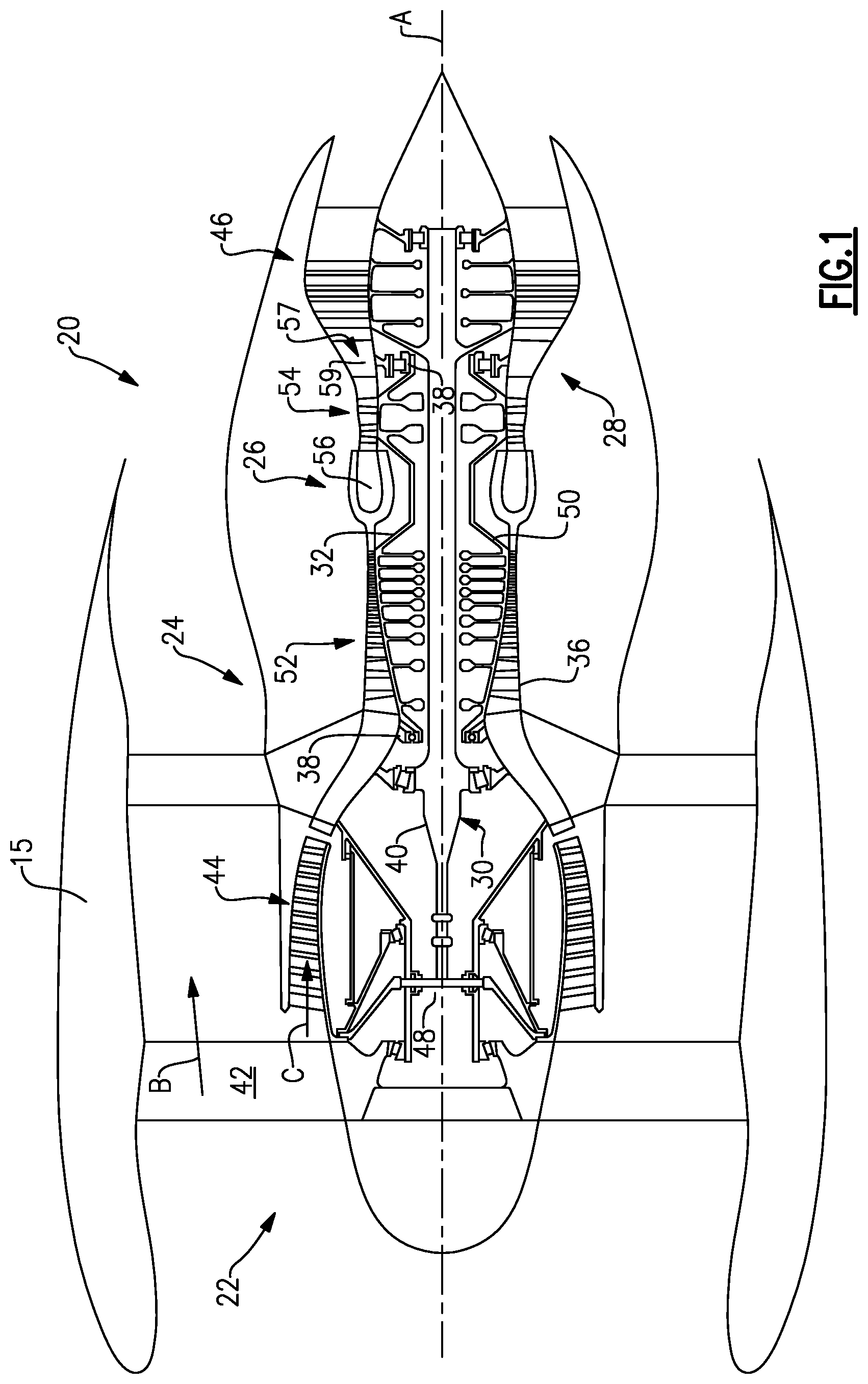
FIG. 1 is a schematic view of an example gas turbine engine.
FIG. 2 is a schematic view of an example geared architecture.
FIG. 3 is a schematic view of another example geared architecture.
DETAILED DESCRIPTION
FIG. 1 schematically illustrates a gas turbine engine 20. The gas turbine engine 20 is disclosed herein as a two-spool turbofan that generally incorporates a fan section 22, a compressor section 24, a combustor section 26 and a turbine section 28. Alternative engines might include an augmentor section (not shown) among other systems or features. The fan section 22 drives air along a bypass flow path B in a bypass duct defined within a nacelle 15, while the compressor section 24 drives air along a core flow path C for compression and communication into the combustor section 26 then expansion through the turbine section 28. Although depicted as a two-spool turbofan gas turbine engine in the disclosed non-limiting embodiment, it should be understood that the concepts described herein are not limited to use with two-spool turbofans as the teachings may be applied to other types of turbine engines including three-spool architectures.
The exemplary engine 20 generally includes a low speed spool 30 and a high speed spool 32 mounted for rotation about an engine central longitudinal axis A relative to an engine static structure 36 via several bearing systems 38. It should be understood that various bearing systems 38 at various locations may alternatively or additionally be provided, and the location of bearing systems 38 may be varied as appropriate to the application.
The low speed spool 30 generally includes an inner shaft 40 that interconnects a fan 42, a first (or low) pressure compressor 44 and a first (or low) pressure turbine 46. The inner shaft 40 is connected to the fan 42 through a speed change mechanism, which in exemplary gas turbine engine 20 is illustrated as a geared architecture 48 to drive the fan 42 at a lower speed than the low speed spool 30. The high speed spool 32 includes an outer shaft 50 that interconnects a second (or high) pressure compressor 52 and a second (or high) pressure turbine 54. A combustor 56 is arranged in exemplary gas turbine 20 between the high pressure compressor 52 and the high pressure turbine 54. A mid-turbine frame 57 of the engine static structure 36 is arranged generally between the high pressure turbine 54 and the low pressure turbine 46. The mid-turbine frame 57 further supports bearing systems 38 in the turbine section 28. The inner shaft 40 and the outer shaft 50 are concentric and rotate via bearing systems 38 about the engine central longitudinal axis A which is collinear with their longitudinal axes.
The core airflow is compressed by the low pressure compressor 44 with a compression ratio of at least 2:1 then the high pressure compressor 52, mixed and burned with fuel in the combustor 56, then expanded over the high pressure turbine 54 and low pressure turbine 46. The mid-turbine frame 57 includes airfoils 59 which are in the core airflow path C. The turbines 46, 54 rotationally drive the respective low speed spool 30 and high speed spool 32 in response to the expansion. It will be appreciated that each of the positions of the fan section 22, compressor section 24, combustor section 26, turbine section 28, and fan drive gear system 48 may be varied. For example, gear system 48 may be located aft of combustor section 26 or even aft of turbine section 28, and fan section 22 may be positioned forward or aft of the location of gear system 48.
The engine 20 in one example is a high-bypass geared aircraft engine. In a further example, the engine 20 bypass ratio is greater than about six (6), with an example embodiment being greater than about ten (10), the geared architecture 48 is an epicyclic gear train, such as a planetary gear system or other gear system, with a gear reduction ratio of greater than about 2.3 and the low pressure turbine 46 has a pressure ratio that is greater than about five. In one disclosed embodiment, the engine 20 bypass ratio is greater than about ten (10:1), the fan diameter is significantly larger than that of the low pressure compressor 44, and the low pressure turbine 46 has a pressure ratio that is greater than about five 5:1. Low pressure turbine 46 pressure ratio is pressure measured prior to inlet of low pressure turbine 46 as related to the pressure at the outlet of the low pressure turbine 46 prior to an exhaust nozzle. The geared architecture 48 may be an epicycle gear train, such as a planetary gear system or other gear system, with a gear reduction ratio of greater than about 2.3:1. It should be understood, however, that the above parameters are only exemplary of one embodiment of a geared architecture engine and that the present invention is applicable to other gas turbine engines including direct drive turbofans.
A significant amount of thrust is provided by the bypass flow B due to the high bypass ratio. The fan section 22 of the engine 20 is designed for a particular flight condition--typically cruise at about 0.8 Mach and about 35,000 feet. The flight condition of 0.8 Mach and 35,000 ft (10,668 meters), with the engine at its best fuel consumption--also known as "bucket cruise Thrust Specific Fuel Consumption ('TSFC)"--is the industry standard parameter of 1 bm of fuel being burned divided by 1 bf of thrust the engine produces at that minimum point. "Low fan pressure ratio" is the pressure ratio across the fan blade alone, without a Fan Exit Guide Vane ("FEGV") system. The low fan pressure ratio as disclosed herein according to one non-limiting embodiment is less than about 1.45. "Low corrected fan tip speed" is the actual fan tip speed in ft/sec divided by an industry standard temperature correction of [(Tram .degree. R)/(518.7.degree. R)].sup.0.5. The "Low corrected fan tip speed" as disclosed herein according to one non-limiting embodiment is less than about 1150 ft/second (350.5 meters/second).
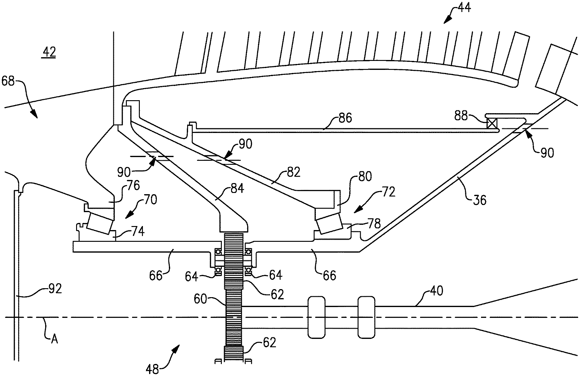
FIG. 2 illustrates the inner shaft 40 driving the geared architecture 48 to turn the fan 42 and the low pressure compressor 44 together at the same rotational speed. The inner shaft 40 is connected with a sun gear 60 in the geared architecture 48. The sun gear 60 is surrounded by star gears 62 mounted on star gear bearing assemblies 64 attached to a static carrier 66. The static carrier 66 allows the star gears 62 to rotate around an axis of each star gear 62 but not around and engine axis A. The static carrier 66 is fixed relative to the engine static structure 36 on the gas turbine engine 20.
The geared architecture 48 is located radially inward and axially aligned with the low pressure compressor 44 to shorten the overall length of the gas turbine engine 20.
A fan hub 68 is supported by a forward fan bearing 70 and an aft fan bearing 72. The forward fan bearing 70 includes an inner race 74 fixed to the static carrier 66 and an outer race 76 fixed to the fan hub 68. The forward fan bearing 70 supports radial and thrust loads from a forward end of the fan hub 68.
The aft fan bearing 72 includes an inner race 78 attached to the static carrier 66, which is connected with the engine static structure 36, and an outer race 80 is attached to a rotating aft support 82. The aft fan bearing 72 supports an aft end of the fan hub 68 and carries radial loads from the fan 42.
A rotatable ring gear 84 turns the fan hub 68 and the low pressure compressor 44 at the same rotational speed. A rotating compartment wall 86 extends from the rotating aft support 82 and is sealed against the engine static structure 36 with an oil seal 88.
Scavenged oil passes through holes 90 extending through the ring gear 84, the rotating aft support 82, and the engine static structure 36 to direct oil towards the forward and aft fan bearing 70 and 72 and the geared architecture 48. A rotating cover 92 aids in retaining and directing the oil towards the forward fan bearing 70, the aft fan bearing 72, and the geared architecture 48 and to prevent the need for carbon seals.
FIG. 3 illustrates another example geared architecture 148. The geared architecture 148 is similar to the geared architecture 48 shown in FIG. 2 except where shown in FIG. 3 or described below.
A static carrier 110 includes an oil baffle 100 extending from a forward end and a cylindrical support 102 for supporting the forward fan bearing 70. An oil feed tube 106 supplies oil to the static carrier 110 and the rest of geared architecture 148. A multitude of flexible shafts 112 extend from the static carrier 110 to support the star gears 62 and the respective star gear bearing assemblies 64. The flexibility of the shafts 112 support torsional loads from the star gears 62 and star gear bearing assemblies 64 and allow the star gears 62 to be isolated from the engine static structure 36 such that a static flexible mount is not necessary to mount the geared architecture 148.
The forward fan bearing 70 in this example includes a roller bearing with the inner race 74 mounted to the cylindrical support 102 and the outer race 76 rotatably attached to the fan hub 68 through a hub support 104. Although a roller bearing is illustrated in this example for the forward fan bearing 70, a ball bearing or a tapered bearing could also be utilized.
The aft fan bearing 72, such as a ball bearing, is mounted on an aft side of the geared architecture 148 opposite from the forward bearing 70. Although a ball bearing is illustrated in this example for the aft fan bearing 72, a roller bearing or a tapered bearing could also be utilized.
The forward fan bearing 70 and the aft fan bearing 72 straddle the geared architecture 148 to greatly reduce misalignment imparted on the geared architecture 148. This eliminates the need for a flexible coupling on the geared architecture 148 to combat misalignment forces acting on the gears.
An inner shaft bearing 114 attached to the engine static structure 36 supports a forward end of the inner shaft 40 and carries both radial and thrust loads. Since the fan 42 imparts a forward thrust load and low pressure turbine 46 imparts an aft thrust load on the inner shaft 40, the opposing loads are generally cancelled out by the aft fan bearing 72 and the inner shaft bearing 114 both being attached to the engine static structure 36.
The gas turbine engine 20 is designed by attaching the geared architecture 48 or 148 device to the fan hub 68 and the inner shaft 40. The forward fan bearing 70 is positioned forward of the geared architecture 48 or 148 with the first outer race 76 connected to the fan hub 68. The aft fan bearing 72 is positioned aft of the geared architecture 48 or 148. The inner race 74 and the inner race 78 are attached to the static carrier (66 or 110). The ring gear 85 from the geared architecture 48 or 148 is connected to the fan hub 68.
The preceding description is exemplary rather than limiting in nature. Variations and modifications to the disclosed examples may become apparent to those skilled in the art that do not necessarily depart from the essence of this disclosure. The scope of legal protection given to this disclosure can only be determined by studying the following claims.
* * * * *
References
-
mmsonline.com/articles/composite-fan-blade-containment-casepp
-
pyrografproducts.com/Merchant5/merchant.mvc?Screen=cp_nanofiber
-
scribd.com/document/153900429/GasTurb-12
-
gasturb.de/about-gasturb.html
-
-
datathief.org/DatathiefManual.pdfpp
-
cfmaeroengines.com
-
en.wikipedia.org/wiki/Torsion_spring
-
en.wikipedia.orgiwiki/Stiffness
-
researchgate.net/post/What_is_the_mesh_stiffness_ofgears
-
ntrs.nasa.gov/archive/nasa/casi.ntrs.nasa.gov/19800075257.pdf
-
cgabusinessdesk.com/document/aviation_tech_review.pdf
-
catalog.wshampshire.com/Asset/psg_teflon_ptfe.pdf
-
bloomberg.com/news/articles/2016-06-30/ge-wins-shot-to-invalidate-pratt-airplane-engine-patent-in-u-s
-
geaviation.com/sites/default/files/datasheet-CF6-80C2.pdf
-
geaviation.com/commercial/engines/ge90-engine
-
-
D00000
D00001
D00002
D00003
XML
uspto.report is an independent third-party trademark research tool that is not affiliated, endorsed, or sponsored by the United States Patent and Trademark Office (USPTO) or any other governmental organization. The information provided by uspto.report is based on publicly available data at the time of writing and is intended for informational purposes only.
While we strive to provide accurate and up-to-date information, we do not guarantee the accuracy, completeness, reliability, or suitability of the information displayed on this site. The use of this site is at your own risk. Any reliance you place on such information is therefore strictly at your own risk.
All official trademark data, including owner information, should be verified by visiting the official USPTO website at www.uspto.gov. This site is not intended to replace professional legal advice and should not be used as a substitute for consulting with a legal professional who is knowledgeable about trademark law.