Device for osteosyntheses or arthrodesis of two-bone parts, in particular of the hand and / or foot
Augoyard , et al. May 18, 2
U.S. patent number 11,006,984 [Application Number 16/020,005] was granted by the patent office on 2021-05-18 for device for osteosyntheses or arthrodesis of two-bone parts, in particular of the hand and / or foot. This patent grant is currently assigned to Stryker European Operations Holdings LLC. The grantee listed for this patent is Stryker European Operations Holdings LLC. Invention is credited to Marc Augoyard, Tristan Meusnier, Jacques Peyrot, Bernard Prandi.

| United States Patent | 11,006,984 |
| Augoyard , et al. | May 18, 2021 |
Device for osteosyntheses or arthrodesis of two-bone parts, in particular of the hand and / or foot
Abstract
In one embodiment, the present disclosure is a fixation device including a median zone, a first fixation zone including a base region extending from the median zone and an end region distant from the median zone, and including an expandable region in between the base region and the end region, the expandable region adapted to move between a closed position and an expanded position, wherein the first fixation zone is adapted to be positioned within a bone hole and, with the expandable region in the expanded position, the expandable region is positioned against bone surrounding the bone hole, and a second fixation zone including a base region extending from the median zone at a position different from the base region of the first fixation zone and an end region distant from the median zone.
| Inventors: | Augoyard; Marc (Tassin la Demi Lune, FR), Peyrot; Jacques (Tassin la Demi Lune, FR), Meusnier; Tristan (Saint-Etienne, FR), Prandi; Bernard (Rennes, FR) | ||||||||||
|---|---|---|---|---|---|---|---|---|---|---|---|
| Applicant: |
|
||||||||||
| Assignee: | Stryker European Operations
Holdings LLC (Kalamazoo, MI) |
||||||||||
| Family ID: | 1000005557645 | ||||||||||
| Appl. No.: | 16/020,005 | ||||||||||
| Filed: | June 27, 2018 |
Prior Publication Data
| Document Identifier | Publication Date | |
|---|---|---|
| US 20180303525 A1 | Oct 25, 2018 | |
Related U.S. Patent Documents
| Application Number | Filing Date | Patent Number | Issue Date | ||
|---|---|---|---|---|---|
| 15292955 | Oct 13, 2016 | 10022167 | |||
| 13896894 | Nov 15, 2016 | 9492215 | |||
| 11911405 | Jul 2, 2013 | 8475456 | |||
| PCT/FR2006/050345 | Apr 12, 2006 | ||||
Foreign Application Priority Data
| Apr 14, 2005 [FR] | 0550957 | |||
| Current U.S. Class: | 1/1 |
| Current CPC Class: | A61B 17/7225 (20130101); A61B 17/7291 (20130101); A61B 17/72 (20130101); A61B 17/7258 (20130101); A61B 17/7266 (20130101); A61B 17/844 (20130101); A61B 17/68 (20130101); A61B 17/7208 (20130101); A61B 2017/00867 (20130101); A61F 2002/30622 (20130101); A61F 2002/4243 (20130101); A61F 2210/0019 (20130101); A61B 2017/681 (20130101); A61F 2002/30092 (20130101) |
| Current International Class: | A61B 17/72 (20060101); A61B 17/00 (20060101); A61F 2/30 (20060101); A61B 17/68 (20060101); A61B 17/84 (20060101); A61F 2/42 (20060101) |
References Cited [Referenced By]
U.S. Patent Documents
| 1095054 | April 1914 | Wiesenfeld |
| 1517334 | December 1924 | Young |
| 1893864 | January 1933 | Kocher |
| 2580821 | January 1952 | Toufick |
| 2984248 | May 1961 | Sidelman |
| 3462765 | August 1969 | Swanson |
| 3466669 | September 1969 | Flatt |
| 3593342 | July 1971 | Niebauer et al. |
| 3681786 | August 1972 | Lynch |
| 3739403 | June 1973 | Nicolle |
| 3805302 | April 1974 | Mathys |
| 3824631 | July 1974 | Burstein et al. |
| 3875594 | April 1975 | Swanson |
| D243716 | March 1977 | Treace et al. |
| 4091806 | May 1978 | Aginsky et al. |
| 4158893 | June 1979 | Swanson |
| 4204284 | May 1980 | Koeneman |
| 4276660 | July 1981 | Laure |
| 4364382 | December 1982 | Mennen |
| 4367562 | January 1983 | Gauthier et al. |
| 4485816 | December 1984 | Krumme |
| D277509 | February 1985 | Lawrence et al. |
| D277784 | February 1985 | Sgarlato et al. |
| 4522200 | June 1985 | Stednitz |
| D284099 | June 1986 | Laporta et al. |
| 4634382 | January 1987 | Kusano et al. |
| D291731 | September 1987 | Aikins |
| 4759768 | July 1988 | Hermann et al. |
| 4871367 | October 1989 | Christensen et al. |
| 4905679 | March 1990 | Morgan |
| 4955916 | September 1990 | Carignan et al. |
| 4969909 | November 1990 | Barouk |
| 5011497 | April 1991 | Persson et al. |
| 5047059 | September 1991 | Saffar |
| 5062851 | November 1991 | Branemark |
| 5074865 | December 1991 | Fahmy |
| 5092896 | March 1992 | Meuli et al. |
| 5108443 | April 1992 | Branemark |
| 5133761 | July 1992 | Krouskop |
| 5179915 | January 1993 | Cohen et al. |
| 5190546 | March 1993 | Jervis |
| 5207712 | May 1993 | Cohen |
| 5326364 | July 1994 | Clift, Jr. et al. |
| 5360450 | November 1994 | Giannini |
| 5405400 | April 1995 | Linscheid et al. |
| 5405401 | April 1995 | Lippincott, III et al. |
| 5425776 | June 1995 | Cohen |
| 5425777 | June 1995 | Sarkisian et al. |
| 5454814 | October 1995 | Comte |
| 5464427 | November 1995 | Curtis et al. |
| 5474557 | December 1995 | Mai |
| D366114 | January 1996 | Ohata |
| 5480447 | January 1996 | Skiba |
| 5484443 | January 1996 | Pascarella et al. |
| D369412 | April 1996 | Morgan |
| 5507822 | April 1996 | Bouchon et al. |
| 5522903 | June 1996 | Sokolow et al. |
| 5554157 | September 1996 | Errico et al. |
| 5578036 | November 1996 | Stone et al. |
| 5634925 | June 1997 | Urbanski |
| 5674297 | October 1997 | Lane et al. |
| 5690631 | November 1997 | Duncan et al. |
| 5702472 | December 1997 | Huebner |
| D388877 | January 1998 | Morgan |
| 5725585 | March 1998 | Zobel |
| 5779707 | July 1998 | Bertholet et al. |
| 5782927 | July 1998 | Klawitter et al. |
| 5824095 | October 1998 | Di Maio, Jr. et al. |
| 5876434 | March 1999 | Flomenblit et al. |
| 5882444 | March 1999 | Flomenblit et al. |
| 5919193 | July 1999 | Slavitt |
| 5951288 | September 1999 | Sawa |
| 5958159 | September 1999 | Prandi |
| 5984970 | November 1999 | Bramlet |
| 5984971 | November 1999 | Faccioli et al. |
| 6011497 | January 2000 | Tsang et al. |
| 6017366 | January 2000 | Berman |
| 6093188 | July 2000 | Murray |
| 6123709 | September 2000 | Jones |
| 6146387 | November 2000 | Trott et al. |
| 6162234 | December 2000 | Freedland et al. |
| 6193757 | February 2001 | Foley et al. |
| 6197037 | March 2001 | Hair |
| 6200330 | March 2001 | Benderev et al. |
| 6248109 | June 2001 | Stoffella |
| 6261289 | July 2001 | Levy |
| 6319284 | November 2001 | Rushdy et al. |
| 6325805 | December 2001 | Ogilvie et al. |
| 6342076 | January 2002 | Lundborg |
| 6348052 | February 2002 | Sammarco |
| 6352560 | March 2002 | Poeschmann et al. |
| 6383223 | May 2002 | Baehler et al. |
| 6386877 | May 2002 | Sutter |
| 6423097 | July 2002 | Rauscher |
| 6428634 | August 2002 | Besselink et al. |
| 6454808 | September 2002 | Masada |
| 6475242 | November 2002 | Bramlet |
| 6554833 | April 2003 | Levy et al. |
| 6689169 | February 2004 | Harris |
| 6692499 | February 2004 | Tormala et al. |
| 6699247 | March 2004 | Zucherman et al. |
| 6699292 | March 2004 | Ogilvie et al. |
| 6706045 | March 2004 | Lin et al. |
| 6736818 | May 2004 | Perren |
| 6773437 | August 2004 | Ogilvie et al. |
| 6811568 | November 2004 | Minamikawa |
| 6827741 | December 2004 | Reeder |
| 6869449 | March 2005 | Ball et al. |
| 6896177 | May 2005 | Carter |
| 6981974 | January 2006 | Berger |
| 7025789 | April 2006 | Chow et al. |
| 7037342 | May 2006 | Nilsson et al. |
| 7041106 | May 2006 | Carver et al. |
| 7052498 | May 2006 | Levy et al. |
| 7182787 | February 2007 | Hassler et al. |
| 7240677 | July 2007 | Fox |
| 7291175 | November 2007 | Gordon |
| 7588603 | September 2009 | Leonard |
| 7655042 | February 2010 | Foley et al. |
| 7780737 | August 2010 | Bonnard et al. |
| 7837738 | November 2010 | Reigstad et al. |
| 7842091 | November 2010 | Johnstone et al. |
| 7909880 | March 2011 | Grant |
| 7922765 | April 2011 | Reiley |
| 7955388 | June 2011 | Jensen et al. |
| 7976580 | July 2011 | Berger |
| 8048173 | November 2011 | Ochoa |
| 8100983 | January 2012 | Schulte |
| 8162942 | April 2012 | Coati et al. |
| 8202305 | June 2012 | Reiley |
| 8262712 | September 2012 | Coilard-Lavirotte et al. |
| 8308779 | November 2012 | Reiley |
| 8394097 | March 2013 | Peyrot et al. |
| 8414583 | April 2013 | Prandi et al. |
| 8475456 | July 2013 | Augoyard et al. |
| 8529611 | September 2013 | Champagne et al. |
| 8597337 | December 2013 | Champagne |
| 8608785 | December 2013 | Reed et al. |
| 8685024 | April 2014 | Roman |
| 8715325 | May 2014 | Weiner et al. |
| 8840623 | September 2014 | Reiley |
| 8864804 | October 2014 | Champagne et al. |
| 9011504 | April 2015 | Reed |
| 9125698 | September 2015 | Miller |
| 9283007 | March 2016 | Augoyard et al. |
| 2001/0025199 | September 2001 | Rauscher |
| 2001/0049529 | December 2001 | Cachia |
| 2002/0019636 | February 2002 | Ogilvie et al. |
| 2002/0055785 | May 2002 | Harris |
| 2002/0065561 | May 2002 | Ogilvie et al. |
| 2002/0068939 | June 2002 | Levy et al. |
| 2002/0082705 | June 2002 | Bouman et al. |
| 2002/0099395 | July 2002 | Acampora et al. |
| 2002/0133156 | September 2002 | Cole |
| 2002/0169066 | November 2002 | Cassidy et al. |
| 2002/0189622 | December 2002 | Cauthen et al. |
| 2003/0040805 | February 2003 | Minamikawa |
| 2003/0069645 | April 2003 | Ball et al. |
| 2003/0120277 | June 2003 | Berger |
| 2003/0130660 | July 2003 | Levy et al. |
| 2004/0002759 | January 2004 | Ferree |
| 2004/0093081 | May 2004 | Nilsson et al. |
| 2004/0102853 | May 2004 | Boumann et al. |
| 2004/0138756 | July 2004 | Reeder |
| 2004/0220678 | November 2004 | Chow et al. |
| 2004/0230193 | November 2004 | Cheung |
| 2005/0065589 | March 2005 | Schneider |
| 2005/0119757 | June 2005 | Hassler et al. |
| 2005/0124990 | June 2005 | Teague et al. |
| 2005/0251265 | November 2005 | Calandruccio et al. |
| 2005/0261768 | November 2005 | Trieu |
| 2005/0283159 | December 2005 | Amara |
| 2006/0015181 | January 2006 | Elberg |
| 2006/0052725 | March 2006 | Santilli |
| 2006/0052878 | March 2006 | Schmieding |
| 2006/0074492 | April 2006 | Frey |
| 2006/0084998 | April 2006 | Levy et al. |
| 2006/0085075 | April 2006 | McLeer |
| 2006/0247787 | November 2006 | Rydell et al. |
| 2007/0038303 | February 2007 | Myerson et al. |
| 2007/0123993 | May 2007 | Hassler et al. |
| 2007/0142920 | June 2007 | Niemi |
| 2007/0156241 | July 2007 | Reiley et al. |
| 2007/0185584 | August 2007 | Kaufmann et al. |
| 2007/0198088 | August 2007 | Biedermann et al. |
| 2007/0213831 | September 2007 | de Cubber |
| 2007/0239158 | October 2007 | Trieu et al. |
| 2008/0039949 | February 2008 | Meesenburg et al. |
| 2008/0132894 | June 2008 | Coilard-Lavirotte et al. |
| 2008/0154385 | June 2008 | Trail et al. |
| 2008/0177262 | July 2008 | Augoyard et al. |
| 2008/0195219 | August 2008 | Wiley et al. |
| 2008/0221697 | September 2008 | Graser |
| 2008/0221698 | September 2008 | Berger |
| 2008/0234763 | September 2008 | Patterson et al. |
| 2008/0269908 | October 2008 | Warburton |
| 2009/0005821 | January 2009 | Chirico et al. |
| 2009/0012564 | January 2009 | Chirico et al. |
| 2009/0138096 | May 2009 | Myerson et al. |
| 2009/0254189 | October 2009 | Scheker |
| 2009/0254190 | October 2009 | Gannoe et al. |
| 2010/0010637 | January 2010 | Pequignot |
| 2010/0016905 | January 2010 | Greenhalgh et al. |
| 2010/0016982 | January 2010 | Solomons |
| 2010/0057214 | March 2010 | Graham et al. |
| 2010/0121390 | May 2010 | Kleinman |
| 2010/0131014 | May 2010 | Peyrot |
| 2010/0131072 | May 2010 | Schulte |
| 2010/0161068 | June 2010 | Lindner et al. |
| 2010/0185295 | July 2010 | Emmanuel |
| 2010/0228301 | September 2010 | Greenhalgh et al. |
| 2010/0249942 | September 2010 | Goswami et al. |
| 2010/0256770 | October 2010 | Hakansson et al. |
| 2010/0262254 | October 2010 | Lawrence et al. |
| 2011/0004317 | January 2011 | Hacking et al. |
| 2011/0093084 | April 2011 | Morton |
| 2011/0093085 | April 2011 | Morton |
| 2011/0144644 | June 2011 | Prandi et al. |
| 2011/0301652 | December 2011 | Reed et al. |
| 2011/0301653 | December 2011 | Reed et al. |
| 2012/0029579 | February 2012 | Bottlang et al. |
| 2012/0065692 | March 2012 | Champagne et al. |
| 2012/0083791 | April 2012 | Cheney et al. |
| 2012/0089197 | April 2012 | Anderson |
| 2013/0053975 | February 2013 | Reed et al. |
| 2013/0060295 | March 2013 | Reed et al. |
| 2013/0066435 | March 2013 | Averous et al. |
| 2013/0131822 | May 2013 | Lewis et al. |
| 2013/0150965 | June 2013 | Taylor et al. |
| 2013/0190761 | July 2013 | Prandi et al. |
| 2014/0058462 | February 2014 | Reed et al. |
| 2014/0142715 | May 2014 | McCormick |
| 2014/0180428 | June 2014 | McCormick |
| 2014/0188239 | July 2014 | Cummings |
| 2015/0073413 | March 2015 | Palmer et al. |
| 2015/0223849 | August 2015 | McCormick et al. |
| 2017/0065310 | March 2017 | Girod et al. |
| 2551021 | Mar 2005 | CA | |||
| 2243699 | Jan 2006 | CA | |||
| 2836654 | Jun 2014 | CA | |||
| 2837497 | Jun 2014 | CA | |||
| 0042808 | Dec 1981 | EP | |||
| 0420794 | Apr 1991 | EP | |||
| 0454645 | Oct 1991 | EP | |||
| 1300122 | Apr 2003 | EP | |||
| 1356794 | Nov 2003 | EP | |||
| 1582159 | Oct 2005 | EP | |||
| 1923012 | May 2008 | EP | |||
| 2663838 | Jan 1992 | FR | |||
| 2725126 | Apr 1996 | FR | |||
| 2783702 | Mar 2000 | FR | |||
| 2787313 | Jun 2000 | FR | |||
| 2794019 | Dec 2000 | FR | |||
| 2801189 | May 2001 | FR | |||
| 2846545 | May 2004 | FR | |||
| 2884406 | Oct 2006 | FR | |||
| 2119655 | Nov 1983 | GB | |||
| 2430625 | Apr 2007 | GB | |||
| S60145133 | Jul 1985 | JP | |||
| 03001854 | Aug 1991 | JP | |||
| H7303662 | Nov 1995 | JP | |||
| 2004535249 | Nov 2004 | JP | |||
| 3648687 | May 2005 | JP | |||
| 2007530194 | Nov 2007 | JP | |||
| 2008188411 | Aug 2008 | JP | |||
| 2008537696 | Sep 2008 | JP | |||
| 4695511 | Jun 2011 | JP | |||
| 5631597 | Nov 2014 | JP | |||
| 20070004513 | Jan 2007 | KR | |||
| 20070022256 | Feb 2007 | KR | |||
| 101004561 | Jan 2011 | KR | |||
| 101235983 | Feb 2013 | KR | |||
| 9116014 | Oct 1991 | WO | |||
| 9625129 | Aug 1996 | WO | |||
| 9641596 | Dec 1996 | WO | |||
| 9726846 | Jul 1997 | WO | |||
| 9733537 | Sep 1997 | WO | |||
| 0117445 | Mar 2001 | WO | |||
| 03084416 | Oct 2003 | WO | |||
| 2005020830 | Mar 2005 | WO | |||
| 2005063149 | Jul 2005 | WO | |||
| 2005104961 | Nov 2005 | WO | |||
| 2006109004 | Oct 2006 | WO | |||
| 2008057404 | May 2008 | WO | |||
| 2008112308 | Sep 2008 | WO | |||
| 2009103085 | Aug 2009 | WO | |||
| 2011130229 | Oct 2011 | WO | |||
Other References
|
International Search Report for PCT/FR2008/050453 dated Nov. 4, 2008, 4 pages. cited by applicant . International Search Report, PCT/FR2006/050345, dated Aug. 30, 2006, 3 pages. cited by applicant. |
Primary Examiner: Sevilla; Christian A
Attorney, Agent or Firm: Lerner, David, Littenberg, Krumholz & Mentlik, LLP
Parent Case Text
CROSS-REFERENCE TO RELATED APPLICATIONS
This application is a continuation of U.S. application Ser. No. 15/292,955, filed Oct. 13, 2016, which is a continuation of U.S. application Ser. No. 13/896,894, filed May 17, 2013, which is a continuation of U.S. application Ser. No. 11/911,405, filed Mar. 17, 2008, which is a US national phase of PCT Publication PCT/FR2006/050345, filed 12 Apr. 2006, published 19 Oct. 2006 as WO2006/109004, and claiming the priority of French Application No. 0550957, filed Apr. 14, 2005, the entire disclosures of each of which are herewith incorporated by reference herein.
Claims
The invention claimed is:
1. An intramedullary fixation device, comprising: a monolithic body including a non-expandable median zone having a first width, a first fixation zone and a second fixation zone; the first fixation zone including a base region at a first end of the median zone, the base region having a second width, an end region distant from the median zone, and an expandable region in between the base region and the end region, the expandable region adapted to move between a closed position and an expanded position, wherein the first fixation zone is adapted to be positioned within a bone hole and, with the expandable region in the expanded position, the expandable region is positioned against bone surrounding the bone hole, the first width being greater than the second width; and the second fixation zone including a base region at a second end of the median zone at a position different from the base region of the first fixation zone and an end region distant from the median zone, wherein the second fixation zone is adapted to be positioned within a second bone hole.
2. The device of claim 1, wherein the expandable region, when in the expanded position, includes a first contact region which is positioned against bone surrounding the bone hole.
3. The device of claim 1, wherein the first fixation zone includes first and second tabs which at the base region each extend from the median zone to the end region distant from the median zone.
4. The device of claim 3, wherein each of the first and second tabs of the first fixation zone includes a respective expandable region which, in the closed position are adjacent one another and in the expanded position are distant from one another and are each positioned against bone surrounding the bone hole.
5. The device of claim 1, wherein at least the median zone and one of the first fixation zone or second fixation zone has a flat cross-section.
6. The device of claim 1, wherein the second fixation zone includes first and second tabs which at the base region each extend from the median zone to the end region distant from the median zone.
7. The device of claim 6, wherein each of the first and second tabs of the second fixation zone includes a second contact region for engagement with bone surrounding the second bone hole.
8. An intramedullary fixation device, comprising: a monolithic body having a non-expandable median zone having a first width and a first fixation zone, the first fixation zone including a base region at a first end of the median zone and having a second width, an end region distant from the median zone, and an expandable region in between the base region and the end region, the expandable region having a first contact region and adapted to move between a closed position and an expanded position, wherein the first fixation zone is adapted to be positioned within a bone hole and, with the expandable region in the expanded position, the first contact region is positioned against bone surrounding the bone hole, the first width being greater than the second width.
9. The device of claim 8, further comprising a second fixation zone including a base region at a second end of the median zone at a position different from the base region of the first fixation zone and an end region distant from the median zone.
10. The device of claim 9, wherein the second fixation zone includes first and second tabs which at the base region each extend from the median zone to the end region distant from the median zone.
11. The device of claim 10, wherein the second fixation zone is adapted to be positioned within a second bone hole, and each of the first and second tabs of the second fixation zone includes a second contact region for engagement with bone surrounding the second bone hole.
12. The device of claim 8, wherein the first fixation zone includes first and second tabs which at the base region each extend from the median zone to the end region distant from the median zone.
13. The device of claim 12, wherein each of the first and second tabs of the first fixation zone includes a respective expandable region which, in the closed position are adjacent one another and in the expanded position are distant from one another and are each positioned against bone surrounding the bone hole.
14. The device of claim 8, wherein at least the median zone and one of the first fixation zone or second fixation zone has a flat cross-section.
15. An intramedullary fixation device, comprising: a monolithic body having a non-expandable median zone having a first width and a first fixation zone, the first fixation zone including first and second tabs, each tab extending from a base region having a second width, the base region adjoining an end of the median zone, each tab having an end region distant from the median zone, and each tab having an expandable region in between the base region and the end region, the expandable region of each tab adapted to move between a closed position and an expanded position, wherein the first fixation zone is adapted to be positioned within a bone hole and, with the expandable region in the expanded position, the expandable region is positioned against bone surrounding the bone hole, the first width being greater than the second width.
16. The device of claim 15, further comprising a second fixation zone including a base region extending from the median zone at a position different from the base region of the first fixation zone and an end region distant from the median zone.
17. The device of claim 16, wherein the expandable region of each tab, when in the expanded position, includes a first contact region which is positioned against bone surrounding the bone hole.
18. The device of claim 17, wherein the first contact regions of the first and second tabs are adjacent one another when in the closed positioned and are distant from one another when in the expanded position.
19. The device of claim 15, wherein the median zone and the first fixation zone have a flat cross-section.
Description
FIELD OF THE INVENTION
The invention relates to the technical field of orthopaedic implants, particularly for arthrodesis and osteosyntheses.
It may be recalled that the object of an arthrodesis is to obtain very good stability both primary and secondary, and to place, or to maintain, in compression, two bone parts or bone fragments that should be consolidated. Stability is a critical factor for obtaining consolidation, while minimizing the attendant problems such as pain, swelling, etc. The compressive action serves to consolidate the osteotomy more rapidly in the position selected by the surgeon during the operation.
Various technical solutions have been proposed for carrying out an arthrodesis, particularly in the foot, the hand, the wrist, etc. Mention can be made, for example, of basic staples without shape memory which do not produce a compression, as opposed to memory staples which serve to place the two bone parts to be consolidated in compression, which corresponds to the objective.
However, to obtain satisfactory stability, it is necessary to place two, or even three staples, in different planes. This increases the dimensions considerably, thereby limiting applications (metacarpo-phalangeal joint, for example).
Extramedullary plates and screws have also been proposed, requiring an alternatively large dimension. In this respect, their miniaturization is difficult to conceive, because this could raise problems of strength and stiffness. Some types of screws can be used in intramedullary osteosynthesis, but they raise positioning difficulties (passage through the pad in particular).
Use can also be made of pins which have a smaller size. However, the stability obtained is unsatisfactory and it is necessary to withdraw them.
Intramedullary nails are also known, but they require supplementary stapling in order to prevent the bone parts to be joined from rotating relative to each other.
OBJECT OF THE INVENTION
It is the object of the invention to remedy these drawbacks simply, safely, effectively and efficiently.
The problem that the invention proposes to solve is to permit the fixation of two bone parts to one another, rigidly with dynamic and retentive compression, in order to obtain a reliable and rapid osteosynthesis.
SUMMARY OF THE INVENTION
To solve such a problem, an intramedullary arthrodesis element has been designed and developed which consists of a body with an elongated shape having, in succession, from one of its ends, a fixation zone cooperating with one of the bone parts to be immobilized, a median zone suitable for withstanding shear and bending stresses, and a fixation zone in the other bone part to be immobilized, each of the fixation zones being profiled and made from a material suitable for enabling introduction into the bone parts without a finger- or toe-tip approach, followed by a fixation in the bone parts, while avoiding any rotational movement, withstanding the tensile stresses, and maintaining a compressive force.
The invention has a particularly advantageous application, which can however not be considered as limiting, for the preparation of arthrodesis in the proximal and median phalanges, for proximal interphalangeal joints and distal interphalangeal joints, in the hand or foot.
To solve the problem of taking account of the anatomy, and particularly of the internal shrinkage of the bone, the median zone is linked to at least one of the fixation zones by a connecting zone.
To solve the problem of permitting implantation of the element followed by compression of the bone fragments, the fixation zones are made from a shape-memory material to be deformed by thermal and/or mechanical action.
To produce the fixation zones, which may be identical or not, various technical solutions are feasible, according in particular to the type of arthrodesis performed and the joints to be treated.
For example:
one of the fixation zones has two tabs or wings separable under the action of the shape memory;
one of the fixation zones has a tab or rod which can be curved under the action of the shape memory;
one of the fixation zones has, in its thickness, a slot for permitting deformation by elasticity, or memory, under the action of the shape memory.
In one embodiment, the overall body has a flat cross-section.
BRIEF DESCRIPTION OF THE DRAWING
The invention is described below in greater detail in conjunction with the figures of the drawings appended hereto in which:
FIG. 1 is a schematic plan view showing the placement of the intramedullary arthrodesis element of the invention between a proximal phalange and a median phalange to consolidate the proximal interphalangeal joint;
FIG. 2 is a plan view of an embodiment of the arthrodesis element at the time of its introduction;
FIG. 3 is a view corresponding to FIG. 2 showing the arthrodesis element after its implant to produce the compression;
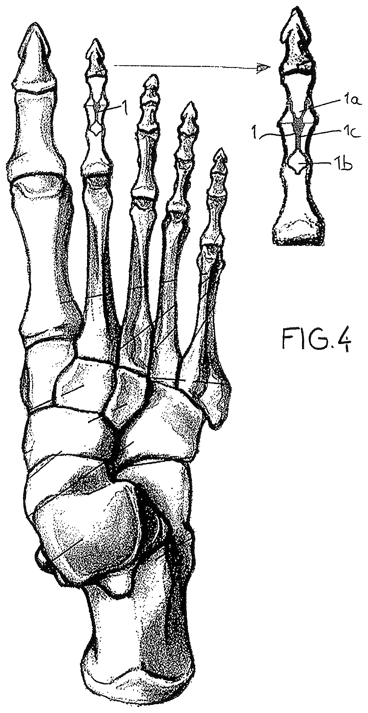
FIG. 4 shows the placement of the element of the invention in a toe.
SPECIFIC DESCRIPTION
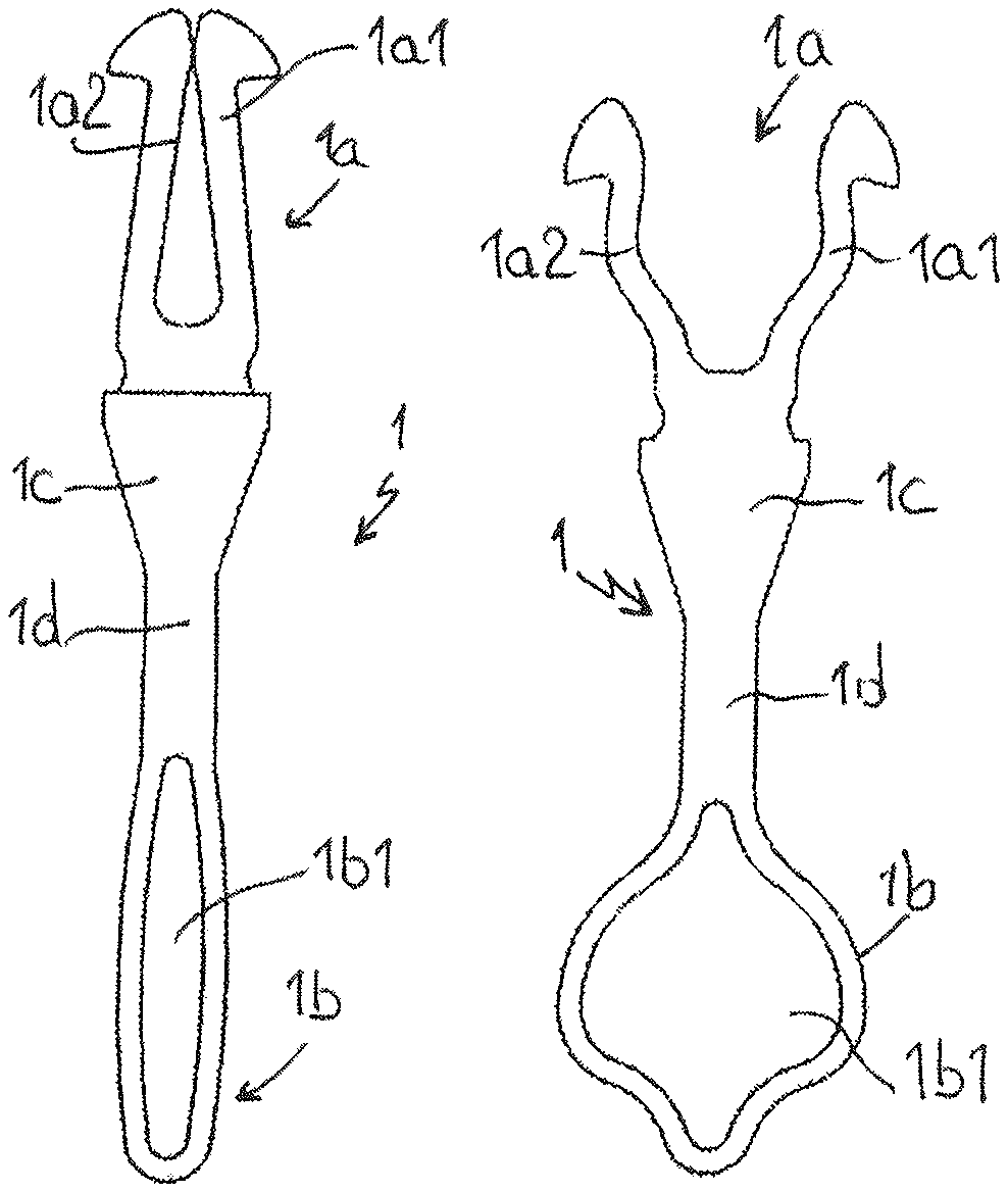
The arthrodesis element of the invention consists of an elongated body 1. Each of the ends of the body 1 is conformed to produce a fixation zone 1a linked to a fixation zone 1b.
Between the two fixation zones 1a and 1b, at least one median zone 1c is formed capable of withstanding shear and bending stresses. In general, the shear and bending stresses are applied to the bone site to be consolidated. The shape of this median zone 1c is adapted to the internal shape of the bone. Its length is determined in order to allow a slight offset in the centering.
For information, and in a non-limiting manner, this median zone may have a rectangular cross-section measuring about 2 to 3 mm*1 to 1.5 mm and a length of about 3 to 5 mm for the foot and the hand.
The fixation zones 1a and 1b are conformed to prevent any rotational movement, resist tension, and maintain manual compression applied at the time of the implant by the surgeon in order to reduce the site. To obtain this result, the fixation zones 1a and 1b are made from a shape-memory material to be deformed by thermal action (tepid memory) or mechanical action (superelasticity) (see U.S. Pat. No. 5,958,159). The goal, in the fixation zones, considering their profile on the one hand and the type of material on the other, is to permit an introduction into the bone parts, particularly dorsally without a finger- or toe-tip approach, on the one hand, and to produce a fixation in the bone portion in order to obtain or to maintain the desired compressive force, on the other. The fixation zones 1a and 1b are identical or not, according to the type of bone and its morphology.
Depending on the type of arthrodesis performed, that is, the type of interphalangeal joint to be consolidated for example, the fixation zones 1a and 1b may have different embodiments.
For example, one of the fixation zones 1a has two tabs or wings that are separable under a thermal action for example. Otherwise, these fixation zones 1a may have a single tab or rod which can be curved under the action of a memory of the component material. Otherwise, the fixation zone 1b has, in its thickness, a slot to permit deformation by elasticity, under thermal action for example, and to maintain the position by pressing on the length of the bone.
According to another feature of the invention, to take account of the anatomy of the various phalanges for example, that is the internal shrinkage of the bone (hourglass shape), the median zone 1c is linked to at least one of the fixation zones 1b by a thinner connecting zone 1d.
Reference can be made to the figures of the drawings which show an embodiment of an intramedullar arthrodesis element.
In this embodiment, the body 1 has, at one of its ends, a fixation zone 1a in the form of two tabs or wings 1a1 1a2. This fixation zone 1a is prolonged by a median zone 1c of generally substantially triangular shape in a plan view. The median zone 1c is connected to the other end fixation zone 1b by a connecting zone 1d having a generally rectangular shape in a plan view. The fixation zone 1b has, in its thickness, a slot of generally oblong shape 1b1.
Reference can be made to FIG. 2 which shows the element at the time of its introduction, that is before separation of the tabs 1a1 and 1a2, and the opening of the slot 1b1. For example, this configuration is obtained when the overall element is subject to a temperature much lower than that of the human body for example. Conversely, after implantation (FIG. 3), under the effect of body heat, the tabs 1a1 and 1a2 separate, in the same way as the slot 1b1, concomitantly causing a deformation of the fixation zone 1b.
It should be noted that the profile of the median zone 1c prevents penetration when the site is reclosed.
In an alternative embodiment, the connecting zone 1d can be split to benefit from a swelling effect by shape memory and strengthening of the anchoring in the diaphyseal zone.
It should be recalled that the inventive element is ideal for the treatment of the hammer- or claw-toe syndrome, by performing an arthrodesis in the phalanges P1 and P2 on the radii 2 to 5, while observing that such applications must not be considered as limiting, by means of essentially dimensional adjustments (finger reimplants, arthrodesis of the distal interphalangeal joint and of the proximal interphalangeal joint of the hand, and the arthrodesis of the big toe).
Obviously, the entire arthrodesis element of the invention may have constructive features suitable for improving the fixation and compression in particular.
For example:
notches on the tabs on one of the sides for better fixation in the ethmoid bone;
wavy tabs implanted (straight before implant)
to permit shortening and hence an additional compression of the arthrodesis site compared with a simple fixation;
a tapered central zone to avoid undesirable
penetration of the implant at the time when the site is to be closed.
For information, the memory used is preferably a tepid memory, so that heating is unnecessary because of the lack of access. The opening begins at above 15 to 20.degree. C. and stops at about 30 to 35.degree. C.
The operating technique remains conventional.
* * * * *
D00000
D00001
D00002
XML
uspto.report is an independent third-party trademark research tool that is not affiliated, endorsed, or sponsored by the United States Patent and Trademark Office (USPTO) or any other governmental organization. The information provided by uspto.report is based on publicly available data at the time of writing and is intended for informational purposes only.
While we strive to provide accurate and up-to-date information, we do not guarantee the accuracy, completeness, reliability, or suitability of the information displayed on this site. The use of this site is at your own risk. Any reliance you place on such information is therefore strictly at your own risk.
All official trademark data, including owner information, should be verified by visiting the official USPTO website at www.uspto.gov. This site is not intended to replace professional legal advice and should not be used as a substitute for consulting with a legal professional who is knowledgeable about trademark law.