Connection systems and methods thereof for establishing an electrical connection through a drape
Thompson , et al. April 19, 2
U.S. patent number 11,304,772 [Application Number 16/932,425] was granted by the patent office on 2022-04-19 for connection systems and methods thereof for establishing an electrical connection through a drape. This patent grant is currently assigned to Bard Access Systems, Inc.. The grantee listed for this patent is Bard Access Systems, Inc.. Invention is credited to Kent F. Beck, Chase Thompson, Jerry Zhao.

| United States Patent | 11,304,772 |
| Thompson , et al. | April 19, 2022 |
Connection systems and methods thereof for establishing an electrical connection through a drape
Abstract
Connection systems are disclosed for establishing one or more electrical connections through a drape. An example connection system includes a first connector and a second connector configured to connect to each other. The first connector includes a first-connector housing, an electrical lead extending from the first-connector housing, and at least a first piercing element within the first-connector housing configured to pierce the drape. The first piercing element is orthogonally connected to the electrical lead. The second connector includes a second-connector housing and at least a first receptacle within the second-connector housing. The first receptacle is configured to form at least a first electrical connection of the one or more electrical connections with the first piercing element when the first connector is disposed over the second connector with the drape therebetween. Methods are also disclosed herein for establishing one or more electrical connections through a drape with the connection systems.
| Inventors: | Thompson; Chase (Bountiful, UT), Zhao; Jerry (Salt Lake City, UT), Beck; Kent F. (Layton, UT) | ||||||||||
|---|---|---|---|---|---|---|---|---|---|---|---|
| Applicant: |
|
||||||||||
| Assignee: | Bard Access Systems, Inc. (Salt
Lake City, UT) |
||||||||||
| Family ID: | 1000006250015 | ||||||||||
| Appl. No.: | 16/932,425 | ||||||||||
| Filed: | July 17, 2020 |
Prior Publication Data
| Document Identifier | Publication Date | |
|---|---|---|
| US 20200345441 A1 | Nov 5, 2020 | |
Related U.S. Patent Documents
| Application Number | Filing Date | Patent Number | Issue Date | ||
|---|---|---|---|---|---|
| 16402074 | May 2, 2019 | 10772696 | |||
| 62673726 | May 18, 2018 | ||||
| Current U.S. Class: | 1/1 |
| Current CPC Class: | A61B 46/23 (20160201); A61M 39/18 (20130101); A61B 2046/234 (20160201) |
| Current International Class: | H01R 13/04 (20060101); A61M 39/18 (20060101); A61B 46/23 (20160101) |
| Field of Search: | ;439/444,660,909 |
References Cited [Referenced By]
U.S. Patent Documents
| 2831174 | April 1958 | Hilmo |
| 2959766 | November 1960 | Edwin |
| 3329928 | July 1967 | Broske |
| 3532095 | October 1970 | Miller et al. |
| 3597582 | August 1971 | Goode et al. |
| 3605743 | September 1971 | Arce |
| 3665372 | May 1972 | Goode et al. |
| 3673548 | June 1972 | Mattingly, Jr. et al. |
| 3746814 | July 1973 | Lackey et al. |
| 3824556 | July 1974 | Berkovits et al. |
| 3842394 | October 1974 | Bolduc |
| 4200348 | April 1980 | Stupay |
| 4220387 | September 1980 | Biche et al. |
| 4254764 | March 1981 | Neward |
| 4303293 | December 1981 | Grunwald |
| 4369794 | January 1983 | Furler |
| 4490003 | December 1984 | Robinson |
| 4614395 | September 1986 | Peers-Trevarton |
| 4632121 | December 1986 | Johnson et al. |
| 4700997 | October 1987 | Strand |
| 4702256 | October 1987 | Robinson et al. |
| 4761143 | August 1988 | Owens et al. |
| 4858810 | August 1989 | Intlekofer et al. |
| 4860742 | August 1989 | Park et al. |
| 4973329 | November 1990 | Park et al. |
| 5159861 | November 1992 | Anderson |
| 5178159 | January 1993 | Christian |
| 5217435 | June 1993 | Kring |
| 5325746 | July 1994 | Anderson |
| 5325868 | July 1994 | Kimmelstiel |
| 5334045 | August 1994 | Cappa et al. |
| 5354326 | October 1994 | Comben et al. |
| 5407368 | April 1995 | Strand et al. |
| 5423877 | June 1995 | Mackey |
| 5437277 | August 1995 | Dumoulin et al. |
| 5454739 | October 1995 | Strand |
| 5482038 | January 1996 | Ruff |
| 5489225 | February 1996 | Julian |
| 5501675 | March 1996 | Erskine |
| 5538444 | July 1996 | Strand et al. |
| 5560358 | October 1996 | Arnold et al. |
| 5591119 | January 1997 | Adair |
| 5624281 | April 1997 | Christensson |
| 5685855 | November 1997 | Erskine |
| 5752915 | May 1998 | Neubauer et al. |
| 5766042 | June 1998 | Ries et al. |
| 5769786 | June 1998 | Wiegel |
| 5797880 | August 1998 | Erskine |
| 5840024 | November 1998 | Taniguchi et al. |
| 5968082 | October 1999 | Heil |
| 5984918 | November 1999 | Garito et al. |
| 6050976 | April 2000 | Thorne et al. |
| 6090052 | July 2000 | Akerfeldt et al. |
| 6102044 | August 2000 | Naidyhorski |
| 6132368 | October 2000 | Cooper |
| 6140722 | October 2000 | Ballard |
| 6162101 | December 2000 | Fischer et al. |
| 6324416 | November 2001 | Seibert |
| 6330480 | December 2001 | Van der Linden et al. |
| 6350160 | February 2002 | Feuersanger et al. |
| 6415168 | July 2002 | Putz |
| 6428336 | August 2002 | Akerfeldt |
| 6546270 | April 2003 | Goldin et al. |
| 6620136 | September 2003 | Pressly, Sr. et al. |
| 6663570 | December 2003 | Mott et al. |
| 6673078 | January 2004 | Muncie |
| 6714809 | March 2004 | Lee et al. |
| 6780065 | August 2004 | Schwarz |
| 6799991 | October 2004 | Williams et al. |
| 6913478 | July 2005 | Lamirey |
| 7130699 | October 2006 | Huff et al. |
| 7144378 | December 2006 | Arnott |
| 7255609 | August 2007 | Epstein |
| 7274956 | September 2007 | Mott et al. |
| 7402083 | July 2008 | Kast et al. |
| 7452360 | November 2008 | Trudeau et al. |
| 7553193 | June 2009 | Kast et al. |
| 7633023 | December 2009 | Cappa et al. |
| 7666191 | February 2010 | Drban, III et al. |
| 7753696 | July 2010 | Hoecke et al. |
| 7771394 | August 2010 | Shue et al. |
| 7819844 | October 2010 | Spenser et al. |
| 7972282 | July 2011 | Clark et al. |
| 8105338 | January 2012 | Anderson et al. |
| 8147275 | April 2012 | Drake et al. |
| 8206175 | June 2012 | Boyd et al. |
| 8267873 | September 2012 | Yanuma |
| 8388541 | March 2013 | Messerly et al. |
| 8480427 | July 2013 | Marshalok |
| 8548601 | October 2013 | Chinn et al. |
| 8597042 | December 2013 | King |
| 8603011 | December 2013 | Landowski |
| 8620412 | December 2013 | Griffiths et al. |
| 8639340 | January 2014 | Sommer et al. |
| 8666510 | March 2014 | Chinn et al. |
| 8781555 | July 2014 | Burnside et al. |
| 8849382 | September 2014 | Cox et al. |
| 8869887 | October 2014 | Deere |
| 8932258 | January 2015 | Blanchard et al. |
| 8958878 | February 2015 | Cejnar |
| 9059548 | June 2015 | Stump et al. |
| 9095680 | August 2015 | Steegers et al. |
| 9101775 | August 2015 | Barker |
| 9107594 | August 2015 | Selvitelli et al. |
| 9108027 | August 2015 | Eubanks et al. |
| 9131956 | September 2015 | Shaughnessy et al. |
| 9144395 | September 2015 | Sela et al. |
| 9425537 | August 2016 | Barker |
| 9456766 | October 2016 | Cox et al. |
| 9492097 | November 2016 | Wilkes et al. |
| 9521961 | December 2016 | Silverstein et al. |
| 9526440 | December 2016 | Burnside et al. |
| 9549685 | January 2017 | Cox et al. |
| 9554716 | January 2017 | Burnside et al. |
| 9636031 | May 2017 | Cox |
| 9649048 | May 2017 | Cox et al. |
| 9656093 | May 2017 | Villarta et al. |
| 9662506 | May 2017 | Govea |
| 9675784 | June 2017 | Belson |
| 9681823 | June 2017 | Messerly et al. |
| 9808647 | November 2017 | Rhodes |
| 9872971 | January 2018 | Blanchard |
| 9919145 | March 2018 | Bondhus et al. |
| 9950139 | April 2018 | Blanchard et al. |
| 9999371 | June 2018 | Messerly et al. |
| 10105121 | October 2018 | Burnside et al. |
| 10130806 | November 2018 | Leven et al. |
| 10165962 | January 2019 | Messerly et al. |
| 10201713 | February 2019 | Leven |
| 10231753 | March 2019 | Burnside et al. |
| 10238418 | March 2019 | Cox et al. |
| 10238880 | March 2019 | Thom et al. |
| 10307602 | June 2019 | Leven |
| 10322253 | June 2019 | Einav |
| 10342575 | July 2019 | Cox et al. |
| 10449330 | October 2019 | Newman et al. |
| 10524691 | January 2020 | Newman et al. |
| 10602958 | March 2020 | Silverstein et al. |
| 10751509 | August 2020 | Misener |
| 10772696 | September 2020 | Thompson et al. |
| 2002/0197905 | December 2002 | Kaufmann et al. |
| 2003/0199827 | October 2003 | Thorne |
| 2003/0216723 | November 2003 | Shinmura et al. |
| 2004/0039372 | February 2004 | Carmody |
| 2005/0177199 | August 2005 | Hansen et al. |
| 2005/0283216 | December 2005 | Pyles |
| 2006/0025677 | February 2006 | Verard et al. |
| 2006/0030864 | February 2006 | Kennedy, II |
| 2006/0173407 | August 2006 | Shaughnessy et al. |
| 2007/0062544 | March 2007 | Rauk Bergstrom et al. |
| 2007/0118079 | May 2007 | Moberg et al. |
| 2007/0161969 | July 2007 | Andersen |
| 2007/0293719 | December 2007 | Scopton et al. |
| 2008/0009720 | January 2008 | Schefelker et al. |
| 2008/0046062 | February 2008 | Camps et al. |
| 2008/0236598 | October 2008 | Gobel |
| 2008/0287876 | November 2008 | Shue et al. |
| 2008/0304793 | December 2008 | Benaron et al. |
| 2009/0156926 | June 2009 | Messerly |
| 2009/0234328 | September 2009 | Cox et al. |
| 2010/0036227 | February 2010 | Cox |
| 2010/0204569 | August 2010 | Burnside |
| 2011/0000155 | January 2011 | Cox et al. |
| 2011/0160824 | June 2011 | Ware et al. |
| 2011/0166528 | July 2011 | Millerd et al. |
| 2011/0250775 | October 2011 | Bies et al. |
| 2011/0257503 | October 2011 | Mehdizadeh et al. |
| 2011/0002821 | November 2011 | Burnside et al. |
| 2011/0002951 | December 2011 | Cox et al. |
| 2012/0071752 | March 2012 | Sewell |
| 2012/0001430 | June 2012 | Silverstein et al. |
| 2012/0002208 | August 2012 | Messerly et al. |
| 2012/0253320 | October 2012 | Steegers et al. |
| 2013/0000061 | January 2013 | Wilkes et al. |
| 2013/0023729 | January 2013 | Vazales |
| 2013/0000601 | March 2013 | Messerly et al. |
| 2013/0095689 | April 2013 | Hayman |
| 2013/0104884 | May 2013 | Vazales |
| 2013/0109980 | May 2013 | Teo |
| 2013/0211225 | August 2013 | Zhang |
| 2013/0002454 | September 2013 | Messerly et al. |
| 2013/0289417 | October 2013 | Grunwald et al. |
| 2013/0308137 | November 2013 | Manzke et al. |
| 2013/0331688 | December 2013 | Heigl et al. |
| 2013/0337674 | December 2013 | Stump et al. |
| 2014/0000316 | January 2014 | Newman et al. |
| 2014/0000462 | February 2014 | Newman et al. |
| 2014/0001074 | April 2014 | Cox et al. |
| 2014/0150782 | June 2014 | Vazales |
| 2014/0001881 | July 2014 | Misener |
| 2014/0003034 | October 2014 | Burnside et al. |
| 2015/0000187 | January 2015 | Cox et al. |
| 2015/0031987 | January 2015 | Pameijer et al. |
| 2015/0105654 | April 2015 | Meyer |
| 2015/0164583 | June 2015 | Zarins et al. |
| 2015/0190615 | July 2015 | Shaltis |
| 2015/0002971 | October 2015 | Cox et al. |
| 2015/0305816 | October 2015 | Hadzic |
| 2016/0018602 | January 2016 | Govari et al. |
| 2017/0000205 | January 2017 | Cox et al. |
| 2017/0000795 | March 2017 | Silverstein et al. |
| 2017/0000796 | March 2017 | Burnside et al. |
| 2017/0231700 | August 2017 | Cox et al. |
| 2017/0002810 | October 2017 | Messerly et al. |
| 2017/0333136 | November 2017 | Hladio et al. |
| 2018/0071509 | March 2018 | Tran et al. |
| 2018/0001165 | May 2018 | Newman et al. |
| 2018/0140170 | May 2018 | Van Putten et al. |
| 2018/0002961 | October 2018 | Messerly et al. |
| 2018/0289927 | October 2018 | Messerly |
| 2019/0000698 | March 2019 | Burnside et al. |
| 2019/0069877 | March 2019 | Burnside et al. |
| 2019/0000991 | April 2019 | Messerly et al. |
| 2019/0231172 | August 2019 | Barron et al. |
| 2019/0237902 | August 2019 | Thompson et al. |
| 2019/0350663 | November 2019 | Thompson |
| 2020/0000548 | February 2020 | Newman et al. |
| 2020/0001383 | May 2020 | Newman et al. |
| 2020/0002372 | July 2020 | Silverstein et al. |
| 2020/0345441 | November 2020 | Thompson et al. |
| 2021/0038322 | February 2021 | Thompson et al. |
| 1318576 | Jun 2003 | EP | |||
| 9413201 | Jun 1994 | WO | |||
| 9619017 | Jun 1996 | WO | |||
| 9822180 | May 1998 | WO | |||
| 2004101068 | Nov 2004 | WO | |||
| 2005016451 | Feb 2005 | WO | |||
| 2005044332 | May 2005 | WO | |||
| 2005072807 | Aug 2005 | WO | |||
| 2005077453 | Aug 2005 | WO | |||
| 2007058816 | May 2007 | WO | |||
| 2007109285 | Sep 2007 | WO | |||
| 2007149618 | Dec 2007 | WO | |||
| 2009050599 | Apr 2009 | WO | |||
| 2010123701 | Oct 2010 | WO | |||
| 2011033107 | Mar 2011 | WO | |||
| 2011082160 | Jul 2011 | WO | |||
| 2012102745 | Aug 2012 | WO | |||
| 2015075002 | May 2015 | WO | |||
| 2019/148201 | Aug 2019 | WO | |||
| 2019/165011 | Aug 2019 | WO | |||
| 2019/221926 | Nov 2019 | WO | |||
| 2021021408 | Feb 2021 | WO | |||
| 2021026502 | Feb 2021 | WO | |||
Other References
|
PCT/US2019/015710 filed Jan. 29, 2019 International Preliminary Report on Patentability dated Aug. 13, 2020. cited by applicant . PCT/US2019/015710 filed Jan. 29, 2019 International Search Report and Written Opinion dated Apr. 29, 2019. cited by applicant . PCT/US2019/018851 filed Feb. 20, 2019 Internation Search Report and Written Opinion dated May 7, 2019. cited by applicant . U.S. Appl. No. 12/426,175, filed Apr. 17, 2009 Advisory Action dated Nov. 26, 2013. cited by applicant . U.S. Appl. No. 12/426,175, filed Apr. 17, 2009 Decision on Appeal dated Nov. 7, 2016. cited by applicant . U.S. Appl. No. 12/426,175, filed Apr. 17, 2009 Examiner's Answer dated Oct. 7, 2014. cited by applicant . U.S. Appl. No. 12/426,175, filed Apr. 17, 2009 Final Office Action dated Aug. 2, 2013. cited by applicant . U.S. Appl. No. 12/426,175, filed Apr. 17, 2009 Final Office Action dated Jan. 31, 2014. cited by applicant . U.S. Appl. No. 12/426,175, filed Apr. 17, 2009 Non-Final Office Action dated Dec. 3, 2012. cited by applicant . U.S. Appl. No. 12/426,175, filed Apr. 17, 2009 Notice of Allowance dated Dec. 13, 2016. cited by applicant . U.S. Appl. No. 12/715,556, filed Mar. 2, 2010 Final Office Action dated Oct. 2, 2013. cited by applicant . U.S. Appl. No. 12/715,556, filed Mar. 2, 2010 Non-Final Office Action dated Sep. 13, 2012. cited by applicant . U.S. Appl. No. 15/585,051, filed May 2, 2017 Examiner's Answer dated May 2, 2019. cited by applicant . U.S. Appl. No. 15/585,051, filed May 2, 2017 Final Office Action dated Feb. 28, 2018. cited by applicant . U.S. Appl. No. 15/585,051, filed May 2, 2017 Final Office Action dated Mar. 15, 2018. cited by applicant . U.S. Appl. No. 15/585,051, filed May 2, 2017 Non-Final Office Action dated Jul. 14, 2017. cited by applicant . U.S. Appl. No. 16/261,368, filed Jan. 29, 2019 Advisory Action dated Jul. 21, 2020. cited by applicant . U.S. Appl. No. 16/261,368, filed Jan. 29, 2019 Non-Final Office Action dated Jan. 23, 2020. cited by applicant . U.S. Appl. No. 16/281,079, filed Feb. 20, 2019 Non-Final Office Action dated Apr. 1, 2020. cited by applicant . U.S. Appl. No. 16/402,074, filed May 2, 2019 Non-Final Office Action dated Apr. 16, 2020. cited by applicant . PCT/US2019/018851 filed Feb. 20, 2019 International Preliminary Report on Patentability dated May 7, 2019. cited by applicant . PCT/US2020/41267 filed Jul. 8, 2020 Internation Search Report and Written Opinion dated Oct. 1, 2020. cited by applicant . U.S. Appl. No. 16/281,079, filed Feb. 20, 2019 Final Office Action dated Aug. 25, 2020. cited by applicant . PCT/US2020/45498 filed Aug. 7, 2020 International Search Report and Written Opinion dated Oct. 4, 2020. cited by applicant . U.S. Appl. No. 16/261,368, filed Jan. 29, 2019 Notice of Allowance dated Jan. 15, 2021. cited by applicant . US Design U.S. Appl. No. 29/658,136 Specification and Drawings filed Jul. 27, 2018. cited by applicant . U.S. Appl. No. 16/281,079, filed Feb. 20, 2019 Non-Final Office Action dated Apr. 20, 2021. cited by applicant. |
Primary Examiner: Riyami; Abdullah A
Assistant Examiner: Burgos-Guntin; Nelson R.
Attorney, Agent or Firm: Rutan & Tucker LLP
Parent Case Text
PRIORITY
This application is a continuation of U.S. patent application Ser. No. 16/402,074, filed May 2, 2019, now U.S. Pat No. 10,772,696, which claims the benefit of priority to U.S. Provisional Application No. 62/673,726, filed May 18, 2018, titled "Vertical Thru-Drape Connection System For Medical Device Placement System," each of which is incorporated by reference in its entirety into this application.
Claims
What is claimed is:
1. A connection system for establishing an electrical connection through a drape, the system comprising: a tether connector coupled to a stylet, the tether connector including: a housing; an electrical lead extending from the housing; and a first piercing element in the housing orthogonally connected to the electrical lead, the first piercing element configured to pierce the drape; and a sensor connector including a first receptacle configured to form a first electrical connection with the first piercing element when the tether connector is coupled to the sensor connector through the drape.
2. The connection system according to claim 1, wherein the housing of the tether connector includes an integrated clip configured to couple the tether connector to the sensor connector.
3. The connection system according to claim 2, wherein the integrated clip includes a pair of opposing tabs extending along opposing major sides of the tether connector.
4. The connection system according to claim 3, wherein the sensor connector includes a pair of opposing protrusions on opposing major sides of the sensor connector, and wherein the pair of opposing tabs of the integrated clip includes openings configured to receive the pair of opposing protrusions.
5. The connection system according to claim 4, wherein the pair of opposing protrusions are beveled or chamfered to facilitate reception of the pair of opposing protrusions in the openings of the integrated clip.
6. The connection system according to claim 4, wherein opposing tabs are flexibly attached to the housing of the tether connector to facilitate removal of the tether connector from the sensor connector by deflecting the opposing tabs away from the housing of the tether connector.
7. The connection system according to claim 1, wherein the sensor connector includes opposing minor sides differing in profile, and wherein the housing of the tether connector includes opposing minor sides matching the opposing minor sides of the sensor connector to ensure a correct orientation of the tether connector when coupling to the sensor connector.
8. The connection system according to claim 1, wherein the first piercing element is a jack plug having a needle-like tip electrical contact, one or more ring electrical contacts, and a sleeve electrical contact, and wherein the first receptacle of the sensor connector is a jack having complementary electrical contacts.
9. The connection system according to claim 1, further comprising: a second piercing element and a third piercing element in the housing of the tether connector orthogonally connected to the electrical lead, each of the second piercing element and the third piercing element configured to pierce the drape; and a second receptacle and a third receptacle in the sensor connector configured to form a second electrical connection and a third electrical connection, respectively, with the second piercing element and the third piercing element when the tether connector is coupled to the sensor connector through the drape.
10. The connection system according to claim 1, wherein the housing of the tether connector includes a pair of opposing finger pads.
11. The connection system according to claim 10, wherein the housing of the tether connector includes opposing tabs configured to couple the tether connector to the sensor connector, wherein the opposing tabs are positioned in line with the pair of opposing finger pads.
12. The connection system according to claim 11, wherein each of the opposing finger pads includes a depression.
Description
BACKGROUND
In a typical surgical procedure, a sterile drape is placed over a patient to establish a sterile field, within which the surgical procedure is performed. For example, in a typical catheter-placement procedure, a sterile drape is placed over a patient to establish a sterile field for placement of the catheter. However, there is often a need to breach the sterile barrier in order to make electrical connections between components of various systems without compromising the sterility of the sterile field.
Disclosed herein is a connection system for establishing an electrical connection through a drape and methods thereof that address at least the foregoing need.
SUMMARY
Disclosed herein is a connection system for establishing one or more electrical connections through a drape. The connection system includes, in some embodiments, a first connector and a second connector configured to connect to each other. The first connector includes a first-connector housing, an electrical lead extending from the first-connector housing, and at least a first piercing element within the first-connector housing configured to pierce the drape. The first piercing element is orthogonally connected to the electrical lead. The second connector includes a second-connector housing and at least a first receptacle within the second-connector housing. The first receptacle is configured to form at least a first electrical connection of the one or more electrical connections with the first piercing element when the first connector is disposed over the second connector with the drape therebetween.
In some embodiments, the first-connector housing includes an integrated clip configured to clip the first connector on the second connector with the drape between the first connector and the second connector.
In some embodiments, the integrated clip includes a pair of opposing tabs. Each tab of the pair of tabs extends from a medial portion of a major side of the first-connector housing to a perimeter about an opening of the first-connector housing. The perimeter about the opening of the first-connector housing is shared by all sides of the first-connector housing.
In some embodiments, the second-connector housing includes a pair of opposing protrusions. Each protrusion of the pair of protrusions protrudes from a medial portion of a major side of the second-connector housing. Each tab of the pair of tabs of the first-connector housing includes a through hole configured to accept a protrusion of the pair of protrusions.
In some embodiments, each tab of the pair of tabs of the first-connector housing is flared away from the other tab of the pair of tabs. Each protrusion of the pair of protrusions of the second-connector housing is beveled or chamfered. A combination of the flared tabs and the beveled or chamfered protrusions facilitate disposal of the first connector over the second connector.
In some embodiments, each tab of the pair of tabs of the first-connector housing is flexibly attached to the first-connector housing to facilitate removal of the first connector from the second connector by deflecting each tab away from the other tab.
In some embodiments, minor sides of each housing of the first-connector housing and the second-connector housing are dissimilar. Each minor side of the minor sides of the first-connector housing have a matching minor side of the minor sides of the second-connector housing. This enforces a single orientation of the first connector when disposing the first connector over the second connector.
In some embodiments, the first piercing element is a jack plug having a needle-like tip electrical contact, one or more ring electrical contacts, and a sleeve electrical contact. The first receptacle is a jack having complementary electrical contacts.
In some embodiments, the connection system further includes a second piercing element and a third piercing element within the first-connector housing and a second receptacle and a third receptacle within the second-connector housing. The second piercing element and the third piercing element are orthogonally connected to the electrical lead. Each piercing element of the first, second, and third piercing elements are configured to pierce the drape in a different location than the other piercing elements. The second receptacle and the third receptacle are configured to form at least a second electrical connection and a third electrical connection of the one or more electrical connections respectively with the second piercing element and the third piercing element when the first connector is disposed over the second connector with the drape therebetween.
In some embodiments, the first-connector housing includes a pair of opposing finger pads configured for pushing the first connector onto the second connector or pulling the first connector off of the second connector. Each finger pad of the pair of finger pads includes a depression between the medial portion of the major side of the first-connector housing including the finger pad and a closed end of the first-connector housing.
Also disclosed herein is a connection system for establishing a plurality of electrical connections through a drape. The connection system includes, in some embodiments, a tether connector and a fin connector configured to connect to each other. The tether connector is coupled to a stylet configured to be removably disposed in a catheter. The tether connector includes a tether-connector housing, an electrical lead extending from the tether-connector housing, and a plurality of piercing elements within the tether-connector housing. The tether-connector housing includes an integrated clip having an opposing pair of tabs. Each tab of the pair of tabs includes a through hole. The plurality of piercing elements within the tether-connector housing are orthogonally connected to the electrical lead extending from the tether-connector housing. Each piercing element of the plurality of piercing elements is configured to pierce a sterile side of the drape in a different location than the other piercing elements. The fin connector is part of a tip-location sensor configured to sense a location of a tip of the catheter when the stylet is disposed in the catheter. The fin connector includes a fin-connector housing and a plurality of receptacles within the fin-connector housing. The fin-connector housing includes a pair of opposing protrusions. Each protrusion of the pair of protrusions is configured to insert into a corresponding through hole of the pair of tabs of the tether connector housing for clipping the tether connector to the fin connector. The plurality of receptacles within the fin-connector housing are orthogonal to a body of the tip-location sensor. The plurality of receptacles are configured to form the plurality of electrical connections with the plurality of piercing elements when the tether connector is disposed over the fin connector with the drape therebetween.
In some embodiments, each tab of the pair of tabs of the tether-connector housing extends from a medial portion of a major side of the tether-connector housing to a perimeter about an opening of the tether-connector housing. The perimeter about the opening of the tether-connector housing is shared by all sides of the tether-connector housing. Each protrusion of the pair of protrusions of the fin-connector housing protrudes from a medial portion of a major side of the fin-connector housing.
In some embodiments, each tab of the pair of tabs of the tether-connector housing is flared away from the other tab of the pair of tabs. Each protrusion of the pair of protrusions of the fin connector is beveled or chamfered. A combination of the flared tabs and the beveled or chamfered protrusions facilitate disposal of the tether connector over the fin connector.
In some embodiments, each tab of the pair of tabs of the tether-connector housing is flexibly attached to the tether-connector housing to facilitate removal of the tether connector from the fin connector by deflecting each tab away from the other tab.
In some embodiments, minor sides of each housing of the tether-connector housing and the fin-connector housing are dissimilar. Each minor side of the minor sides of the tether-connector housing having a matching minor side of the minor sides of the fin-connector housing. This enforces a single orientation of the tether connector when disposing the tether connector over the fin connector.
In some embodiments, the tether-connector housing includes a pair of opposing finger pads configured for pushing the tether connector onto the fin connector or pulling the tether connector off of the fin connector. Each finger pad of the pair of finger pads includes a depression between the medial portion of the major side of the tether-connector housing including the finger pad and a closed end of the tether-connector housing.
Also disclosed herein is a method for establishing one or more electrical connections through a drape with a connection system. The method includes, in some embodiments, placing the drape over a second connector of a connection system, the second connector including a second-connector housing having dissimilar minor sides; aligning a first connector of the connection system with the second connector, the first connector including a first-connector housing having dissimilar minor sides; disposing the first connector over the second connector with the drape between the first connector and the second connector, the drape self-tightening over the second connector during the disposing of the first connector over the second connector; piercing a sterile side of the drape with at least a first piercing element within the first-connector housing orthogonally connected to an electrical lead extending from the first-connector housing; inserting the first piercing element into at least a first receptacle within the second-connector housing; and forming the one or more electrical connections between the first piercing element of the first connector and the first receptacle of the second connector. Aligning the first connector of the connection system with the second connector includes matching each minor side of the minor sides of the first-connector housing with a matching minor side of the minor sides of the second-connector housing, thereby enforcing a single orientation of the first connector to the second connector.
In some embodiments, disposing the first connector over the second connector includes inserting each protrusion of a pair of opposing protrusions protruding from a medial portion of a major side of the second-connector housing into a corresponding through hole of a tab of a pair of opposing tabs extending from a medial portion of a major side of the first-connector housing.
In some embodiments, piercing the sterile side of the drape with the first piercing element includes simultaneously piercing the sterile side of the drape in two other locations with a second and a third piercing element within the first-connector housing orthogonally connected to the electrical lead extending from the first-connector housing.
In some embodiments, the method further includes disposing a stylet in a catheter, the first connector being a tether connector coupled to the stylet; and sensing a location of a tip of the catheter in a patient, the second connector being a fin connector of a tip-location sensor on a chest of the patient under the drape. Disposing the first connector over the second connector includes disposing the tether connector over the fin connector with a downward motion substantially orthogonal to the tip-location sensor.
These and other features of the concepts provided herein will become more apparent to those of skill in the art in view of the accompanying drawings and following description, which disclose particular embodiments of such concepts in greater detail.
DRAWINGS
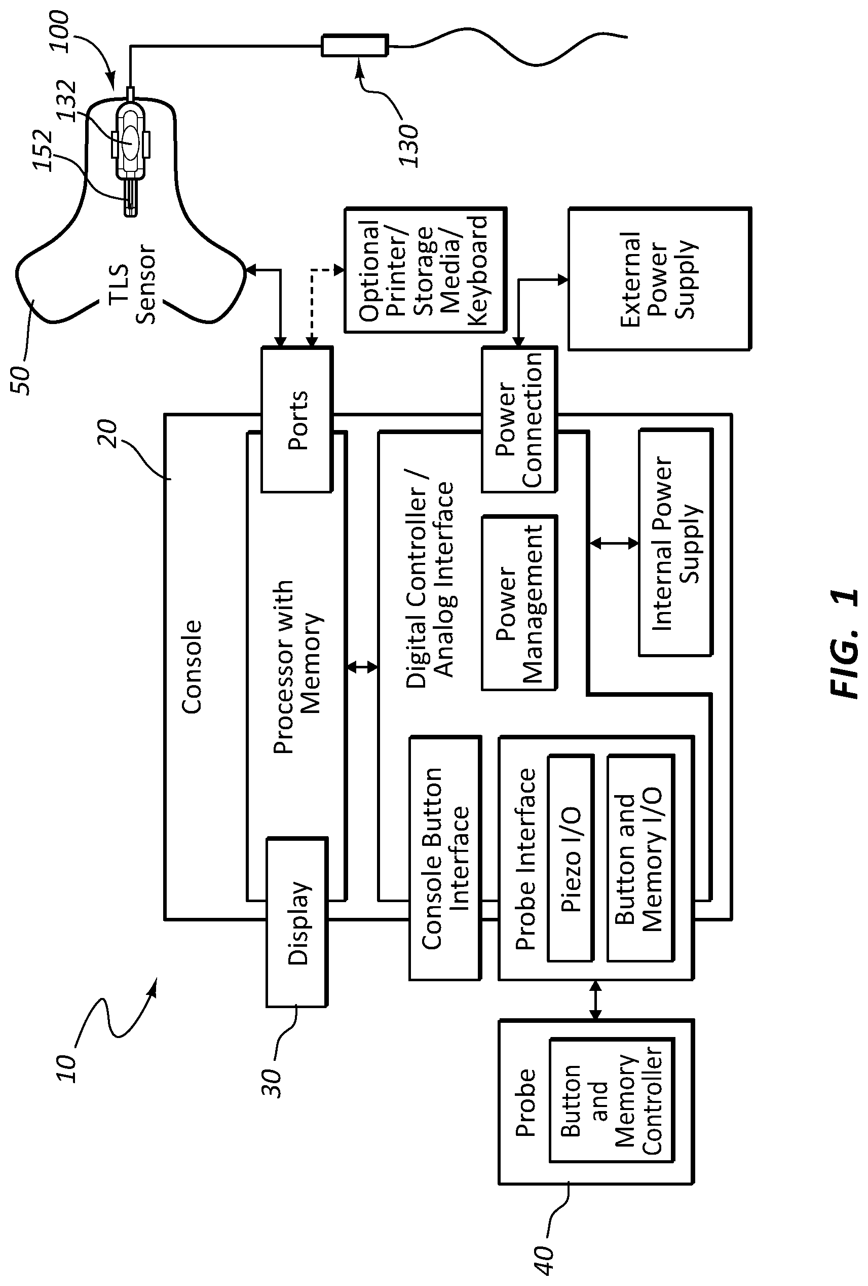
FIG. 1 illustrates a block diagram of a catheter-placement system for placing a catheter in a body of a patient in accordance with some embodiments.
FIG. 2 illustrates the catheter-placement system and the patient in accordance with some embodiments.
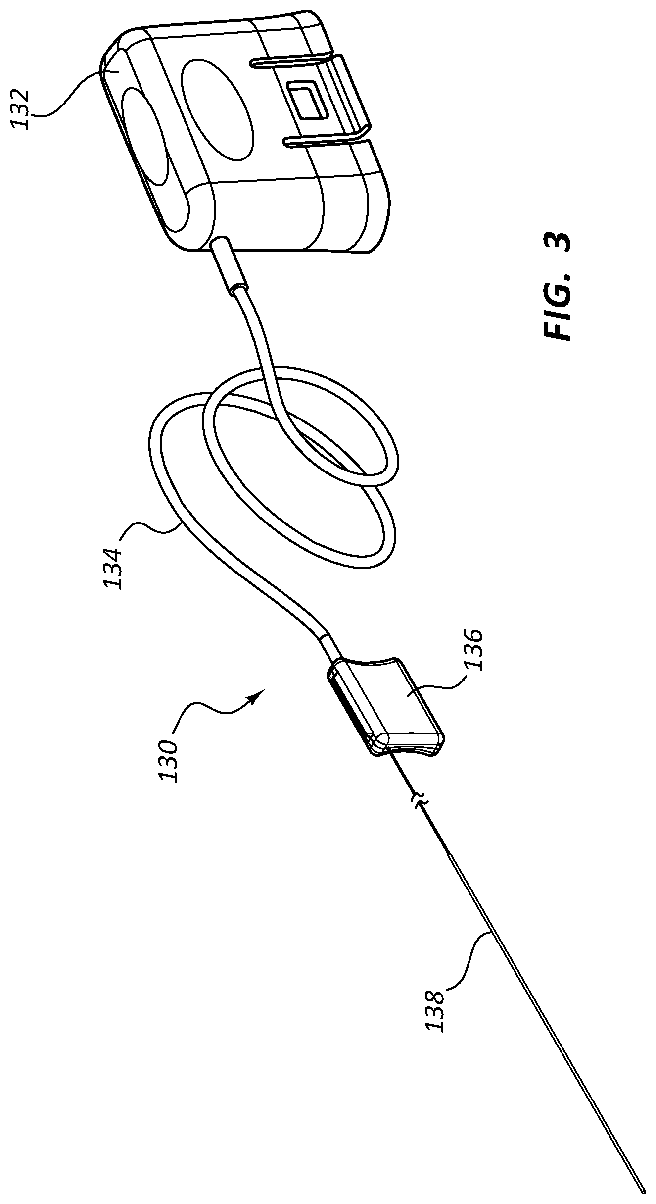
FIG. 3 illustrates a stylet including a tether connector of the catheter-placement system in accordance with some embodiments.
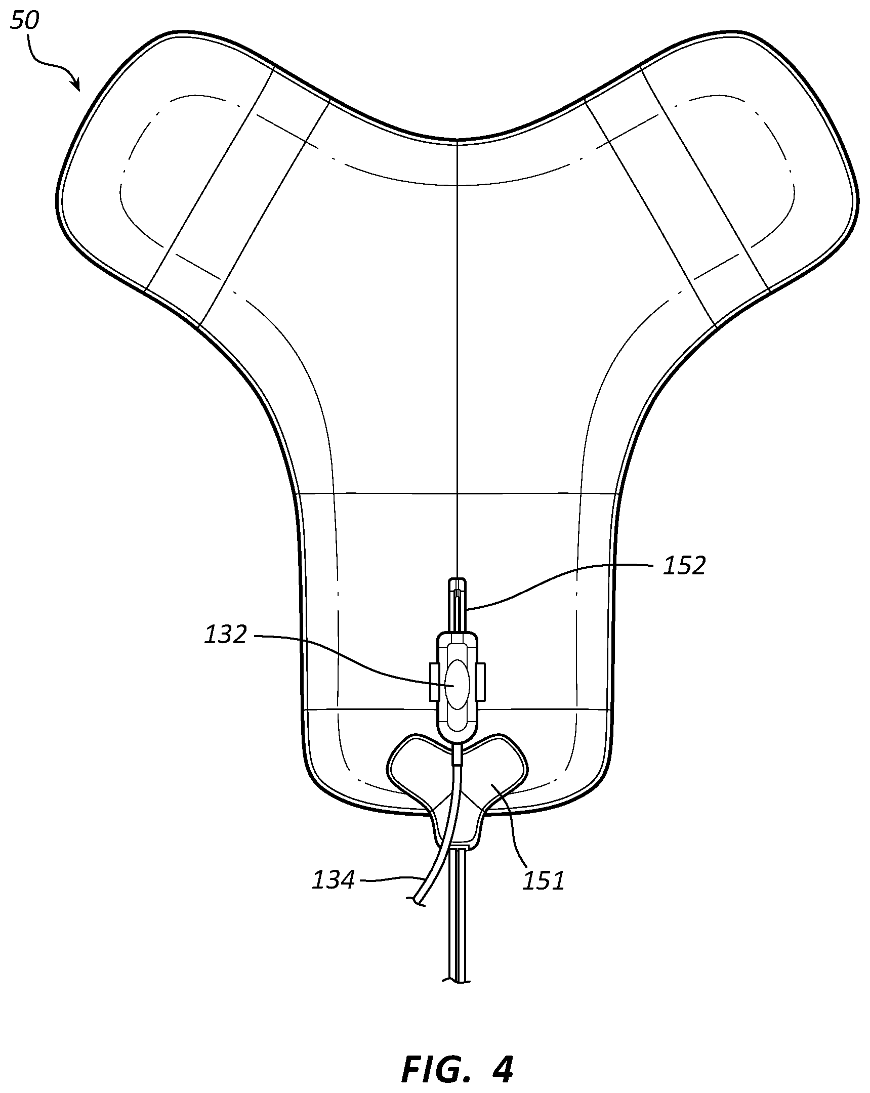
FIG. 4 illustrates a tip-location sensor including a fin connector of the catheter-placement system in accordance with some embodiments.
FIG. 5 illustrates a perspective view of a first connector and a second connector of a connection system in accordance with some embodiments.
FIG. 6 illustrates a view within a housing of the first connector in accordance with some embodiments.
DESCRIPTION
Before some particular embodiments are disclosed in greater detail, it should be understood that the particular embodiments disclosed herein do not limit the scope of the concepts provided herein. It should also be understood that a particular embodiment disclosed herein can have features that can be readily separated from the particular embodiment and optionally combined with or substituted for features of any of a number of other embodiments disclosed herein.
Regarding terms used herein, it should also be understood the terms are for the purpose of describing some particular embodiments, and the terms do not limit the scope of the concepts provided herein. Ordinal numbers (e.g., first, second, third, etc.) are generally used to distinguish or identify different features or steps in a group of features or steps, and do not supply a serial or numerical limitation. For example, "first," "second," and "third" features or steps need not necessarily appear in that order, and the particular embodiments including such features or steps need not necessarily be limited to the three features or steps. Labels such as "left," "right," "top," "bottom," "front," "back," and the like are used for convenience and are not intended to imply, for example, any particular fixed location, orientation, or direction. Instead, such labels are used to reflect, for example, relative location, orientation, or directions. Singular forms of "a," "an," and "the" include plural references unless the context clearly dictates otherwise.
With respect to "proximal," a "proximal portion" or a "proximal end portion" of, for example, a catheter disclosed herein includes a portion of the catheter intended to be near a clinician when the catheter is used on a patient. Likewise, a "proximal length" of, for example, the catheter includes a length of the catheter intended to be near the clinician when the catheter is used on the patient. A "proximal end" of, for example, the catheter includes an end of the catheter intended to be near the clinician when the catheter is used on the patient. The proximal portion, the proximal end portion, or the proximal length of the catheter can include the proximal end of the catheter; however, the proximal portion, the proximal end portion, or the proximal length of the catheter need not include the proximal end of the catheter. That is, unless context suggests otherwise, the proximal portion, the proximal end portion, or the proximal length of the catheter is not a terminal portion or terminal length of the catheter.
With respect to "distal," a "distal portion" or a "distal end portion" of, for example, a catheter disclosed herein includes a portion of the catheter intended to be near or in a patient when the catheter is used on the patient. Likewise, a "distal length" of, for example, the catheter includes a length of the catheter intended to be near or in the patient when the catheter is used on the patient. A "distal end" of, for example, the catheter includes an end of the catheter intended to be near or in the patient when the catheter is used on the patient. The distal portion, the distal end portion, or the distal length of the catheter can include the distal end of the catheter; however, the distal portion, the distal end portion, or the distal length of the catheter need not include the distal end of the catheter. That is, unless context suggests otherwise, the distal portion, the distal end portion, or the distal length of the catheter is not a terminal portion or terminal length of the catheter.
Unless defined otherwise, all technical and scientific terms used herein have the same meaning as commonly understood by those of ordinary skill in the art.
In a typical surgical procedure, a sterile drape is placed over a patient to establish a sterile field, within which the surgical procedure is performed. For example, in a typical catheter-placement procedure, a sterile drape is placed over a patient to establish a sterile field for placement of the catheter. However, there is often a need to breach the sterile barrier in order to make electrical connections between components of various systems without compromising the sterility of the sterile field.
Disclosed herein is a connection system for establishing an electrical connection through a drape and methods thereof that address at least the foregoing need.
For example, a connection system includes, in some embodiments, a first connector and a second connector configured to connect to each other. The first connector includes a first-connector housing, an electrical lead extending from the first-connector housing, and at least a first piercing element within the first-connector housing configured to pierce the drape. The first piercing element is orthogonally connected to the electrical lead. The second connector includes a second-connector housing and at least a first receptacle within the second-connector housing. The first receptacle is configured to form at least a first electrical connection of the one or more electrical connections with the first piercing element when the first connector is disposed over the second connector with the drape therebetween. An example method for establishing one or more electrical connections through the drape with the foregoing connection system is set forth below.
An example catheter-placement system incorporating the connection system will be at least initially described to provide context for the connection system. It should be understood the connection system is not limited to the example catheter-placement system. Indeed, the connection system can be incorporated into any system of various systems having a need to breach a sterile barrier between components of the system in order to make electrical connections therebetween without compromising the sterility of the sterile field.
FIG. 1 illustrates a block diagram of a catheter-placement system 10 for placing a catheter 72 in a body of a patient 70 in accordance with some embodiments. FIG. 2 illustrates the catheter-placement system 10 and the patient 70 in accordance with some embodiments. The catheter-placement system 10 is configured for assisting a clinician in placing the catheter 72 in a vasculature of the patient 70. As shown, the catheter-placement system 10 includes a console 20 including a display 30, an ultrasound probe 40, and a tip-location sensor 50 configured for placement on the patient's chest or some other portion of the patient's body.
FIG. 3 illustrates a stylet 130 including a tether connector 132 of the catheter-placement system 10 in accordance with some embodiments. The stylet 130 is employed with the catheter 72 during insertion of the catheter 72 into the vasculature of the patient 70. The stylet 130 includes a core wire 138 configured to be removably disposed in a lumen of the catheter 72 during a catheter-placement procedure, thereby enabling a distal tip 76 of the catheter 72 to be tracked by the catheter-placement system 10 using one or more of modalities for guiding the catheter 72 to a desired location within the patient's vasculature after insertion of the catheter 72 into a percutaneous insertion site 73 of the patient 70. The one or more modalities include, but are not limited to ultrasound-based imaging of subcutaneous tissue of the patient in preparation for insertion of the catheter 72; magnet-based tracking for determining orientation, advancement direction, and general internal location of the distal tip 76 of the catheter 72; or ECG-based confirmation for confirming the distal tip 76 of the catheter 72 is positioned at a desired location for which ECG lead connector 151 is provided. (See FIG. 4 for ECG lead connector 151.) The stylet 130 further includes a tether 134 proximally extending from a handle 136, the tether 134 terminating at a proximal end thereof with the tether connector 132. The tether connector 132 is configured to mechanically couple and electrically connect with a fin connector 152 of the tip-location sensor 50 as shown in at least FIGS. 1-4 in accordance with some embodiments of a connection system 100.
Additional details for the catheter-placement system 10 shown in FIGS. 1-3 can be found in U.S. Pat. No. 9,649,048, which is incorporated by reference in its entirety into this application.
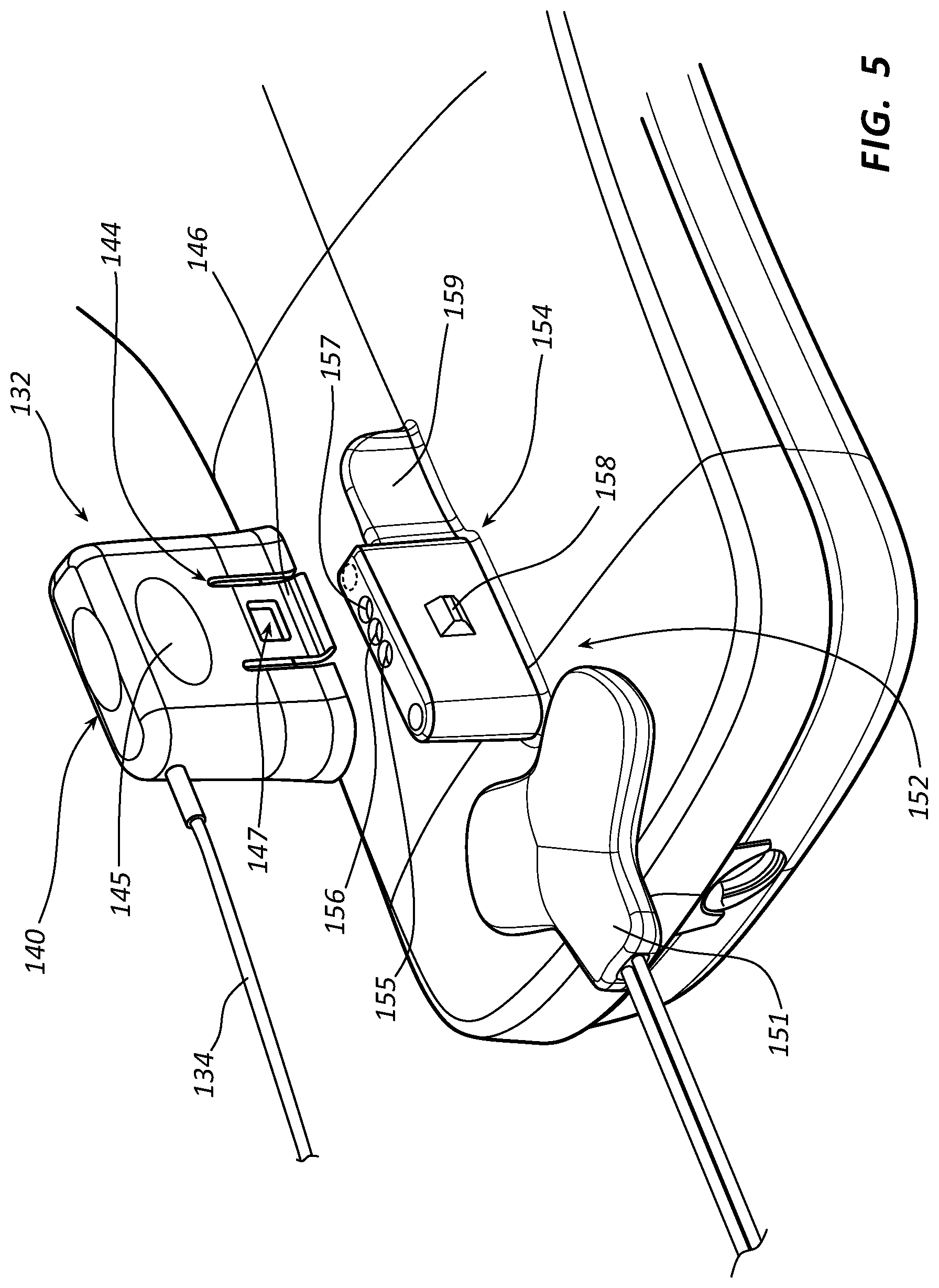
FIG. 4 illustrates the tip-location sensor 50 and the fin connector 152 of the catheter-placement system 10 in accordance with some embodiments. As shown, the fin connector 152 is disposed on the tip-location sensor 50 of the catheter-placement system 10. Again, the tether connector 132 is configured to mechanically couple and electrically connect with the fin connector 152, which enables the catheter-placement system 10 to track the distal tip 76 of the catheter 72. A drape including a sterile drape is configured to provide a sterile field about the patient 70. The drape can be interposed between the tip-location sensor 50 (e.g., under the sterile drape in a non-sterile field) and the stylet 130 (e.g., over the sterile drape in the sterile field). As set forth in more detail below, the tether connector 132 includes at least a first piercing element 142 within a body of the tether connector 132, wherein the first piercing element 142 is configured to pierce the drape and insert into at least a first receptacle 156 of the fin connector 152 to electrically connect the tether connector 132 and the fin connector 152. As best shown in FIG. 5, at least the first receptacle 156 of one or more receptacles in the fin connector 152 is orthogonal to a body of the tip-location sensor 50.
While not shown in FIG. 4, the catheter-placement system 10, or the connection system 100 thereof, can include one or more light-emitting diodes ("LEDs") configured to change from a first state to a second state to indicate success in forming one or more electrical connections between the tether connector 132 and the fin connector 152. The one or more LEDs can include an LED on the tip-location sensor 50, an LED on the tether connector 132, or both of the foregoing LEDs. Upon success in forming the one or more electrical connections between the tether connector 132 and the fin connector 152, each LED of the one or more LEDs can change from a first state of being off to a second state of being on, a first state of being one color (e.g., red) to a second state of being another color (e.g., green), a first state of blinking light to a second state of a solid light, or various combinations thereof. Each LED of the one or more LEDs is configured to change from the first state to the second state upon completion of a dedicated LED circuit for the change of state upon forming the one or more electrical connections. The LED on the tip-location sensor 50 is configured to be bright enough to see through a drape, thus enabling a clinician to see a change from the first state to the second state upon forming one or more electrical connections between the tether connector 132 and the fin connector 152 even when the drape is in place.
In view of the foregoing catheter-placement system 10, the connection system 100 includes a first connector such as the tether connector 132 having the tether 134 and a second connector such as the fin connector 152 configured for mechanically coupling and establishing one or more electrical connections through a sterile drape without compromising the sterile field set up by the sterile drape. Having described the connection system 100 in the context of the catheter-placement system 10, additional details for the first connector and the second connector of the connection system 100 will now be described with the understanding the connection system 100 is not limited to the foregoing catheter-placement system 10. For convenience, the first connector and the second connector of the connection system 100 will now respectively assume the reference numerals 132 and 152. Likewise, an electrical lead of the first connector will now assume the reference numeral 134.
FIG. 5 illustrates a perspective view of the first connector 132 and the second connector 152 of the connection system 100 in accordance with some embodiments. FIG. 6 illustrates a view within a housing 140 of the first connector 132 in accordance with some embodiments.
Again, the connection system 100 includes the first connector 132 and the second connector 152, which are configured for mechanically coupling and establishing one or more electrical connections through a sterile drape without compromising the sterile field set up by the sterile drape. The first connector 132 includes the first-connector housing 140, the electrical lead 134 extending from the first-connector housing 140, and at least a first piercing element 142 having one or more electrical contacts within the first-connector housing 140 configured to pierce the sterile drape. The second connector 152 includes a second-connector housing 154 and at least a first receptacle 156 having one or more electrical contacts within the second-connector housing 154. Each housing of the first-connector housing 140 and the second-connector housing 154 is molded from a medically acceptable polymer such as a thermoplastic.
Beginning with the configuration of the first connector 132 and the second connector 152 of the connection system 100 for mechanically coupling the first connector 132 and the second connector 152, the first-connector housing 140 includes an integrated clip 144 configured to clip the first connector 132 on the second connector 152 with the drape between the first connector 132 and the second connector 152. The integrated clip 144 of the first-connector housing 140 includes a pair of opposing tabs 146 with a corresponding pair of through holes 147, of which through holes 147 only one through hole is shown in FIG. 5. Each tab of the pair of tabs 146 extends from a medial portion of a major side, or long side, of the first-connector housing 140 to a perimeter about a primary opening 148 (see FIG. 6) of the first-connector housing 140. The perimeter about the primary opening 148 of the first-connector housing 140 is shared by all sides of the first-connector housing 140. Because the first-connector housing 140 is molded of a medically acceptable polymer and each tab of the pair of tabs 146 extends from a medial portion of a major side of the first-connector housing 140, each tab of the pair of tabs 146 is flexibly attached to the first-connector housing 140. Each tab of the pair of tabs 146 of the first-connector housing 140 is also flared away from the other tab of the pair of tabs 146 as best shown in FIG. 6.
As a complement to the integrated clip 144 of the first-connector housing 140, the second-connector housing 154 includes a pair of opposing protrusions 158, of which pair of protrusions 158 only one protrusion is shown in FIG. 5. Each protrusion of the pair of protrusions 158 protrudes from a medial portion of a major side, or long side, of the second-connector housing 154. The protrusion in each major side of the second-connector housing 154 is configured to insert in a respective through hole of the pair of tabs 146. In other words, the through hole in each tab of the pair of tabs 146 of the first-connector housing 140 is configured to accept a respective protrusion of the pair of protrusions 158. Each protrusion of the pair of protrusions 158 of the second-connector housing 154 is beveled or chamfered as shown in FIG. 5.
A combination of the flared, flexibly attached pair of tabs 146 of first-connector housing 140 and the beveled or chamfered pair of protrusions 158 of the second-connector housing 154 facilitates disposal of the first connector 132 over the second connector 152 and the resulting mechanical coupling therebetween. Mechanistically, the beveled or chamfered pair of protrusions 158 and the flared, flexibly attached pair of tabs 146 cooperate such that each tab of the pair of tabs 146 is smoothly deflected away from the other tab of the pair of tabs 146 while disposing the first connector 132 over the second connector 152 until the pair of protrusions 158 are respectively seated in the pair of through holes 147 of the pair of tabs 146, thereby mechanically coupling the first connector 132 over the second connector 152. The combination of the flared, flexibly attached pair of tabs 146 of first-connector housing 140 and the beveled or chamfered pair of protrusions 158 of the second-connector housing 154 also facilitates mechanical decoupling and removal of the first connector 132 from the second connector 152. Mechanistically, each tab of the flared pair of tabs 146 is configured to deflect away from the other tab of the pair of tabs 146 by pulling each tab away from the other tab as shown in FIG. 6. Pulling each tab of the pair of tabs 146 away from the other tab of the pair of tabs 146, unseats the pair of protrusions 158 from the pair of through holes 147 of the pair of tabs 146, thereby mechanically decoupling the first connector 132 from the second connector 152 for removing the first connector 132 from the second connector 152.
Minor sides, or short sides, of each housing of the first-connector housing 140 and the second-connector housing 154 are dissimilar. This is best shown in FIG. 6 for the minor sides of the first-connector housing 140. Each minor side of the minor sides of the first-connector housing 140 has a matching minor side of the minor sides of the second-connector housing 154. This enforces a single orientation of the first connector 132 when disposing the first connector 132 over the second connector 152. The minor side of the first-connector housing 140 opposite the minor side including the electrical lead 134 therethrough also includes a notch 149 forming a secondary opening in the first-connector housing 140 configured to accept a fin-like extension 159 of the second-connector housing 154 when disposing the first connector 132 over the second connector 152. This further enforces a single orientation of the first connector 132 when disposing the first connector 132 over the second connector 152.
The first-connector housing 140 includes a pair of opposing finger pads 145, of which pair of finger pads 145 only one finger pad is shown in FIG. 5. The pair of finger pads 145 is configured for pushing the first connector 132 onto the second connector 152 or pulling the first connector 132 off of the second connector 152. Each finger pad of the pair of finger pads 145 includes a depression between the medial portion of the major side of the first-connector housing 140 including the finger pad and a closed end of the first-connector housing 140. As shown in FIG. 5, the closed end of the first-connector housing 140 can also include a finger pad configured for pushing the first connector 132 onto the second connector 152.
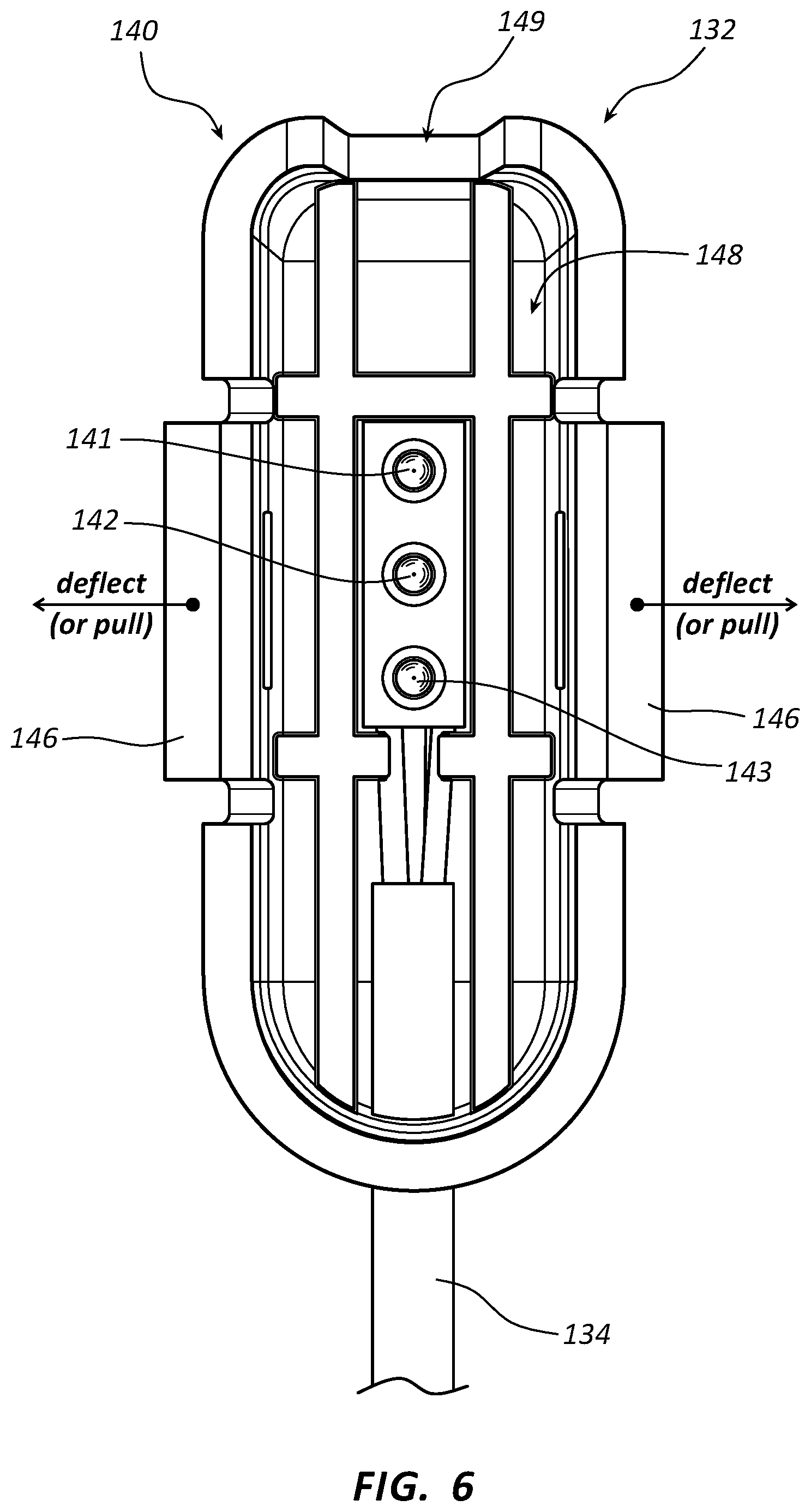
Continuing with the configuration of the first connector 132 and the second connector 152 of the connection system 100 for establishing one or more electrical connections between the first connector 132 and the second connector 152 through a sterile drape, the first piercing element 142 of one or more piercing elements within the first-connector housing 140 is configured to pierce the drape from a sterile side of the drape and insert in the first receptacle 156 of one or more receptacle within the second-connector housing 154, thereby forming at least one electrical connection of the one or more electrical connections when the first connector 132 is disposed over the second connector 152 with the drape therebetween. As set forth below, each of the first piercing element 142 and the first receptacle 156 can include more than one electrical contact. Therefore, more than one electrical connection can be formed when the first piercing element 142 is inserted in the first receptacle 156.
Beginning with an embodiment in which the first piercing element 142 is the only piercing element within the first-connector housing 140, the first piercing element 142 can be a tip-sleeve ("TS") jack plug having a needle-like tip electrical contact and a sleeve electrical contact configured to make at least two of the one or more electrical connections upon insertion of the first piercing element 142 into a complementary jack as the first receptacle 156 within the second-connector housing 154. Alternatively, the first piercing element 142 can be a tip-ring-sleeve ("TR.sub.nS") jack plug having a needle-like tip, n ring electrical contacts with n.gtoreq.1 (N), and a sleeve electrical contact configured to make at least three of the one or more electrical connections upon insertion of the first piercing element 142 into a complementary jack as the first receptacle 156 within the second-connector housing 154. Each additional ring electrical contact of the first piercing element 142 when configured as a TRnS jack plug can be configured to support an additional communication channel for data transfer between the first piercing element 142 and the first receptacle 156. Regardless of whether the first piercing element 142 a TS or TR.sub.nS jack plug, the first piercing element 142 is orthogonally connected to the electrical lead 134. That is, the first piercing element 142 is at an approximately 90.degree. angle to the electrical lead 134 extending from the first-connector housing 140 to which the first piercing element 142 is connected.
Continuing with another embodiment in which the first piercing element 142 is the only piercing element within the first-connector housing 140, the first piercing element 142 can be a blade-like end portion of a printed circuit board having the one or more electrical contacts printed thereon to make the one or more electrical connections upon insertion of the first piercing element 142 into a complementary slot as the first receptacle 156 within the second-connector housing 154. Each additional electrical contact printed on the blade-like end portion of the printed circuit board of the first piercing element 142 can be configured to support an additional communication channel for data transfer between the first piercing element 142 and the first receptacle 156. Like the TS jack plug and TR.sub.nS jack-plug embodiments of the first piercing element 142, the first piercing element 142 is also orthogonally connected to the electrical lead 134 when the first piercing element 142 is configured as a blade-like end portion of a printed circuit board. That is, the first piercing element 142 is at an approximately 90.degree. angle to the electrical lead 134 extending from the first-connector housing 140 to which the first piercing element 142 is connected.
Continuing with the embodiment of FIGS. 5 and 6, in which the first piercing element 142 is one piercing element of a number of piercing elements, the first piercing element 142 can be accompanied by a second piercing element 141 and a third piercing element 143 within the first-connector housing 140, each piercing element of the first, second, and third piercing elements 141, 142, and 143 having one or more electrical contacts. In such embodiments, the first receptacle 156 can be accompanied by a second receptacle 155 and a third receptacle 157 within a second-connector housing 150, each receptacle of the first, second, and third receptacles 155, 156, and 157 having one or more electrical contacts complementary to the one or more electrical contacts of the first, second, and third piercing elements 141, 142, and 143 to form at least three electrical connections when the first connector 132 is disposed over the second connector 152 with the drape therebetween. Each piercing element of the first, second, and third piercing elements 142, 141, and 143 is orthogonally connected to the electrical lead 134. In addition, each piercing element of the first, second, and third piercing elements 142, 141, and 143 is configured to pierce the sterile drape in a different location than the other piercing elements.
While not shown, a drape seal can be disposed within the first connector 132 around a proximal-end portion of any one or more piercing elements of the first, second, and third piercing elements 141, 142, and 143, depending upon the embodiment. The drape seal can be a self-sealing polymeric septum configured as a sticker with a pressure-sensitive adhesive on a drape-facing side of the drape seal configured to adhere to the drape about a piercing thereof. When the first connector 132 and the second connector 152 are disconnected, the drape seal is configured to selectively pull away from the first connector 132, thereby sealing the drape.
Methods for establishing one or more electrical connections through a drape with the connection system 100 include, in some embodiments, placing the drape over the second connector 152 of the connection system 100, the second connector 152 including the second-connector housing 154 having dissimilar minor sides; aligning the first connector 132 of the connection system 100 with the second connector 152, the first connector 132 including the first-connector housing 140 having dissimilar minor sides; disposing the first connector 132 over the second connector 152 with the drape between the first connector 132 and the second connector 152, the drape self-tightening over the second connector 152 during the disposing of the first connector 132 over the second connector 152; piercing a sterile side of the drape with at least the first piercing element 142 within the first-connector housing 140 orthogonally connected to the electrical lead 134 extending from the first-connector housing 140; inserting the first piercing element 142 into at least the first receptacle 156 within the second-connector housing 154; and forming the one or more electrical connections between the first piercing element 142 of the first connector 132 and the first receptacle 156 of the second connector 152. Aligning the first connector 132 of the connection system 100 with the second connector 152 includes matching each minor side of the minor sides of the first-connector housing 140 with the matching minor side of the minor sides of the second-connector housing 154, thereby enforcing a single orientation of the first connector 132 to the second connector 152.
Disposing the first connector 132 over the second connector 152 includes inserting each protrusion of the pair of opposing protrusions 158 protruding from the medial portion of a major side of the second-connector housing 154 into a corresponding through hole of a tab of the pair of opposing tabs 146 extending from the medial portion of a major side of the first-connector housing 140.
Piercing the sterile side of the drape with the first piercing element 142 includes simultaneously piercing the sterile side of the drape in two other locations with the second piercing element 141 and the third piercing element 143 within the first-connector housing 140 orthogonally connected to the electrical lead 134 extending from the first-connector housing 140.
The methods can further include disposing the stylet in a catheter, the first connector 132 being the tether connector 132 coupled to the stylet; and sensing the location of a tip of the catheter in a patient, the second connector 152 being the fin connector 152 of the tip-location sensor 50 on a chest of the patient under the drape. Disposing the first connector 132 over the second connector 152 includes disposing the tether connector 132 over the fin connector 152 with a downward motion substantially orthogonal to the tip-location sensor.
The methods can further include disposing the first connector 132 over the second connector 152 by pushing the first connector 132 onto the second connector 152 using at least the pair of opposing finger pads 145 of the first connector 132. Each finger pad of the pair of finger pads 145 includes the depression between the medial portion of a major side of the first-connector housing 140 including the finger pad and the closed end of the first-connector housing 140.
The methods can further include sealing the drape with the drape seal disposed within the first connector 132 around at least the proximal-end portion of the first piercing element 142. When the first connector 132 and the second connector 152 are disconnected, the drape seal selectively pulls away from the first connector 132, thereby sealing the drape.
Methods can further include confirming success in forming the one or more electrical connections by a change from the first state of the LED on the first connector 132 to the second state of the LED upon forming the one or more electrical connections.
While some particular embodiments have been disclosed herein, and while the particular embodiments have been disclosed in some detail, it is not the intention for the particular embodiments to limit the scope of the concepts provided herein. Additional adaptations or modifications can appear to those of ordinary skill in the art, and, in broader aspects, these adaptations or modifications are encompassed as well. Accordingly, departures may be made from the particular embodiments disclosed herein without departing from the scope of the concepts provided herein.
* * * * *
D00000
D00001
D00002
D00003
D00004
D00005
D00006
XML
uspto.report is an independent third-party trademark research tool that is not affiliated, endorsed, or sponsored by the United States Patent and Trademark Office (USPTO) or any other governmental organization. The information provided by uspto.report is based on publicly available data at the time of writing and is intended for informational purposes only.
While we strive to provide accurate and up-to-date information, we do not guarantee the accuracy, completeness, reliability, or suitability of the information displayed on this site. The use of this site is at your own risk. Any reliance you place on such information is therefore strictly at your own risk.
All official trademark data, including owner information, should be verified by visiting the official USPTO website at www.uspto.gov. This site is not intended to replace professional legal advice and should not be used as a substitute for consulting with a legal professional who is knowledgeable about trademark law.