Neutral host architecture for a distributed antenna system
Lemson , et al. April 5, 2
U.S. patent number 11,297,603 [Application Number 16/406,252] was granted by the patent office on 2022-04-05 for neutral host architecture for a distributed antenna system. This patent grant is currently assigned to DALI WIRELESS, INC.. The grantee listed for this patent is DALI WIRELESS, INC.. Invention is credited to Paul Lemson, Shawn Patrick Stapleton, Sasa Trajkovic.


| United States Patent | 11,297,603 |
| Lemson , et al. | April 5, 2022 |
Neutral host architecture for a distributed antenna system
Abstract
A remote radio head unit (RRU) system for achieving high data rate communications in a Distributed Antenna System is disclosed. The Distributed Antenna System is configured as a Neutral Host enabling multiple operators to exist on one DAS system. The present disclosure enables a remote radio head unit to be field reconfigurable and support multi-modulation schemes (modulation-independent), multi-carriers, multi-frequency bands and multi-channels. As a result, the remote radio head system is particularly suitable for wireless transmission systems, such as base-stations, repeaters, and indoor signal coverage systems.
| Inventors: | Lemson; Paul (Woodinville, WA), Stapleton; Shawn Patrick (Vancouver, CA), Trajkovic; Sasa (Burnaby, CA) | ||||||||||
|---|---|---|---|---|---|---|---|---|---|---|---|
| Applicant: |
|
||||||||||
| Assignee: | DALI WIRELESS, INC. (Menlo
Park, CA) |
||||||||||
| Family ID: | 1000006215943 | ||||||||||
| Appl. No.: | 16/406,252 | ||||||||||
| Filed: | May 8, 2019 |
Prior Publication Data
| Document Identifier | Publication Date | |
|---|---|---|
| US 20200092848 A1 | Mar 19, 2020 | |
Related U.S. Patent Documents
| Application Number | Filing Date | Patent Number | Issue Date | ||
|---|---|---|---|---|---|
| 15786396 | Oct 17, 2017 | 10334567 | |||
| 14479875 | Nov 21, 2017 | 9826508 | |||
| 13211236 | Sep 30, 2014 | 8848766 | |||
| 61374593 | Aug 17, 2010 | ||||
| Current U.S. Class: | 1/1 |
| Current CPC Class: | H04B 1/40 (20130101); H04W 72/04 (20130101); H04B 1/18 (20130101) |
| Current International Class: | H04W 72/04 (20090101); H04B 1/40 (20150101); H04B 1/18 (20060101) |
References Cited [Referenced By]
U.S. Patent Documents
| 4755795 | July 1988 | Page |
| 4999831 | March 1991 | Grace |
| 5457557 | October 1995 | Zarem et al. |
| 5579341 | November 1996 | Smith et al. |
| 5619202 | April 1997 | Wilson et al. |
| 5621730 | April 1997 | Kelley |
| 5627879 | May 1997 | Russell et al. |
| 5644622 | July 1997 | Russell et al. |
| 5748683 | May 1998 | Smith et al. |
| 5794153 | August 1998 | Ariyavisitakul et al. |
| 5810888 | September 1998 | Fenn |
| 5818883 | October 1998 | Smith et al. |
| 5852651 | December 1998 | Fischer et al. |
| 5880863 | March 1999 | Rideout et al. |
| 6005506 | December 1999 | Bazarjani et al. |
| 6005884 | December 1999 | Cook et al. |
| 6014366 | January 2000 | Ichiyoshi |
| 6072364 | June 2000 | Jeckeln et al. |
| 6112086 | August 2000 | Wala |
| 6253094 | June 2001 | Schmutz |
| 6266531 | July 2001 | Zadeh et al. |
| 6353600 | March 2002 | Schwartz et al. |
| 6356369 | March 2002 | Farhan |
| 6373611 | April 2002 | Farhan et al. |
| 6393007 | May 2002 | Haartsen |
| 6493335 | December 2002 | Darcie et al. |
| 6594496 | July 2003 | Schwartz |
| 6625429 | September 2003 | Yamashita |
| 6657993 | December 2003 | Casanova et al. |
| 6697603 | February 2004 | Lovinggood et al. |
| 6704545 | March 2004 | Wala |
| 6724737 | April 2004 | Boyden et al. |
| 6785558 | August 2004 | Stratford et al. |
| 6801767 | October 2004 | Schwartz et al. |
| 6804540 | October 2004 | Shepherd et al. |
| 6826164 | November 2004 | Mani et al. |
| 6831901 | December 2004 | Millar |
| 6836660 | December 2004 | Wala |
| 6963552 | November 2005 | Sabat, Jr. et al. |
| 6980527 | December 2005 | Liu et al. |
| 7102442 | September 2006 | Anderson |
| 7145704 | December 2006 | Islam |
| 7257328 | August 2007 | Levinson et al. |
| 7283519 | October 2007 | Girard |
| 7286507 | October 2007 | Oh et al. |
| 7339891 | March 2008 | Binder et al. |
| 7339897 | March 2008 | Larsson et al. |
| 7362776 | April 2008 | Meier et al. |
| 7489632 | February 2009 | Lakkakorpi |
| 7496367 | February 2009 | Ozturk et al. |
| 7610460 | October 2009 | Watanabe et al. |
| 7634536 | December 2009 | Halasz |
| 7639982 | December 2009 | Wala |
| 7650112 | January 2010 | Utsumi et al. |
| 7765294 | July 2010 | Edwards et al. |
| 7787854 | August 2010 | Conyers et al. |
| 7801038 | September 2010 | Liao et al. |
| 7826369 | November 2010 | Filsfils et al. |
| 7848747 | December 2010 | Wala |
| 7848770 | December 2010 | Scheinert |
| 7855977 | December 2010 | Morrison et al. |
| 8010099 | August 2011 | Ma et al. |
| 8010116 | August 2011 | Scheinert |
| 8032148 | October 2011 | Hettstedt et al. |
| 8036226 | October 2011 | Ma et al. |
| 8098572 | January 2012 | Zhou et al. |
| 8112094 | February 2012 | Wellington |
| 8139492 | March 2012 | Peterson et al. |
| 8213401 | July 2012 | Fischer et al. |
| 8274332 | September 2012 | Cho et al. |
| 8326218 | December 2012 | Wala |
| 8346091 | January 2013 | Kummetz et al. |
| 8346160 | January 2013 | Kummetz |
| 8351877 | January 2013 | Kim et al. |
| 8363628 | January 2013 | Chi et al. |
| 8369272 | February 2013 | Barbaresi et al. |
| 8446530 | May 2013 | Bellers |
| 8451735 | May 2013 | Li |
| 8478331 | July 2013 | Rogers et al. |
| 8520603 | August 2013 | Kozisek et al. |
| 8527003 | September 2013 | Gupta et al. |
| 8532242 | September 2013 | Fischer et al. |
| 8542768 | September 2013 | Kim et al. |
| 8548526 | October 2013 | Schmidt et al. |
| 8577286 | November 2013 | Wala |
| 8583100 | November 2013 | Koziy et al. |
| 8681917 | March 2014 | McAllister et al. |
| 8730786 | May 2014 | Wang et al. |
| 8737300 | May 2014 | Stapleton et al. |
| 8737454 | May 2014 | Wala |
| 8804870 | August 2014 | Kim et al. |
| 8842649 | September 2014 | Liu et al. |
| 8848766 | September 2014 | Lemson et al. |
| 8855489 | October 2014 | Boldi et al. |
| 8958789 | February 2015 | Bauman et al. |
| 9137078 | September 2015 | Stapleton et al. |
| 9148324 | September 2015 | Stapleton et al. |
| 9419714 | August 2016 | Lemson et al. |
| 9419837 | August 2016 | Stapleton et al. |
| 9531473 | December 2016 | Lemson et al. |
| 9820171 | November 2017 | Lemson et al. |
| 9826508 | November 2017 | Lemson et al. |
| 10045314 | August 2018 | Stapleton et al. |
| 10080178 | September 2018 | Stapleton et al. |
| 10159074 | December 2018 | Lemson et al. |
| 10334499 | June 2019 | Stapleton et al. |
| 10334567 | June 2019 | Lemson et al. |
| 2001/0034223 | October 2001 | Rieser et al. |
| 2002/0024398 | February 2002 | Lagerblom et al. |
| 2002/0075906 | June 2002 | Cole et al. |
| 2002/0086675 | July 2002 | Mansour |
| 2002/0093926 | July 2002 | Kilfoyle |
| 2002/0186436 | December 2002 | Mani et al. |
| 2002/0187809 | December 2002 | Mani et al. |
| 2002/0191565 | December 2002 | Mani et al. |
| 2003/0021263 | January 2003 | Lee |
| 2003/0021278 | January 2003 | Domschitz et al. |
| 2003/0137932 | July 2003 | Nishioka et al. |
| 2003/0143947 | July 2003 | Lyu |
| 2003/0181221 | September 2003 | Nguyen |
| 2003/0207680 | November 2003 | Yang et al. |
| 2004/0053624 | March 2004 | Frank et al. |
| 2004/0183672 | September 2004 | Krishan et al. |
| 2005/0041968 | February 2005 | Takahashi |
| 2005/0143091 | June 2005 | Shapira et al. |
| 2005/0152695 | July 2005 | Sulzberger et al. |
| 2005/0157675 | July 2005 | Feder et al. |
| 2005/0174954 | August 2005 | Yun et al. |
| 2005/0181812 | August 2005 | Scheck |
| 2005/0206564 | September 2005 | Mao et al. |
| 2005/0220066 | October 2005 | Wal et al. |
| 2006/0094470 | May 2006 | Wake et al. |
| 2006/0121944 | June 2006 | Buscaglia et al. |
| 2006/0223468 | October 2006 | Toms et al. |
| 2006/0223572 | October 2006 | Hedin et al. |
| 2006/0223578 | October 2006 | Conyers et al. |
| 2006/0227736 | October 2006 | Conyers et al. |
| 2006/0239266 | October 2006 | Babbar et al. |
| 2006/0270366 | November 2006 | Rozenblit et al. |
| 2007/0019598 | January 2007 | Prehofer |
| 2007/0019679 | January 2007 | Scheck et al. |
| 2007/0058742 | March 2007 | Demarco et al. |
| 2007/0064506 | March 2007 | Bauman et al. |
| 2007/0065078 | March 2007 | Jiang |
| 2007/0066234 | March 2007 | Lastinger et al. |
| 2007/0116046 | May 2007 | Liu et al. |
| 2007/0121543 | May 2007 | Kuchibhotla et al. |
| 2007/0147488 | June 2007 | Han |
| 2007/0177552 | August 2007 | Wu et al. |
| 2007/0223614 | September 2007 | Kuchibhotla et al. |
| 2007/0241812 | October 2007 | Yang et al. |
| 2007/0243899 | October 2007 | Hermel et al. |
| 2007/0253389 | November 2007 | Lucidarme et al. |
| 2007/0274279 | November 2007 | Wood et al. |
| 2007/0281643 | December 2007 | Kawai |
| 2008/0045254 | February 2008 | Gupta et al. |
| 2008/0051129 | February 2008 | Abe et al. |
| 2008/0058018 | March 2008 | Scheinert |
| 2008/0069032 | March 2008 | Liu |
| 2008/0070632 | March 2008 | Obuchi et al. |
| 2008/0089689 | April 2008 | Sakama |
| 2008/0107014 | May 2008 | Huang et al. |
| 2008/0119198 | May 2008 | Hettstedt |
| 2008/0146146 | June 2008 | Binder et al. |
| 2008/0152037 | June 2008 | Kim et al. |
| 2008/0165882 | July 2008 | Hedayat et al. |
| 2008/0181182 | July 2008 | Carichner et al. |
| 2008/0181282 | July 2008 | Wala |
| 2008/0225816 | September 2008 | Osterling et al. |
| 2008/0240036 | October 2008 | Liu et al. |
| 2008/0265996 | October 2008 | Kim et al. |
| 2009/0003196 | January 2009 | Capece et al. |
| 2009/0019664 | January 2009 | Abram |
| 2009/0029664 | January 2009 | Batruni |
| 2009/0046586 | February 2009 | Stuart et al. |
| 2009/0060088 | March 2009 | Callard et al. |
| 2009/0060496 | March 2009 | Liu et al. |
| 2009/0061771 | March 2009 | Ma |
| 2009/0082010 | March 2009 | Lee et al. |
| 2009/0146870 | June 2009 | Thome et al. |
| 2009/0153898 | June 2009 | Sato |
| 2009/0154621 | June 2009 | Shapira et al. |
| 2009/0170543 | July 2009 | Mostafa et al. |
| 2009/0180407 | July 2009 | Sabt et al. |
| 2009/0180426 | July 2009 | Sabat et al. |
| 2009/0180462 | July 2009 | Duerdodt et al. |
| 2009/0191891 | July 2009 | Ma et al. |
| 2009/0238566 | September 2009 | Boldi et al. |
| 2009/0247092 | October 2009 | Beaudin et al. |
| 2009/0252094 | October 2009 | Chang et al. |
| 2009/0252136 | October 2009 | Mahany et al. |
| 2009/0252139 | October 2009 | Ludovico et al. |
| 2009/0274048 | November 2009 | Sambhwani et al. |
| 2009/0274085 | November 2009 | Wang et al. |
| 2009/0286484 | November 2009 | Phung et al. |
| 2010/0002661 | January 2010 | Schmidt et al. |
| 2010/0008669 | January 2010 | Rhy et al. |
| 2010/0075678 | March 2010 | Akman et al. |
| 2010/0087227 | April 2010 | Francos et al. |
| 2010/0112981 | May 2010 | Suh et al. |
| 2010/0118921 | May 2010 | Abdelmonem et al. |
| 2010/0128676 | May 2010 | Wu et al. |
| 2010/0130130 | May 2010 | Liu |
| 2010/0136932 | June 2010 | Osterling et al. |
| 2010/0136998 | June 2010 | Lott et al. |
| 2010/0157901 | June 2010 | Sanderovitz et al. |
| 2010/0176885 | July 2010 | Kim et al. |
| 2010/0177759 | July 2010 | Fischer et al. |
| 2010/0177760 | July 2010 | Cannon et al. |
| 2010/0178936 | July 2010 | Wala et al. |
| 2010/0182984 | July 2010 | Herscovici et al. |
| 2010/0202565 | August 2010 | Abbasfar |
| 2010/0238904 | September 2010 | Zhang et al. |
| 2010/0247105 | September 2010 | Yu |
| 2010/0261504 | October 2010 | Lukkarila |
| 2010/0271957 | October 2010 | Stapleton et al. |
| 2010/0271985 | October 2010 | Gabriel |
| 2010/0278530 | November 2010 | Kummetz et al. |
| 2010/0279704 | November 2010 | Vachhani |
| 2010/0291949 | November 2010 | Shapira et al. |
| 2010/0296816 | November 2010 | Larsen |
| 2010/0299173 | November 2010 | Zampiello et al. |
| 2010/0304773 | December 2010 | Ramprashad |
| 2010/0311372 | December 2010 | Bouyaaud et al. |
| 2010/0315978 | December 2010 | Satapathy |
| 2010/0324814 | December 2010 | Wu et al. |
| 2011/0009056 | January 2011 | Hanson et al. |
| 2011/0069657 | March 2011 | Gholmieh et al. |
| 2011/0103309 | May 2011 | Wang et al. |
| 2011/0135013 | June 2011 | Wegener |
| 2011/0135308 | June 2011 | Tarlazzi et al. |
| 2011/0156815 | June 2011 | Kim et al. |
| 2011/0158081 | June 2011 | Wang et al. |
| 2011/0158116 | June 2011 | Tenny et al. |
| 2011/0195673 | August 2011 | Pratt et al. |
| 2011/0223958 | September 2011 | Chen et al. |
| 2011/0237178 | September 2011 | Seki |
| 2011/0241425 | October 2011 | Hunter, Jr. et al. |
| 2011/0249708 | October 2011 | Maca |
| 2011/0255434 | October 2011 | Ylitalo |
| 2011/0281579 | November 2011 | Kummetz |
| 2011/0287791 | November 2011 | Fujishima et al. |
| 2011/0302390 | December 2011 | Copeland et al. |
| 2011/0310810 | December 2011 | Kenington et al. |
| 2011/0310881 | December 2011 | Kenington |
| 2012/0002586 | January 2012 | Gainey et al. |
| 2012/0039254 | February 2012 | Stapleton et al. |
| 2012/0057572 | March 2012 | Evans et al. |
| 2012/0127938 | May 2012 | Lv et al. |
| 2012/0150521 | June 2012 | Balkwill |
| 2012/0154038 | June 2012 | Kim et al. |
| 2012/0155572 | June 2012 | Kim et al. |
| 2012/0206885 | August 2012 | Pan et al. |
| 2012/0281565 | November 2012 | Sauer |
| 2013/0272202 | October 2013 | Stapleton et al. |
| 2014/0126914 | May 2014 | Berlin et al. |
| 2014/0286247 | September 2014 | Lemson et al. |
| 2014/0313884 | October 2014 | Stapleton et al. |
| 2016/0014782 | January 2016 | Stapleton et al. |
| 2016/0080082 | March 2016 | Lemson et al. |
| 2017/0055198 | February 2017 | Stapleton et al. |
| 2017/0070897 | March 2017 | Lemson et al. |
| 2017/0181008 | June 2017 | Fischer |
| 2017/0214420 | July 2017 | Phillips et al. |
| 2017/0238318 | August 2017 | Lemson et al. |
| 2019/0208523 | July 2019 | Lemson et al. |
| 2020/0092787 | March 2020 | Stapleton et al. |
| 2020/0146015 | May 2020 | Lemson et al. |
| 2020/0267732 | August 2020 | Lemson et al. |
| 1484887 | Mar 2004 | CN | |||
| 1652520 | Aug 2005 | CN | |||
| 1774094 | May 2006 | CN | |||
| 1860811 | Nov 2006 | CN | |||
| 100341292 | Oct 2007 | CN | |||
| 201127027 | Oct 2008 | CN | |||
| 101394647 | Mar 2009 | CN | |||
| 101453699 | Jun 2009 | CN | |||
| 101453799 | Jun 2009 | CN | |||
| 101521893 | Sep 2009 | CN | |||
| 101523969 | Sep 2009 | CN | |||
| 201307942 | Sep 2009 | CN | |||
| 100574122 | Dec 2009 | CN | |||
| 101621806 | Jan 2010 | CN | |||
| 101754229 | Jun 2010 | CN | |||
| 101754431 | Jun 2010 | CN | |||
| 102460385 | May 2012 | CN | |||
| 103201958 | Jul 2013 | CN | |||
| 0368673 | May 1990 | EP | |||
| 0642243 | Mar 1995 | EP | |||
| 1118234 | Jul 2001 | EP | |||
| 1566979 | Aug 2005 | EP | |||
| 1750376 | Feb 2007 | EP | |||
| 2430531 | Mar 2012 | EP | |||
| 8527/CHENP/2011 | Mar 2013 | IN | |||
| 1992-207532 | Jul 1992 | JP | |||
| 1993-136724 | Jan 1993 | JP | |||
| 2002-158615 | May 2002 | JP | |||
| 2002-516511 | Jun 2002 | JP | |||
| 2004-147009 | May 2004 | JP | |||
| 2004-153800 | May 2004 | JP | |||
| 2005-072769 | Mar 2005 | JP | |||
| 2007-006163 | Jan 2007 | JP | |||
| 2007-507957 | Mar 2007 | JP | |||
| 2007-523577 | Aug 2007 | JP | |||
| 2007-235738 | Sep 2007 | JP | |||
| 2008-135955 | Jun 2008 | JP | |||
| 2009-147656 | Jul 2009 | JP | |||
| 2009-147956 | Jul 2009 | JP | |||
| 2009-296335 | Dec 2009 | JP | |||
| 2010-166531 | Jul 2010 | JP | |||
| 2012-525093 | Oct 2012 | JP | |||
| 2018-064298 | Apr 2018 | JP | |||
| 10-1996-0702978 | May 1996 | KR | |||
| 10-2003-0061845 | Jul 2003 | KR | |||
| 10-2006-0097712 | Sep 2006 | KR | |||
| 2009-0088083 | Aug 2009 | KR | |||
| 10-2010-017270 | Feb 2010 | KR | |||
| 10-2014-0026321 | Mar 2014 | KR | |||
| 101874655 | Jul 2018 | KR | |||
| 98/24256 | Jun 1998 | WO | |||
| WO 99/60715 | Nov 1999 | WO | |||
| 0019750 | Apr 2000 | WO | |||
| 01/56197 | Aug 2001 | WO | |||
| 02/23956 | Mar 2002 | WO | |||
| WO 02/48862 | Jun 2002 | WO | |||
| WO 02/056481 | Jul 2002 | WO | |||
| 02/102102 | Dec 2002 | WO | |||
| WO 2005/034544 | Apr 2005 | WO | |||
| 2006/040653 | Apr 2006 | WO | |||
| 2007/127543 | Nov 2007 | WO | |||
| 2008/036976 | Mar 2008 | WO | |||
| 2008/146394 | Dec 2008 | WO | |||
| WO 2008/154077 | Dec 2008 | WO | |||
| 2010/008794 | Jan 2010 | WO | |||
| WO 2010/043752 | Apr 2010 | WO | |||
| 2010/124297 | Oct 2010 | WO | |||
| 2010/133942 | Nov 2010 | WO | |||
| 2012/024345 | Feb 2012 | WO | |||
| WO 2012/024343 | Feb 2012 | WO | |||
| WO 2012/024349 | Feb 2012 | WO | |||
Other References
|
US 9,136,967 B2, 09/2015, Fischer et al. (withdrawn) cited by applicant . U.S. Appl. No. 60/877,035, filed Dec. 26, 2006, Kim et al. cited by applicant . U.S. Appl. No. 60/925,603, filed Apr. 23, 2007, Cho et al. cited by applicant . U.S. Appl. No. 61/012,416, filed Dec. 7, 2007, Kim et al. cited by applicant . U.S. Appl. No. 61/041,164, filed Mar. 31, 2008, Kim et al. cited by applicant . U.S. Appl. No. 61/172,642, filed Apr. 24, 2009, Stapleton et al. cited by applicant . U.S. Appl. No. 61/288,838, filed Dec. 21, 2009, Kim et al. cited by applicant . U.S. Appl. No. 61/288,840, filed Dec. 21, 2009, Wang et al. cited by applicant . U.S. Appl. No. 61/288,844, filed Dec. 21, 2009, Kim et al. cited by applicant . U.S. Appl. No. 61/288,847, filed Dec. 21, 2009, Kim et al. cited by applicant . U.S. Appl. No. 61/374,593, filed Aug. 17, 2010, Lemson et al. cited by applicant . U.S. Appl. No. 61/382,836, filed Sep. 14, 2010, Lemson et al. cited by applicant . U.S. Appl. No. 61/439,940, filed Feb. 7, 2011, Stapleton et al. cited by applicant . International Search Report far International Application No. PCT/US2011/047995, dated Dec. 22, 2011. cited by applicant . Written Opinion for International Application No. PCT/US2011/047995, dated Dec. 22, 2011. cited by applicant . International Preliminary Report on Patentability for International Application No. PCT/US2011/047995, dated Aug. 30, 2012. cited by applicant . International Search Report for International Application No. PCT/US2011/048004, dated Jan. 5, 2012. cited by applicant . Written Opinion for International Application No. PCT/US2011/048004, dated Jan. 5, 2012. cited by applicant . Office Action (Including Translation) for Chinese Patent Application No. 201180050053.9, dated Feb. 25, 2015. cited by applicant . Office Action (Including Translation) for Chinese Patent Application No. 201180050053.9, dated Nov. 9, 2015. cited by applicant . Office Action (Including Translation) for Chinese Patent Application No. 201180050053.9, dated Apr. 20, 2016. cited by applicant . Office Action (Including Translation) for Chinese Patent Application No. 201180050053.9, dated Dec. 6, 2016. cited by applicant . Notification of Grant Patent Right for Invention (Including Translation) for Chinese Patent Application No. 201180050053.9, dated Jun. 29, 2017. cited by applicant . Office Action for Chinese Patent Application No. 201710791641.7, dated Apr. 28, 2019. cited by applicant . Notification of Grant of Patent for Invention (Including Translation) for Chinese Patent Application No. 201710791641.7, dated Dec. 4, 2019. cited by applicant . European Search Report for European Application No. 11818694.9, dated Apr. 11, 2017. cited by applicant . Office Action for European Application No. 11818694.9, dated Feb. 13, 2018. cited by applicant . Office Action for European Application No. 11818694.9, dated Nov. 12, 2018. cited by applicant . Summons to Attend Oral Proceedings Pursuant to Rule 115(1) EPC for European Application No. 11818694.9, dated Sep. 30, 2019. cited by applicant . European Search Report for European Application No. 20160422.0, dated Mar. 25, 2020. cited by applicant . Notice of Decision to Grant for Indonesian Patent Application No. W00201300982, dated Nov. 9, 2017. cited by applicant . Examination Report for Indian Patent Application No. 1764/CHENP/2013, dated Jun. 14, 2019. cited by applicant . Office Action (Including Translation) for Japanese Patent Application No. 2013-524941, dated Jun. 23, 2015. cited by applicant . Decision to Grant (Including Translation) for Japanese Patent Application No. 2013-524941, dated Mar. 1, 2016. cited by applicant . Office Action (Including Translation) for Korean Application No. 10-2013-7006774, dated Oct. 11, 2015. cited by applicant . Notice of Allowance (Including Translation) for Korean Application No. 10-2013-7006774, dated Jun. 29, 2016. cited by applicant . Office Action (Including Translation) for Korean Application No. 10-2016-7026899, dated Jan. 19, 2017. cited by applicant . Notice of Grant (Including Translation) for Korean Application No. 10-2016-7026899, dated Nov. 28, 2017. cited by applicant . Office Action (Including Translation) for Korean Application No. 10-2018-7005866, dated May 30, 2018. cited by applicant . Office Action for U.S. Appl. No. 13/211,236, dated Oct. 23, 2012. cited by applicant . Office Action for U.S. Appl. No. 13/211,236, dated Mar. 29, 2013. cited by applicant . Notice of Allowance for U.S. Appl. No. 13/211,236, dated May 29, 2014. cited by applicant . Office Action for U.S. Appl. No. 14/479,875, dated May 6, 2016. cited by applicant . Office Action for U.S. Appl. No. 14/4/9,875, dated Jan. 20, 2017. cited by applicant . Notice of Allowance for U.S. Appl. No. 14/479,875, dated Jul. 19, 2017. cited by applicant . Office Action for U.S. Appl. No. 15/786,396 dated Jul. 12, 2018. cited by applicant . Notice of Allowance for U.S. Appl. No. 15/786,396 dated Feb. 8, 2019. cited by applicant . Notice of Allowance received for U.S. Appl. No. 16/901,116, dated Apr. 21, 2021, 50 pages. cited by applicant . Notice of Allowance received for U.S. Appl. No. 16/410,860, dated Jan. 7, 2021, 54 pages. cited by applicant . BICSI, "Network Design Basics for Cabling Professionals", McGraw-Hill, New York, NY, USA, 2002, 393 pages. cited by applicant . Common Public Radio Interface {CPRI) Specification V1 .4, dated Mar. 31, 2006, downloaded from http://www.cpri.info/spec.html on Mar. 28, 2017, 64 pages. cited by applicant . Common Public Radio Interface {CPRI) Specification V2.1 , dated Mar. 31, 2006, downloaded from http://www.cpri.info/spec.html on Mar. 28, 2017, 76 pages. cited by applicant . Common Public Radio Interface {CPRI) Specification V3.0, dated Oct. 20, 2006, downloaded from http://www.cpri.info/spec.html on Mar. 28, 2017, 89 pages. cited by applicant . Common Public Radio Interface {CPRI) Specification V4.0, dated Jun. 30, 2008, downloaded from http://www.cpri.info/spec.html on Mar. 28, 2017, 96 pages. cited by applicant . Common Public Radio Interface {CPRI) Specification V4.1 , dated Feb. 18, 2009, downloaded from http://www.cpri.info/spec.html on Mar. 28, 2017, 109 pages. cited by applicant . Grundmann et al., "An empirical comparison of a distributed antenna microcell system versus a single antenna microcell system for indooor spread spectrum communications at 1.8 GHz", ICUPC Conference, 1993, 5 pages. cited by applicant . Zhaohui et al., "A rake type receiver structure for CDMA mobile communication systems using antenna arrays", IEEE, 1996, pp. 528-530. cited by applicant . Kester, Walt, Mastering The Mix In Signal Processing, Mixed-Signal Design Seminar, Analog Devices, Inc., 1991, 3 pages. cited by applicant . Grace, Martin K., "Synchronous quantized subcarrier multiplexing for transport of video, voice, and data", IEEE Journal on Selected Areas in Communications, vol. 8, No. 7, Sep. 1990, pp. 1351-1358. cited by applicant . Wala, Philip M., "A new microcell architecture using digital optical transport", IEEE, 1993, pp. 585-588. cited by applicant . Crofut, Walter, "Remote monitoring of wirelss base stations", Jun. 1, 1998, http://urgentcomm.com/prinUmag/remote-monitoring-wireless-base-stat- ions, downloded on Mar. 13, 2017, 4 pages. cited by applicant . Cyr et al., "The digital age is here, Digital radio frequency transport enhances cellular network performance", Jul. 4, 1993, Telephony, pp. 20-24. cited by applicant . CityCell 824, "Remote Site Manual, How to use it, Preliminary Version"; Feb. 1, 1993, 237 pages. cited by applicant . Cheun, Kyungwhoon, "Performance of direct-sequence spread-spectrum rake receives with random spreading sequences", IEEE Transactions On Communication, vol. 45, No. 9, Sep. 9, 1997, pp. 1130-1143. cited by applicant . Brunner et al., "On space-time rake receiver structure for WCDMA", 1999, IEEE, pp. 1546-1551. cited by applicant . Graf, Rudolf F., "Modern Dictionary of Electronics, 7th Ed.", Newnes publishing, 1999, 9 pages. cited by applicant . Introduction to Receivers" Available at http://weww.ece.ucsb.eduHong/ece145a/lntroduction_to_Receivers.pdf" downloaded Jun. 15, 2017, 28 pages. cited by applicant . Pereira, Stephen M., "Standardizing Digital IF Data Transfer with VITA 49", RTC Magazine, downloaded Jun. 15, 2017 from http://rtcmagazine.com/articles/view/100460, 5 pages. cited by applicant . Lan et al., "GSM Co-Channel and Adjacent Channel Interference Analysis and Optimization", Tsinghua Science And Technology, ISSN 1007-0214 04/12, Dec. 2011, vol. 16, No. 5, pp. 583-588. cited by applicant . Laplante, Phillip A. "Comprehensive Dictionary of Electrical Engineering" IEEE Press; CRC Press LLC, 1999; 4 pages. cited by applicant . Microsoft Press "Computer Dictionary: The Comprehensive Standard for Business, School, Library, and Home", 1991, Microsoft Press, ISBN 1-55615-231-0, 6 pages. cited by applicant . Wiley Electrical and Electronics Engineering Dictionary, 2004, Wiley & Sons, Inc., 7 pages. cited by applicant . Parker, Sybil P. "McGraw-Hill Dictionary of Science and Technical Terms: 5th Edition" McGraw-Hill, Inc. 1994; 6 pages. cited by applicant . Horak, Ray, "Telecommunications and Data Communications Handbook", 2007, Wiley & Sons, Inc., 55 pages. cited by applicant . Spurgeon, Charles E., "Ethernet, The Definitive Guide", 2000, O'reilly & Assoc., Inc., 112 pages. cited by applicant . ADC Digivance "Street-Level Coverage Solution (SCS)", Aug. 2005, 8 pages. cited by applicant . ADC Digivance "Street-Level Coverage Solution System with Version 3.01 EMS Software Operation and Maintenance Manual", ADCP-75-187, Issue 1, Sep. 2005, 78 pages. cited by applicant . ADC Digivance "CXD Multi-Band Distributed Antenna System Installation and Operation Manual", ADCP-75-192 Preliminary Issue D; Oct. 2005, 122 pages. cited by applicant . ADC Digivance "Street-Level Coverage Solution 800 MHz, 1900 MHz, and 800/900 MHz SMR System Operation and Maintenance Manual" ADCP-75-187, Preliminary Issue 1B, Nov. 2005, 88 pages. cited by applicant . ADC Digivance "CXD Multi-Band Distributed Antenna System Operation Manual", ADCP-75-192, Issue 1, Dec. 2005, 130 pages. cited by applicant . ADC Digivance "Indoor Coverage Solution 800 MHz Single- or Multi-Mode Fiber System Installation and Operation Manual", ADC-75-130, Preliminary Issue 3C, Aug. 2006, 78 pages. cited by applicant . ADC Digivance "NXD Radio Access Node (RAN) Installation and Maintenance Manual", ADCP-75-210, Issue 1, Nov. 2006, 84 pages. cited by applicant . ADC "ADC FlexWave Prism Element Management System 6.0", User Manual, ADCP-77-152, Issue 1, Mar. 2010, 308 pages. cited by applicant . ADC "ADC FlexWave Prism Element Management System 7.1", User Manual, ADCP-77-177, Issue 1, Jul. 2011, 350 pages. cited by applicant . ADC "ADC FlexWave Prism 6.0", Troubleshooting Guide, ADCP-77-074, Issue 1, Oct. 2010, 62 pages. cited by applicant . ADC "ADC FlexWave Prism Remote RF Module", Installation Instructions, ADCP-77-079, Issue 2, Mar. 2010, 30 pages. cited by applicant . ADC "ADC FlexWave Prism Remote RF Module", Installation Instructions, ADCP-77-079, Issue 3, Jul. 2011, 32 pages. cited by applicant . ADC "ADC FlexWave Prism Remote 40W Rf Module", Installation Instructions, ADCP-77-162, Issue 1, Mar. 2010, 26 pages. cited by applicant . ADC "ADC FlexWave Prism Remote Unit", Installation Guide, ADCP-77-072, Issue 4, Jul. 2011, 44 pages. cited by applicant . ADC "ADC FlexWave Prism Remote Unit", Installation Guide, ADCP-77-072, Issue 5, Nov. 2011, 44 pages. cited by applicant . ADC "FlexWave Prism Flexible Outdoor Wireless Coverage and Capacity", 106969AE, Oct. 2008, 8 pages. cited by applicant . ADC "ADC FlexWave Prism Host, Remote and EMS 5.1", System Reference, ADCP-77-073, Issue 2, Nov. 2009, 364 pages. cited by applicant . ADC "FlexWave URH Operation and Maintenance Manual--Preliminary", 2007, 7 pages. cited by applicant . ADC "ADC FlexWave Universal Radio Head (URH) Remote Unit Installation Instructions", ADCP-75-34 7, Issue 1, Apr. 2008, 32 pages. cited by applicant . ADC "ADC FlexWave Universal Radio Head (URH) Host Unit Installation Instructions", ADCP-75-348, Issue 1, Apr. 2008, 44 pages. cited by applicant . ADC FlexWave User Manual, "FlexWave Web-Based Element Management System for Universal Radio Head System", Version 2/Version 3, ADCP-75-352, Issue 1, Aug. 2008, 160 pages. cited by applicant . Das et al., "A Dynamic Load balancing Strategy for Channel Assignment Using Selective Borrowing in Cellular Mobile Environment", Wireless Networks, vol. 3,1997, pp. 333-347. cited by applicant . ETSI TS 125 101 V.3.11.0 "Universal Mobile Telecommunications System (UMTS); UE Radio Transmission and Reception (FDD) (3GPP TS 25.101 Version 3.11.0 Release 1999", Jun. 2002, 69 pages. cited by applicant . ETSI TS 125 423 V5.6.0 "Universal Mobile Telecommunications System (UMTS); UTRAN lur Interface Radio Network Subsystem Application Part (RNSAP) Signaling (3GPP TS 25.423 version 5.6.0 Release 5)", Jun. 2003, 559 pages. cited by applicant . Hollis et al., "The Theory of Digital Down Conversion", Hunt Engineering, Jun. 26, 2003, 6 pages. cited by applicant . Information Sciences Institute, University of Southern California, "DOD Standard Internet Protocol", RFC 760, Jan. 1980, 46 pages. cited by applicant . Information Sciences Institute, University of Southern California, "Internet Protocol; DARPA Internet Program; Protocol Specification", RFC 791, Sep. 1981, 49 pages. cited by applicant . OBSAI "Open Base Station Architecture Initiative: BTS System Reference Document", Version 2.0; Apr. 27, 2006, 151 pages. cited by applicant . OBSAI "Open Base Station Architecture Initiative: Reference Point 3 Specification" Version 3.1, Nov. 13, 2006, 116 pages. cited by applicant . OBSAI "Open Base Station Architecture Initiative: Reference Point 3 Specification", Version 4.1, Jul. 14, 2008, pp. 1-144. cited by applicant . Notice of Allowance received for U.S. Appl. No. 17/000,188, dated Jan. 19, 2021, 103 pages. cited by applicant . Non-Final Office Action received for U.S. Appl. No. 16/592,615, dated Feb. 3, 2021, 59 pages. cited by applicant . Final Office Action received for U.S. Appl. No. 16/737,419, dated Mar. 11, 2021, 41 pages. cited by applicant . Notice of Allowance received for U.S. Appl. No. 16/777,306, dated Jan. 25, 2021, 49 pages. cited by applicant . Extended European Search Report for application No. 20196761.9 dated Dec. 23, 2020. cited by applicant . Notice of Allowance received for U.S. Appl. No. 16/777,306, dated May 17, 2021, 24 pages. cited by applicant . Notice of Allowance received for U.S. Appl. No. 17/000,188 dated Nov. 25, 2020, 42 pages. cited by applicant . Notice of Allowance received for U.S. Appl. No. 16/944,028, dated Apr. 7, 2021, 31 pages. cited by applicant . Notice of Allowance received for U.S. Appl. No. 16/901,116, dated Jun. 23, 2021, 56 pages. cited by applicant . Notice of Allowance received for U.S. Appl. No. 16/592,615, dated Sep. 23, 2021, 20 pages. cited by applicant . Non Final Office Action received for U.S. Appl. No. 17/234,482, dated Sep. 15, 2021, 55 pages. cited by applicant . Common Public Radio Interface {CPRI) Specification V4.1 , dated Feb. 19, 2009, downloaded from http://www.cpri.info/spec.html on Mar. 28, 2017, 109 pages. cited by applicant . Graf, Rudolf F., "Modem Dictionary of Electronics, 7th Ed.", Newnes publishing, 1999, 9 pages. cited by applicant . Introduction to Receivers" Available at http://weww.ece.ucsb.eduHong/ece145a/lntroduction_to_Receivers.pdr" downloaded Jun. 15, 2017, 28 pages. cited by applicant . Niley Electrical and Electronics Engineering Dictionary, 2004, Wiley & Sons, Inc., 7 pages. cited by applicant. |
Primary Examiner: Nguyen; Brian D
Attorney, Agent or Firm: Artegis Law Group, LLP
Parent Case Text
RELATED APPLICATIONS
This application is a continuation of U.S. patent application Ser. No. 15/786,396, filed Oct. 17, 2017, now U.S. Pat. No. 10,334,567, which is a continuation of U.S. patent application Ser. No. 14/479,875, filed Sep. 8, 2014, now U.S. Pat. No. 9,826,508; which is a continuation of U.S. patent application Ser. No. 13/211,236, filed Aug. 16, 2011, now U.S. Pat. No. 8,848,766; which claims priority to U.S. Provisional Patent Application No. 61/374,593, filed on Aug. 17, 2010. The disclosures of each are hereby incorporated by reference in their entirety for all purposes.
Claims
What is claimed is:
1. A remotely reconfigurable remote radio head unit (RRU) for transporting radio frequency signals, the remotely reconfigurable remote radio head unit comprising: a plurality of band modules, an access module coupled to the plurality of band modules, comprising: a transceiver configured to convert a downlink signal to a downlink electronic signal associated with a first data rate; a multiplexer/demultiplexer coupled to the transceiver and configured to convert the downlink electronic signal associated with the first data rate to a plurality of signals, each signal of the plurality of signals having a second data rate less than the first data rate; a module coupled to the multiplexer/demultiplexer, wherein the module comprises: a framer/deframer configured to: receive the plurality of signals at the second data rate; frame RRU data from the plurality of signals at the second data rate for an individual RRU band module of the plurality of RRU band modules; and route the framed RRU data to the individual RRU band module of the plurality of RRU band modules; and a plurality of RRU outputs coupled to the module and configured to provide the framed RRU data to the plurality of RRU band modules.
2. The RRU of claim 1, wherein the module comprises a field programmable gate array.
3. The RRU of claim 1, wherein the access module has separately reconfigurable parameters associated with each of the plurality of RRU band modules.
4. The RRU of claim 3, wherein the separately reconfigurable parameters comprise at least one of an operator, frequency, or carrier.
5. The RRU of claim 3, further comprising an Ethernet switch for communicating the separately reconfigurable parameters to the plurality of RRU band modules.
6. The RRU of claim 1, wherein the transceiver further comprises a small form factor pluggable optic transceiver configured to operate on at least two distinct wavelengths.
7. The RRU of claim 1, further comprising a software control operable to provide a Flexible Simulcast capability.
8. The RRU of claim 1, wherein the downlink signal is an analog optical signal.
9. The RRU of claim 1, wherein each RRU band module of the plurality of RRU band modules is PCMCIA compatible.
10. The RRU of claim 1, wherein one or more RRU band modules of the plurality of RRU band modules has a diversity receive branch.
11. The RRU of claim 1, wherein the RRU receives power over Ethernet.
12. A remotely reconfigurable remote radio head unit (RRU) comprising: a plurality of RRU band modules; and an access module coupled to the plurality of RRU band modules comprising: an RF-to-Digital interface configured to output a downlink signal associated with a first data rate; a multiplexer/demultiplexer coupled to the RF-to-Digital interface and configured to convert the downlink signal associated with the first data rate to a plurality of signals, each signal of the plurality of signals having a second data rate less than the first data rate; a module coupled to the multiplexer/demultiplexer, wherein the module comprises: a framer/deframer configured to: receive the plurality of signals at the second data rate; frame RRU data from the plurality of signals at the second data rate for an individual RRU band module of the plurality of RRU band modules; and route the framed RRU data to the individual RRU band module of the plurality of RRU band modules; and a plurality of RRU outputs coupled to the module and configured to provide the framed RRU data to the plurality of RRU band modules.
13. The RRU of claim 12, wherein the access module has separately reconfigurable parameters associated with each of the plurality of RRU band modules.
14. The RRU of claim 13, wherein the separately reconfigurable parameters comprise at least one of an operator, frequency, or carrier.
15. The RRU of claim 13, further comprising an Ethernet switch for communicating the separately reconfigurable parameters to the plurality of RRU band modules.
16. The RRU of claim 12, further comprising a software control operable to provide a Flexible Simulcast capability.
17. The RRU of claim 12, wherein each RRU band module of the plurality of RRU band modules is PCMCIA compatible.
18. The RRU of claim 12, wherein one or more RRU band modules of the plurality of RRU band modules has a diversity receive branch.
19. The RRU of claim 12, wherein the RRU receives power over Ethernet.
Description
TECHNICAL FIELD
The present invention generally relates to wireless communication systems employing Distributed Antenna Systems (DAS). More specifically, the present invention relates to a DAS which is part of a distributed wireless network base station in which all radio-related functions that provide network coverage and/or capacity for a given area are contained in a small single unit that can be deployed in a location remote from the remaining distributed wireless network base station unit or units which are not performing radio-related functions. Multi-mode radios capable of operating according to GSM, HSPA, LTE, TD-SCDMA, UMTS and WiMAX standards with advanced software configurability are features in the deployment of more flexible and energy-efficient radio networks. The present invention can also serve multiple operators and multi-frequency bands per operator within a single DAS to reduce the costs associated with radio network equipment and radio network deployment.
BACKGROUND OF THE INVENTION
Wireless and mobile network operators face the continuing challenge of building networks that effectively manage high data-traffic growth rates. Mobility and an increased level of multimedia content for end users requires end-to-end network adaptations that support both new services and the increased demand for broadband and flat-rate Internet access. In addition, network operators must consider the most cost-effective evolution of the networks towards 4G and other advanced network capabilities. Wireless and mobile technology standards are evolving towards higher bandwidth requirements for both peak rates and cell throughput growth. The latest standards supporting these higher bandwidth requirements are HSPA+, WiMAX, TD-SCDMA and LTE. The network upgrades required to deploy networks based on these standards must deal with the limited availability of new spectrum, leverage existing spectrum, and ensure operation of all desired wireless technology standards. The processes of scarce resource optimization while ensuring a future-proof implementation must both take place at the same time during the transition phase, which usually spans many years and thus can encompass numerous future developments. Distributed open base station architecture concepts have evolved in parallel with the evolution of the various technology standards to provide a flexible, lower-cost, and more scalable modular environment for managing the radio access evolution. Such advanced base station architectures can generally be appreciated from FIG. 1 [PRIOR ART], which shows an architecture for a prior art Distributed Wireless Network Base Station. In FIG. 1, 100 is a depiction of a Distributed Wireless Network Base Station. The Base Transceiver Station (BTS) or Digital Access Unit (DAU) 101 coordinates the communication between the Remote Radio Head Units 102, 103 and the Base Station Controller (BSC). The BTS communicates with multiple Remote Radio Heads via optical fiber. For example, the Open Base Station Architecture Initiative (OBSAI), the Common Public Radio Interface (CPRI), and the IR Interface standards introduced publicly-defined interfaces separating the Base Transceiver Station (BTS) or Digital Access Unit and the remote radio head unit (RRU) parts of a base station by employing optical fiber transport.
The RRU concept constitutes a fundamental part of an advanced state-of-the-art base station architecture. RRU-based system implementation is driven by the need to achieve consistent reductions in both Capital Expenses (CAPEX) and Operating Expenses (OPEX), and enable a more optimized, energy-efficient, and greener base deployment. An existing application employs an architecture where a 2G/3G/4G base station is connected to RRUs over multiple optical fibers. Either CPRI, OBSAI or IR Interfaces may be used to carry RF data to the RRUs to cover a sectorized radio network coverage area corresponding to a radio cell site. A typical implementation for a three-sector cell employs three RRU's. The RRU incorporates a large number of digital interfacing and processing functions. However, commercially available RRU's are power inefficient, costly and inflexible. Their poor DC-to-RF power conversion insures that they will need to have a large mechanical housing to help dissipate the heat generated. The demands from wireless service providers for future RRU's also includes greater flexibility in the RRU platform, which is not presently available. As standards evolve, there will be a need for multi-band RRUs that can accommodate two or more operators using a single wideband power amplifier. Co-locating multiple operators in one DAS system would reduce the infrastructure costs and centralize the Remote Monitoring Function of multiple Operators on the Network. To accommodate multiple operators and multiple bands per operator would require a very high optical data rate to the RRUs which is not achievable with prior art designs.
BRIEF SUMMARY OF THE INVENTION
The present invention substantially overcomes the limitations of the prior art discussed above. Accordingly, it is an object of the present invention to provide a high performance, cost-effective DAS system, architecture and method for an RRU-based approach which enables each of multiple operators to use multi-frequency bands. The present disclosure enables a RRU to be field reconfigurable, as presented in U.S. Patent application U.S. 61/172,642 (DW 1016P), filed Apr. 24, 2009, entitled Remotely Reconfigurable Power Amplifier System and Method, U.S. patent application Ser. No. 12/108,502 (DW1011U), filed Apr. 23, 2008, entitled Digital Hybrid Mode Power Amplifier System, U.S. Patent application U.S. 61/288,838 (DW1018P), filed Dec. 21, 2009, entitled Multi-band Wideband Power Amplifier Digital Predistortion System, U.S. Patent application U.S. 61/288,840 (DW1019P), filed Dec. 21, 2009, entitled Remote Radio Head Unit with Wideband Power Amplifier and Method, U.S. Patent application U.S. 61/288,844 (DW1020P), filed Dec. 21, 2009, entitled Modulation Agnostic Digital Hybrid Mode Power Amplifier System, and U.S. Patent application U.S. 61/288,847 (DW1021P), filed Dec. 21, 2009, entitled High Efficiency Remotely Reconfigurable Remote Radio Head Unit System and Method for Wireless Communications incorporated herein by reference. In addition, the system and method of the present invention supports multi-modulation schemes (modulation-independent), multi-carriers, multi-frequency bands, and multi-channels. To achieve the above objects, the present invention maximizes the data rate to the Remote Radio Head Unit in a cost effective architecture. FIGS. 2 and 3 depict a low power RRU and high power RRU. The RRUs depicted in FIGS. 2 and 3 can be extended to a multi-band and multi-channel configuration. Multi-band implies more than two frequency bands and multi channel implies more than one output to an antenna system. Various embodiments of the invention are disclosed.
An embodiment of the present invention utilizes a RRU Access Module. The objective of the access module is to de-multiplex and multiplex high speed data to achieve aggregate data rates sufficient for operation of a plurality of RRU Band Modules which are geographically distributed. An alternative embodiment of the present invention utilizes the physical separation of the RRU Band Modules from the RRU Access Module using an optical fiber cable, Ethernet cables, RF cable and any other form of connection between the modules. In an alternative embodiment, a Remote Radio Unit comprised of one or more RRU Band Modules may be collocated with the antenna or antennas. In a further alternative embodiment, the RRU Access Module can also supply DC power on the interconnection cabling. In other aspects of the invention, control and measurement algorithms are implemented to permit improved network deployment, network management, and optimization.
Applications of the present invention are suitable to be employed with all wireless base-stations, remote radio heads, distributed base stations, distributed antenna systems, access points, repeaters, distributed repeaters, optical repeaters, digital repeaters, mobile equipment and wireless terminals, portable wireless devices, and other wireless communication systems such as microwave and satellite communications. The present invention is also field upgradable through a link such as an Ethernet connection to a remote computing center.
Appendix I is a glossary of terms used herein, including acronyms.
BRIEF DESCRIPTION OF THE DRAWINGS
Further objects and advantages of the present invention can be more fully understood from the following detailed description taken in conjunction with the accompanying drawings in which:
FIG. 1 [PRIOR ART] is a block diagram showing the basic structure of a prior art Distributed Wireless Base Station system.
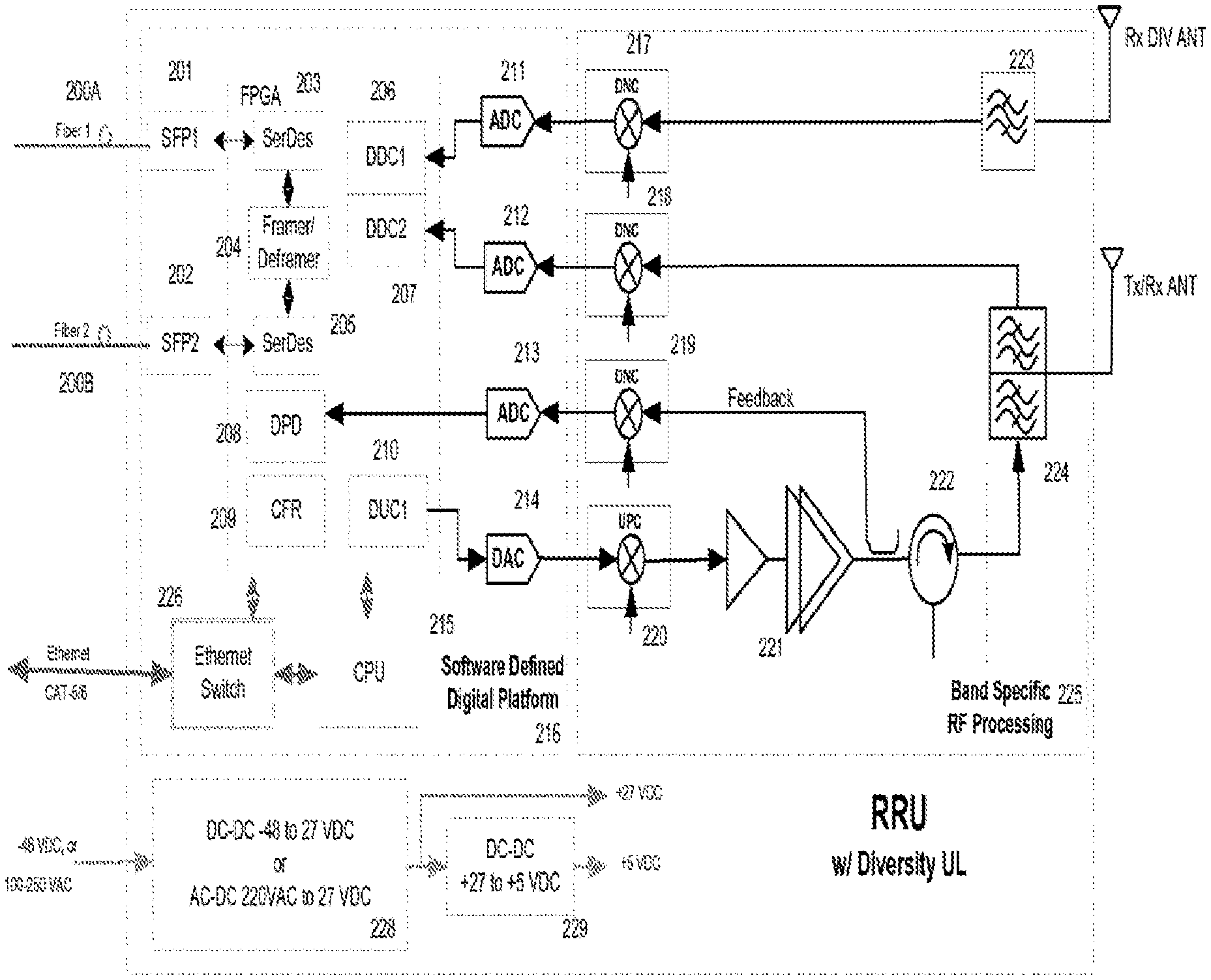
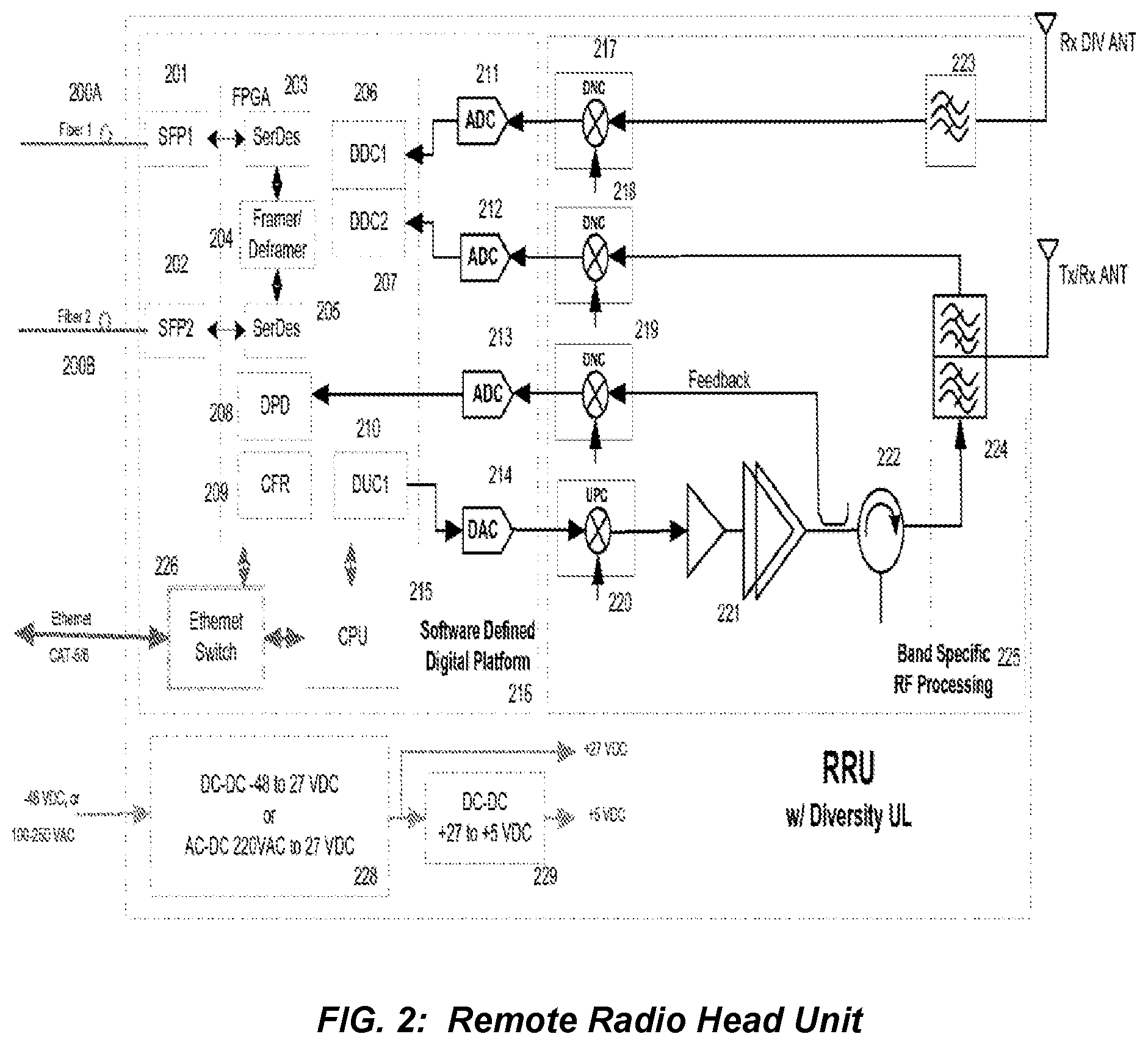
FIG. 2 is a block diagram showing a multi-channel High Power Remote Radio Head Unit according to one embodiment of the present invention.
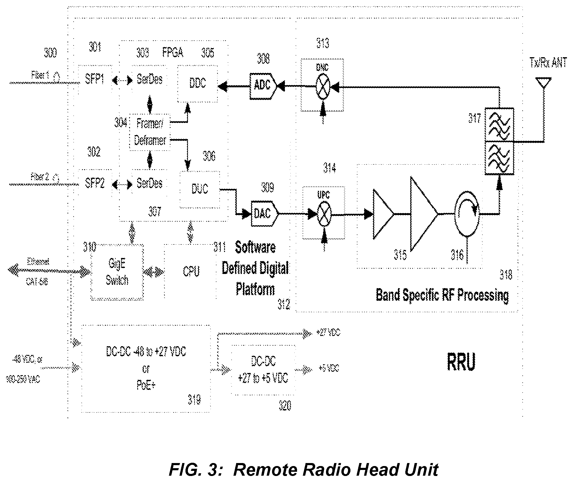
FIG. 3 is a block diagram multi-channel High Power Remote Radio Head Unit according to one embodiment of the present invention.
FIG. 4 is a block diagram of a Remote Radio Head Unit high level system of the present invention.
FIG. 5 is a block diagram of the Remote Radio Head Unit Access Module of the present invention.
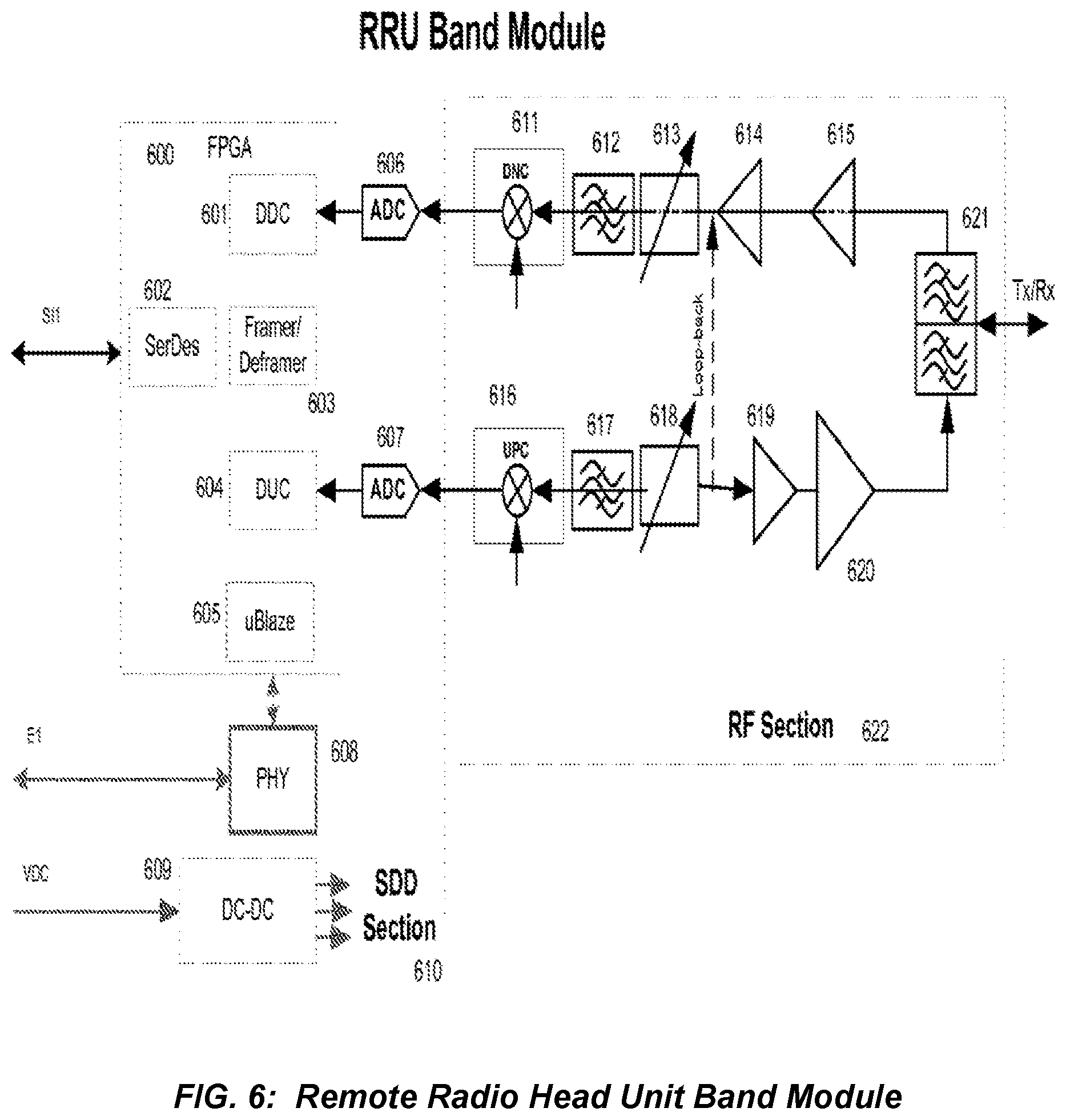
FIG. 6 is a Remote Radio Head Unit Band Module according to one embodiment of the present invention.
DETAILED DESCRIPTION OF THE PREFERRED EMBODIMENTS
The present invention is a novel Distributed Antenna System that utilizes a high speed Remote Radio Head Unit Access Module interconnected with Remote Radio Head Unit Band Module.
An embodiment of a Remote Radio Head Unit in accordance with the invention is shown in FIG. 2. Fiber 1, indicated at 200A, is a high speed fiber cable that transports data between the BTS and the Remote Radio Head Unit. Fiber 2, indicated at 200B, is used to daisy chain other remote radio head units which are thereby interconnected to the BTS or DAU. The software-defined digital platform 216 performs baseband signal processing, typically in an FPGA or equivalent. Building block 203 is a Serializer/Deserializer. The deserializer portion extracts the serial input bit stream from the optical fiber 201 and converts it into a parallel bit stream. The serializer portion performs the inverse operation for sending data from the Remote Radio Head Unit to the BTS. In an embodiment, the two distinct bit streams communicate with the BTS using different optical wavelengths over one fiber, although multiple fibers can be used in alternative arrangements. The deframer 204 deciphers the structure of the incoming bit stream and sends the deframed data to the Crest Factor Reduction Algorithm 209. The Crest Factor Reduction block 209 reduces the Peak-to-Average Ratio of the incoming signal so as to improve the Power amplifier DC-to-RF conversion efficiency. The waveform is then presented to the Digital Predistorter block 208. The digital predistorter compensates for the nonlinearities of the Power Amplifier 221 in an adaptive feedback loop. Digital Upconverter 210 filters and digitally translates the deframed signal to an IF frequency. The Framer 204 takes the data from the two digital downconverters 206, 207 and packs it into a Frame for transmission to the BTS over the optical fiber 201. Elements 211 and 212 are Analog to Digital converters that are used to translate the two analog receive signals into digital signals. The receiver comprises a diversity branch which contains a downconverter 217 and a Band Pass Filter 223. The main branch has a receiver path comprised of a duplexer 224 and a downconverter 218. In some embodiments, one or both downconverters 217 and 218 can have an integral uplink low-noise amplifier.
The power amplifier has an output coupler for extracting a replica of the output signal in the feedback path. The feedback signal is frequency-translated by downconverter 219 to either an IF frequency or baseband and presented to an Analog to Digital converter 213. This feedback signal is used in an adaptive loop for performing Digital Predistortion to compensate for any nonlinearities created by the power amplifier.
The Ethernet cable is used to locally communicate with the Remote Radio Head Unit. Switch 226 is used to allow easy access to either the FPGA or the CPU. DC power converters 228 and 229 are used to obtain the desired DC voltages for the Remote Radio Head Unit. Either an external voltage can be connected directly into the RRU or the DC power may be supplied through the Ethernet cable.
Although the description of the instant embodiment is directed to an application where a second optical fiber connection provides a capability for daisy chaining to other Remote Radio Head Units, an alternative embodiment provides multiple optical fiber connections to support a modified "hybrid star" configuration for appropriate applications which dictate this particular optical transport network configuration.
FIG. 3 depicts a remote radio head unit. In at least some designs, this architecture offers benefits when the RF output power is relatively low. In the embodiment shown in FIG. 3, digital predistortion and crest factor reduction are not employed as was the case in FIG. 2. Even though this topology shows a non-diversity configuration, a diversity receive branch can be added along with an additional transmitter path for development of a Multiple Input Multiple Output (MIMO) Remote Radio Head Unit.
The Remote Radio Head Unit high level system is shown in FIG. 4. It comprises a Remote Radio Head Unit Access Module 400 which communicates directly with the BTS or DAU. The function of the Remote Radio Head Unit Access Module 400 is to route the high speed data (at any desired speed, e.g., such as 10 Gbps as illustrated in FIG. 4) (the "Data Speed) to the multiple Remote Radio Head Unit Band Modules and allows for local communications with them via Ethernet. A backplane 401 is used to interconnect the Remote Radio Head Unit Access Module 400 with the various Remote Radio Head Unit Band Modules 402,403,404,405 at any speed lower than the Data Speed (e.g., less than or equal to 3 Gbps as illustrated in FIG. 4). The output ports of the Remote Radio Head Unit Band Modules are combined and sent to an antenna for transmission. An alternative embodiment is described as follows. Although the description of instant embodiment is directed to applications for up to four Remote Radio Head Unit Band Modules, an alternative embodiment involves feeding a much larger quantity of Remote Radio Head Unit Band Modules with signals of various bandwidths at various frequency bands covering multiple octaves of frequency range, to support a wide range of applications including location-based services, mobile internet, public safety communications, private enterprise telecommunications and broadband, and other wireless applications. The system can in theory support an infinite quantity of RRUs. Also, the Remote Radio Head Unit Band Modules may be set up remotely to have RF power values selected based on the specific desired applications as well as location-specific radio signal propagation factors. A further alternative embodiment leverages the flexibility of the architecture shown in FIG. 4 to provide a capability known as Flexible Simulcast. With Flexible Simulcast, the amount of radio resources (such as RF carriers, CDMA codes or TDMA time slots) assigned to a particular RRU or group of RRUs by each RRU Access Module can be set via software control to meet desired capacity and throughput objectives or wireless subscriber needs.
The detailed topology of the Remote Radio Head Unit Access Module is shown in FIG. 5. It comprises a Small form Factor Pluggable optic transceiver (SFP) 500 which operates on two distinct wavelengths, one for communicating from the BTS to the Remote Radio Head Unit Access Module and the other for communicating in the opposite direction. The SFP contains a Laser Diode for converting the electronic signal to an optical signal and an Optical detector for converting the optical signal into an electronic signal. A multiplexer/demultiplexer 501 converts the high speed data to multiple lower speed data paths for delivery to a FPGA 502. The multiplexer/demultiplexer 501 performs the opposite function when data is being sent back to the BTS or DAU. The framer/deframer 503 routes the data to the appropriate Remote Radio Head Unit Band Modules. An additional multiplexer/demultiplexer 506 allows for further expansion of lower speed Remote Radio Head Units. The number of Remote Radio Head units is only limited by the capability of the FPGA. Local communication with the Remote Radio Head Unit's Access Module's FPGA or the individual Remote Radio Head Unit Band Modules is via an Ethernet connection 508. Although the description of this embodiment is mainly directed to an application where a BTS or DAU (or multiple BTS or DAU) feeds the Remote Radio Head Unit Access Module, an alternative embodiment is described as follows. The alternative embodiment is one where the digital optical signals fed to the Remote Radio Head Unit Access Module may be generated by an RF-to-Digital interface which receives RF signals by means of one or more antennas directed to one or more base stations located at some distance from the Remote Radio Head Unit Access Module. A further alternative embodiment is one where the digital signals fed to the Remote Radio Head Unit Access Module may be generated in a combination of ways; some may be generated by an RF-to-Digital interface and some may be generated by a BTS or DAU. Some neutral host applications gain an advantage with regard to cost-effectiveness from employing this further alternative embodiment. Although the optical signals fed to the Remote Radio Head Unit Access Module described in the preferred and alternative embodiments are digital, the optical signals are not limited to digital, and can be analog or a combination of analog and digital. A further alternative embodiment employs transport on one or multiple optical wavelengths fed to the Remote Radio Head Unit Access Module.
The Remote Radio Head Unit Band Module is shown in FIG. 6. It comprises a Software Defined Digital (SDD) section 610 and an RF section 622. An alternative embodiment employs a Remote Antenna Unit comprising a broadband antenna with RRU Band Module Combiner and multiple plug-in module slots, into which multiple RRU Band Modules intended for operation in different frequency bands are inserted. To provide an overall compact unit with low visual impact, this embodiment employs RRU Band Modules which each have a physically small form factor. One example of a suitably small form factor for the RRU Band Module is the PCMCIA module format. A further alternative embodiment employs RRU Band Modules where each has an integral antenna, and the embodiment does not require a common antenna shared by multiple RRU Band Modules.
In summary, the Neutral Host Distributed Antenna System (NHDAS) of the present invention enables the use of remote radio heads for multi-operator multi-band configurations, which subsequently saves hardware resources and reduces costs. The NHDAS system is also reconfigurable and remotely field-programmable since the algorithms can be adjusted like software in the digital processor at any time.
Moreover, the NHDAS system is flexible with regard to being able to support various modulation schemes such as QPSK, QAM, OFDM, etc. in CDMA, TD-SCDMA, GSM, WCDMA, CDMA2000, LTE and wireless LAN systems. This means that the NHDAS system is capable of supporting multi-modulation schemes, multi-bands and multi-operators.
Although the present invention has been described with reference to the preferred embodiments, it will be understood that the invention is not limited to the details described thereof. Various substitutions and modifications have been suggested in the foregoing description, and others will occur to those of ordinary skill in the art. Therefore, all such substitutions and modifications are intended to be embraced within the scope of the invention as defined in the appended claims.
* * * * *
References
D00000
D00001
D00002
D00003
D00004
D00005
D00006
XML
uspto.report is an independent third-party trademark research tool that is not affiliated, endorsed, or sponsored by the United States Patent and Trademark Office (USPTO) or any other governmental organization. The information provided by uspto.report is based on publicly available data at the time of writing and is intended for informational purposes only.
While we strive to provide accurate and up-to-date information, we do not guarantee the accuracy, completeness, reliability, or suitability of the information displayed on this site. The use of this site is at your own risk. Any reliance you place on such information is therefore strictly at your own risk.
All official trademark data, including owner information, should be verified by visiting the official USPTO website at www.uspto.gov. This site is not intended to replace professional legal advice and should not be used as a substitute for consulting with a legal professional who is knowledgeable about trademark law.