Annular ring and non-pneumatic tire
Thompson May 25, 2
U.S. patent number 11,014,316 [Application Number 16/208,916] was granted by the patent office on 2021-05-25 for annular ring and non-pneumatic tire. This patent grant is currently assigned to Camso Inc.. The grantee listed for this patent is CAMSO INC.. Invention is credited to Ronald H. Thompson.


View All Diagrams
| United States Patent | 11,014,316 |
| Thompson | May 25, 2021 |
Annular ring and non-pneumatic tire
Abstract
The present invention provides an annular beam of monolithic construction of one homogeneous material and a related efficient, low-cost non-pneumatic tire. Specific geometric design, combined with nonlinear elastomer physical properties, enable the suppression of all reinforcing belts, continuous fibers, or other strengthening layers in the annular beam. The annular beam consists of at least two bands that are continuous in the circumferential direction and connected by a web geometry. The non-pneumatic tire consists of the annular beam, a ground contacting portion, a central wheel, and a plurality of web spokes that connect the wheel and beam. When the tire is loaded to a design load against a flat surface over a design contact length, a contact area of essentially uniform pressure is produced, while the load is transmitted from the beam to the hub via tension in the web spokes. The tire can be economically manufactured.
| Inventors: | Thompson; Ronald H. (Greenville, SC) | ||||||||||
|---|---|---|---|---|---|---|---|---|---|---|---|
| Applicant: |
|
||||||||||
| Assignee: | Camso Inc. (Magog,
CA) |
||||||||||
| Family ID: | 52018192 | ||||||||||
| Appl. No.: | 16/208,916 | ||||||||||
| Filed: | December 4, 2018 |
Prior Publication Data
| Document Identifier | Publication Date | |
|---|---|---|
| US 20190111645 A1 | Apr 18, 2019 | |
Related U.S. Patent Documents
| Application Number | Filing Date | Patent Number | Issue Date | ||
|---|---|---|---|---|---|
| 15677391 | Aug 15, 2017 | 10166732 | |||
| 14304217 | Sep 5, 2017 | 9751270 | |||
| 61835549 | Jun 15, 2013 | ||||
| Current U.S. Class: | 1/1 |
| Current CPC Class: | B60C 7/102 (20130101); B60C 7/18 (20130101); B29D 30/02 (20130101); B60C 7/12 (20130101); B60C 2007/005 (20130101); B29L 2030/006 (20130101) |
| Current International Class: | B29D 30/00 (20060101); B29D 30/02 (20060101); B60C 7/10 (20060101); B60C 7/12 (20060101); B60C 7/18 (20060101); B60C 7/00 (20060101) |
References Cited [Referenced By]
U.S. Patent Documents
| 2704102 | March 1955 | Starr et al. |
| 3494402 | February 1970 | Goldberger |
| 3804144 | April 1974 | Sand, Sr. |
| 3814158 | June 1974 | Ryder |
| 3827792 | August 1974 | Hollins |
| 3901300 | August 1975 | Toplis |
| 3907370 | September 1975 | Bard |
| 3957101 | May 1976 | Ippen et al. |
| 4164251 | August 1979 | Chung |
| 4169494 | October 1979 | Kubica et al. |
| 4201744 | May 1980 | Makinson |
| 4226273 | October 1980 | Long et al. |
| 4235270 | November 1980 | Kahaner et al. |
| 4244413 | January 1981 | Takahashi et al. |
| 4253893 | March 1981 | Clinefelter et al. |
| 4262724 | April 1981 | Sarkissian |
| 4273176 | June 1981 | Wyman et al. |
| 4281700 | August 1981 | Ross |
| 4287927 | September 1981 | Caravito et al. |
| 4310042 | January 1982 | Wyman et al. |
| 4345633 | August 1982 | Gilmore |
| 4350196 | September 1982 | Hampshire |
| 4387071 | June 1983 | Kirkhuff |
| 4446903 | May 1984 | Clinefelter et al. |
| 4471827 | September 1984 | Czapar |
| 4558727 | December 1985 | Golata et al. |
| 4580610 | April 1986 | Jackson |
| 4705087 | November 1987 | Markow |
| 4739810 | April 1988 | Markow |
| 4773461 | September 1988 | Landers et al. |
| 4784201 | November 1988 | Palinkas et al. |
| 4832098 | May 1989 | Palinkas et al. |
| 4867217 | September 1989 | Laurent |
| 4917162 | April 1990 | De Longcamp |
| 4921029 | May 1990 | Palinkas et al. |
| 4934425 | June 1990 | Gajewski |
| 4945962 | August 1990 | Pajtas |
| 4966212 | October 1990 | Hill |
| 5023040 | June 1991 | Gajewski et al. |
| 5024028 | June 1991 | Pierce et al. |
| 5042544 | August 1991 | Dehasse |
| 5050656 | September 1991 | Ho |
| 5086815 | February 1992 | Panaroni et al. |
| 5090464 | February 1992 | Kauzlarich et al. |
| 5139066 | August 1992 | Jarman |
| 5168910 | December 1992 | Zhang et al. |
| 5174634 | December 1992 | Blanck et al. |
| 5223599 | June 1993 | Gajewski |
| 5236027 | August 1993 | Lu |
| 5265659 | November 1993 | Pajtas et al. |
| 5313994 | May 1994 | Hill, III et al. |
| 5343916 | September 1994 | Duddey et al. |
| 5353853 | October 1994 | Hansson |
| 5460213 | October 1995 | Pajtas |
| 5494090 | February 1996 | Kejha |
| 5520232 | May 1996 | Fukutake et al. |
| 5676900 | October 1997 | Pajtas |
| 5743316 | April 1998 | Chrobak |
| 5879482 | March 1999 | Rooney et al. |
| 6068353 | May 2000 | Juncker et al. |
| 6167931 | January 2001 | Hsiao |
| 6170544 | January 2001 | Hottebart |
| 6279630 | August 2001 | Herbert |
| 6298891 | October 2001 | Harris |
| 6364424 | April 2002 | Lashlee et al. |
| 6431235 | August 2002 | Steinke |
| 6450222 | September 2002 | Fleming |
| 6530404 | March 2003 | Rooney |
| 6615885 | September 2003 | Ohm |
| 6617383 | September 2003 | Ikawa |
| 6640859 | November 2003 | Laurent et al. |
| 6640861 | November 2003 | Pereira et al. |
| 6681822 | January 2004 | Adams et al. |
| 6698480 | March 2004 | Cornellier |
| 6767495 | July 2004 | Aperce et al. |
| 6769465 | August 2004 | Rhyne et al. |
| 6769746 | August 2004 | Rodgers et al. |
| 6820942 | November 2004 | Knaak |
| 6983776 | January 2006 | Thompson et al. |
| 6994134 | February 2006 | Grah |
| 6994135 | February 2006 | Delfino et al. |
| 7013939 | March 2006 | Rhyne et al. |
| 7032634 | April 2006 | Laurent et al. |
| 7032637 | April 2006 | Meraldi |
| 7044180 | May 2006 | Rhyne et al. |
| 7066225 | June 2006 | Rhyne et al. |
| 7128794 | October 2006 | Veas |
| 7159632 | January 2007 | Fukui |
| 7201194 | April 2007 | Rhyne et al. |
| 7231948 | June 2007 | Forney, III et al. |
| 7281558 | October 2007 | Merino Lopez |
| 7329325 | February 2008 | Prost |
| 7418988 | September 2008 | Cron et al. |
| 7473472 | January 2009 | Chenaux et al. |
| 7506878 | March 2009 | Feick |
| 7546862 | June 2009 | Moon et al. |
| 7604029 | October 2009 | Myatt |
| 7650919 | January 2010 | Rhyne et al. |
| 7743806 | June 2010 | Abe |
| 7832263 | November 2010 | Rensel et al. |
| 7950428 | May 2011 | Hanada et al. |
| 7950429 | May 2011 | Re Fiorentin et al. |
| 8056593 | November 2011 | Palinkas et al. |
| 8061398 | November 2011 | Palinkas et al. |
| 8091596 | January 2012 | Louden |
| 8104524 | January 2012 | Manesh et al. |
| 8109308 | February 2012 | Manesh et al. |
| 8113253 | February 2012 | Arakawa et al. |
| 8141606 | March 2012 | Benzing, II et al. |
| 8166809 | May 2012 | Weston |
| 8176957 | May 2012 | Manesh et al. |
| 8215351 | July 2012 | Thompson |
| 8276628 | October 2012 | Hanada et al. |
| 8277590 | October 2012 | Delfino et al. |
| 8419408 | April 2013 | Wang |
| 8476808 | July 2013 | Weston et al. |
| 8491981 | July 2013 | Delfino et al. |
| 8517068 | August 2013 | Delfino et al. |
| 8544515 | October 2013 | Ma et al. |
| 8555941 | October 2013 | Perron et al. |
| 8567461 | October 2013 | Williams et al. |
| 8578607 | November 2013 | Kim |
| 8585947 | November 2013 | Meraldi et al. |
| 8609220 | December 2013 | Summers et al. |
| 8623169 | January 2014 | Delfino et al. |
| 8631844 | January 2014 | Anderfaas et al. |
| 8636490 | January 2014 | Martin et al. |
| 8646497 | February 2014 | Cron |
| 8651156 | February 2014 | Fadel et al. |
| 8662122 | March 2014 | Benzing, II |
| 8672006 | March 2014 | Moon |
| 8688421 | April 2014 | Summers et al. |
| 8714217 | May 2014 | Chon et al. |
| 8720504 | May 2014 | Benzing, II et al. |
| 8720505 | May 2014 | Fiorentin et al. |
| 8742265 | June 2014 | Weston et al. |
| 8746302 | June 2014 | Sachdev et al. |
| 8751270 | June 2014 | Hanson et al. |
| 8783310 | July 2014 | Abe |
| D711815 | August 2014 | Abe et al. |
| 8813797 | August 2014 | Anderson et al. |
| 8827383 | September 2014 | Simula |
| 8851131 | October 2014 | Luchini et al. |
| 8863798 | October 2014 | Re Fiorentin et al. |
| 8883283 | November 2014 | Delfino et al. |
| 8919404 | December 2014 | Schweitzer et al. |
| 8931531 | January 2015 | Kubeck et al. |
| 8944125 | February 2015 | Manesh et al. |
| 8950451 | February 2015 | Abe |
| 8960248 | February 2015 | Cron et al. |
| 8962120 | February 2015 | Delfino et al. |
| 8978723 | March 2015 | McCulley |
| 8991455 | March 2015 | Cron |
| 8999480 | April 2015 | Summers et al. |
| 9004127 | April 2015 | Manesh et al. |
| 9004901 | April 2015 | Wilson |
| 9016336 | April 2015 | Benzing, II et al. |
| 9027615 | May 2015 | Dermience et al. |
| D731958 | June 2015 | Kiwaki |
| 9090121 | July 2015 | Korus et al. |
| 9108470 | August 2015 | Tercha et al. |
| 9120351 | September 2015 | Mun et al. |
| 9139045 | September 2015 | Palinkas et al. |
| 9144946 | September 2015 | Creasap et al. |
| 9149994 | October 2015 | Martin et al. |
| 9156313 | October 2015 | Thompson |
| 9162407 | October 2015 | Martin et al. |
| 9180732 | November 2015 | Endicott |
| 9180737 | November 2015 | Amstutz et al. |
| 9186934 | November 2015 | Korus |
| 9205706 | December 2015 | Kline et al. |
| 9242509 | January 2016 | Chang |
| 9242510 | January 2016 | Korus |
| 9248697 | February 2016 | Iwamura |
| 9254716 | February 2016 | Cron et al. |
| 9266388 | February 2016 | Schaedler et al. |
| 9266506 | February 2016 | Korus et al. |
| 9272576 | March 2016 | Dotson et al. |
| 9278494 | March 2016 | Anderson et al. |
| 9283806 | March 2016 | Korus et al. |
| 9283810 | March 2016 | Korus et al. |
| 9283811 | March 2016 | Kim |
| 9290045 | March 2016 | Cron et al. |
| 9290053 | March 2016 | Choi et al. |
| 9290054 | March 2016 | Pfrenger et al. |
| 9290059 | March 2016 | Fredenburg et al. |
| 9302539 | April 2016 | Korus et al. |
| 9321312 | April 2016 | Asper |
| 9333799 | May 2016 | Choi et al. |
| 9346317 | May 2016 | Dotson et al. |
| 9346499 | May 2016 | Rudakevych et al. |
| 9352617 | May 2016 | Zhang |
| 9358704 | June 2016 | Kagota et al. |
| 9381773 | July 2016 | Seljan |
| 9387637 | July 2016 | Martin et al. |
| 9387726 | July 2016 | Choi et al. |
| 9393835 | July 2016 | Dotson et al. |
| D763785 | August 2016 | Abe et al. |
| 9421820 | August 2016 | Wilson et al. |
| 9440404 | September 2016 | Martin |
| 9440494 | September 2016 | Asper |
| 9463603 | October 2016 | Chadwick et al. |
| 9463668 | October 2016 | Fredenburg et al. |
| 9475244 | October 2016 | Williams et al. |
| 9475379 | October 2016 | Imamiya et al. |
| 9481208 | November 2016 | Matsuda et al. |
| 9487046 | November 2016 | Amstutz et al. |
| 9487052 | November 2016 | Asper |
| 9487892 | November 2016 | Abad |
| 9493045 | November 2016 | Cron et al. |
| 9511625 | December 2016 | Nishida et al. |
| 9511631 | December 2016 | Fudemoto et al. |
| 9511632 | December 2016 | Fudemoto et al. |
| 9550393 | January 2017 | Abe et al. |
| 9573422 | February 2017 | Gass et al. |
| 9573622 | February 2017 | Fujita et al. |
| 9604497 | March 2017 | Korus et al. |
| 9616703 | April 2017 | Nishida et al. |
| 9616713 | April 2017 | Lettieri et al. |
| 9623702 | April 2017 | Fudemoto et al. |
| 9643453 | May 2017 | Dotson et al. |
| 9662936 | May 2017 | Slanker et al. |
| 9662939 | May 2017 | Manesh et al. |
| 9713940 | July 2017 | Nishida et al. |
| 9718306 | August 2017 | Korus et al. |
| 9731556 | August 2017 | Martin et al. |
| 9751270 | September 2017 | Thompson |
| 9758002 | September 2017 | Carter et al. |
| 9776454 | October 2017 | Chen |
| 9821601 | November 2017 | Korus et al. |
| 9834040 | December 2017 | Benzing, II et al. |
| 9939835 | April 2018 | Watanabe |
| 2003/0201043 | October 2003 | Adams et al. |
| 2004/0007300 | January 2004 | Foucher |
| 2004/0112491 | June 2004 | Grah |
| 2006/0005903 | January 2006 | Fry et al. |
| 2006/0040077 | February 2006 | Wilson et al. |
| 2006/0060280 | March 2006 | Ladouce et al. |
| 2006/0102264 | May 2006 | Nicolas |
| 2006/0113016 | June 2006 | Cron et al. |
| 2006/0169797 | August 2006 | Kaltenheuser |
| 2006/0201597 | September 2006 | Lacour |
| 2006/0249235 | November 2006 | Lacour |
| 2007/0119531 | May 2007 | Steinke et al. |
| 2007/0200265 | August 2007 | Forney et al. |
| 2007/0267116 | November 2007 | Rhyne et al. |
| 2008/0029215 | February 2008 | Delfino et al. |
| 2008/0257463 | October 2008 | Re Fiorentin et al. |
| 2009/0107596 | April 2009 | Palinkas |
| 2009/0183810 | July 2009 | Vannan et al. |
| 2009/0211677 | August 2009 | Palinkas et al. |
| 2009/0211681 | August 2009 | Palinkas et al. |
| 2009/0250149 | October 2009 | Sebe |
| 2009/0294000 | December 2009 | Cron |
| 2009/0301625 | December 2009 | Moon et al. |
| 2010/0071819 | March 2010 | McCulley |
| 2010/0078111 | April 2010 | Anderson et al. |
| 2010/0132858 | June 2010 | Arakawa et al. |
| 2010/0132865 | June 2010 | Iwase et al. |
| 2010/0154948 | June 2010 | Dahlberg et al. |
| 2010/0193097 | August 2010 | McNier et al. |
| 2010/0200131 | August 2010 | Iwase et al. |
| 2011/0017377 | January 2011 | Albert et al. |
| 2011/0079336 | April 2011 | Thenault et al. |
| 2011/0104428 | May 2011 | Delfino |
| 2011/0146872 | June 2011 | Tercha |
| 2011/0180194 | July 2011 | Anderson et al. |
| 2011/0240193 | October 2011 | Matsuda et al. |
| 2011/0253281 | October 2011 | Christenbury |
| 2011/0260525 | October 2011 | Delfino et al. |
| 2011/0265926 | November 2011 | De Staercke |
| 2011/0278911 | November 2011 | Funaki |
| 2012/0038206 | February 2012 | Chadwick |
| 2012/0038207 | February 2012 | Williams |
| 2012/0193004 | August 2012 | Anderson et al. |
| 2012/0216932 | August 2012 | Cron et al. |
| 2012/0234444 | September 2012 | Palinkas et al. |
| 2012/0234445 | September 2012 | Manesh et al. |
| 2012/0241531 | September 2012 | Werner |
| 2012/0247635 | October 2012 | Manesh et al. |
| 2012/0318421 | December 2012 | Matsuda et al. |
| 2013/0048171 | February 2013 | Sandstrom et al. |
| 2013/0048174 | February 2013 | Cron |
| 2013/0150516 | June 2013 | Lettow |
| 2013/0167990 | July 2013 | Bae |
| 2013/0233458 | September 2013 | Meraldi et al. |
| 2013/0240097 | September 2013 | Cron et al. |
| 2013/0248067 | September 2013 | Delfino et al. |
| 2013/0276968 | October 2013 | Moore |
| 2013/0278045 | October 2013 | Dotson |
| 2013/0340902 | December 2013 | Kemeny |
| 2014/0062168 | March 2014 | Martin et al. |
| 2014/0062169 | March 2014 | Martin et al. |
| 2014/0062170 | March 2014 | Martin et al. |
| 2014/0062171 | March 2014 | Martin et al. |
| 2014/0062172 | March 2014 | Martin et al. |
| 2014/0070460 | March 2014 | Martin et al. |
| 2014/0083581 | March 2014 | Schaedler et al. |
| 2014/0110028 | April 2014 | Benzing, II |
| 2014/0159280 | June 2014 | Martin |
| 2014/0191564 | July 2014 | Gebeau |
| 2014/0191565 | July 2014 | Gebeau |
| 2014/0205836 | July 2014 | Hidrot et al. |
| 2014/0238561 | August 2014 | Choi et al. |
| 2014/0246135 | September 2014 | Andrews |
| 2014/0251518 | September 2014 | Abe et al. |
| 2014/0326374 | November 2014 | Cron et al. |
| 2014/0367007 | December 2014 | Thompson |
| 2015/0007926 | January 2015 | Sandstrom et al. |
| 2015/0013871 | January 2015 | McEwen et al. |
| 2015/0034222 | February 2015 | Martin et al. |
| 2015/0034225 | February 2015 | Martin |
| 2015/0048547 | February 2015 | Benzing, II |
| 2015/0083296 | March 2015 | Asper |
| 2015/0096654 | April 2015 | Sandstrom et al. |
| 2015/0158337 | June 2015 | Korus et al. |
| 2015/0174953 | June 2015 | Cron et al. |
| 2015/0191157 | July 2015 | Korus et al. |
| 2015/0210025 | July 2015 | Martin |
| 2015/0246577 | September 2015 | Fudemoto et al. |
| 2015/0251493 | September 2015 | Ma |
| 2015/0273945 | October 2015 | Fudemoto et al. |
| 2015/0273946 | October 2015 | Abe et al. |
| 2015/0283852 | October 2015 | Chen et al. |
| 2015/0283856 | October 2015 | Pfrenger et al. |
| 2015/0343840 | December 2015 | Kinney et al. |
| 2015/0343845 | December 2015 | Kinney et al. |
| 2016/0016426 | January 2016 | Endicott |
| 2016/0046091 | February 2016 | Kinney et al. |
| 2016/0046092 | February 2016 | Kinney et al. |
| 2016/0046153 | February 2016 | Yoo |
| 2016/0046154 | February 2016 | Kim |
| 2016/0096400 | April 2016 | Nomura et al. |
| 2016/0107402 | April 2016 | Cron et al. |
| 2016/0121656 | May 2016 | Sugiya et al. |
| 2016/0128266 | May 2016 | Phely et al. |
| 2016/0152078 | June 2016 | Korus et al. |
| 2016/0159150 | June 2016 | Pfrenger et al. |
| 2016/0159152 | June 2016 | Delfino et al. |
| 2016/0193876 | July 2016 | Kyo et al. |
| 2016/0193877 | July 2016 | Jang et al. |
| 2016/0200144 | July 2016 | Iwamura et al. |
| 2016/0214435 | July 2016 | Schaedler et al. |
| 2016/0221284 | August 2016 | Andrews et al. |
| 2016/0236514 | August 2016 | Abe |
| 2016/0250893 | September 2016 | Shoji et al. |
| 2016/0257170 | September 2016 | Sugiya et al. |
| 2016/0272006 | September 2016 | Abe |
| 2016/0280005 | September 2016 | Cron et al. |
| 2016/0288569 | October 2016 | Parfondry et al. |
| 2016/0297244 | October 2016 | Abe |
| 2016/0303812 | October 2016 | Lepretre et al. |
| 2016/0311479 | October 2016 | Rudakevych et al. |
| 2016/0312014 | October 2016 | Lemerle et al. |
| 2016/0318342 | November 2016 | Delfino |
| 2016/0319111 | November 2016 | Chouvel et al. |
| 2016/0347119 | December 2016 | Quiroz |
| 2017/0001470 | January 2017 | Merino Lopez |
| 2017/0008338 | January 2017 | Merino Lopez |
| 2017/0008341 | January 2017 | Martin |
| 2017/0008342 | January 2017 | Martin et al. |
| 2017/0015134 | January 2017 | Ma |
| 2017/0015141 | January 2017 | Shoji et al. |
| 2017/0057288 | March 2017 | Sugiya et al. |
| 2017/0057289 | March 2017 | Pratt |
| 2017/0057294 | March 2017 | Iwamura et al. |
| 2017/0072746 | March 2017 | Iwamura et al. |
| 2017/0080756 | March 2017 | Van Riper et al. |
| 2017/0087930 | March 2017 | McMaster et al. |
| 2017/0087931 | March 2017 | Gaylo et al. |
| 2017/0087937 | March 2017 | Korus et al. |
| 2017/0096032 | April 2017 | Iwamura et al. |
| 2017/0106699 | April 2017 | Iwamura et al. |
| 2017/0113484 | April 2017 | Iwamura et al. |
| 2017/0113488 | April 2017 | Iwamura et al. |
| 2017/0113490 | April 2017 | Iwamura et al. |
| 2017/0113491 | April 2017 | Iwamura et al. |
| 2017/0120671 | May 2017 | Miles et al. |
| 2017/0120680 | May 2017 | Takahashi et al. |
| 2017/0120681 | May 2017 | Toyosawa |
| 2017/0129285 | May 2017 | Toyosawa |
| 2017/0136814 | May 2017 | Abe et al. |
| 2017/0157983 | June 2017 | Siegel |
| 2017/0157984 | June 2017 | Van Riper et al. |
| 2017/0166002 | June 2017 | Benzing, II et al. |
| 2017/0174002 | June 2017 | Downing |
| 2017/0174003 | June 2017 | Benzing, II et al. |
| 2017/0174004 | June 2017 | Benzing, II |
| 2017/0174005 | June 2017 | Van Riper et al. |
| 2017/0197467 | July 2017 | Iwamura et al. |
| 2017/0232787 | August 2017 | Hasegawa et al. |
| 2017/0239994 | August 2017 | Raulerson, Jr. et al. |
| 2017/0253084 | September 2017 | Takahashi et al. |
| 2017/0267028 | September 2017 | Pfrenger et al. |
| 2017/0291453 | October 2017 | Sugiya et al. |
| 2017/0297370 | October 2017 | Korus et al. |
| 2017/0297371 | October 2017 | Sportelli |
| 2017/0297372 | October 2017 | Talbot et al. |
| 2017/0297373 | October 2017 | Sportelli et al. |
| 2017/0297374 | October 2017 | Sportelli |
| 2017/0305192 | October 2017 | Yokoyama et al. |
| 2017/0305195 | October 2017 | Takahashi et al. |
| 2017/0326915 | November 2017 | Son et al. |
| 2017/0334245 | November 2017 | Laskowitz |
| 3008828 | Jun 2017 | CA | |||
| 3008846 | Jun 2017 | CA | |||
| 0 353 006 | Jan 1990 | EP | |||
| 0 502 353 | Sep 1992 | EP | |||
| 3923073 | May 2007 | JP | |||
| 2011-219009 | Nov 2011 | JP | |||
| 2 002 956 | Dec 2010 | NL | |||
| 96/05917 | Feb 1996 | WO | |||
| 2000/018592 | Apr 2000 | WO | |||
| 2000/037269 | Jun 2000 | WO | |||
| 2006/022788 | Mar 2006 | WO | |||
| 2008/045098 | Apr 2008 | WO | |||
| 2008/118983 | Oct 2008 | WO | |||
| 2009/005945 | Jan 2009 | WO | |||
| 2009/005946 | Jan 2009 | WO | |||
| 2009/042460 | Apr 2009 | WO | |||
| 2009/0135561 | Nov 2009 | WO | |||
| 2010/138150 | Dec 2010 | WO | |||
| 2011/011419 | Jan 2011 | WO | |||
| 2013/095499 | Jun 2013 | WO | |||
| 2014/036415 | Mar 2014 | WO | |||
| 2014/039814 | Mar 2014 | WO | |||
| 2014/093135 | Jun 2014 | WO | |||
| 2014/172095 | Oct 2014 | WO | |||
| 2015/013036 | Jan 2015 | WO | |||
| 2015/017100 | Feb 2015 | WO | |||
| 2015/017133 | Feb 2015 | WO | |||
| 2015/023969 | Feb 2015 | WO | |||
| 2015/052987 | Apr 2015 | WO | |||
| 2015/072222 | May 2015 | WO | |||
| 2015/100080 | Jul 2015 | WO | |||
| 2015/112417 | Jul 2015 | WO | |||
| 2015/112720 | Jul 2015 | WO | |||
| 2015/141579 | Sep 2015 | WO | |||
| 2015/165777 | Nov 2015 | WO | |||
| 2015/175002 | Nov 2015 | WO | |||
| 2015/175003 | Nov 2015 | WO | |||
| 2015/187394 | Dec 2015 | WO | |||
| 2015/194087 | Dec 2015 | WO | |||
| 2015/194088 | Dec 2015 | WO | |||
| 2015/194277 | Dec 2015 | WO | |||
| 2015/198387 | Dec 2015 | WO | |||
| 2015/198637 | Dec 2015 | WO | |||
| 2016/021300 | Feb 2016 | WO | |||
| 2016/056444 | Apr 2016 | WO | |||
| 2016/072181 | May 2016 | WO | |||
| 2016/084512 | Jun 2016 | WO | |||
| 2016/089480 | Jun 2016 | WO | |||
| 2016/098477 | Jun 2016 | WO | |||
| 2016/100004 | Jun 2016 | WO | |||
| 2016/100005 | Jun 2016 | WO | |||
| 2016/100006 | Jun 2016 | WO | |||
| 2016/105654 | Jun 2016 | WO | |||
| 2016/109557 | Jul 2016 | WO | |||
| 2016/109648 | Jul 2016 | WO | |||
| 2016/109702 | Jul 2016 | WO | |||
| 2016/114167 | Jul 2016 | WO | |||
| 2016/114168 | Jul 2016 | WO | |||
| 2016/116457 | Jul 2016 | WO | |||
| 2016/123180 | Aug 2016 | WO | |||
| 2016/148295 | Sep 2016 | WO | |||
| 2016/152887 | Sep 2016 | WO | |||
| 2016/189126 | Dec 2016 | WO | |||
| 2016/189209 | Dec 2016 | WO | |||
| 2016/203098 | Dec 2016 | WO | |||
| 2017/024366 | Feb 2017 | WO | |||
| 2017/035630 | Mar 2017 | WO | |||
| 2017/039451 | Mar 2017 | WO | |||
| 2017/039604 | Mar 2017 | WO | |||
| 2017/040390 | Mar 2017 | WO | |||
| 2017/052010 | Mar 2017 | WO | |||
| 2017/061405 | Apr 2017 | WO | |||
| 2017/067869 | Apr 2017 | WO | |||
| 2017/072560 | May 2017 | WO | |||
| 2017/072562 | May 2017 | WO | |||
| 2017/086993 | May 2017 | WO | |||
| 2017/087853 | May 2017 | WO | |||
| 2017/110769 | Jun 2017 | WO | |||
| 2017/111944 | Jun 2017 | WO | |||
| 2017/112130 | Jun 2017 | WO | |||
| 2017/116384 | Jul 2017 | WO | |||
| 2017/116385 | Jul 2017 | WO | |||
| 2017/116386 | Jul 2017 | WO | |||
| 2017/116389 | Jul 2017 | WO | |||
| 2017/116390 | Jul 2017 | WO | |||
| 2017/116454 | Jul 2017 | WO | |||
| 2017/116463 | Jul 2017 | WO | |||
| 2017/116472 | Jul 2017 | WO | |||
| 2017/116475 | Jul 2017 | WO | |||
| 2017/116478 | Jul 2017 | WO | |||
| 2017/116481 | Jul 2017 | WO | |||
| 2017/116556 | Jul 2017 | WO | |||
| 2017/116557 | Jul 2017 | WO | |||
| 2017/116561 | Jul 2017 | WO | |||
| 2017/116565 | Jul 2017 | WO | |||
| 2017/116804 | Jul 2017 | WO | |||
| 2017/117365 | Jul 2017 | WO | |||
| 2017/117368 | Jul 2017 | WO | |||
| 2017/117587 | Jul 2017 | WO | |||
| 2017/117598 | Jul 2017 | WO | |||
| 2017/117599 | Jul 2017 | WO | |||
| 2017/117605 | Jul 2017 | WO | |||
| 2017/117606 | Jul 2017 | WO | |||
| 2017/131742 | Aug 2017 | WO | |||
| 2017/159899 | Sep 2017 | WO | |||
| 2017/200645 | Nov 2017 | WO | |||
Other References
|
Nov. 3, 2014 Search Report issued in International Application No. PCT/US2014/042327. cited by applicant . Nov. 3, 2014 Written Opinion issued in International Application No. PCT/US2014/042327. cited by applicant . Dec. 15, 2015 U.S. Office Action Issued in U.S. Appl. No. 14/304,217. cited by applicant . Dec. 23, 2015 International Preliminary Report on Patentability issued in International Patent Application No. PCT/US2014/042327. cited by applicant . Muvdi, B.B. et al.; "Shear and Bending Moment in Beams;" Engineering Mechanics of Materials; Macmillan Publishing Co., Inc.; Jun. 1980; New York, NY; pp. 23-31. cited by applicant . Muvdi, B.B. et al.; "Deflections of Beams;" Engineering Mechanics of Materials; Macmillan Publishing Co., Inc.; Jun. 1980; New York, NY; pp. 266-333. cited by applicant . May 19, 2016 U.S. Office Action Issued in U.S. Appl. No. 14/304,217. cited by applicant . Apr. 13, 2016 Search Report issued in International Patent Application No. PCT/US2016/016630. cited by applicant . Apr. 13, 2016 Written Opinion issued in International Patent Application No. PCT/US2016/016630. cited by applicant . Feb. 1, 2017 Supplementary European Search Report issued in European Patent Application No. 14811289.9. cited by applicant . Mar. 27, 2018 Office Action issued in U.S. Appl. No. 15/677,391. cited by applicant . Rhyne, T. B. and Cron, S. M., "Development of a Non-Pneumatic Wheel," Tire Science and Technology, TSTCA, vol. 34, No. 3, Jul.-Sep. 2006, pp. 150-169. cited by applicant . Oct. 30, 2017 Search Report issued in International Patent Application No. PCT/2017/035008 dated Oct. 30, 2017 Search Report. cited by applicant . Oct. 30, 2017 Written Opinion issued in International Patent Application No. PCT/2017/035008. cited by applicant . May 19, 2016 Office Action issued in U.S. Appl. No. 14/304,217. cited by applicant . Nov. 3, 2016 Notice of Allowance issued in U.S. Appl. No. 14/304,217. cited by applicant . Mar. 2, 2017 International Preliminary Report on Patentability issued in International Patent Application No. PCT/US2016/016630. cited by applicant . Aug. 16, 2018 Extended Search Report issued in European Patent Application No. 16747290.1. cited by applicant . Feb. 19, 2018 International Search Report issued in International Patent Application No. PCT/CA2017/051577. cited by applicant . Feb. 19, 2018 Written Opinion issued in International Patent Application No. PCT/CA2017/051577. cited by applicant . Nov. 13, 2018 Examiner's Report issued in European Patent Application No. 14811289.9. cited by applicant . Taheri; Center for Tire Research (CenTiRe); presentation at Virginia Tech; Nov. 8, 2017. cited by applicant . Jaehyung Ju et al.; "Rolling Resistance of a Nonpneumatic Tire Having a Porous Elastomer Composite Shear Band"; Tire Science and Technology; 41(3) (Jul. 2013); pp. 154-173. cited by applicant. |
Primary Examiner: Phan; Hau V
Parent Case Text
PRIORITY CLAIM
This is a Continuation of application Ser. No. 15/677,391 filed Aug. 15, 2017, which is a Continuation of U.S. patent application Ser. No. 14/304,217 filed Jun. 13, 2014, which claims the benefit of the benefit of U.S. Provisional Patent No. 61/835,549 filed Jun. 15, 2013. The disclosure of the prior applications is hereby incorporated by reference herein in their entirety. Furthermore, where a definition or use of a term in a reference, which is incorporated by reference herein, is inconsistent or contrary to the definition of that term provided herein, the definition of that term provided herein applies and the definition of that term in the reference does not apply.
Claims
What is claimed is:
1. A non-pneumatic tire comprising: an annular beam configured to deflect at a contact patch of the non-pneumatic tire with a ground surface, the annular beam comprising: an outer annular portion; an inner annular portion; and a shearing annular portion between the outer annular portion and the inner annular portion of the annular beam, the outer annular portion, the inner annular portion, and the shearing annular portion of the annular beam being elastomeric, the annular beam being configured to deflect more by shearing than by bending at the contact patch of the non-pneumatic tire; a hub spaced radially from the annular beam; and a plurality of spokes that extend from the annular beam to the hub such that, when the non-pneumatic tire is loaded, upper ones of the spokes above an axis of rotation of the non-pneumatic tire are in tension; wherein the non-pneumatic tire comprises thermoplastic elastomeric material forming at least part of the spokes and having a flex fatigue limit of at least 4 MPa according to ASTM D671.
2. The non-pneumatic tire of claim 1, wherein each of the spokes extends from the annular beam to the hub without being intersected at more than one point.
3. The non-pneumatic tire of claim 2, wherein each of the spokes extends from the annular beam to the hub without being intersected.
4. The non-pneumatic tire of claim 1, wherein each of the spokes extends from the annular beam to the hub without being connected to other ones of the spokes at more than one point between the annular beam and the hub.
5. The non-pneumatic tire of claim 4, wherein the flex fatigue limit of the thermoplastic elastomeric material is at least 7 MPa.
6. The non-pneumatic tire of claim 4, wherein a Young's modulus of the thermoplastic elastomeric material is at least 90 MPa.
7. The non-pneumatic tire of claim 4, wherein the thermoplastic elastomeric material is a thermoplastic co-polymer.
8. The non-pneumatic tire of claim 4, wherein the spokes are entirely formed of the thermoplastic elastomeric material.
9. The non-pneumatic tire of claim 4, wherein: at least one of the outer annular portion and the inner annular portion of the annular beam is free of substantially inextensible reinforcement running in a circumferential direction of the annular beam.
10. The non-pneumatic tire of claim 9, wherein each of the outer annular portion and the inner annular portion of the annular beam is free of substantially inextensible reinforcement running in the circumferential direction of the annular beam.
11. The non-pneumatic tire of claim 4, wherein the annular beam is free of substantially inextensible reinforcement running in a circumferential direction of the annular beam.
12. The non-pneumatic tire of claim 4, wherein the annular beam comprises a plurality of voids distributed in a circumferential direction of the annular beam and arranged to cause the annular beam to deflect more by shearing than by bending at the contact patch of the non-pneumatic tire.
13. The non-pneumatic tire of claim 4, wherein each of the spokes extends from the annular beam to the hub without being connected to other ones of the spokes between the annular beam and the hub.
14. The non-pneumatic tire of claim 1, wherein each of the spokes is unconnected to other ones of the spokes from the annular beam to the hub.
15. The non-pneumatic tire of claim 1, wherein the thermoplastic elastomeric material forms at least part of the annular beam.
16. The non-pneumatic tire of claim 15, wherein the thermoplastic elastomeric material forms at least a majority of the annular beam.
17. The non-pneumatic tire of claim 1, wherein the annular beam and the spokes are entirely formed of the thermoplastic elastomeric material.
18. A non-pneumatic tire comprising: an annular beam configured to deflect at a contact patch of the non-pneumatic tire with a ground surface, the annular beam comprising: an outer annular portion; an inner annular portion; and a shearing annular portion between the outer annular portion and the inner annular portion of the annular beam, the outer annular portion, the inner annular portion, and the shearing annular portion of the annular beam being elastomeric, the annular beam being configured to deflect more by shearing than by bending at the contact patch of the non-pneumatic tire; a hub spaced radially from the annular beam; and a plurality of spokes that extend from the annular beam to the hub such that, when the non-pneumatic tire is loaded, upper ones of the spokes above an axis of rotation of the non-pneumatic tire are in tension; wherein: each of the spokes is not connected to adjacent ones of the spokes at more than one location between the annular beam and the hub; and the non-pneumatic tire comprises thermoplastic elastomeric material forming at least part of the spokes.
19. The non-pneumatic tire of claim 18, wherein the thermoplastic elastomeric material forms at least a majority of the annular beam.
20. The non-pneumatic tire of claim 19, wherein the thermoplastic elastomeric material forms an entirety of the annular beam.
21. The non-pneumatic tire of claim 18, wherein each of the spokes is unconnected to other ones of the spokes from the annular beam to the hub.
22. The non-pneumatic tire of claim 18, wherein the thermoplastic elastomeric material has a flex fatigue limit of at least 4 MPa according to ASTM D671.
23. The non-pneumatic tire of claim 18, wherein the thermoplastic elastomeric material has a flex fatigue limit of at least 7 MPa according to ASTM D671.
24. The non-pneumatic tire of claim 18, wherein the thermoplastic elastomeric material is a thermoplastic co-polymer.
25. The non-pneumatic tire of claim 18, wherein each of the spokes is unconnected to other ones of the spokes from the annular beam to the hub.
26. The non-pneumatic tire of claim 18, wherein the annular beam is free of substantially inextensible reinforcement running in a circumferential direction of the annular beam.
27. A process for manufacturing a non-pneumatic tire that comprises: an annular beam configured to deflect at a contact patch of the non-pneumatic tire with a ground surface, the annular beam comprising: an outer annular portion; an inner annular portion; and a shearing annular portion between the outer annular portion and the inner annular portion of the annular beam, the outer annular portion, the inner annular portion, and the shearing annular portion of the annular beam being elastomeric, the annular beam being configured to deflect more by shearing than by bending at the contact patch of the non-pneumatic tire; a hub spaced radially from the annular beam; and a plurality of spokes that extend from the annular beam to the hub such that, when the non-pneumatic tire is loaded, upper ones of the spokes above an axis of rotation of the non-pneumatic tire are in tension; the process comprising: forming the annular beam; and forming the spokes; wherein: each of the spokes is not connected to adjacent ones of the spokes at more than one location between the annular beam and the hub; and the non-pneumatic tire comprises thermoplastic elastomeric material forming at least part of the spokes.
28. The process of claim 27, wherein: each of the spokes is unconnected to other ones of the spokes from the annular beam to the hub.
29. The process of claim 27, wherein the thermoplastic elastomeric material has a flex fatigue limit of at least 4 MPa according to ASTM D671.
30. The process of claim 27, wherein the thermoplastic elastomeric material has a flex fatigue limit of at least 7 MPa according to ASTM D671.
31. The process of claim 27, wherein said forming the spokes comprises injection molding the spokes.
32. The process of claim 31, wherein said injection molding the spokes comprises joining the spokes to the annular beam.
Description
TECHNICAL FIELD OF THE INVENTION
The present invention is in the field of non-pneumatic tires and related technologies. The application scope includes low-cost, efficient designs for tires. In manufacturing, the field includes high-pressure thermoplastic injection, reaction injection, and cast molding. The material science field involves thermoplastic and thermoset elastomers having specific nonlinear mechanical properties.
BACKGROUND OF THE INVENTION
Pneumatic tires offer high load capacity per unit mass, along with a large contact area and relatively low vertical stiffness. High contact area results in the ability to both efficiently generate high tangential forces and obtain excellent wear characteristics. However, pneumatic tires are also prone to flats. Well known in the patent literature, non-pneumatic tires offer flat-free operation, yet generally contain some compromise.
Higher cost is often associated with non-pneumatic tires when complex assemblages of composite materials are used. Related to this, production methodologies can be laborious. For example, U.S. Pat. No. 7,201,194 discloses a non-pneumatic tire containing an annular band which is comprised of at least two inextensible membrane-like reinforcing layers, which are separated by an elastomeric layer. This annular band is then affixed to a central wheel via flexible spokes in a web design. This composite composition suggests a complex manufacturing process. High production costs could be involved.
Conversely, U.S. Pat. No. 6,615,885 discloses a non-pneumatic tire that can be fabricated without composite reinforcement. The design consists of a rim connected to a hub via curved spokes. The spokes are sufficiently rigid such that loads are transmitted via bending. Such a structure works acceptably well for very small tires and low loads; however, one skilled in the art of non-pneumatic structures can show that this technological approach would result in high tire mass for applications supporting higher loads in larger-scale applications.
U.S. Pat. No. 7,013,939 discloses a non-pneumatic tire consisting of a simple elastomeric band, a hub, and connecting spokes which act primarily in tension. As with U.S. Pat. No. 6,615,885, this solution works for very small tires and low loads. However, at higher loads with larger tire dimensions, one skilled in the art of non-pneumatic tire design can show that the contact area characteristics become strongly degraded. This would result in a loss of performance.
US Patent Application US2012/0234444 A1 discloses a non-pneumatic tire with an annular reinforcing web, made of a homogeneous material. However, the disclosed structure supports load via compression. The generally radial spokes are thick and designed to act as columns under normal operation. Thus, the distance between the outer tire diameter and the rigid wheel diameter must be relatively small, in order to resist buckling under high loads. Therefore, the absorbed energy potential--a principle virtue of the pneumatic tire--may be limited in this tire design.
Finally, U.S. Pat. No. 8,517,068 B2 discloses a resilient wheel that operates similarly to the invention of U.S. Pat. No. 7,201,194, except that the circumferential membranes are connected by discrete cylindrical support elements. Here, the advantages could include lower weight and the ability to overcome temperature limitations associated with elastomers. However, the assemblage of these disparate elements could be laborious and expensive.
The present invention breaks these compromises by disclosing a non-pneumatic tire that, in a preferred embodiment, can be constructed from a single homogeneous material, is light-weight, capable of large deflection, and obtains a large, constant pressure contact area. Structure geometries and non-linear material properties are disclosed that accomplish the same function as more complicated designs of prior art. In particular, prior art often employs reinforcements that behave like inextensible membranes, as well as sandwich composite constructions. Conversely, the present design is elastomeric, has no membrane-like behavior, and contains no reinforcement. While the invention has elegant simplicity, the principles of operation are not readily apparent to one of ordinary skill in the art of tire design.
While having potentially complex features, the geometries disclosed in the present invention are generally suitable for realization in the thermoplastic injection, cast, or reaction injection molding process. These practical attributes result in lower cost when produced in large volume, yet do not come at the expense of the aforementioned primary performance attributes of a pneumatic tire.
Second stage processes can be applied to this invention. For example, a non-pneumatic tire with a thermoplastic material can be designed, per procedures disclosed in this application. Then, a tread material and tread pattern can be affixed to a radially exterior extent of the annular beam. This can be accomplished via retreading procedures, by a 2.sup.nd stage injection process, or by co-injection.
SUMMARY OF THE INVENTION
A full and enabling disclosure of the present subject matter, including the best mode thereof, directed to one of ordinary skill in the art, is set forth in the specification, which makes reference to the appended figures.
FIG. 1 is an isometric view of an annular beam of the invention, along with the coordinate system defined by the invention.
FIG. 2 is an isometric view of a non-pneumatic tire of the invention.
FIG. 3 is an isometric view of an exemplary embodiment of a non-pneumatic tire of invention.
FIG. 4 is an isometric view of a second exemplary embodiment of a non-pneumatic tire of the invention.
FIG. 5 is an x-z plane equatorial cross-section view of an alternative arrangement of the web connecting two continuous bands in the annular beam.
FIG. 6 is an equatorial view of a third arrangement of the web connecting two continuous bands in the annular beam.
FIG. 7 is an equatorial view of a fourth arrangement of the web connecting two continuous bands in the annular beam.
FIG. 8 is an x-z plane equatorial view of a radial arrangement of the web spokes that connecting the annular beam to the central hub.
FIG. 9 is an equatorial view of a second arrangement of the web spokes.
FIG. 10 is an equatorial view of a third arrangement of the spokes.
FIG. 11 is an equatorial view of a fourth arrangement of the spokes.
FIG. 12 is an equatorial view of the annular beam, in contact with two parallel flat contact surfaces.
FIG. 13 is an equatorial view of the tire, in contact with a flat surface.
FIG. 14 is a Finite Element Model (FEM) of a straight beam with two continuous bands connected by webbing geometry subjected to simple shear.
FIG. 15 is a FEM of a simply supported straight beam with two continuous bands connected by webbing geometry subjected to a uniform distributed load.
FIG. 16 gives a simple example geometry definition of the beam used in the FEM models of FIG. 14 and FIG. 15.
FIG. 17 shows FEM results of models from FIG. 14 and FIG. 15, when using geometry definition given in FIG. 16.
FIG. 18 is a 2D FEM of a tire in accordance with the invention, subjected to a vertical load of 1100 N.
FIG. 19 is closer view of the contact region of the model from FIG. 18, showing contact patch force distribution and Von Mises stress.
FIG. 20 is a plot of tensile stress vs. tensile strain for a preferred homogeneous elastomeric material in accordance with the invention.
FIG. 21 is an isometric view of a third exemplary embodiment of a tire according to the invention.
FIG. 22 is an isometric view of a fourth exemplary embodiment of a non-pneumatic tire of the invention.
FIG. 23 is a process flow map of a design procedure for a tire in accordance with the invention.
DETAILED DESCRIPTION OF THE INVENTION
Reference will now be made in detail to embodiments of the invention, one or more examples of which are illustrated in the Figures. Each example is provided by way of explanation of the invention, and not meant as a limitation of the invention. For example, features illustrated or described as part of one embodiment can be used with another embodiment to yield still a third embodiment.
Definitions
The following terms are defined as follows for this disclosure, with material properties referring to those at ambient temperature, unless otherwise noted:
"Wheel" or "Hub" refers to any structure for supporting the tire and capable of attachment to a vehicle axis, and such terms are interchangeable herein.
"Modulus" means Young's tensile modulus of elasticity measured per ISO 527-1/-2. "Young's Modulus," "tensile modulus," and "modulus" are used interchangeably herein.
"Secant Modulus" is the tensile stress divided by the tensile strain for any given point on the tensile stress vs. tensile strain curve measured per ISO 527-1/-2.
"Shear Modulus" means the shear modulus of elasticity, calculated by Equation 10, below.
"Tensile Strain at Break" means the tensile strain corresponding to the point of rupture as measured by ISO 527-1/-2.
"Flex Fatigue" is the flexural stress fatigue limit, measured by ASTM D671.
"Design Load" of a tire is the usual and expected operating load of the tire.
"Design contact length" is the contact length over a substantially flat surface when loaded to design load.
The coordinate system defined by the invention is shown in FIG. 1: The circumferential direction is the X direction. The axial direction is the Y direction, coincident with the rotation axis 140. The radial direction is the Z direction.
The tire equatorial plane is the plane defined by the x-z axes.
DETAILED DESCRIPTION
A non-pneumatic tire employing an annular beam of homogeneous material is represented herein by structural two dimensional Finite Element Models (FEM). This section first provides an overall description of the invention; then, a preferred design practice for developing a tire having desired performance characteristics will be disclosed. This procedure employs FEM.
FIG. 1 shows an isometric view of an annular beam 100. The beam defines a radial direction (Z), a circumferential direction (X) and an axial direction (Y), which is coincident with the axis of rotation 140. The beam is of monolithic construction, composed of one homogeneous material. The beam consists of at least a first circumferentially continuous band 120, lying on a radially inward extent of a web structure 110. At least a second continuous band 130 lies on a radially outward extent of the web structure. In a preferred embodiment, the beam is constructed of an elastomer of specific non-linear mechanical material properties, and having a modulus of at least 90 MPa, and preferably between 150 to 350 MPa.
FIG. 2 shows an isometric view of the annular beam 100, embodied in a non-pneumatic tire 150. The annular beam is connected to a central hub 170 by a plurality of web spokes 180 that traverse the hub and beam in the axial direction. The spokes have a sheet-like geometry in this example, yet other embodiments will be disclosed. The tire is loaded by and revolves around axis 140. A ground contacting portion 160 lies on a radially outward extent of the annular beam.
FIG. 3 shows an isometric view of an exemplary embodiment of a non-pneumatic tire 150, for which the outer diameter is around 10 to 13 inches and the width in the axial direction is around 3 to 6 inches. In this figure, the entire structure has been designed such that it is suitable for one-shot high pressure injection molding. Thus, draft angles and radii for thermoplastic molding have been added. Additionally, the structure has been designed with wall thicknesses appropriate for this type of production process. Circumferentially continuous bands 120 and 130, and web structure 110 have therefore been defined accordingly. These features do not intend to limit the scope of this application in any way. They are provided to illustrate one particular best practice as applied to one specific production process.
FIG. 4 shows an isometric view of a second exemplary embodiment of a tire 200 in accordance with the invention. The annular beam includes three circumferentially continuous bands and a first web structure 240 between band 210 and band 220, and a second web structure 250 between band 220 and band 230. This type of design is particularly suited for applications having a larger outer diameter, along with a larger load capacity. As will be disclosed, such design freedoms enable the tire designer to tune the stiffness of the annular beam by geometry changes, as opposed to adding plies or other composite materials.
Many different annular beam web structures are possible. While not exhaustive, additional patterns are shown in FIGS. 5, 6, and 7. In each of these figures, a first circumferentially continuous band 120 lies on a radially inward extent of a web structure 110, with a second continuous band 130 lying on a radially outward extent of the web structure, and a tread contacting portion 160 lying on a radially outward extent of the continuous band 130. FIG. 5 shows a cross section in the equatorial x-z plane of webbing consisting of column elements of alternating inclination. FIG. 6 shows a web structure with a circular geometry. FIG. 7 shows webbing having a geometric pattern of triangular and hexagonal elements. These web structures, and others that result from combinations and additions of these designs, are intended to fall within the scope of this application, per the design approach and optimization that will be disclosed.
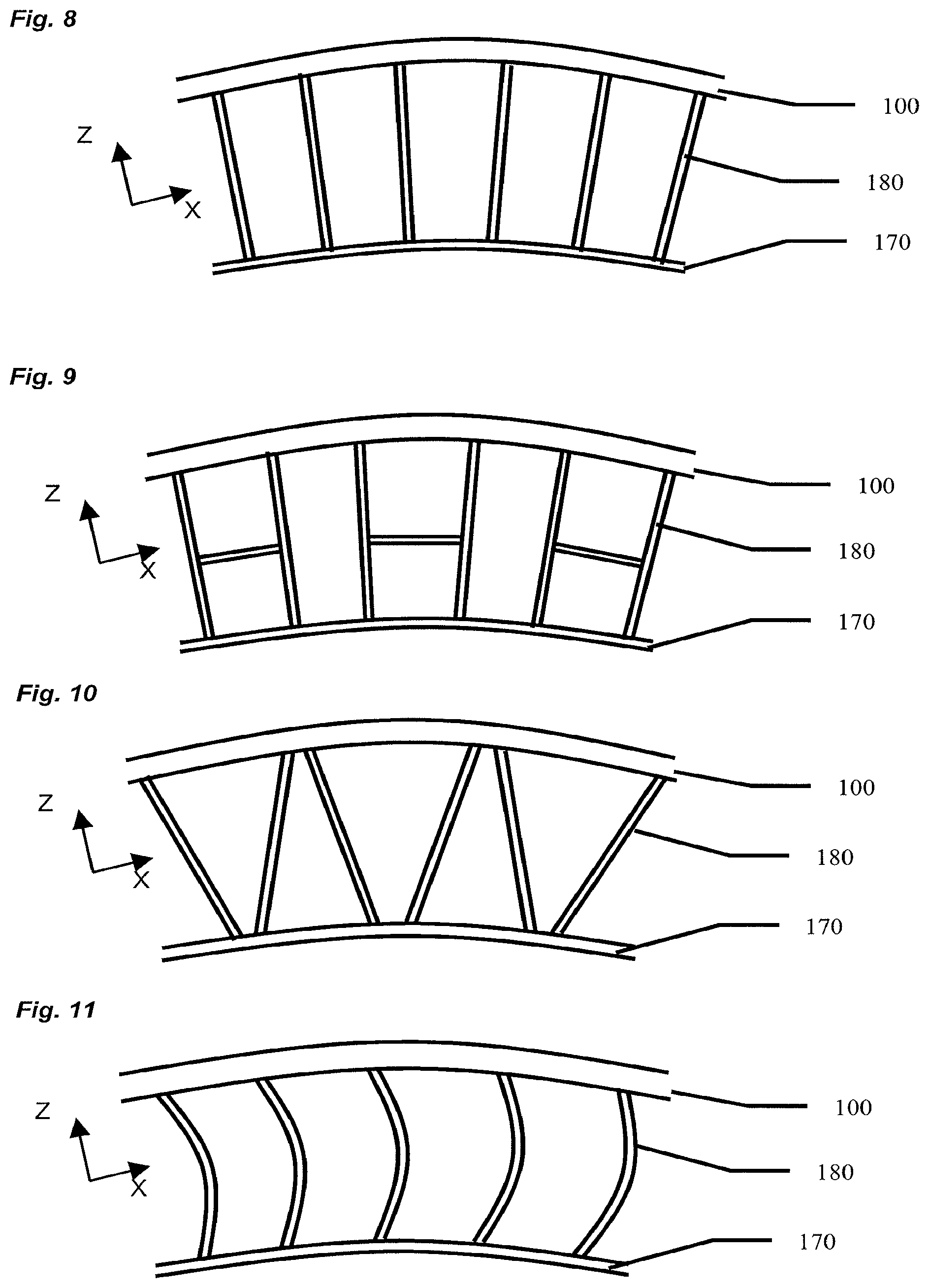
Many different spoke web designs are possible. While not exhaustive, four general patterns are shown in the tire x-z equatorial plane in FIGS. 8, 9, 10, and 11. In each figure, web spokes 180 connect a hub 170 to an annular beam 100. FIG. 8 shows a radial pattern. FIG. 9 is a design in which pairs of spokes are connected. FIG. 10 shows a diagonal pattern. FIG. 11 gives a curved radial design, in which the spokes have modest departures from the radial direction. The spokes can also be inclined relative to the axial direction and otherwise designed to facilitate demolding, which is most naturally done in the axial sense in the spoke web region. These designs, and others that result from combinations of these, are all intended to fall within the scope of this invention.
A preferred design practice will now be disclosed. The inventor has found relationships that relate the annular beam shear stiffness to bending stiffness, such that excellent contact patch behavior is achieved. This is done within the confines of a monolithic annular beam composed of a homogeneous material, yet having the aforementioned web geometry. When connected to a central wheel via webbed spokes, also previously described, the structure has a high load to mass ratio, yet keeps the simplicity of a homogeneous material, with no need for inextensible membranes or other composites or reinforcing elements.
A preferred tire contact pressure is substantially constant through the length L of the contact patch. To achieve this, an annular beam of radius R should be designed such that it develops a constant pressure when deformed to a flat surface. This is analogous to designing a straight beam which deforms to a circular arc of radius R when subjected to a constant pressure which is equal to the contact pressure of the aforementioned annular beam. However, a homogeneous beam of solid cross section does not behave like this. To create this desired performance, beam bending stiffness and beam shear stiffness can be intelligently designed using a web geometry. A method for doing so will now be disclosed, using standard nomenclature employed in typical engineering textbooks..sup.1
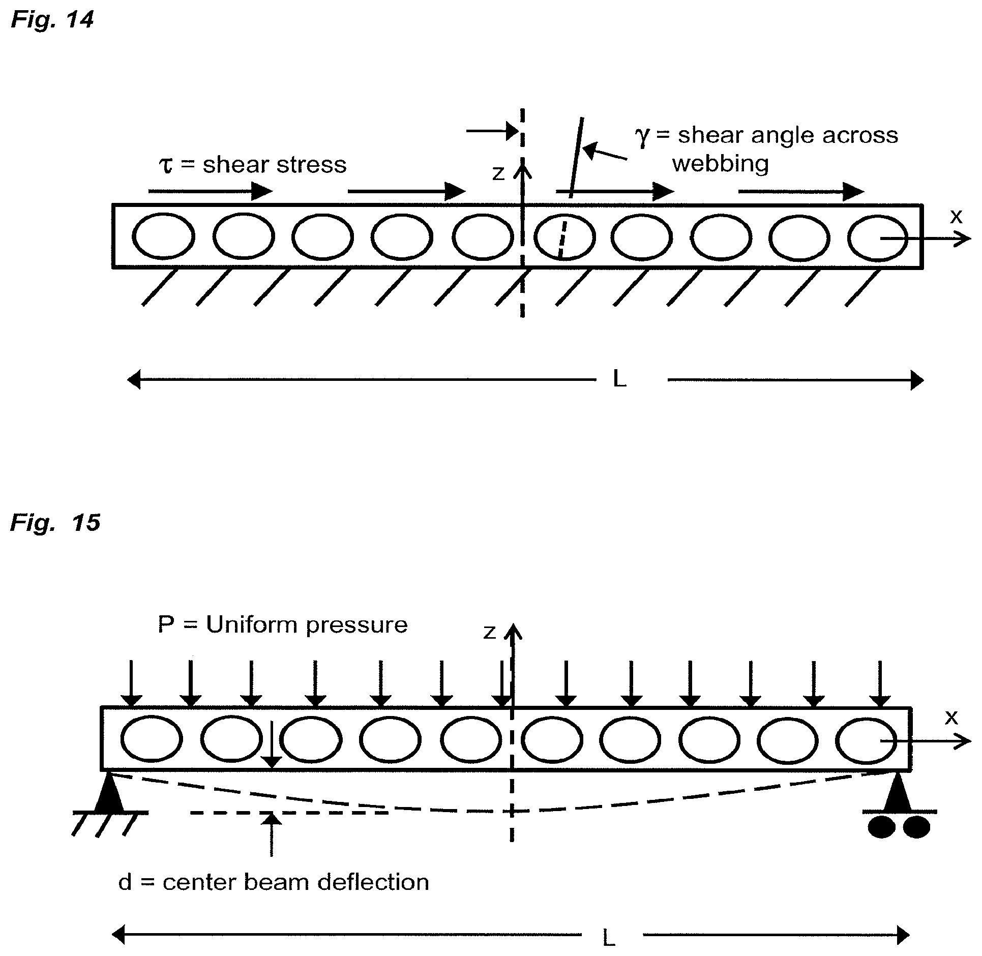
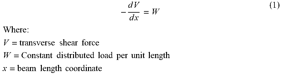
Equation 1 gives the relationship of shear force variation to an applied distributed load on a differential beam element:
.times..times..times..times..times..times..times..times..times..times..ti- mes..times..times..times..times..times..times..times..times..times..times.- .times..times..times..times..times..times..times..times..times..times..tim- es. ##EQU00001##
The deflection of such a beam due to shear deformation alone can be estimated by combining Equation 1 with other known relationships. This step is not taken by those of ordinary skill in the art of mechanics, as shear deflection is usually ignored in calculating beam deflections. Adding relations between shear force, shear stress, shear modulus, and cross-sectional area, Equation 2 can be derived:
.times..times..times..times..times..times..times..times..times..times..ti- mes..times..times..times..times..times..times..times..times..times..times.- .times..times..times..times..times..times..times. ##EQU00002##
For small deflections,
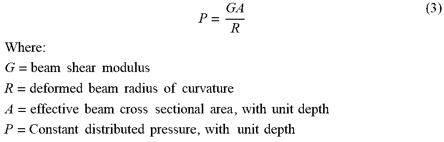
.times..times. ##EQU00003## is equal to the inverse of the beam deformed curvature. Making this substitution, which is not made by one of ordinary skill in the art, and considering a beam of unit depth, one obtains Equation 3:
.times..times..times..times..times..times..times..times..times..times..ti- mes..times..times..times..times..times..times..times..times..times..times.- .times..times..times..times..times..times..times..times..times..times..tim- es..times..times..times..times..times..times..times..times..times..times..- times..times. ##EQU00004##
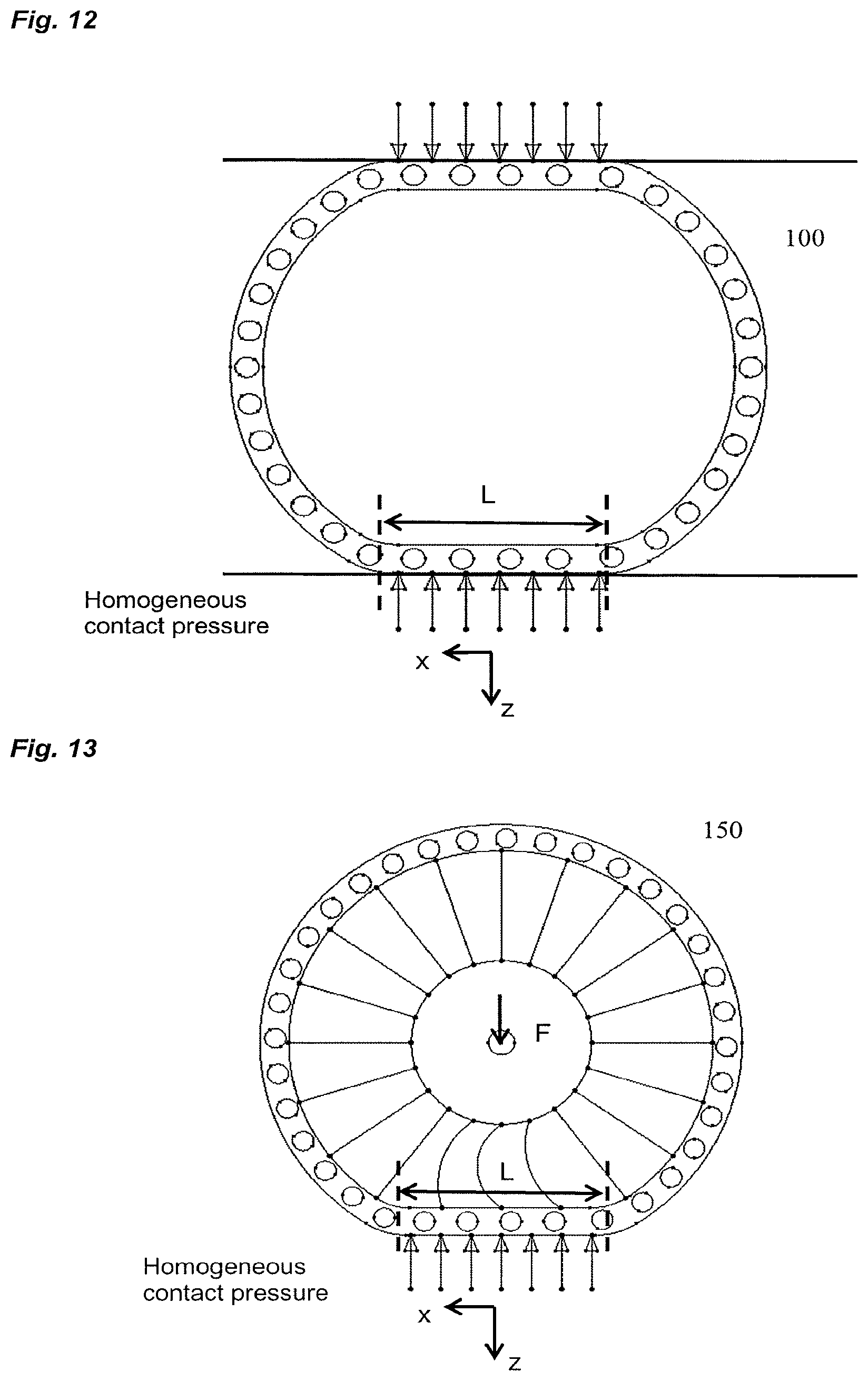
Equation 3 is very important. A straight beam of shear modulus G and effective cross sectional area A, subjected to homogeneous pressure P, will deform into the shape of an arc of radius R, provided shear deflection predominates.
Similarly, an annular beam of radius R, designed such that shear deformation predominates, that is deflected against a flat contact surface, will develop a homogeneous contact pressure P. This is shown in FIG. 12, in which an annular beam according to the invention is placed in contact between two parallel plates. Along a design contact length L, a constant contact pressure is developed. As mentioned, this is analogous to the straight beam that deforms to the shape of an arc of radius R, which subjected to the homogeneous pressure P.
A constant pressure through design contact length L is a highly desired performance attribute. An annular beam with this attribute could be advantageously employed in conveyor belt systems, and wheels used in track drive systems which have opposing contact patches. It is particularly useful when embodied in a non-pneumatic tire, as shown in FIG. 13. Here, the annular beam is attached to a central hub by a spoke web geometry. When a design load is applied at the hub, the beam deforms over a design contact patch length L, develops a homogeneous contact pressure, and passes the load to the hub via tension in the web spokes.
The present invention achieves the desired performance of FIG. 13 by designing the annular beam with a web structure that generally traverses the beam in the axial direction. With this design feature, shear deflection can be larger than bending deflection, and the desired contact patch performance can be obtained.
The inventor has found that analysis of a straight beam is less cumbersome than an annular beam; therefore the first part of the design process employs a straight beam geometry subjected to a constant pressure, in order to design the web structure. Final design verification then includes a complete model, as will be disclosed.
Towards this end, the first step in developing a design process is to calculate the deflection due to bending and the deflection due to shear of a simply supported straight beam subjected to a constant pressure. Equation 4 gives the center deflection due to bending; Equation 5 gives the center deflection due to shear; Equation 6 solves for shear deflection divided by bending deflection:
.times..times..times..times..times..times..times..times..times..times..ti- mes..times..times..times..times..times..times..times..times..times..times.- .times..times..times..times..times..times..times..times..times..times..tim- es..times..times..times..times..times..times..times..times..times..times..- times..times..times..times..times..times..times..times..times..times..time- s..times..times..times..times..times..times..times..times..times..times..t- imes..times..times..times..times..times. ##EQU00005##
The result of Equation (6) is a dimensionless term that describes an important aspect of the annular beam behavior. It is a geometrical term that, for homogeneous materials, is independent of modulus. As z.sub.s/z.sub.b becomes larger, shear deflection predominates. As shear deflection predominates, Equation (3) becomes valid and the desired performance of FIG. 13 is obtained.
Shear deflection is usually assumed to be large compared to bending deflection, and shear deflection is neglected. Consequently, one of ordinary skill in the art of mechanics is not familiar with the result of Equation (6). Beam bending stiffness must be relatively high, and beam shear stiffness must be relatively low in order to have z.sub.s/z.sub.b be acceptably high.
The next step is to define a procedure to relate beam design variables to the terms of Equation 6. This is accomplished by a Finite Element Analysis (FEA) on the geometry of the annular beam. While many standard FEA packages are suitable for this analysis, Abaqus was used for analyses in this application. To analyze the annular beam design, the following steps were followed: Representation of the annular beam as a 2D straight beam. Definition of the beam geometry. Beam length, L, equals the design tire contact patch length in the x direction. The beam webbing design and associated dimensions are also included as model parameters. Two small-deflection plane stress 2D FEA calculations are performed. i. Effective shear modulus calculation. This is done by constraining the bottom side of the beam and applying a uniform shear force to the top face. ii. Total center beam deflection calculation. This is done by simply supporting the beam and applying a uniform pressure to the top face such that the beam deflects in the z axis.
FEM used in (i) and (ii) are illustrated in FIGS. 14 and 15, respectively.
From the FEM output of the model of FIG. 15, the beam effective shear modulus can be determined:
.times..tau..gamma..times..times..times..times..times..tau..times..times.- .times..times..times..times..times..times..times..times..times..times..tim- es..times..gamma..times..times..times..times..times..times..times..times..- times..times..times..times..times..times..times..times..times..times..time- s..times..times..times..times..times..times. ##EQU00006##
The effective shear modulus calculation is used with Equation (5) to calculate z.sub.s, the beam center deflection due to shear. For a unit depth assumption with the plane stress FEM, the effective beam cross sectional area A for shear deformation calculation equals the beam webbing thickness in the z direction. The webbing between the two continuous bands is much softer in shear than the bands; therefore, the shear strain is higher in the webbing. Since beam deflections in shear depend on the largest shear angle which lies in the beam section, the effective beam cross section area is calculated relative to the total webbing thickness in the z axis.
The second FEA model calculates the total center beam center deflection. By subtracting the deflection due to shear, the deflection due to bending is found. Equation (4) is rearranged to calculate the effective moment of inertia of the beam:
.times..times..times..times..times..times..times..times..times..times..ti- mes..times..times..times..times..times..times..times..times..times..times.- .times..times..times..times..times..times..times..times..times. ##EQU00007##
For homogeneous, isotropic materials, the shear modulus and tensile modulus are related by Poisson's ratio, as given in Equation (10):
.times..times..upsilon..times..times..times..times..times..upsilon..times- ..times..times..times..times..times..times..times..times..times..times. ##EQU00008##
With the effective beam moment of inertia and the effective beam cross-sectional area known, the designer can then model the performance of an annular beam of the same design when used in the context of the present invention. The design procedure is then used to optimize the beam webbing design by employing Equation (6) to calculate the ratio of shear deflection to bending deflection for any design contact patch length L.
An efficient way to employ the FE models of FIGS. 14 and 15 is to normalize the tensile modulus to 1.0. The shear modulus is then defined by Equation (10). In most FE codes, this value can be input as modulus, along with a value for Poisson's ratio. For many thermoplastic and cast elastomers, this dimensionless value is approximately 0.45. Thus, for a normalized tensile modulus, the shear modulus equals about 0.344. A straight-forward example of this design method is now provided.
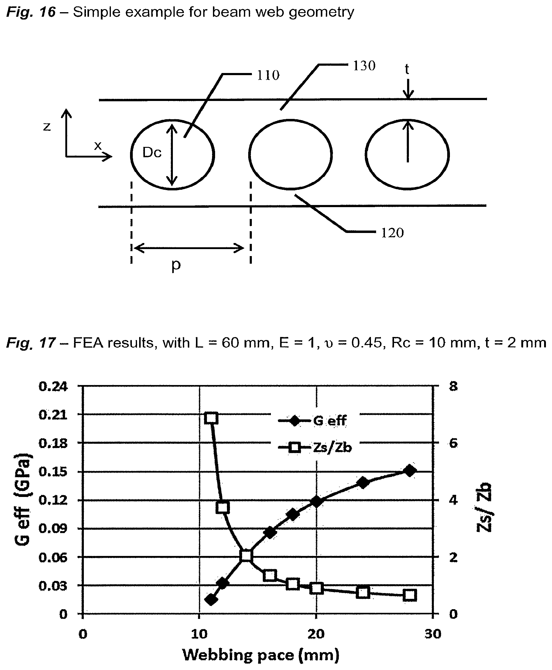
A simple web design is used in order to illustrate the design procedure. Other web designs could consist of additional variables and more complex geometries. The FEA beam model geometry of FIG. 16 depicts a web structure 110 consisting of circular cut-outs of diameter Dc, with a pace in the x direction between each cut-out of distance p. This web structure is between continuous bands 120 and 130 of thickness t in the z direction. As the distance between the web cutouts decreases, the amount of material removed increases. Therefore, the effective shear modulus decreases. As the distance p approaches cut-out diameter Dc, the shear stiffness approaches zero.
The bending stiffness also decreases as webbing material is removed. However, the bending stiffness does not decrease as rapidly as does the shear stiffness because of the maintenance of the two solid bands of thickness t at the beam outer fibers. A large moment of inertia, therefore, is maintained. For this reason, the shear deflection will become large compared to the bending deflection as the webbing pace is decreased.
FIG. 17 shows FEA results for effective shear modulus G.sub.eff, and the ratio of shear deflection to bending deflection z.sub.s/z.sub.b. as functions of the webbing pace p. The FE models used a tensile modulus normalized to 1.0, and therefore a shear modulus of 0.344. For this example, Dc=10 mm, t=2 mm, and L=60 mm.
For a webbing pace that is very large, the effective shear modulus will asymptotically approach the isotropic value of 0.344. As the webbing pace decreases to 10.0, the effective shear modulus approaches 0. The reason for this is that, when the webbing pace equals the radius of the cutout, the beam becomes discontinuous through the thickness. The resulting structure would be free to displace in shear with no shear force, and the effective shear modulus would be zero. With a webbing pace of 12 mm, there is 2 mm of material between the webbing cutouts, and the resulting G.sub.eff is 0.033, which represents a decrease of more than an order of magnitude compared to the isotropic shear modulus of 0.344.
For a webbing pace above 20 mm, the bending deflection becomes larger than the shear deflection. For a webbing pace of 14 mm or below, the shear deflection becomes significantly larger than the bending deflection. In this design region, where shear deflection is high compared to bending deflection, the positive performance attributes shown in FIG. 12 will be attained.
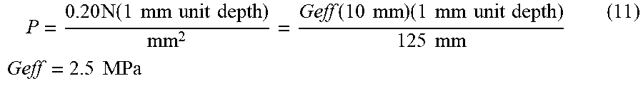
For a specific example, a small tire having an outer radius of 125 mm can be designed using an annular beam as in FIG. 16, with p=12 mm, t=2 mm, and Dc=10 mm. A design contact patch pressure of 0.20 MPa (30 psi) is used as a design input, along with a contact patch length L=60 mm. To attain this value in the design, Equation (3) is used to solve for the needed effective shear stiffness. With a unit depth, the effective shear area of the annular beam used in the FEM results from FIG. 17 is the webbing thickness in the z direction times unit depth. Thus:
.times..times..times..function..times..times..times..times..times..times.- .function..times..times..times..times..times..times..times..times..times..- times..times..times..times..times..times. ##EQU00009##
For a webbing pace=12 mm, G.sub.eff=0.033 for the normalized modulus of FIG. 17. Therefore, the desired actual shear modulus is:
.times..times..times..times. ##EQU00010## From Equation (10) the tensile modulus of the material is should be about 210 MPa.
Therefore, by choosing a homogeneous material with a tensile modulus of 210 MPa, a contact patch pressure of 0.20 MPa will be obtained. The contact length of 60 mm has already been defined as an input to the FE analyses. The design load carrying capacity is defined by multiplying pressure by contact area. For a lawn mower tire, a design load of 1115 N (250 lbs) is required. Thus:
.times..times..times..times..times..times..times..times..times..times..ti- mes..times..times..times..times..times..times..times..times..times..times.- .times..times..times..times..times..times..times..times..times..times..tim- es..times..times..times..times..times..times..times..times..times..times..- times..times..times..times..times..times..times..times..times. ##EQU00011##
The second phase involves verification of the annular beam design with a 2D plane stress FEM of a non-pneumatic tire. FIG. 17 shows the deformed geometry of a non-pneumatic tire according to the invention that has a web spacing of 12 mm, with the annular beam geometry as approximately defined in FIG. 16, and material properties about equal to those calculated above.
At a load of 1115 N (250 lbs), and a contact width in the depth direction of 95 mm, the predicted contact force is equally distributed through the contact length, as shown in FIG. 18. This result shows that a web spacing of 12 mm, and hence a z.sub.s/z.sub.b value of 3.8, does indeed give a shear deflection that is sufficiently high compared to bending deflection. Equation 3 becomes operative, and the contact patch pressure is essentially homogeneous.
Additional work by the inventor has shown that a z.sub.s/z.sub.b value of at least about 1.2, and preferably above 2.0, is necessary to obtain a relatively homogeneous pressure throughout the contact length.
This approximate tire size of 10 inch diameter.times.4 inch width (100 mm) is a common size used for lawn mower and other caster tires. A design load of 250 lbs per tire is very acceptable in this market.
FIG. 18 also shows the Von Mises stress distribution in the deformed geometry. The graduated gray scale of 0 MPa to 8 MPa shows that maximum values of less than 7.4 MPa are obtained with this web geometry at the design load. In order to sustain cyclic stress of this magnitude, a good flex fatigue performance is required. Further, tires are often subjected to impact loads and road hazard impacts that result in very high local strains. A material having a high level of tensile strain at break is desired. For some applications, a flex fatigue limit of 4 MPa is sufficient, with a value above 7 MPa preferred. A tensile strain at break of above 100% is also preferred. These must be combined with a tensile modulus of about 200 MPa.
Examples of materials having these physical characteristics include thermoplastic urethanes such as Elastollan S98A and thermoplastic co-polymers such as Hytrel G5544 and 5556. Some versions of unfilled, plasticized, toughened engineering plastics attain similar capabilities, such as Zytel 351PHS. Examples of cast polyurethane thermoset materials attaining these characteristics are COIM PET-95A and PET-60D, when cured with curative MBOCA or MCDEA. These are just a few of many examples and are not meant to limit the scope of invention in any way.
The design procedure covered in the preceding paragraphs is suitable for the design and optimization of a large variety of geometries falling within the scope of this application. The above example was a small tire suitable for a lawnmower, with a relatively short contact length. However, larger tires will have longer contact lengths. Equation (6) has the contact length as a squared term in the denominator. To maintain an acceptably high z.sub.s/z.sub.b, one strategy is to increase the beam moment of inertia, which is in the numerator of Equation (6).
Increasing the moment of inertia involves increasing the distance between the circumferentially continuous bands and/or increasing the band thickness. FIG. 4 showed one way to do this, while maintaining the relatively constant wall thicknesses required by thermoplastic injection. The tire shown in FIG. 4 has a total annular beam radial thickness that has been greatly increased, while wall thicknesses have been only moderately increased. The higher design load of this tire has been achieved largely due to changes in the geometry of the annular beam, with no need for inextensible membranes, plies, or composites.
Additional work by the inventor has shown that certain elastomeric materials exhibit favorable non-linear stress vs. strain characteristics. One preferred embodiment involves the choice of a material having a very non-linear material behavior, for which the secant modulus decreases with increasing strain. From the definition earlier provided, "modulus" is the initial slope of the stress vs. strain curve, often termed "Young's modulus" or "tensile modulus." Preferred materials have a high Young's modulus that is much greater than the secant modulus at 100% strain, which is often termed "the 100% modulus." This nonlinear behavior provides efficient load carrying during normal operation, yet enables impact loading and large local deflections without generating high stresses.
Some thermoset and thermoplastic polyurethanes have this material behavior. An example of such a favorable material is shown in FIG. 20. The measured stress vs. strain curve of COIM's PET-95A, with curative MCDEA, has a Young's modulus of 205 MPa. However, the secant modulus at 100% strain is only 19 MPa. This is a favorable attribute for the present invention; when following the design principles earlier disclosed, the tire normally operates in the 2 to 5% strain region. In this region, the material is moderately stiff and the slope of the stress vs. strain curve is fairly constant. However, if local deformation occurs due to road hazards or impacts, the material is capable of large strains, without generation of high stresses. This minimizes vehicle shock loading, and enhances tire durability.
Those skilled in the art of elastomer chemistry do not recognize the potential of this material behavior. Elastomers are often used in areas of high imposed strains. As such, testing protocol typically focuses on the performance at high strains, such as 100%, 200%, or more. Mechanical designs that carry load in tension and bending typically do not use one homogeneous elastomer--they employ reinforcements as well. This invention opens this new design space by leveraging this material non-linearity with a favorable mechanical design.
FIG. 21 shows an exemplary embodiment of a tire according to the invention for use in the construction industry. This large tire was designed using the above principles, along with the non-linear material behavior of COIM's PET-95A. With an outer diameter of 1500 mm (60 in) and width of 530 mm (21 in), the tire is capable of a design load of 10,000 kg (22,000 lbs.). It is a replacement for a pneumatic tire/wheel in the dimension 20.5.times.25. In this embodiment, the tread, circumferential band, spokes, and hub are all composed of PET-95A. The contact pressure was designed at 0.5 MPa (74 psi). The circumferentially continuous bands have a thickness of 15 mm (0.6 inches), and the web thickness is 85 mm (3.4 inches). Simulated impact loadings do not result in high material stresses, due to the non-linear stress vs. strain curve, while material strains are in the 2-5% range during normal operation. Total weight of this non-pneumatic tire/wheel is 275 kg (595 lbs.). This weight is less than the mounted assembly weight of pneumatic tires of similar size and design load. Vertical stiffness and contact pressure are designed to be similar to the comparable pneumatic tire.
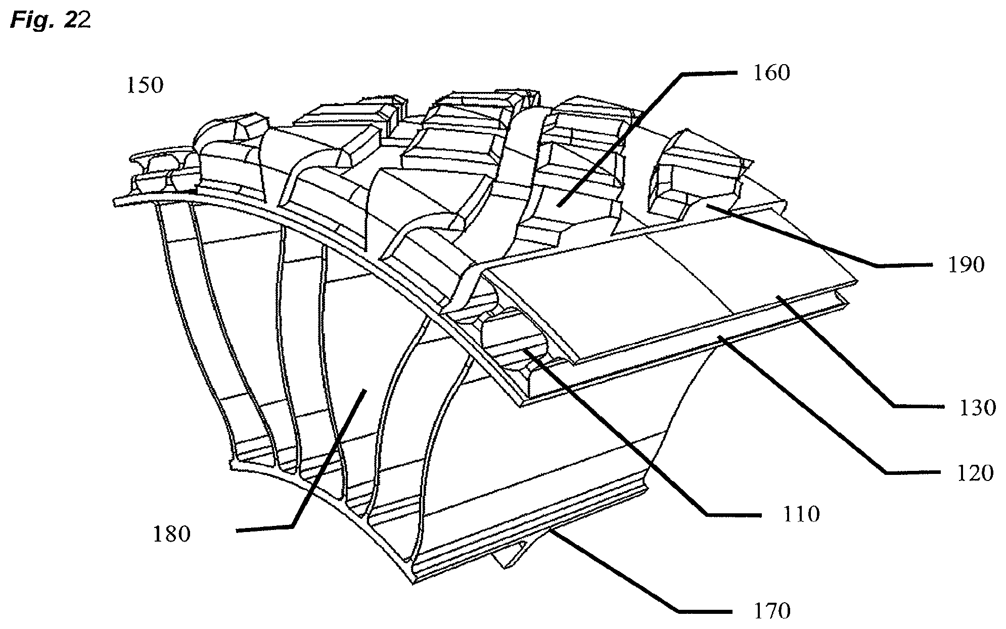
A tread contacting region can be affixed to a radially outer extent of the annular beam in many ways. The tread can be composed of a different material and can extend around the part or all of the axial extents of the annular beam. This is shown in FIG. 22. The tread is designed such that the annular beam web portion 110 is encapsulated and covered by the tread material 190. Additionally, the lateral extents of the web area have been modified to mate with and indeed provide mechanical interlocking for the tread material. In this design, the web portion is protected from rocks, dirt, or other debris, This illustrates one preferred embodiment, yet is not intended to limit the scope of the claim of this application.
The design procedure previously described can be represented as a decision flow-chart, shown in FIG. 23. Using this approach, a human designer or a computer algorithm can optimize a given annular beam web design for a specific design requirement as embodied in a non-pneumatic tire.
While certain exemplary embodiments have been described and shown in the accompanying drawings, it is to be understood that such embodiments are merely illustrative of and not restrictive on the broad invention, and that this invention not be limited to the specific constructions and arrangements shown and described, since various other changes, combinations, omissions, modifications and substitutions, in addition to those set forth in the above paragraphs, are possible. Those skilled in the art will appreciate that various adaptations, combinations, and modifications of the just described embodiments can be configured without departing from the scope and spirit of the invention.
REFERENCES
1. Muvdi, B. B., McNabb, J. W., (1980). Engineering Mechanics of Materials, Macmillan Publishing Co., Inc., New York, N.Y., "Shear and Bending Moment in Beams," pp 23-31, and "Deflections of Beams", pp 266-333.
* * * * *
D00000
D00001
D00002
D00003
D00004
D00005
D00006
D00007
D00008
D00009
D00010
D00011
D00012

M00001
M00002

M00003

M00004
M00005

M00006

M00007

M00008

M00009
M00010

M00011

XML
uspto.report is an independent third-party trademark research tool that is not affiliated, endorsed, or sponsored by the United States Patent and Trademark Office (USPTO) or any other governmental organization. The information provided by uspto.report is based on publicly available data at the time of writing and is intended for informational purposes only.
While we strive to provide accurate and up-to-date information, we do not guarantee the accuracy, completeness, reliability, or suitability of the information displayed on this site. The use of this site is at your own risk. Any reliance you place on such information is therefore strictly at your own risk.
All official trademark data, including owner information, should be verified by visiting the official USPTO website at www.uspto.gov. This site is not intended to replace professional legal advice and should not be used as a substitute for consulting with a legal professional who is knowledgeable about trademark law.