Lane marking localization and fusion
Wang , et al. May 18, 2
U.S. patent number 11,009,356 [Application Number 16/184,926] was granted by the patent office on 2021-05-18 for lane marking localization and fusion. This patent grant is currently assigned to TUSIMPLE, INC.. The grantee listed for this patent is TuSimple, Inc.. Invention is credited to Xue Mei, Chenzhe Qian, Mingdong Wang.


| United States Patent | 11,009,356 |
| Wang , et al. | May 18, 2021 |
Lane marking localization and fusion
Abstract
Various embodiments of the present disclosure provide a system and method for iterative lane marking localization that may be utilized by autonomous or semi-autonomous vehicles traveling within the lane. In an embodiment, the system comprises a locating device adapted to determine the vehicle's geographic location; a database; a region map; a response map; a plurality of cameras; and a computer connected to the locating device, database, and cameras, wherein the computer is adapted to receive the region map, wherein the region map corresponds to a specified geographic location; generate the response map by receiving information from the camera, the information relating to the environment in which the vehicle is located; identifying lane markers observed by the camera; and plotting identified lane markers on the response map; compare the response map to the region map; and iteratively generate a predicted vehicle location based on the comparison of the response map and the region map.
| Inventors: | Wang; Mingdong (San Diego, CA), Qian; Chenzhe (San Diego, CA), Mei; Xue (San Diego, CA) | ||||||||||
|---|---|---|---|---|---|---|---|---|---|---|---|
| Applicant: |
|
||||||||||
| Assignee: | TUSIMPLE, INC. (San Diego,
CA) |
||||||||||
| Family ID: | 1000005559823 | ||||||||||
| Appl. No.: | 16/184,926 | ||||||||||
| Filed: | November 8, 2018 |
Prior Publication Data
| Document Identifier | Publication Date | |
|---|---|---|
| US 20200271453 A1 | Aug 27, 2020 | |
Related U.S. Patent Documents
| Application Number | Filing Date | Patent Number | Issue Date | ||
|---|---|---|---|---|---|
| 15896077 | Feb 14, 2018 | ||||
| Current U.S. Class: | 1/1 |
| Current CPC Class: | G01C 21/30 (20130101) |
| Current International Class: | G05D 1/02 (20200101); G06F 17/10 (20060101); G06G 7/78 (20060101); G01C 21/30 (20060101) |
References Cited [Referenced By]
U.S. Patent Documents
| 6084870 | July 2000 | Wooten et al. |
| 6263088 | July 2001 | Crabtree et al. |
| 6594821 | July 2003 | Banning et al. |
| 6777904 | August 2004 | Degner et al. |
| 6975923 | December 2005 | Spriggs |
| 7103460 | September 2006 | Breed |
| 7689559 | March 2010 | Canright et al. |
| 7742841 | June 2010 | Sakai et al. |
| 7783403 | August 2010 | Breed |
| 7844595 | November 2010 | Canright et al. |
| 8041111 | October 2011 | Wilensky |
| 8064643 | November 2011 | Stein et al. |
| 8082101 | December 2011 | Stein et al. |
| 8164628 | April 2012 | Stein et al. |
| 8175376 | May 2012 | Marchesotti et al. |
| 8271871 | September 2012 | Marchesotti |
| 8346480 | January 2013 | Trepagnier et al. |
| 8378851 | February 2013 | Stein et al. |
| 8392117 | March 2013 | Dolgov et al. |
| 8401292 | March 2013 | Park et al. |
| 8412449 | April 2013 | Trepagnier et al. |
| 8478072 | July 2013 | Aisaka et al. |
| 8553088 | October 2013 | Stein et al. |
| 8706394 | April 2014 | Trepagnier et al. |
| 8718861 | May 2014 | Montemerlo et al. |
| 8788134 | July 2014 | Litkouhi et al. |
| 8908041 | December 2014 | Stein et al. |
| 8917169 | December 2014 | Schofield et al. |
| 8963913 | February 2015 | Baek |
| 8965621 | February 2015 | Urmson et al. |
| 8981966 | March 2015 | Stein et al. |
| 8983708 | March 2015 | Choe et al. |
| 8993951 | March 2015 | Schofield et al. |
| 9002632 | April 2015 | Emigh |
| 9008369 | April 2015 | Schofield et al. |
| 9025880 | May 2015 | Perazzi et al. |
| 9042648 | May 2015 | Wang et al. |
| 9081385 | July 2015 | Ferguson et al. |
| 9088744 | July 2015 | Grauer et al. |
| 9111444 | August 2015 | Kaganovich |
| 9117133 | August 2015 | Barnes et al. |
| 9118816 | August 2015 | Stein et al. |
| 9120485 | September 2015 | Dolgov |
| 9122954 | September 2015 | Srebnik et al. |
| 9134402 | September 2015 | Sebastian et al. |
| 9145116 | September 2015 | Clarke et al. |
| 9147255 | September 2015 | Zhang et al. |
| 9156473 | October 2015 | Clarke et al. |
| 9176006 | November 2015 | Stein |
| 9179072 | November 2015 | Stein et al. |
| 9183447 | November 2015 | Gdalyahu et al. |
| 9185360 | November 2015 | Stein et al. |
| 9191634 | November 2015 | Schofield et al. |
| 9214084 | December 2015 | Grauer et al. |
| 9219873 | December 2015 | Grauer et al. |
| 9233659 | January 2016 | Rosenbaum et al. |
| 9233688 | January 2016 | Clarke et al. |
| 9248832 | February 2016 | Huberman |
| 9248835 | February 2016 | Tanzmeister |
| 9251708 | February 2016 | Rosenbaum et al. |
| 9277132 | March 2016 | Berberian |
| 9280711 | March 2016 | Stein |
| 9282144 | March 2016 | Tebay et al. |
| 9286522 | March 2016 | Stein et al. |
| 9297641 | March 2016 | Stein |
| 9299004 | March 2016 | Lin et al. |
| 9315192 | April 2016 | Zhu et al. |
| 9317033 | April 2016 | Ibanez-Guzman et al. |
| 9317776 | April 2016 | Honda et al. |
| 9330334 | May 2016 | Lin et al. |
| 9342074 | May 2016 | Dolgov et al. |
| 9347779 | May 2016 | Lynch |
| 9355635 | May 2016 | Gao et al. |
| 9365214 | June 2016 | Ben Shalom et al. |
| 9399397 | July 2016 | Mizutani et al. |
| 9418549 | August 2016 | Kang et al. |
| 9428192 | August 2016 | Schofield et al. |
| 9436880 | September 2016 | Bos et al. |
| 9438878 | September 2016 | Niebla et al. |
| 9443163 | September 2016 | Springer |
| 9446765 | September 2016 | Ben Shalom et al. |
| 9459515 | October 2016 | Stein |
| 9466006 | October 2016 | Duan |
| 9476970 | October 2016 | Fairfield |
| 9483839 | November 2016 | Kwon et al. |
| 9490064 | November 2016 | Hirosawa et al. |
| 9494935 | November 2016 | Okumura et al. |
| 9507346 | November 2016 | Levinson et al. |
| 9513634 | December 2016 | Pack et al. |
| 9531966 | December 2016 | Stein et al. |
| 9535423 | January 2017 | Debreczeni |
| 9538113 | January 2017 | Grauer et al. |
| 9547985 | January 2017 | Tuukkanen |
| 9549158 | January 2017 | Grauer et al. |
| 9552657 | January 2017 | Ueno |
| 9555803 | January 2017 | Pawlicki et al. |
| 9568915 | February 2017 | Berntorp et al. |
| 9587952 | March 2017 | Slusar |
| 9599712 | March 2017 | Van Der Tempel et al. |
| 9600889 | March 2017 | Boisson et al. |
| 9602807 | March 2017 | Crane et al. |
| 9612123 | April 2017 | Levinson et al. |
| 9620010 | April 2017 | Grauer et al. |
| 9625569 | April 2017 | Lange |
| 9628565 | April 2017 | Stenneth et al. |
| 9649999 | May 2017 | Amireddy et al. |
| 9652860 | May 2017 | Maali et al. |
| 9669827 | June 2017 | Ferguson et al. |
| 9672446 | June 2017 | Vallespi-Gonzalez |
| 9690290 | June 2017 | Prokhorov |
| 9701023 | July 2017 | Zhang et al. |
| 9712754 | July 2017 | Grauer et al. |
| 9720418 | August 2017 | Stenneth |
| 9723097 | August 2017 | Harris et al. |
| 9723099 | August 2017 | Chen et al. |
| 9723233 | August 2017 | Grauer et al. |
| 9726754 | August 2017 | Massanell et al. |
| 9729860 | August 2017 | Cohen et al. |
| 9738280 | August 2017 | Rayes |
| 9739609 | August 2017 | Lewis |
| 9746550 | August 2017 | Nath et al. |
| 9753128 | September 2017 | Schweizer et al. |
| 9753141 | September 2017 | Grauer et al. |
| 9754490 | September 2017 | Kentley et al. |
| 9760837 | September 2017 | Nowozin et al. |
| 9766625 | September 2017 | Boroditsky et al. |
| 9769456 | September 2017 | You et al. |
| 9773155 | September 2017 | Shotton et al. |
| 9779276 | October 2017 | Todeschini et al. |
| 9785149 | October 2017 | Wang et al. |
| 9805294 | October 2017 | Liu et al. |
| 9810785 | November 2017 | Grauer et al. |
| 9823339 | November 2017 | Cohen |
| 9842399 | December 2017 | Yamaguchi |
| 9953236 | April 2018 | Huang et al. |
| 10147193 | December 2018 | Huang et al. |
| 10223806 | March 2019 | Luo et al. |
| 10223807 | March 2019 | Luo et al. |
| 10410055 | September 2019 | Wang et al. |
| 10816354 | October 2020 | Liu |
| 2001/0051845 | December 2001 | Itoh |
| 2003/0114980 | June 2003 | Klausner et al. |
| 2003/0174773 | September 2003 | Comaniciu et al. |
| 2004/0264763 | December 2004 | Mas et al. |
| 2007/0088497 | April 2007 | Jung |
| 2007/0183661 | August 2007 | El-Maleh et al. |
| 2007/0183662 | August 2007 | Wang et al. |
| 2007/0230792 | October 2007 | Shashua et al. |
| 2007/0286526 | December 2007 | Abousleman et al. |
| 2008/0109118 | May 2008 | Schwartz |
| 2008/0249667 | October 2008 | Horvitz et al. |
| 2009/0040054 | February 2009 | Wang et al. |
| 2009/0087029 | April 2009 | Coleman et al. |
| 2010/0049397 | February 2010 | Liu et al. |
| 2010/0082238 | April 2010 | Nakamura |
| 2010/0111417 | May 2010 | Ward et al. |
| 2010/0226564 | September 2010 | Marchesotti et al. |
| 2010/0281361 | November 2010 | Marchesotti |
| 2011/0142283 | June 2011 | Huang et al. |
| 2011/0206282 | August 2011 | Aisaka et al. |
| 2011/0247031 | October 2011 | Jacoby |
| 2012/0041636 | February 2012 | Johnson et al. |
| 2012/0105639 | May 2012 | Stein et al. |
| 2012/0140076 | June 2012 | Rosenbaum et al. |
| 2012/0274629 | November 2012 | Baek |
| 2012/0314070 | December 2012 | Zhang et al. |
| 2013/0051613 | February 2013 | Bobbitt et al. |
| 2013/0083959 | April 2013 | Owechko et al. |
| 2013/0182134 | July 2013 | Grundmann et al. |
| 2013/0204465 | August 2013 | Phillips et al. |
| 2013/0266187 | October 2013 | Bulan et al. |
| 2013/0329052 | December 2013 | Chew |
| 2014/0063489 | March 2014 | Steffey |
| 2014/0072170 | March 2014 | Zhang et al. |
| 2014/0104051 | April 2014 | Breed |
| 2014/0142799 | May 2014 | Ferguson et al. |
| 2014/0143839 | May 2014 | Ricci |
| 2014/0145516 | May 2014 | Hirosawa et al. |
| 2014/0198184 | July 2014 | Stein et al. |
| 2014/0321704 | October 2014 | Partis |
| 2014/0334668 | November 2014 | Saund |
| 2015/0062304 | March 2015 | Stein et al. |
| 2015/0127239 | May 2015 | Breed |
| 2015/0253428 | September 2015 | Holz |
| 2015/0269437 | September 2015 | Maruyama et al. |
| 2015/0269438 | September 2015 | Samarasekera et al. |
| 2015/0292891 | October 2015 | Kojo |
| 2015/0310370 | October 2015 | Burry et al. |
| 2015/0353082 | December 2015 | Lee et al. |
| 2016/0008988 | January 2016 | Kennedy et al. |
| 2016/0026787 | January 2016 | Nairn et al. |
| 2016/0037064 | February 2016 | Stein et al. |
| 2016/0046290 | February 2016 | Aharony et al. |
| 2016/0094774 | March 2016 | Li et al. |
| 2016/0118080 | April 2016 | Chen |
| 2016/0125608 | May 2016 | Sorstedt |
| 2016/0129907 | May 2016 | Kim et al. |
| 2016/0165157 | June 2016 | Stein et al. |
| 2016/0191860 | June 2016 | Jung |
| 2016/0210528 | July 2016 | Duan |
| 2016/0275766 | September 2016 | Venetianer et al. |
| 2016/0321381 | November 2016 | English et al. |
| 2016/0334230 | November 2016 | Ross et al. |
| 2016/0342837 | November 2016 | Hong et al. |
| 2016/0347322 | December 2016 | Clarke et al. |
| 2016/0375907 | December 2016 | Erban |
| 2017/0053169 | February 2017 | Cuban et al. |
| 2017/0061632 | March 2017 | Lindner et al. |
| 2017/0124476 | May 2017 | Levinson et al. |
| 2017/0134631 | May 2017 | Zhao et al. |
| 2017/0177951 | June 2017 | Yang et al. |
| 2017/0227647 | August 2017 | Baik |
| 2017/0301104 | October 2017 | Qian et al. |
| 2017/0305423 | October 2017 | Green |
| 2017/0318407 | November 2017 | Meister et al. |
| 2018/0005407 | January 2018 | Browning |
| 2018/0111274 | April 2018 | Seok |
| 2018/0131924 | May 2018 | Jung |
| 2018/0149739 | May 2018 | Becker |
| 2018/0151063 | May 2018 | Pun et al. |
| 2018/0158197 | June 2018 | Dasgupta et al. |
| 2018/0188043 | July 2018 | Chen |
| 2018/0216943 | August 2018 | Hawkins |
| 2018/0260956 | September 2018 | Huang et al. |
| 2018/0283892 | October 2018 | Behrendt |
| 2018/0284278 | October 2018 | Russell |
| 2018/0315201 | November 2018 | Cameron |
| 2018/0364717 | December 2018 | Douillard |
| 2018/0373254 | December 2018 | Song |
| 2018/0373980 | December 2018 | Huval |
| 2019/0025853 | January 2019 | Julian |
| 2019/0063945 | February 2019 | Liu |
| 2019/0065863 | February 2019 | Luo et al. |
| 2019/0066329 | February 2019 | Luo et al. |
| 2019/0066330 | February 2019 | Luo et al. |
| 2019/0108384 | April 2019 | Wang et al. |
| 2019/0132391 | May 2019 | Thomas et al. |
| 2019/0132392 | May 2019 | Liu et al. |
| 2019/0210564 | July 2019 | Han et al. |
| 2019/0210613 | July 2019 | Sun et al. |
| 2019/0226851 | July 2019 | Nicosevici |
| 2019/0236950 | August 2019 | Li et al. |
| 2019/0266420 | August 2019 | Ge et al. |
| 2019/0339084 | November 2019 | Korenaga |
| 2020/0271473 | August 2020 | Wang et al. |
| 106340197 | Jan 2017 | CN | |||
| 106781591 | May 2017 | CN | |||
| 108010360 | May 2018 | CN | |||
| 2608513 | Sep 1977 | DE | |||
| 0890470 | Jan 1999 | EP | |||
| 1754179 | Feb 2007 | EP | |||
| 2448251 | May 2012 | EP | |||
| 2463843 | Jun 2012 | EP | |||
| 2761249 | Aug 2014 | EP | |||
| 2918974 | Sep 2015 | EP | |||
| 2946336 | Nov 2015 | EP | |||
| 2993654 | Mar 2016 | EP | |||
| 3081419 | Oct 2016 | EP | |||
| 100802511 | Feb 2008 | KR | |||
| 1991009375 | Jun 1991 | WO | |||
| 2005098739 | Oct 2005 | WO | |||
| 2005098751 | Oct 2005 | WO | |||
| 2005098782 | Oct 2005 | WO | |||
| 2010109419 | Sep 2010 | WO | |||
| 2013045612 | Apr 2013 | WO | |||
| 2014111814 | Jul 2014 | WO | |||
| 2014166245 | Oct 2014 | WO | |||
| 2014201324 | Dec 2014 | WO | |||
| 2015083009 | Jun 2015 | WO | |||
| 2015103159 | Jul 2015 | WO | |||
| 2015125022 | Aug 2015 | WO | |||
| 2015186002 | Dec 2015 | WO | |||
| 2016090282 | Jun 2016 | WO | |||
| 2016135736 | Sep 2016 | WO | |||
| 2017013875 | Jan 2017 | WO | |||
| 2017079349 | May 2017 | WO | |||
| 2017079460 | May 2017 | WO | |||
| 2018132608 | Jul 2018 | WO | |||
| 2019040800 | Feb 2019 | WO | |||
| 2019084491 | May 2019 | WO | |||
| 2019084494 | May 2019 | WO | |||
| 2019140277 | Jul 2019 | WO | |||
| 2019168986 | Sep 2019 | WO | |||
| 2020097512 | May 2020 | WO | |||
Other References
|
Harry Y. Oh, U.S. Appl. No. 15/896,077, Non-Final Office Action dated Mar. 13, 2020, pp. 1-21. cited by applicant . Harry Y. Oh, U.S. Appl. No. 15/896,077, Final Office Action dated Jul. 9, 2020, pp. 1-30. cited by applicant . Harry Y. Oh, U.S. Appl. No. 15/896,077, Non-Final Office Action dated Oct. 1, 2020, pp. 1-34. cited by applicant . International application No. PCT/US2019/060547 International Search Report and Written Opinion, dated Jun. 25, 2020, pp. 1-23. cited by applicant . Carle, Patrick J.F., "Global Rover Localization by Matching Lidar and Orbital 3D Maps.", IEEE, Anchorage Convention Distriction, pp. 1-6, May 3-8, 2010. (Anchorage Alaska, US), May 3-8, 2019. cited by applicant . Young, Lee W., International Application No. PCT/US19/18113 Search Report and Written Opinion dated May 8, 2019. (pp. 1-13). cited by applicant . Caselitz, T. et al., "Monocular camera localization in 3D LiDAR maps," European Conference on Computer Vision (2014) Computer Vision--ECCV 2014. ECCV 2014. Lecture Notes in Computer Science, vol. 8690. Springer, Cham. cited by applicant . Mur-Artal, R. et al., "ORB-SLAM: A Versatile and Accurate Monocular SLAM System," IEEE Transaction on Robotics, Oct. 2015, pp. 1147-1163, vol. 31, No. 5, Spain. cited by applicant . Sattler, T. et al., "Are Large-Scale 3D Models Really Necessary for Accurate Visual Localization?" CVPR, IEEE, 2017, pp. 1-10. cited by applicant . Engel J., et al., LSD-SLAM: Large-Scale Direct Monocular SLAM. In: Fleet D., Pajdla T., Schiele B., Tuytelaars T. (eds) Computer Vision--ECCV 2014. ECCV 2014. Lecture Notes in Computer Science, vol. 8690. Springer, Cham. cited by applicant . Levinson, Jesse et al., Experimental Robotics, Unsupervised Calibration for Multi-Beam Lasers, pp. 179-194, 12th Ed., Oussama Khatib, Vijay Kumar, Gaurav Sukhatme (Eds.) Springer-Verlag Berlin Heidelberg 2014. cited by applicant . International Application No. PCT/US2019/013322, International Search Report and Written Opinion dated Apr. 2, 2019. cited by applicant . International Application No. PCT/US19/12934, International Search Report and Written Opinion dated Apr. 29, 2019. cited by applicant . International Application No. PCT/US18/53795, International Search Report and Written Opinion dated Dec. 31, 2018. cited by applicant . International Application No. PCT/US18/57484, International Search Report and Written Opinion dated Jan. 7, 2019. cited by applicant . International Application No. PCT/US2018/057851, International Search Report and Written Opinion dated Feb. 1, 2019. cited by applicant . International Application No. PCT/US2019/019839, International Search Report and Written Opinion dated May 23, 2019. cited by applicant . International Application No. PCT/US19/25995, International Search Report and Written Opinion dated Jul. 9, 2019. cited by applicant . Geiger, Andreas et al., "Automatic Camera and Range Sensor Calibration using a single Shot", Robotics and Automation (ICRA), pp. 1-8, 2012 IEEE International Conference. cited by applicant . Zhang, Z. et al. A Flexible new technique for camera calibration. IEEE Transactions on Pattern Analysis and Machine Intelligence ( vol. 22 , Issue: 11 , Nov. 2000). cited by applicant . International Application No. PCT/US2018/047830, International Search Report and Written Opinion dated Apr. 27, 2017. cited by applicant . Bar-Hillel, Aharon et al. "Recent progress in road and lane detection: a survey." Machine Vision and Applications 25 (2011): 727-745. cited by applicant . Schindler, Andreas et al. "Generation of high precision digital maps using circular arc splines," 2012 IEEE Intelligent Vehicles Symposium, Alcala de Henares, 2012, pp. 246-251. doi: 10.1109/IVS.2012.6232124. cited by applicant . International Application No. PCT/US2018/047608, International Search Report and Written Opinion dated Dec. 28, 2018. cited by applicant . Hou, Xiaodi and Zhang, Liqing, "Saliency Detection: A Spectral Residual Approach", Computer Vision and Pattern Recognition, CVPR'07--IEEE Conference, pp. 1-8, 2007. cited by applicant . Hou, Xiaodi and Harel, Jonathan and Koch, Christof, "Image Signature: Highlighting Sparse Salient Regions", IEEE Transactions on Pattern Analysis and Machine Intelligence, vol. 34, No. 1, pp. 194-201, 2012. cited by applicant . Hou, Xiaodi and Zhang, Liqing, "Dynamic Visual Attention: Searching for Coding Length Increments", Advances in Neural Information Processing Systems, vol. 21, pp. 681-688, 2008. cited by applicant . Li, Yin and Hou, Xiaodi and Koch, Christof and Rehg, James M. and Yuille, Alan L., "The Secrets of Salient Object Segmentation", Proceedings of the IEEE Conference on Computer Vision and Pattern Recognition, pp. 280-287, 2014. cited by applicant . Zhou, Bolei and Hou, Xiaodi and Zhang, Liqing, "A Phase Discrepancy Analysis of Object Motion", Asian Conference on Computer Vision, pp. 225-238, Springer Berlin Heidelberg, 2010. cited by applicant . Hou, Xiaodi and Yuille, Alan and Koch, Christof, "Boundary Detection Benchmarking: Beyond F-Measures", Computer Vision and Pattern Recognition, CVPR'13, vol. 2013, pp. 1-8, IEEE, 2013. cited by applicant . Hou, Xiaodi and Zhang, Liqing, "Color Conceptualization", Proceedings of the 15th ACM International Conference on Multimedia, pp. 265-268, ACM, 2007. cited by applicant . Hou, Xiaodi and Zhang, Liqing, "Thumbnail Generation Based on Global Saliency", Advances in Cognitive Neurodynamics, ICCN 2007, pp. 999-1003, Springer Netherlands, 2008. cited by applicant . Hou, Xiaodi and Yuille, Alan and Koch, Christof, "A Meta-Theory of Boundary Detection Benchmarks", arXiv preprint arXiv:1302.5985, 2013. cited by applicant . Li, Yanghao and Wang, Naiyan and Shi, Jianping and Liu, Jiaying and Hou, Xiaodi, "Revisiting Batch Normalization for Practical Domain Adaptation", arXiv preprint arXiv:1603.04779, 2016. cited by applicant . Li, Yanghao and Wang, Naiyan and Liu, Jiaying and Hou, Xiaodi, "Demystifying Neural Style Transfer", arXiv preprint arXiv:1701.01036, 2017. cited by applicant . Hou, Xiaodi and Zhang, Liqing, "A Time-Dependent Model of Information Capacity of Visual Attention", International Conference on Neural Information Processing, pp. 127-136, Springer Berlin Heidelberg, 2006. cited by applicant . Wang, Panqu and Chen, Pengfei and Yuan, Ye and Liu, Ding and Huang, Zehua and Hou, Xiaodi and Cottrell, Garrison, "Understanding Convolution for Semantic Segmentation", arXiv preprint arXiv:1702.08502, 2017. cited by applicant . Li, Yanghao and Wang, Naiyan and Liu, Jiaying and Hou, Xiaodi, "Factorized Bilinear Models for Image Recognition", arXiv preprint arXiv:1611.05709, 2016. cited by applicant . Hou, Xiaodi, "Computational Modeling and Psychophysics in Low and Mid-Level Vision", California Institute of Technology, 2014. cited by applicant . Spinello, Luciano, Triebel, Rudolph, Siegwart, Roland, "Multiclass Multimodal Detection and Tracking in Urban Environments", Sage Journals, vol. 29 Issue 12, pp. 1498-1515 Article first published online: Oct. 7, 2010; Issue published: Oct. 1, 2010. cited by applicant . Matthew Barth, Carrie Malcolm, Theodore Younglove, and Nicole Hill, "Recent Validation Efforts for a Comprehensive Modal Emissions Model", Transportation Research Record 1750, Paper No. 01-0326, College of Engineering, Center for Environmental Research and Technology, University of California, Riverside, CA 92521, date unknown. cited by applicant . Kyoungho Ahn, Hesham Rakha, "The Effects of Route Choice Decisions on Vehicle Energy Consumption and Emissions", Virginia Tech Transportation Institute, Blacksburg, VA 24061, date unknown. cited by applicant . Ramos, Sebastian, Gehrig, Stefan, Pinggera, Peter, Franke, Uwe, Rother, Carsten, "Detecting Unexpected Obstacles for Self-Driving Cars: Fusing Deep Learning and Geometric Modeling", arXiv:1612.06573v1 [cs.CV] Dec. 20, 2016. cited by applicant . Schroff, Florian, Dmitry Kalenichenko, James Philbin, (Google), "FaceNet: A Unified Embedding for Face Recognition and Clustering", CVPR 2015. cited by applicant . Dai, Jifeng, Kaiming He, Jian Sun, (Microsoft Research), "Instance-aware Semantic Segmentation via Multi-task Network Cascades", CVPR 2016. cited by applicant . Huval, Brody, Tao Wang, Sameep Tandon, Jeff Kiske, Will Song, Joel Pazhayampallil, Mykhaylo Andriluka, Pranav Rajpurkar, Toki Migimatsu, Royce Cheng-Yue, Fernando Mujica, Adam Coates, Andrew Y. Ng, "An Empirical Evaluation of Deep Learning on Highway Driving", arXiv:1504.01716v3 [cs.RO] Apr. 17, 2015. cited by applicant . Tian Li, "Proposal Free Instance Segmentation Based on Instance-aware Metric", Department of Computer Science, Cranberry-Lemon University, Pittsburgh, PA., date unknown. cited by applicant . Mohammad Norouzi, David J. Fleet, Ruslan Salakhutdinov, "Hamming Distance Metric Learning", Departments of Computer Science and Statistics, University of Toronto, date unknown. cited by applicant . Jain, Suyong Dutt, Grauman, Kristen, "Active Image Segmentation Propagation", In Proceedings of the IEEE Conference on Computer Vision and Pattern Recognition (CVPR), Las Vegas, Jun. 2016. cited by applicant . MacAodha, Oisin, Campbell, Neill D.F., Kautz, Jan, Brostow, Gabriel J., "Hierarchical Subquery Evaluation for Active Learning on a Graph", In Proceedings of the IEEE Conference on Computer Vision and Pattern Recognition (CVPR), 2014. cited by applicant . Kendall, Alex, Gal, Yarin, "What Uncertainties Do We Need in Bayesian Deep Learning for Computer Vision", arXiv:1703.04977v1 [cs.CV] Mar. 15, 2017. cited by applicant . Wei, Junqing, John M. Dolan, Bakhtiar Litkhouhi, "A Prediction- and Cost Function-Based Algorithm for Robust Autonomous Freeway Driving", 2010 IEEE Intelligent Vehicles Symposium, University of California, San Diego, CA, USA, Jun. 21-24, 2010. cited by applicant . Peter Welinder, Steve Branson, Serge Belongie, Pietro Perona, "The Multidimensional Wisdom of Crowds" http://www.vision.caltech.edu/visipedia/papers/WelinderEtaINIPS10.pdf, 2010. cited by applicant . C. Yang, Z. Li, R. Cui and B. Xu, "Neural Network-Based Motion Control of an Underactuated Wheeled Inverted Pendulum Model," in IEEE Transactions on Neural Networks and Learning Systems, vol. 25, No. 11, pp. 2004-2016, Nov. 2014. cited by applicant . Stephan R. Richter, Vibhav Vineet, Stefan Roth, Vladlen Koltun, "Playing for Data: Ground Truth from Computer Games", Intel Labs, European Conference on Computer Vision (ECCV), Amsterdam, the Netherlands, 2016. cited by applicant . Thanos Athanasiadis, Phivos Mylonas, Yannis Avrithis, and Stefanos Kollias, "Semantic Image Segmentation and Object Labeling", IEEE Transactions on Circuits and Systems for Video Technology, vol. 17, No. 3, Mar. 2007. cited by applicant . Marius Cordts, Mohamed Omran, Sebastian Ramos, Timo Rehfeld, Markus Enzweiler Rodrigo Benenson, Uwe Franke, Stefan Roth, and Bernt Schiele, "The Cityscapes Dataset for Semantic Urban Scene Understanding", Proceedings of the IEEE Computer Society Conference on Computer Vision and Pattern Recognition (CVPR), Las Vegas, Nevada, 2016. cited by applicant . Adhiraj Somani, Nan Ye, David Hsu, and Wee Sun Lee, "DESPOT: Online POMDP Planning with Regularization", Department of Computer Science, National University of Singapore, date unknown. cited by applicant . Adam Paszke, Abhishek Chaurasia, Sangpil Kim, and Eugenio Culurciello. Enet: A deep neural network architecture for real-time semantic segmentation. CoRR, abs/1606.02147, 2016. cited by applicant . Szeliski, Richard, "Computer Vision: Algorithms and Applications" http://szeliski.org/Book/, 2010. cited by applicant . Kyoungho Ahn, Hesham Rakha, "The Effects of Route Choice Decisions on Vehicle Energy Consumption and Emissions", Virginia Tech Transportation Institute, date unknown. cited by applicant . Office Action Mailed in Chinese Application No. 201810025516.X, dated Sep. 3, 2019. cited by applicant . Luo, Yi et al. U.S. Appl. No. 15/684,389 Notice of Allowance dated Oct. 9, 2019. cited by applicant . Kai Yu, Yang Zhou, Da Li, Zhang Zhang, Kaiqi Huang, "Large-scale Distributed Video Parsing and Evaluation Platform", Center for Research on Intelligent Perception and Computing, Institute of Automation, Chinese Academy of Sciences, China, arXiv:1611.09580v1 [cs.CV] Nov. 29, 2016. cited by applicant . P. Guarneri, G. Rocca and M. Gobbi, "A Neural-Network-Based Model for the Dynamic Simulation of the Tire/ Suspension System While Traversing Road Irregularities," in IEEE Transactions on Neural Networks, vol. 19, No. 9, pp. 1549-1563, Sep. 2008. cited by applicant. |
Primary Examiner: Oh; Harry Y
Attorney, Agent or Firm: Liu; Paul Perkins Coie, LLP
Parent Case Text
CROSS-REFERENCE TO RELATED APPLICATIONS
The present application is a continuation-in-part of, and claims priority to, U.S. patent application Ser. No. 15/896,077, filed on Feb. 14, 2018, entitled, "Lane Marking Localization," the entire disclosure of which is hereby fully incorporated herein.
Claims
We claim:
1. A method for determining a vehicle's location, comprising: approximating the vehicle's region; receiving a first region map from a database, wherein the first region map corresponds to the vehicle's approximated region and comprises a plurality of first region points indicating an expected roadway lane; receiving a second region map from the database, wherein the second region map corresponds to the vehicle's approximated region and comprises a plurality of second region points indicating the expected roadway lane; receiving a first response image generated by a first imaging device, the first response image comprising information relating to the vehicle's environment; receiving a second response image generated by a second imaging device, the second response image comprising information relating to the vehicle's environment; generating a first response map from the first response image, the first response map comprising a plurality of first response points indicating the vehicle's location; generating a second response map from the second response image, the second response map comprising a plurality of second response points indicating the vehicle's location; generating a first corrected location based on comparing the first response map to the first region map; generating a second corrected location based on comparing the second response map to the second region map; and predicting the vehicle's location based on the first corrected location and the second corrected location.
2. The method of claim 1, further comprising: receiving a third region map from the database, wherein the third region map corresponds to the vehicle's approximated region and comprises a plurality of third region points indicating the expected roadway lane; receiving a third response image generated by a third imaging device, the third response image comprising information relating to the vehicle's environment; generating a third response map from the third response image, the third response map comprising a plurality of third response points indicating the vehicle's location; and generating a third corrected location based on comparing the third response map to the third region map, wherein predicting the vehicle's location is further based on the third corrected location.
3. The method of claim 1, wherein the first region map comprises information from a previously generated vehicle location.
4. The method of claim 1, wherein the vehicle's region is approximated using a Global Positioning System (GPS) device or an inertial measurement unit (IMU).
5. The method of claim 1, wherein generating the first response map comprises: detecting lane markers in the first response image, the lane markers pertaining to physical aspects contained in the first response image; plotting the plurality of first response points on the first response map, the plurality of first response points indicating locations of the lane markers.
6. The method of claim 1, further comprising: generating a first confidence score based on comparing the first response map to the first region map.
7. The method of claim 1, wherein the response image is generated from radar sensing equipment, light detection and ranging (LIDAR) sensing equipment, Global Positioning System (GPS) sensing information, and/or images.
8. The method of claim 1, wherein the first region map and the first response map are compared at a selected frequency.
9. The method of claim 1, further comprising: outputting the vehicle's predicted location to an advanced driver-assistance system (ADAS).
10. The method of claim 2, wherein the first imaging device, the second imaging device, and the third imaging device are each adapted to perceive different aspects of the vehicle's environment.
11. A system for iteratively determining a vehicle's location on a roadway, comprising: a processor configured to: receive, from a locating device adapted to determine a vehicle's geographic region, the vehicle's predicted geographic region; receive, from a database, a first region map comprising a plurality of first region points corresponding to the vehicle's predicted geographic region; receive, from the database, a second region map comprising a plurality of second region points corresponding to the vehicle's predicted geographic region; receive, from a first imaging device, a first perceived information relating to the vehicle's environment; receive, from a second imaging device, a second perceived information relating to the vehicle's environment; generate a first response map based on the first perceived information, the first response map comprising a plurality of first response points corresponding to lane markers detected within the first response map; generate a second response map based on the second perceived information, the second response map comprising a plurality of second response points corresponding to lane markers detected within the second response map; generate a first corrected location based on comparing the first response map to the first region map; generate a second corrected location based on comparing the second response map to the second region map; and determine a fused vehicle location based on the first corrected location and the second corrected location.
12. The system of claim 11, wherein the fused vehicle location is further based on a previously determined vehicle location.
13. The system of claim 11, wherein the processor is further configured to: receive, from the database, a third region map comprising a plurality of third region points corresponding to the vehicle's predicted geographic region; receive, from a third imaging device, a third perceived information relating to the vehicle's environment; generate a third response map based on the third perceived information, the third response map comprising a plurality of third response points corresponding to lane markers detected within the third response map; and generate a third corrected location based on comparing the third response map to the third region map, wherein the fused vehicle location is further based on the third corrected location.
14. The system of claim 11, wherein the locating device comprises a Global Positioning System (GPS) device or an inertial measurement unit (IMU).
15. The system of claim 11, wherein the imaging device comprises a camera or a light detection and ranging (LIDAR) device.
16. The system of claim 11, wherein the processor is further configured to output the vehicle's predicted location to an advanced driver-assistance system (ADAS).
17. The system of claim 11, wherein the processor is further configured to determine a confidence score.
18. The system of claim 13, wherein the first imaging device, the second imaging device, and the third imaging device are each adapted to perceive different aspects of the vehicle's environment.
19. The system of claim 17, wherein the confidence score comprises a variance that is computed using a logistic function.
20. The system of claim 19, wherein the variance is computed as: .function. ##EQU00002## wherein x is a matching score of a corresponding response map, x.sub.min is a minimum value of the corresponding response map, x.sub.max is a maximum value of the corresponding response map, S is a steepness parameter, G is a growth rate parameter, and m is a midpoint of the corresponding response map.
Description
BACKGROUND OF THE INVENTION
1. Field of Invention
The present invention relates to GPS positioning and, more specifically, a system and method for fusing localizations upon a roadway.
2. Description of Related Art
Global positioning satellite ("GPS") technology is widely used as a means for locating an automobile upon a roadway. As autonomous and semi-autonomous vehicles become more advanced, accurately knowing the vehicle's position in the roadway becomes critical. For example, self-driving cars by Volvo and Tesla have been easily confused by faded lane markers and other shabby road conditions. Further, current GPS technology is inaccurate. To achieve a fully autonomous self-driving vehicle requires the ability of a computer to determine the vehicle's lateral position within a roadway with great precision. Additionally, advanced driver-assistance systems ("ADAS") benefit greatly from this ability. For example, lane keeping assistance ("LKA") systems, lane departure warning ("LDW") systems, and lane change assistance systems would be greatly benefited by accurately knowing the vehicle's lateral position within a lane. Other examples of ADAS systems include adaptive cruise control, adaptive light control, anti-lock braking systems, automatic parking, blind spot monitoring, collision avoidance systems, intersection detection, lane departure warning systems, parking sensors, turning assistance, and wrong-way driving warning.
A vehicle may utilize various levels of autonomous driving. For example, a first level of autonomous driving may assist a human driver during some driving tasks such as steering or engine acceleration/deceleration. A second level of autonomous driving may conduct some steering and acceleration/deceleration while the human driver monitors the driving environment and controls the remaining driving tasks. Such a system is referred to as a partially automated system. A third level of autonomous driving may conduct driving tasks and monitor the driving environment, but the human driver must be ready to retake control when the automated system requests. Such a system is generally referred to as a conditionally automated system. A fourth level of autonomous driving may drive the vehicle and monitor road conditions; the human driver does not need to take control but the system may only operate in specific conditions and environments such as inside of a factory, on a closed road course, or within a bounded area. Such a system is referred to as a highly automated system. A fifth level of autonomous driving may perform all driving and road-monitoring tasks in all driving conditions. Such a system is referred to as a fully-automated system.
Current technology relies on GPS technology to determine a vehicle's lateral position within a roadway. However, this method is susceptible to a high amount of drift--the lateral area around the vehicle that is within the technology's margin of error. The amount of drift in a given system is dependent on many factors including signal strength and the precision of the GPS hardware being used. Typical GPS devices aimed at the average consumer have a drift of about 10 meters. Even with the most precise instruments having the best signal strength, a system experiences a drift of 1-2 meters or more, which is unacceptable for self-driving vehicles.
To improve the accuracy of GPS positioning, current technology also employs an inertial measurement unit ("IMU"). An IMU is an electronic device that measures and reports a vehicle's specific force and angular rate using a combination of accelerometers and gyroscopes. However, even while being augmented with IMU's, current lateral locating methods and systems still experience a high amount of drift. For such a system to be useful in a self-driving vehicle, the resolution needs to be approximately 10 cm or less.
Therefore, what is needed is a system that can utilize GPS information and determine a vehicle's lateral position within a roadway with great accuracy. This need has heretofore remained unsatisfied.
SUMMARY OF THE INVENTION
The present invention overcomes these and other deficiencies of the prior art by providing a system and method for determining a vehicle's location within a roadway lane by comparing information relating to the vehicle's environment against regional information stored in a database. To improve the accuracy of the vehicle's predicted location, the present invention may further utilize previously determined predicted locations fused with vehicle's instant predicted location. In an exemplary embodiment, the present invention comprises a method for determining a vehicle's location comprising the steps of approximating the vehicle's region; receiving a region map from a database, wherein the region map corresponds to the vehicle's approximated region and comprises a plurality of region points indicating an expected roadway lane; receiving a first response image generated by a first imaging device, the first response image comprising information relating to the vehicle's environment; generating a first response map from the first response image, the first response map comprising a plurality of first response points indicating the vehicle's location; comparing the first response map to the region map; and predicting the vehicle's location based on the differences between the first response points and the region points.
In another exemplary embodiment, the present invention further comprises the steps of receiving a second response image generated by a second imaging device, the second response image comprising information relating to the vehicle's environment; generating a second response map from the second response image, the second response map comprising a plurality of second response points indicating the vehicle's location; and comparing the second response map to the region map; wherein the step of predicting the vehicle's location further comprises comparing the differences between the second response points, the first response points, and the region points.
In another exemplary embodiment, the present invention further comprises the steps of receiving a third response image generated by a third imaging device, the third response image comprising information relating to the vehicle's environment; generating a third response map from the third response image, the third response map comprising a plurality of third response points indicating the vehicle's location; and comparing the third response map to the region map; wherein the step of predicting the vehicle's location further comprises comparing the differences between the third response points, second response points, the first response points, and the region points.
In another exemplary embodiment, the vehicle's region may be approximated using a GPS device or an IMU device.
In another exemplary embodiment, the step of generating a response map may further comprises the steps of detecting lane markers in the response image, the lane markers pertaining to physical aspects contained in the response image; and plotting the response points on the response map, the response points indicating locations of the lane markers.
In another exemplary embodiment, the present invention may further comprise the step of generating a confidence score.
In another exemplary embodiment, the response image may be generated from radar sensing equipment, LIDAR sensing equipment, GPS sensing information, and/or images.
In another exemplary embodiment, the region map and response map may be compared at a selected frequency.
In another exemplary embodiment, the selected frequency may be at least 20 cycles per second.
In another exemplary embodiment, the present invention may further comprise the step of outputting the vehicle's predicted location to an ADAS.
In another exemplary embodiment, the first imaging device, the second imaging device, and the third imaging device may be each adapted to perceive different aspects of the vehicle's environment.
In another exemplary embodiment, the present invention comprises a system for determining a vehicle's location on a roadway comprising a locating device adapted to determine a vehicle's geographic region; a database comprising a plurality of region maps, the region maps comprising a plurality of region points; a first imaging device adapted to perceive information relating to the vehicle's environment; a processor operably connected to the locating device, the database, and the first imaging device, the processor, at a predetermined frequency, adapted to receive, from the locating device, the vehicle's determined geographic region; receive, from the database, the region map corresponding to the vehicle's determined geographic region; receive, from the first imaging device, information perceived relating to the vehicle's environment; generate a first response map, the first response map comprising a plurality of first response points corresponding to lane markers detected within the first response map; compare the first response map to the region map; and determine the vehicle's predicted location based on the comparison of the region map and the first response map.
In another exemplary embodiment, the processor may be further configured to generate a fused vehicle location comprising the vehicle's predicted location and a previously determined vehicle location.
In another exemplary embodiment, the present invention may further comprise a second imaging device adapted to perceive information relating to the vehicle's environment; wherein the processor is further adapted to receive, from the second imaging device, information perceived relating to the vehicle's environment; generate a second response map, from the second response map comprising a plurality of second response points corresponding to lane markers detected within the second response map; and determine the vehicle's predicted location based on the comparison of the region map, the first response map, and the second response map.
In another exemplary embodiment, the present invention may further comprise a third imaging device adapted to perceive information relating to the vehicle's environment; wherein the processor is further adapted to receive, from the third imaging device, information perceived relating to the vehicle's environment; generate a third response map, from the third response map comprising a plurality of third response points corresponding to lane markers detected within the third response map; and determine the vehicle's predicted location based on the comparison of the region map, the first response map, the second response map, and the third response map.
In another exemplary embodiment, the locating device may comprise a GPS device or an IMU device.
In another exemplary embodiment, the imaging device may comprise a camera or a LIDAR device.
In another exemplary embodiment, the predetermined frequency may be at least 20 cycles per second.
In another exemplary embodiment, the processor may be further configured to output the vehicle's predicted location to an ADAS.
In another exemplary embodiment, the processor may be further configured to determine a confidence score.
In another exemplary embodiment, the first imaging device, the second imaging device, and the third imaging device may be each adapted to perceive different aspects of the vehicle's environment.
BRIEF DESCRIPTION OF THE DRAWINGS
For a more complete understanding of the present invention, the objects and advantages thereof, reference is now made to the ensuing descriptions taken in connection with the accompanying drawings briefly described as follows:
FIG. 1 illustrates a flowchart showing the exemplary steps of lane marking localization and fusion, according to an exemplary embodiment of the present disclosure;
FIG. 2 illustrates a flowchart showing exemplary steps of localizing, according to an exemplary embodiment of the present disclosure;
FIG. 3 illustrates a flowchart showing exemplary steps for fusing predicted locations, according to an exemplary embodiment of the present disclosure;
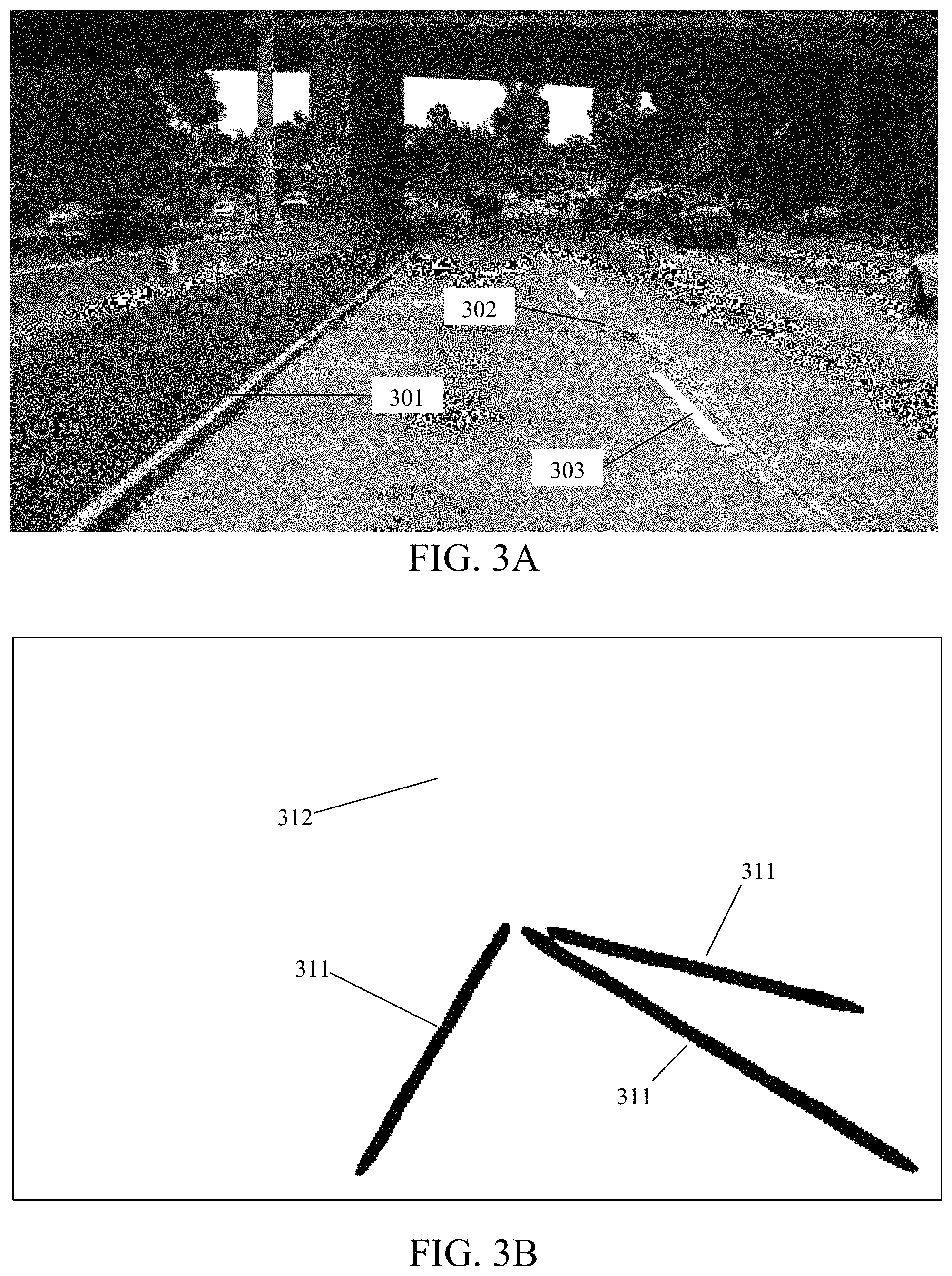
FIG. 3A illustrates an image taken from a vehicle's onboard camera, according to an exemplary embodiment of the present disclosure;
FIG. 3B illustrates a response map generated by the system, according to an exemplary embodiment of the present disclosure;
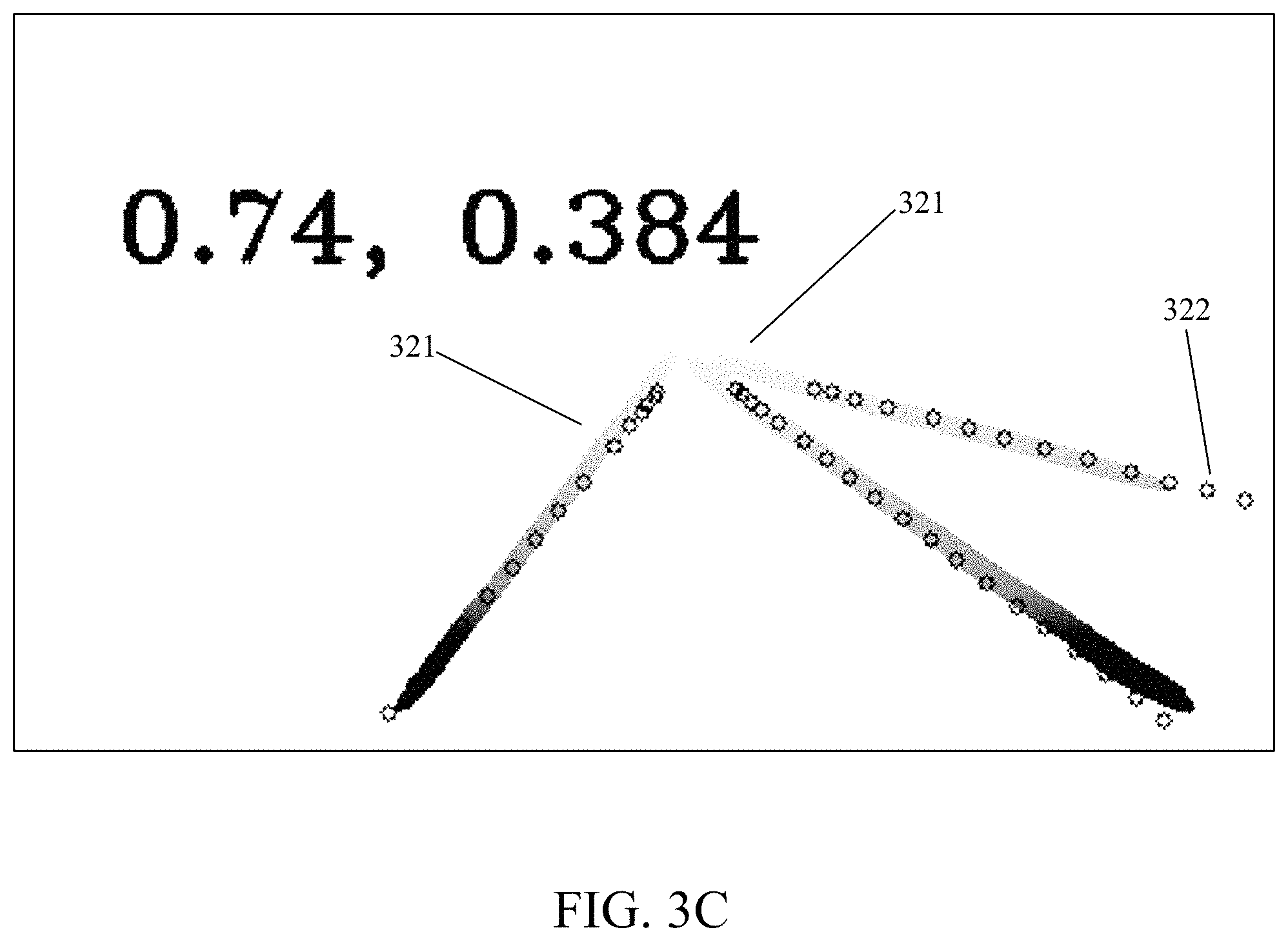
FIG. 3C illustrates a score calculation, according to an exemplary embodiment of the present disclosure; and
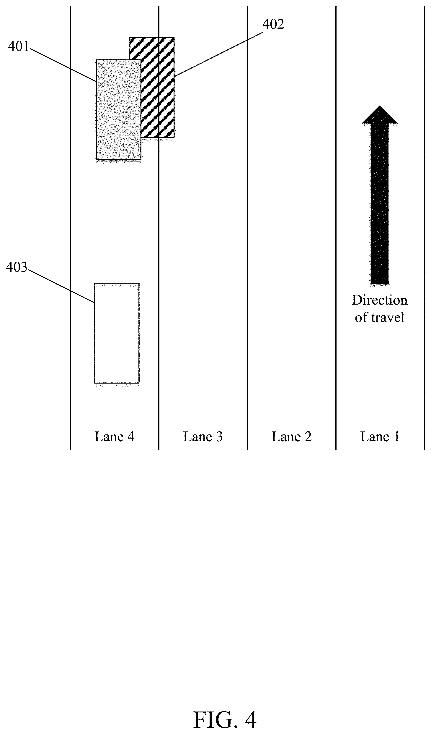
FIG. 4 illustrates a corrected position, according to an exemplary embodiment of the present disclosure.
DETAILED DESCRIPTION OF EMBODIMENTS
Further features and advantages of the invention, as well as the structure and operation of various embodiments of the invention, are described in detail below with reference to the accompanying FIGS. 1-4. Although the invention is described in the context of a system, any system or method may be implemented.
In an exemplary embodiment of the present disclosure, the system may utilize pieces of hardware including a plurality of cameras installed on a vehicle, a database, and an on-board computer, to iteratively update the vehicle's location and position relative to the lane of traffic in which it is traveling.
In an embodiment, the plurality of cameras may be installed on the vehicle and their positions and view angles are predetermined relative to the rest of the vehicle on which it is installed. In another embodiment, the plurality of cameras comprises three cameras: a first camera, a second camera, and a third camera. In one embodiment, all three cameras are installed on the vehicle in substantially the same location on the vehicle having substantially the same viewing angle. Such an embodiment would be used to provide redundancy in the event one of the cameras failed. In another embodiment, the three cameras are installed on the vehicle at different locations with different viewing angles. Such an embodiment is used to increase the accuracy of lane marking localization and fusion system in that the more viewing angles the system has to fuse location data, the greater the accuracy will be. As contemplated herein, the plurality of cameras may be installed such that they are permanently, semi-permanently, or temporarily attached to the vehicle. For example, one or more of the plurality of camera may be installed onto the vehicle such that it is integrated into the vehicle. In such an example, the camera may be installed such that it is permanently installed on the vehicle. In another example, one or more of the plurality of cameras is installed on the vehicle such that it is easily removable from the vehicle, thereby allowing the user to remove and reinstall it on another vehicle. Further, the plurality of cameras need not be dedicated to the use of the present disclosure. For example, one or more of the plurality of cameras may be embodied by cellular telephones having a built-in camera. In such an embodiment, the on-board computer may be configured to communicatively connect to the cellular telephone and receive imaging data therefrom.
In another embodiment of the present disclosure, the plurality of cameras may have different focus points and different aperture sizes. In such an embodiment, for example, the first camera may have a focus point close to the front of the vehicle such that the first camera will have the most accurate information close to the vehicle. Further in such an embodiment, the third camera may have a focus point far from the front of the vehicle in the direction of travel. In such an embodiment, the third camera will have the greatest accuracy capturing images far off into the distance. In another embodiment, the second camera may have a large aperture to allow the camera to more sensitive in low light conditions. In another embodiment, one of the plurality of cameras may be configured to capture a spectrum of light different than what is visible to the human eye. For example, one of the cameras may be configured to capture infrared light while another may be configured to capture ultraviolet light. As contemplated herein, a camera is any device that is capable of capturing location information of the environment in which the vehicle is traveling.
In an embodiment, the on-board computer may be permanently installed into the vehicle. In such an embodiment, the computer may be dedicated for use with the present disclosure.
In an embodiment, the computer fetches data from the camera and generates a response map. The on-board computer fetches data from the database to create a lane map. The on-board computer compares the response map against the lane map to determine a score. If the score is below a predetermined threshold, the on-board computer updates the vehicle position. In an embodiment, the system may output the updated location information to another on-board system. Such a system may be an automated self-driving system that steers the vehicles. In another embodiment, such a system may also be an ADAS.
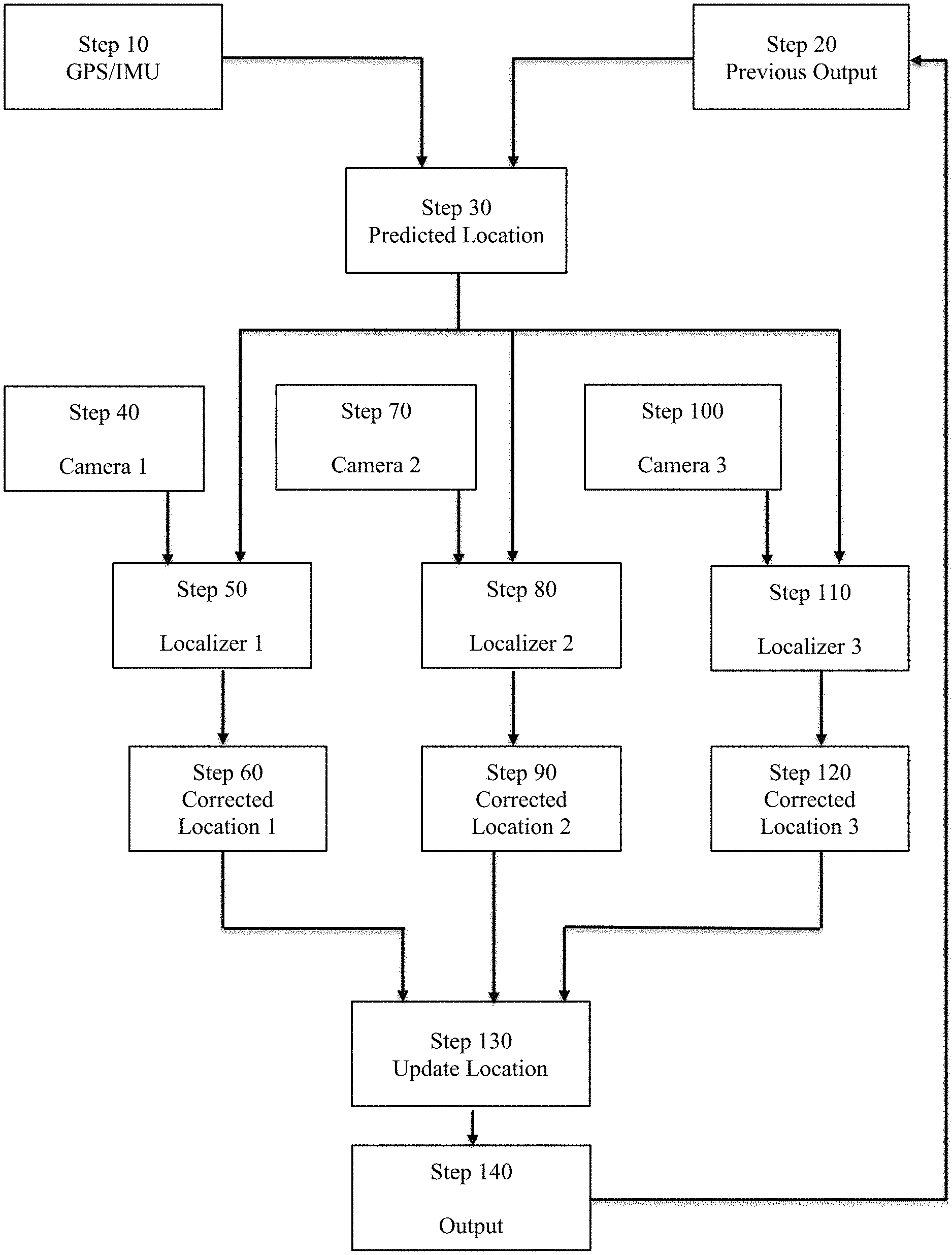
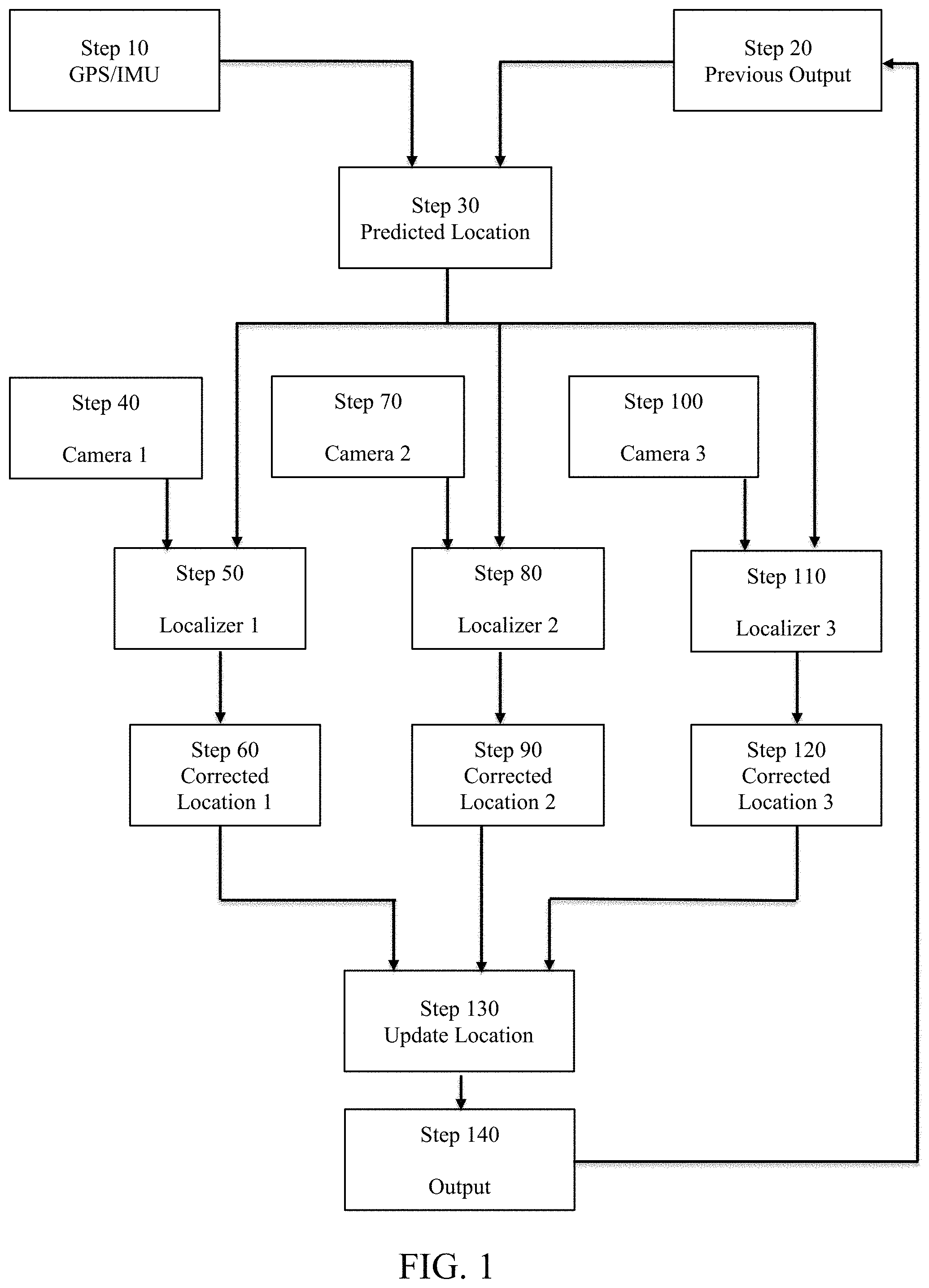
FIG. 1 illustrates an exemplary flowchart describing the steps in a system for lane marking localization and fusion according to an exemplary embodiment of the invention. In an exemplary embodiment of the present disclosure and with reference to FIG. 1, at step 10, the system fetches GPS and/or IMU location information. In an exemplary embodiment of the present disclosure, the system is utilized on a vehicle. The system may use an on-board GPS device to fetch the vehicle's location on the planet. In another embodiment, the system uses an on-board IMU in conjunction with an on-board GPS device to estimate the vehicle's location, speed, and velocity. In another embodiment, the GPS information comprises the latitude and/or longitude position of the vehicle. In another embodiment, the GPS information comprises the vehicle's yaw angle. In another embodiment, the GPS/IMU signal also comprises a time stamp.
In another exemplary embodiment of the present disclosure and with reference to FIG. 1, at step 20, the system fetches the vehicle's previous determined location.
In another exemplary embodiment of the present disclosure and with reference to FIG. 1, at step 30, the system generates a predicted location. In one embodiment, the system uses the GPS/IMU location information to predict the vehicle's location. In another embodiment, the system uses the GPS/IMU information in conjunction with the vehicle's previous location as supplied by the system to generate a predicted location. Additionally, the predicted location comprises information pertaining to the vehicle's location relative to the lane in which it is traveling. Additionally, the system may use the vehicle's pervious location in conjunction with the fetched average speed and time difference from the previous output to estimate the vehicle's current location within a roadway.
In another exemplary embodiment of the present disclosure and with reference to FIG. 1, at step 40, the system captures information from a first camera. In one embodiment, the first camera is installed on the vehicle. In another embodiment, the first camera may be temporarily affixed to the vehicle such that it may be easily installed and removed by a user. In an embodiment, the first camera may be installed such that it points in the direction of travel, i.e., towards the front of the vehicle. In another embodiment, the first camera may be installed such that it points in a direction other than the direction of travel, i.e., towards the rear or a side of the vehicle. In another embodiment, the first camera comprises a video camera gathering video at a predetermined frame rate. In an embodiment, the first camera comprises a video camera with frame rate of at least 10 frames per second. In another embodiment, the first camera comprises a photographic camera capturing images at a predetermined rate. In an embodiment, the first camera comprises a photographic camera capturing images at rate of at least 10 frames per second.
In another exemplary embodiment of the present disclosure and with reference to FIG. 1, at step 50, the system uses a first localizer to predict the vehicle's location. In an embodiment, the system generates a first region map based on location information stored in a database. Such location information may comprise information previously gathered using GPS, radar, photographic, videographic, and/or light detection and ranging ("LIDAR") technologies. In an embodiment, the system uses the vehicle's predicted location to generate the first region map. In such an embodiment, the system takes the vehicle's predicted location based on the GPS/IMU and/or the previous output to predict the location, speed, and direction of travel of the vehicle. In another embodiment, the system generates the first region map by defining structures that are predicted to be within the region map as defined by the vehicle's predicted location. In one embodiment, the structures defined within the region map include those pertaining to lanes of travel on which the vehicle is traveling. For example, the structures defined include lines painted on the roadway and reflectors installed upon the roadway. In another embodiment, the structures defined within the region map include those observable by the system and include buildings, street signs, street lights, bridges, as well as reflectors and lines painted on the roadway. In another embodiment, the structures defined within the region map include other permanent or semi-permanent structures including trees and other landscaping objects.
In another exemplary embodiment of the present disclosure and with continued reference to FIG. 1, at step 50, the system generates a first response map based on the information gathered by the first camera. The response map comprises information pertaining to the same structures as defined in the first region map. In another embodiment, the system compares the first region map with the first response map and calculates a confidence score.
In another exemplary embodiment of the present disclosure and with reference to FIG. 1, at step 60, the system generates a first corrected vehicle location based on the confidence score calculated by the first localizer. In an embodiment, the first corrected vehicle location is the same as the predicted location if the confidence score is 100%. In another embodiment, the system generates a first corrected location if the calculated confidence score is below a predetermined threshold. In such an embodiment, the system generates the first corrected location based on the vehicle's predicted location and a comparison of the first region map with the first response map.
In another exemplary embodiment of the present disclosure and with reference to FIG. 1, at step 70, the system captures information from a second camera. In one embodiment, the second camera is installed on the vehicle. In another embodiment, the second camera may be installed such that it points in the direction of travel, i.e., towards the front of the vehicle. In another embodiment, the second camera may be installed such that it points in a direction other than the direction of travel, i.e., towards the rear or a side of the vehicle. In another embodiment, the second camera comprises a video camera gathering video at a predetermined frame rate. In an embodiment, the second camera comprises a video camera with frame rate of at least 10 frames per second. In another embodiment, the second camera comprises a photographic camera capturing images at a predetermined rate. In an embodiment, the second camera comprises a photographic camera capturing images at rate of at least 10 frames per second.
In another exemplary embodiment of the present disclosure and with reference to FIG. 1, at step 80, the system uses a second localizer to predict the vehicle's location. In an embodiment, the system generates a second region map based on location information stored in a database. Such location information may comprise information previously gathered using GPS, radar, photographic, videographic, and/or LIDAR technologies. In an embodiment, the system uses the vehicle's predicted location to generate the second region map. In such an embodiment, the system takes the vehicle's predicted location based on the GPS/IMU and/or the previous output to predict the location, speed, and direction of travel of the vehicle. In another embodiment, the system generates the second region map by defining structures that are predicted to be within the region map as defined by the vehicle's predicted location. In one embodiment, the structures defined within the region map include those pertaining to lanes of travel on which the vehicle is traveling. For example, the structures defined include lines painted on the roadway and reflectors installed upon the roadway. In another embodiment, the structures defined within the region map include those observable by the system and include buildings, street signs, street lights, bridges, as well as reflectors and lines painted on the roadway. In another embodiment, the structures defined within the region map include other permanent or semi-permanent structures including trees and other landscaping objects.
In another exemplary embodiment of the present disclosure and with continued reference to FIG. 1, at step 80, the system generates a second response map based on the information gathered by the second camera. The second response map comprises information pertaining to the same structures as defined in the second region map. In another embodiment, the system compares the second region map with the second response map and calculates a confidence score.
In another exemplary embodiment of the present disclosure and with reference to FIG. 1, at step 90, the system generates a second corrected vehicle location based on the confidence score calculated by the second localizer. In an embodiment, the second corrected vehicle location is the same as the predicted location if the confidence score is 100%. In another embodiment, the system generates the second corrected location if the calculated confidence score is below a predetermined threshold. In such an embodiment, the system generates the second corrected location based on the vehicle's predicted location and a comparison of the second region map with the second response map.
In another exemplary embodiment of the present disclosure and with reference to FIG. 1, at step 100, the system captures information from a third camera. In one embodiment, the third camera is installed on the vehicle. In an embodiment, the third camera may be installed such that it points in the direction of travel, i.e., towards the front of the vehicle. In another embodiment, the third camera may be installed such that it points in a direction other than the direction of travel, i.e., towards the rear or a side of the vehicle. In another embodiment, the third camera comprises a video camera gathering video at a predetermined frame rate. In an embodiment, the third camera comprises a video camera with frame rate of at least 10 frames per second. In another embodiment, the third camera comprises a photographic camera capturing images at a predetermined rate. In an embodiment, the third camera comprises a photographic camera capturing images at rate of at least 10 frames per second.
In another exemplary embodiment of the present disclosure and with reference to FIG. 1, at step 110, the system uses a third localizer to predict the vehicle's location. In an embodiment, the system generates a third region map based on location information stored in a database. Such location information may comprise information previously gathered using GPS, radar, photographic, videographic, and/or LIDAR technologies. In an embodiment, the system uses the vehicle's predicted location to generate the third region map. In such an embodiment, the system takes the vehicle's predicted location based on the GPS/IMU and/or the previous output to predict the location, speed, and direction of travel of the vehicle. In another embodiment, the system generates the third region map by defining structures that are predicted to be within the region map as defined by the vehicle's predicted location. In one embodiment, the structures defined within the region map include those pertaining to lanes of travel on which the vehicle is traveling. For example, the structures defined include lines painted on the roadway and reflectors installed upon the roadway. In another embodiment, the structures defined within the region map include those observable by the system and include buildings, street signs, street lights, bridges, as well as reflectors and lines painted on the roadway. In another embodiment, the structures defined within the region map include other permanent or semi-permanent structures including trees and other landscaping objects.
In another exemplary embodiment of the present disclosure and with continued reference to FIG. 1, at step 110, the system generates a third response map based on the information gathered by the third camera. The third response map comprises information pertaining to the same structures as defined in the third region map. In another embodiment, the system compares the third region map with the third response map and calculates a confidence score.
In another exemplary embodiment of the present disclosure and with reference to FIG. 1, at step 120, the system generates a third corrected vehicle location based on the confidence score calculated by the third localizer. In an embodiment, the third corrected vehicle location is the same as the predicted location if the confidence score is 100%. In another embodiment, the system generates the third corrected location if the calculated confidence score is below a predetermined threshold. In such an embodiment, the system generates the third corrected location based on the vehicle's predicted location and a comparison of the third region map with the third response map.
In another exemplary embodiment of the present disclosure and with reference to FIG. 1, at step 130, the system updates the location of the vehicle. In an embodiment, the system uses the first, second, and third corrected locations to determine the most accurate position. In another embodiment, the system also utilizes the confidence scores of each corrected location to determine the most accurate vehicle position.
In another exemplary embodiment of the present disclosure and with reference to FIG. 1, at step 140, the system outputs on the updated location. In one embodiment, the system outputs the updated location to another system on the vehicle. For example, the system may output the updated location to a self-driving system piloting the vehicle. In another embodiment, the system outputs the updated location to an ADAS system. In another embodiment, the system outputs the updated location to the previous location, as described in FIG. 1, step 20.
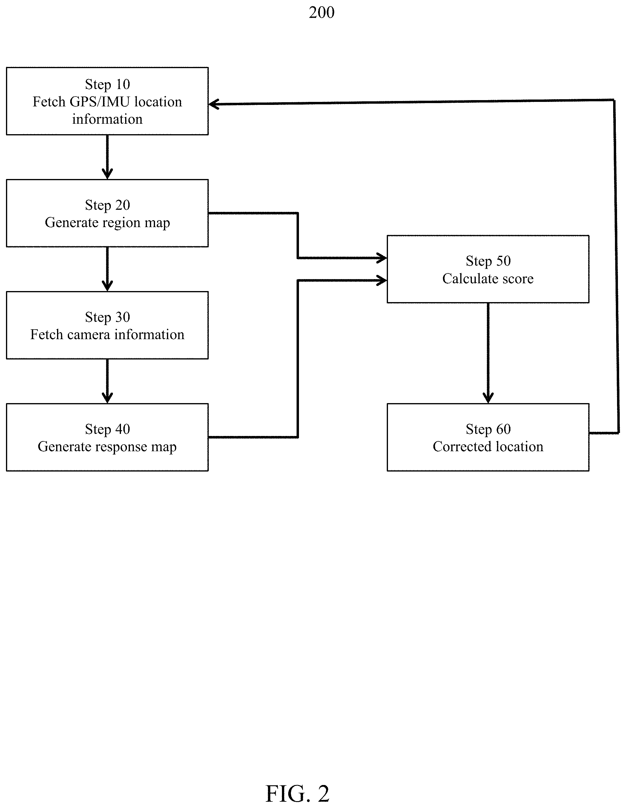
FIG. 2 illustrates a method 200 for determining a vehicle's position within a lane, according to an exemplary embodiment of the disclosure. Further, the steps described in FIG. 2 may be undertaken by a system for lane marking localization and fusion as described in FIG. 1, at steps 50, 80, and 110. At step 210, a computer fetches GPS and/or IMU location information from an GPS device and/or an IMU device. The method described herein may further utilize the vehicle's previously determined location. At step 220, the computer generates a region map comprising previously-gathered information relating to the environment in which the vehicle is traveling. For example, the region map comprises information previously gathered by a collection vehicle using radar, LIDAR, GPS, and/or cameras. Such information pertained to the collection vehicle's location on a specific roadway relative to other roadways in the area, lane-specific information relative to the lane in which the collection vehicle is traveling, and information relating to the collection vehicle's speed, direction of travel, and/or velocity relative to the location information. In one embodiment, the computer generates the region map. In another embodiment, the computer receives the region map from a database.
At step 230, the system utilizes a camera installed on the vehicle. In one embodiment, the camera is installed on the vehicle having a predetermined viewing angle and orientation. For example, the camera is installed on the roof of the vehicle, centered on the vehicle's centerline, and pointing in the direction of travel, i.e., forward. The camera captures an image of the region in front of the vehicle. In another embodiment, the camera may capture video and/or photographic images at a predetermined frame rate. In another embodiment, the camera captures infrared and/or ultraviolet light. In one embodiment, the camera captures images at a predetermined rate. In another example, the camera captures images at a rate of at least 10 images per second.
At step 240, the system generates a response map based on information fetched from the camera. The response map may be generated in real-time or in near real-time. The response map may be generated on a predetermined interval, for example, 20 times per second. In one embodiment, the system uses an image fetched from the camera and identifies lane markers within the lanes of vehicle travel depicted in the image. The camera may identify other aspects of the roadway including, but not limited to, bridges, signs, barriers, street lights, and buildings. In one embodiment, the computer comprises computer-executable code configured to detect permanent and/or semi-permanent structures within a two-dimensional image. In such an embodiment, the computer analyzes the image captured from the camera and identifies lane indicators such as painted lines and reflectors. The computer may also identify other structures such as bridges, signs, barriers, street lights, and buildings. The computer may generate a response map on a predetermined interval. In one embodiment, the computer generates a response map at least ten times per second.
At step 250, the system generates the vehicle's predicted location and calculates a confidence score for determining the vehicle's lateral position within a lane. For example, the system determines the predicted location by comparing the region map against the response map. In such an embodiment, the system samples various points within the region map identifying lanes of vehicle travel. The system samples the response map and identifies lanes of travel depicted therein. The system then compares this sampled region map to the response map and generates the vehicle's predicted location based on the differences in the perspectives of the region and response maps. In such an embodiment, the system takes the GPS/IMU information, the region map, and the response map as arguments in calculating the vehicle's predicted location. For example, if the region map is substantially the same as the response map but skewed to the left, the system's comparison recognizes the vehicle's actual position must be to the right of the GPS location. The system generates a predicted vehicle location based those differences.
In another embodiment, at step 250, the system calculates a confidence score. Additionally, the system may generate the vehicle's predicted location. In one embodiment, for example, where the region map and the response map are identical, the system generates a confidence score of 1.000. In such an example, the environment data was gathered using a collection vehicle that was located at the same physical location with the same orientation of that of the system's vehicle. The confidence score reflects the system's confidence in the vehicle's predicted position compared to its position according to the region map, relative to the vehicle's lateral position within a lane. For example, a score of 1.000 correlates to a confidence of 100% and a score of 0.000 correlates to a confidence of 0%.
At step 260, the system outputs a predicted location. In one embodiment, the system may output the predicted location to an automated self-driving system. In another embodiment, the system may output the predicted location to an ADAS. In another embodiment, the system may output a corrected location if the confidence score is below a predetermined threshold. For example, the score threshold is set at 0.900. If the system generates a confidence score of anything less than 0.900, for example, a score of 0.85, the system generates a corrected location based on the comparison of the sampled region map and the response map. In an embodiment, the mathematical variance may be used as a confidence score. Further, if the system generates a confidence score of, for example, 0.950, the system outputs the vehicle's position as determined by the GPS/IMU information. In another embodiment, the system outputs the corrected location to an ADAS and/or an automated self-driving system. In another embodiment, the mathematical variance is used as the confidence score. Additionally, the system may reinput the vehicle's predicted location to be used in a subsequent iteration of the recited method, i.e., the result may be used in step 210.
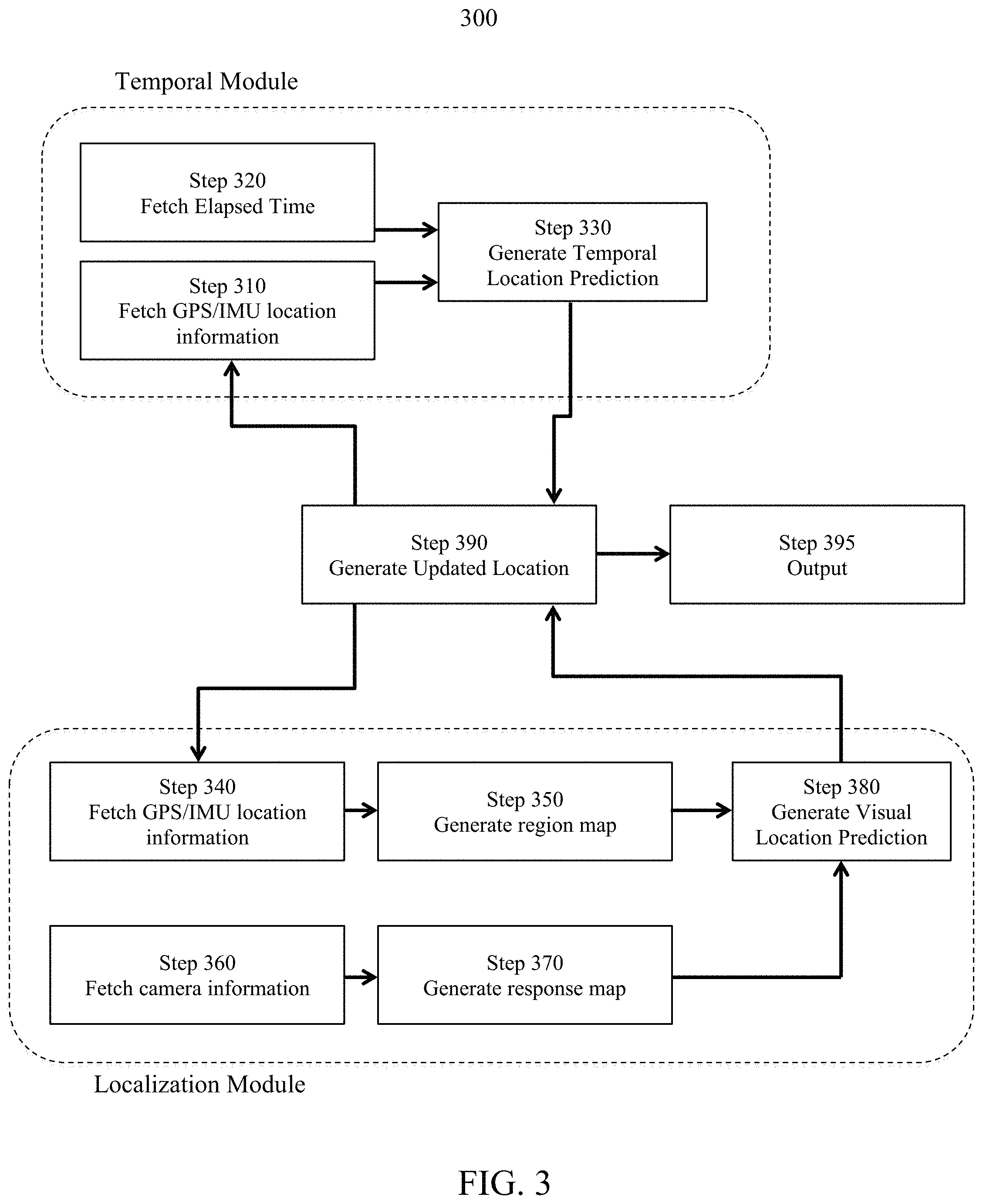
In another exemplary embodiment of the present disclosure and with reference to FIG. 3, the system and method for Lane Marking Localization and Fusion comprises a Temporal Module and a Localization Module to iteratively determine a vehicle's location.
The Temporal Module utilizes the vehicle's previously determined position, in combination with the vehicle's speed and direction to predict the vehicle's instantaneous location. The Localization Module utilizes visual information gathered from a plurality of cameras to predict the vehicle's location. The steps in the Localization Module, steps 340 through 380, are performed for each camera incorporated into the system. For example, in a system comprising three separate cameras, the present disclosure may comprise three separate Localization Modules performing the recited steps. Any number of cameras may be utilized without departing from the embodiments contemplated herein.
In the Temporal Module, at step 310, the vehicle's location is fetched from a GPS and/or an IMU device. At step 320, the elapsed time from between the vehicle's previous determined location and the instant determination is fetched. At step 330, the vehicle's instantaneous location is predicted. For example, if the vehicle had an average speed of 50 miles per hour (73.33 ft/sec) in a given direction and only 0.10 seconds have elapsed since the vehicle's position was last determined, the result of the Temporal Module, as performed in step 330, would be that the vehicle's instantaneous location is 7.333 ft further in the direction of travel, as compared to the vehicle's previous location.
In the Localization Module, at step 340, the vehicle's approximate location is fetched from a GPS and/or an IMU device. With the vehicle's GPS/IMU location, a region map is generated in step 350. At step 360, visual information is fetched from a camera and, in step 370, a response map in generated. At step 380, the Localization Module compares the region map against the response map to predict the vehicle's location. Additionally, at step 380, the system may generate a confidence score.
At step 390, the vehicle's instantaneous location is updated vis-a-vis the vehicle's location retrieved from a GPS and/or IMU device in steps 310 and/or 340. The system fuses the results of the Temporal Module, as obtained in step 330, and the results of the Localization Module, as obtained in step 380, to predict the vehicle's location. This prediction may then be used to predict the vehicle's location in the next iteration of the recited method, that is, used in steps 310 and 340. At step 395, the system may output the results of the vehicle's location obtained in step 390 to another system, such as an ADAS.
FIG. 3A illustrates an image taken by a single camera 120. Here, the camera 120 is facing the direction of travel. In other embodiments of the disclosure, the camera is positioned such that the view captured is not the direction of travel, e.g., facing behind the vehicle or to either side. In other embodiments of the disclosure, a plurality of cameras may be used. As disclosed herein, the camera may be installed anywhere on the vehicle having any orientation that allows the camera to view the vehicle's environment. When the camera is installed on the vehicle, the system may be updated as to the camera's positioning relative to the rest of the vehicle and the direction of travel. The system 100 analyzes the image taken by the camera and creates a response map by detecting lane markers such as solid lines 301, striped lines 303, and reflectors 302. In one embodiment, the camera may be permanently installed on the vehicle. For example, the camera may be integrated into the vehicle's rearview mirror or a bumper. In another embodiment, the camera may be temporarily installed on the vehicle. In another embodiment, the camera utilized may be included in a mobile device such as a cell phone or tablet. In such an embodiment, the mobile device may be temporarily installed on the vehicle and easily removed by a user.
FIG. 3B illustrates an exemplary response map according to an embodiment of the disclosure. The response map reflects lane markings as recognized by the system. For example, the response map is a binary map indicating lane markings 311 shown as black lines. In such an embodiment, the system analyzes the location information for lane indicators. When the system identifies a lane indicator, it plots a point on the response map (depicted as a black dot against a white background). Everything other than the relevant lane markings 311 are shown as white space 312. The system plots a plurality of lane indicators on the response map, culminating as lane markers 311. The system may also use physical structures such as bridges, barriers, signs, and buildings to determine lane markings.
In one embodiment, the computer 160 comprises computer-executable, non-transient code configured to detect certain elements with an image. For example, the computer 160 recognizes lane markings within a roadway including painted solid lines 301, painted striped lines 303, and reflectors 302. The system generates the response map as a series points, culminating a lane marking lines 311. The response map represents the road ahead of the vehicle, viewed from the camera 150 and perceived by the computer 160. In other embodiments, the lane markings 311 reflect other structural components such as bridges, signs, and barriers (not shown).
FIG. 3C illustrates a lane map, according to an embodiment of the present disclosure. The lane map comprises a comparison of the region map against the response map. The region map is compiled using images, GPS, radar, and/or LIDAR information. The system plots plurality of region map points 322 (shown as circles). The region map points 322 reflect lane markings as detected in the environment data 130. The response map comprises a plurality lines 321 (shown as grey lines) indicating the lane markers as viewed from the camera and perceived by the computer. The computer analyzes the differences between the region map and the response map and generates the vehicle's predicted location.
In another embodiment, the system determines a confidence score based on the differences in the lane map, which is shown in the top-left corner. For example, a perfect match overlays with 100% accuracy, resulting in a score of 1.000 (not shown). In another example, the system may determine a score of 0.74 where the overlay is a 74% match (as shown). In such an embodiment, the overlay is close, but the region map points 322 differs from the points from the response map lines 321 at some, but not all of the region map points 322. In such an embodiment, the score threshold may be 0.90, and in such an instance, the system would output a predicted vehicle location by analyzing the differences in the lane map. In another embodiment, the system may also determine other statistical parameters, such as the variance. In such an embodiment, the variance is calculated, for example, of 0.384 (as shown). For example, a logistic function may be used to calculate the variance, such as:
.times..times..times..times..times..times..times..times..times..times..fu- nction..times. ##EQU00001##
where,
x.sub.min=the minimum value
x.sub.max=the maximum value
S=the steepness
G=the growth rate
x=the matching score of the response map
m=the midpoint
FIG. 4 illustrates an updated vehicle location, according to an embodiment of the present disclosure. The predicted location 401 is determined using GPS and/or IMU locating information. Some embodiment may also consider the vehicle's previous location 403, as determined by a previous iteration of the techniques described herein. The GPS location 402 represents where the GPS perceives the vehicle to be relative to the lanes of travel. Notably, the GPS location 402 often varies greatly from the vehicle's actual location 403. Where the score is below a predetermined threshold, the system determines the predicted location 401 and outputs that location. In such an embodiment, the system recognizes which lane of traffic the vehicle is traveling. In other embodiments, the system determines the vehicle's predicted location 401 regardless of the confidence score. In other embodiments, the system may use the confidence score to determine the vehicle's predicted location 401. Although the vehicle's previous location 403 is depicted as being a single location, the techniques described herein may use any number of previously determined locations. For example, the system may utilize the 10 most recent determinations of the vehicle's previous location. Further, the system, in determining the vehicle's instantons location 401 may weight previous locations 403 differently, without departing from the embodiments contemplated herein.
Although a lane marking localization system has been shown and described, lane marking localization systems may be implemented according to other embodiments of the disclosure. For example, the system may utilize a plurality of cameras or other information gathering devices such as radar or LIDAR. Other embodiments of the disclosure may utilize a plurality of external or internal databases, on which relevant information is stored. Other embodiments also include those that output information to vehicle driving aids such as navigation and ADAS systems.
In an embodiment of the disclosure, the methodologies and techniques described herein are implemented on a special purpose computer programmed to determine lane marking and relative vehicle position. In an embodiment of the disclosure, the special-purpose computer comprises an embedded system with a dedicated processor equipped as part of a vehicle. In other embodiments, some or all of the components of the present disclosure may be integrated as part of a mobile device, for example, a cell phone or a tablet. The disclosure has been described herein using specific embodiments for the purposes of illustration only. It will be readily apparent to one of ordinary skill in the art, however, that the principles of the disclosure can be embodied in other ways. Therefore, the disclosure should not be regarded as being limited in scope to the specific embodiments disclosed herein, but instead as being fully commensurate in scope with the following claims.
* * * * *
References
D00000
D00001
D00002
D00003
D00004
D00005
D00006
M00001
M00002
XML
uspto.report is an independent third-party trademark research tool that is not affiliated, endorsed, or sponsored by the United States Patent and Trademark Office (USPTO) or any other governmental organization. The information provided by uspto.report is based on publicly available data at the time of writing and is intended for informational purposes only.
While we strive to provide accurate and up-to-date information, we do not guarantee the accuracy, completeness, reliability, or suitability of the information displayed on this site. The use of this site is at your own risk. Any reliance you place on such information is therefore strictly at your own risk.
All official trademark data, including owner information, should be verified by visiting the official USPTO website at www.uspto.gov. This site is not intended to replace professional legal advice and should not be used as a substitute for consulting with a legal professional who is knowledgeable about trademark law.