System And Method For Aerial Video Traffic Analysis
WANG; Yijie ; et al.
U.S. patent application number 15/725747 was filed with the patent office on 2019-04-11 for system and method for aerial video traffic analysis. The applicant listed for this patent is TuSimple. Invention is credited to Pengfei CHEN, Panqu WANG, Yijie WANG.
| Application Number | 20190108384 15/725747 |
| Document ID | / |
| Family ID | 65993218 |
| Filed Date | 2019-04-11 |


| United States Patent Application | 20190108384 |
| Kind Code | A1 |
| WANG; Yijie ; et al. | April 11, 2019 |
SYSTEM AND METHOD FOR AERIAL VIDEO TRAFFIC ANALYSIS
Abstract
A system and method for aerial video traffic analysis are disclosed. A particular embodiment is configured to: receive a captured video image sequence from an unmanned aerial vehicle (UAV); clip the video image sequence by removing unnecessary images; stabilize the video image sequence by choosing a reference image and adjusting other images to the reference image; extract a background image of the video image sequence for vehicle segmentation; perform vehicle segmentation to identify vehicles in the video image sequence on a pixel by pixel basis; determine a centroid, heading, and rectangular shape of each identified vehicle; perform vehicle tracking to detect a same identified vehicle in multiple image frames of the video image sequence; and produce output and visualization of the video image sequence including a combination of the background image and the images of each identified vehicle.
| Inventors: | WANG; Yijie; (San Diego, CA) ; WANG; Panqu; (San Diego, CA) ; CHEN; Pengfei; (San Diego, CA) | ||||||||||
| Applicant: |
|
||||||||||
|---|---|---|---|---|---|---|---|---|---|---|---|
| Family ID: | 65993218 | ||||||||||
| Appl. No.: | 15/725747 | ||||||||||
| Filed: | October 5, 2017 |
| Current U.S. Class: | 1/1 |
| Current CPC Class: | G06T 7/194 20170101; B64D 47/08 20130101; G06K 9/4652 20130101; G06K 9/209 20130101; G06K 9/3241 20130101; G06T 2207/20224 20130101; G08G 1/0175 20130101; G06K 2209/21 20130101; G06K 9/6256 20130101; G06T 7/11 20170101; G06T 7/254 20170101; G06T 2207/20084 20130101; G06T 2207/10032 20130101; G06T 2207/30236 20130101; G08G 1/0129 20130101; G06K 9/00765 20130101; B64C 39/024 20130101; G06T 2207/20081 20130101; G06K 9/0063 20130101; B64C 2201/123 20130101; G08G 1/012 20130101 |
| International Class: | G06K 9/00 20060101 G06K009/00; G06K 9/20 20060101 G06K009/20; G06K 9/62 20060101 G06K009/62; B64C 39/02 20060101 B64C039/02; B64D 47/08 20060101 B64D047/08 |
Claims
1. A system comprising: an unmanned aerial vehicle (UAV), equipped with a camera, deployed at an elevated position at a monitored location, the UAV configured to capture a video image sequence of the monitored location for a pre-determined period of time using the UAV camera; a data processor; and an image processing module, executable by the data processor, the image processing module being configured to: receive the captured video image sequence from the UAV; clip the video image sequence by removing unnecessary images; stabilize the video image sequence by choosing a reference image and adjusting other images to the reference image; extract a background image of the video image sequence for vehicle segmentation; perform vehicle segmentation to identify vehicles in the video image sequence on a pixel by pixel basis; determine a centroid, heading, and rectangular shape of each identified vehicle; perform vehicle tracking to detect a same identified vehicle in multiple image frames of the video image sequence; and produce output and visualization of the video image sequence including a combination of the background image and the images of each identified vehicle.
2. The system of claim 1 wherein the image processing module being configured to extract a background image of the video image sequence by inferring a dominant color value from a collection of frames sampled over time from the video image sequence.
3. The system of claim 1 wherein the image processing module being configured to perform vehicle segmentation by concatenating a video image frame with the corresponding background image.
4. The system of claim 1 wherein the image processing module being configured to perform vehicle segmentation by use of a trained neural network.
5. The system of claim 1 wherein the image processing module includes machine learnable components.
6. The system of claim 1 wherein the image processing module being configured to generate a vehicle segmentation mask.
7. The system of claim 1 wherein the image processing module being configured to generate a direction along which a variance of the shape of a vehicle as a distribution is maximized.
8. The system of claim 1 wherein the image processing module being configured to determine if a vehicle detection overlaps in two sequential image frames.
9. The system of claim 1 wherein the output and visualization includes visual bounding boxes and velocity vectors for each identified vehicle.
10. The system of claim 1 further including a human driver model configured to predict or simulate human driver behaviors.
11. A method comprising: receiving a captured video image sequence from an unmanned aerial vehicle (UAV); clipping the video image sequence by removing unnecessary images; stabilizing the video image sequence by choosing a reference image and adjusting other images to the reference image; extracting a background image of the video image sequence for vehicle segmentation; performing vehicle segmentation to identify vehicles in the video image sequence on a pixel by pixel basis; determining a centroid, heading, and rectangular shape of each identified vehicle; performing vehicle tracking to detect a same identified vehicle in multiple image frames of the video image sequence; and producing output and visualization of the video image sequence including a combination of the background image and the images of each identified vehicle.
12. The method of claim 11 including extracting the background image of the video image sequence by inferring a dominant color value from a collection of frames sampled over time from the video image sequence.
13. The method of claim 11 including performing vehicle segmentation by concatenating a video image frame with the corresponding background image.
14. The method of claim 11 including performing vehicle segmentation by use of a trained neural network.
15. The method of claim 11 including using machine learnable components.
16. The method of claim 11 including generating a vehicle segmentation mask.
17. The method of claim 11 including generating a direction along which a variance of the shape of a vehicle as a distribution is maximized.
18. The method of claim 11 including determining if a vehicle detection overlaps in two sequential image frames.
19. The method of claim 11 wherein the output and visualization includes visual bounding boxes and velocity vectors for each identified vehicle.
20. The method of claim 11 further including providing a human driver model configured to predict or simulate human driver behaviors.
Description
COPYRIGHT NOTICE
[0001] A portion of the disclosure of this patent document contains material that is subject to copyright protection. The copyright owner has no objection to the facsimile reproduction by anyone of the patent document or the patent disclosure, as it appears in the U.S. Patent and Trademark Office patent files or records, but otherwise reserves all copyright rights whatsoever. The following notice applies to the disclosure herein and to the drawings that form a part of this document: Copyright 2016-2017, TuSimple, All Rights Reserved.
TECHNICAL FIELD
[0002] This patent document pertains generally to tools (systems, apparatuses, methodologies, computer program products, etc.) for human driver modeling, trajectory generation and motion planning, vehicle control systems, autonomous driving systems, and autonomous driving simulation systems, and more particularly, but not by way of limitation, to a system and method for aerial video traffic analysis.
BACKGROUND
[0003] The control system of autonomous vehicles can sometimes be configured using a simulated human driver environment. The simulated human driver environment attempts to model the typical driving behavior of human drivers in various driving environments. However, the simulated human driver environment may be built based on the information gathered from the sensors and cameras on the autonomous vehicle or related probe vehicles. Because this information, including images from the vehicle cameras, can be subject to image occlusion and unreliable image reconstruction accuracy, the utility and effectiveness of the simulated human driver environment is degraded. Additionally, the image occlusion problem is further complicated by shadows cast by both the vehicles themselves and overhead objects such as trees, buildings, construction equipment, and the like. Classic color-based methods for shadow detection or removal do not work in this case; because of the diversity of vehicle types and colors. Because of these problems with the image data gathered for configuring the simulated human driver environment, the effectiveness of the control systems of autonomous vehicles based on the degraded simulated human driver environment can be compromised.
SUMMARY
[0004] A system and method for aerial video traffic analysis is disclosed herein. Aerial video traffic analysis includes the task of extracting traffic information, including the shape, heading, and trajectories of ground vehicles, from aerial videos captured by aerial vehicles (e.g., UAVs) positioned directly above a road surface at a desired geographical location and altitude. Aerial video is an inexpensive way to collect traffic information. Aerial video traffic analysis as disclosed herein can provide important insights into human driving behaviors in real-world traffic environments and conditions. These human driving behavior insights can be used to train a human driving behavior model, which can be used with a simulation environment for configuring autonomous vehicle control systems. In the various example embodiments disclosed herein, solutions are presented for accomplishing aerial video traffic analysis by combining classic and deep computer vision methods with a specially tailored deep learning model. The example embodiments disclosed herein can achieve pixel-level accuracy in most conditions. The example embodiments also solve another challenging problem caused by the diversity of vehicles in typical traffic environments. The example embodiments disclosed herein can recognize all types of vehicles from tiny ones like motorcycles to huge ones like car carrier trailers. The disclosed example embodiments are insensitive to the size of vehicles, making the various embodiments suitable for all types of vehicles.
BRIEF DESCRIPTION OF THE DRAWINGS
[0005] The various embodiments are illustrated by way of example, and not by way of limitation, in the figures of the accompanying drawings in which:
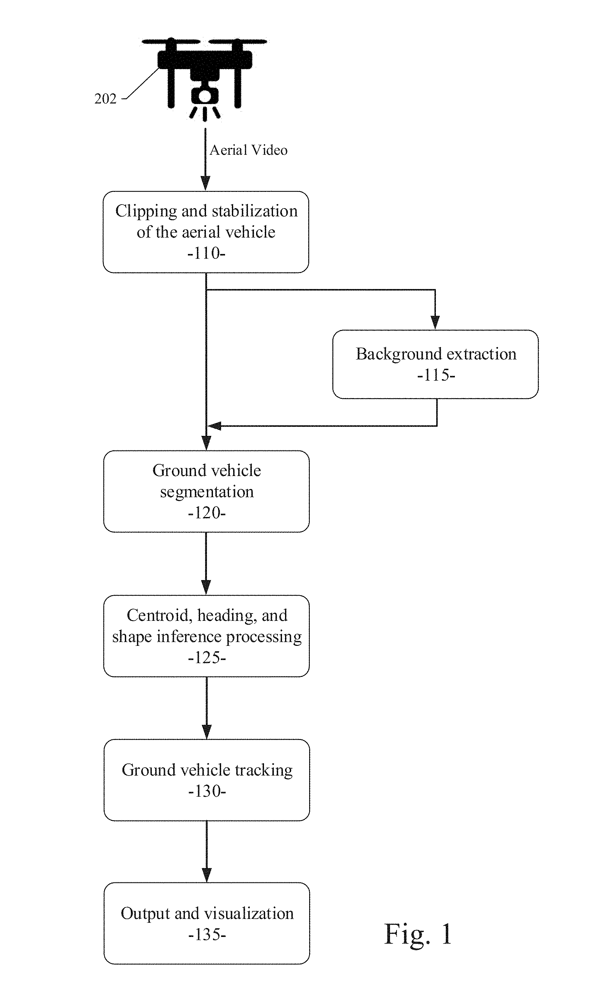
[0006] FIG. 1 is an operational flow diagram illustrating an example embodiment of a system and method for traffic data collection using unmanned aerial vehicles (UAVs);
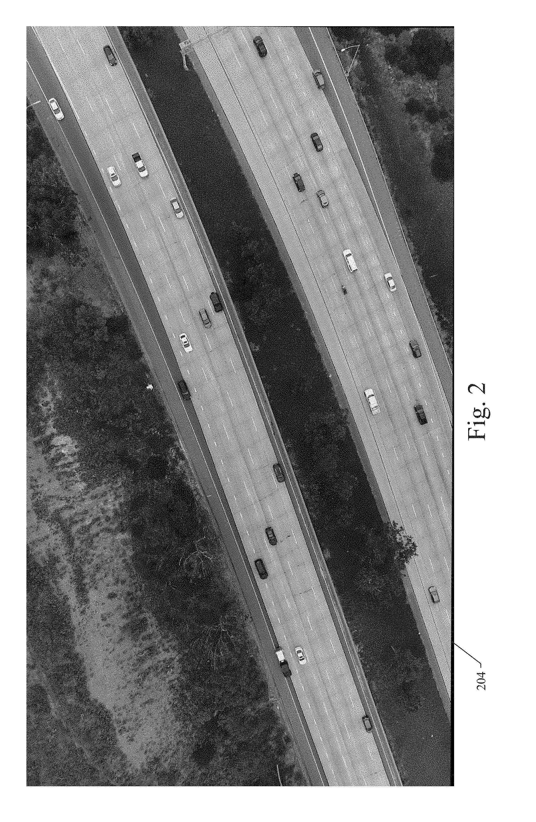
[0007] FIGS. 2 through 5 illustrate an example scenario wherein a UAV is configured with a camera and positioned at a certain location to be monitored at an elevated position to record video of the traffic activity at the location within the UAV's field of vision;
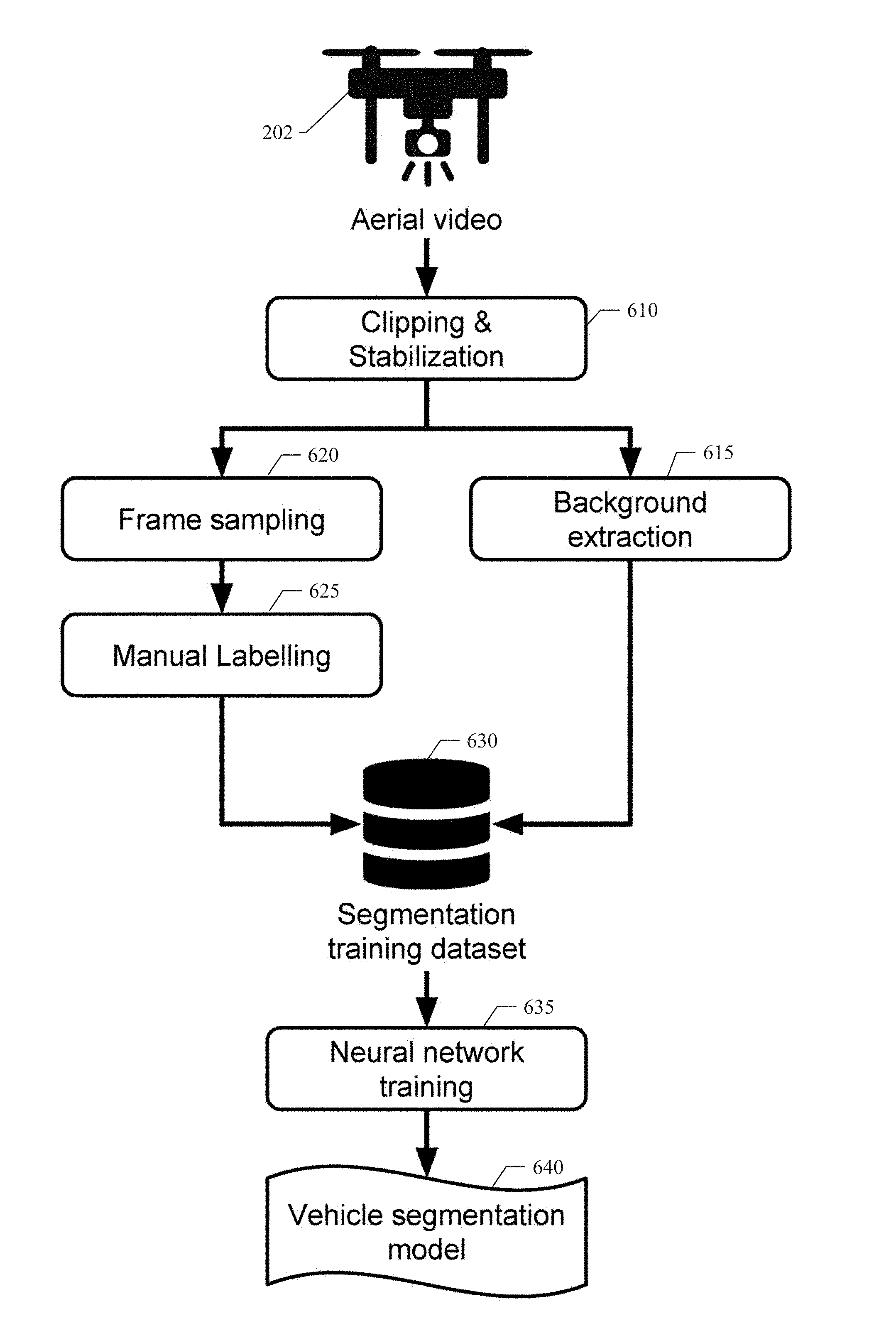
[0008] FIG. 6 is an operational flow diagram illustrating an example embodiment of a system and method for training the vehicle segmentation module of the example embodiment;
[0009] FIG. 7 illustrates the components of a human driver model system of an example embodiment;
[0010] FIG. 8 is a process flow diagram illustrating an example embodiment of a system and method for traffic data collection using UAVs; and
[0011] FIG. 9 shows a diagrammatic representation of machine in the example form of a computer system within which a set of instructions when executed may cause the machine to perform any one or more of the methodologies discussed herein.
DETAILED DESCRIPTION
[0012] In the following description, for purposes of explanation, numerous specific details are set forth in order to provide a thorough understanding of the various embodiments. It will be evident, however, to one of ordinary skill in the art that the various embodiments may be practiced without these specific details.
[0013] FIG. 1 is an operational flow diagram illustrating an example embodiment of a system and method for traffic data collection using unmanned aerial vehicles (UAVs). FIGS. 2 through 5 illustrate an example scenario of the operations shown in FIG. 1, wherein a UAV is configured with a camera and positioned at a certain location to be monitored at an elevated position to record video of the traffic activity at the location within the UAV's field of vision. Referring now to FIG. 1, a system and process for aerial video traffic analysis in an example embodiment starts with collecting aerial video image data taken by UAVs 202 that fly directly above a certain location to be monitored (e.g., expressways).
[0014] Referring now to FIG. 2, an example scenario shows a sample image captured by UAV 202 with a camera positioned at a certain location to be monitored at an elevated position to record video image data of the traffic activity at the location 204 within the UAV's field of vision. The system and method of an example embodiment provides traffic data collection using modern UAVs, which create a bird's-eye (elevated) view and provide accurate data related to traffic activity in view of the UAV. Modern UAVs 202 are able to hover or move in the sky at an elevated position to collect data related to a location with a high degree of stability regardless of weather conditions that may be inappropriate for data collection. With a high definition and stabilized camera configured on a UAV 202, data with unprecedented high quality can be collected. The data collected reflects truly realistic real-world traffic information related to the location being monitored. Additionally, the UAVs' presence does not interfere with the traffic activity the UAV is viewing, which is in contrast to any data collection method currently in practice. Further, data collection using UAVs 202 eliminates occlusion problems caused by obstructions in the camera's field of view. The lack of occlusion is crucial for the efficient and high fidelity image data processing performed after the data is collected. Finally, average inexpensive consumer UAVs 202 are sufficient to fulfill most image data collection tasks.
[0015] Referring still to FIG. 2, the UAV 202 can collect unobstructed video image data from the monitored location 204. As a result, the collected video image data can include images of roadways, traffic flows, and vehicles or other objects in the field of view over a pre-determined time period. The activity and behavior of the vehicles and objects at the location 204 can thereby be recorded and later analyzed and processed for inclusion into a human driver model. The video captured by the UAV 202 is unobstructed and thus provides a consistently clear aerial view of the monitored location 204, which provides more accurate and useful data for the human driver model. The elevated position of the UAV 202 enables better video capture, which results in better modeling and simulation. Additionally, the use of UAVs can be done with less expense and without interference with the environment as compared with the traditional systems where cameras are mounted on a probe vehicle or mounted at a fixed ground-based location.
[0016] Referring still to FIGS. 1 and 2, the UAVs 202 should ideally remain stationary when recording the video image data, but a small amount of drift is tolerable. Nevertheless, the example embodiment provides a clipping and stabilization operation (operation block 110, shown in FIG. 1) to correct for errant image data. The clipping and stabilization operation is performed on the video image data to completely remove any drift in the field of view. Clipping removes any part of the video image data in which the UAV 202 moves erratically. Stabilization aligns the background surface of all video frames to that of a chosen reference frame. In a particular embodiment, a Harris corner detector can be used to select keypoints on the reference frame. Harris corner detection is a well-known process used within computer vision systems to extract certain kinds of features and to infer the contents of the image. Next, the example embodiment can apply a pyramidal Lucas-Kanade sparse optical flow process to find keypoints corresponding to points in each video frame. In computer vision, the Lucas-Kanade method is a widely used differential method for optical flow estimation developed by Bruce D. Lucas and Takeo Kanade. By combining information from several nearby pixels, the Lucas-Kanade method can often resolve the inherent ambiguity of the optical flow equation. Additionally, the example embodiment can use a random sample consensus (RANSAC) method to solve for a perspective transformation matrix that embodies the alignment of each video frame with the reference frame. RANSAC is an iterative method to estimate parameters of a mathematical model from a set of observed data that contains outliers, when outliers are to be accorded no influence on the values of the estimates. As a result, the example embodiment can align the background surface of all video frames to that of a chosen reference frame. Stabilization of each frame is performed using the perspective transformation matrix. Segments of the video image data can be removed, if the matrix indicates that the UAV motion is larger than desired. The removal of unsuitable video segments is called clipping.
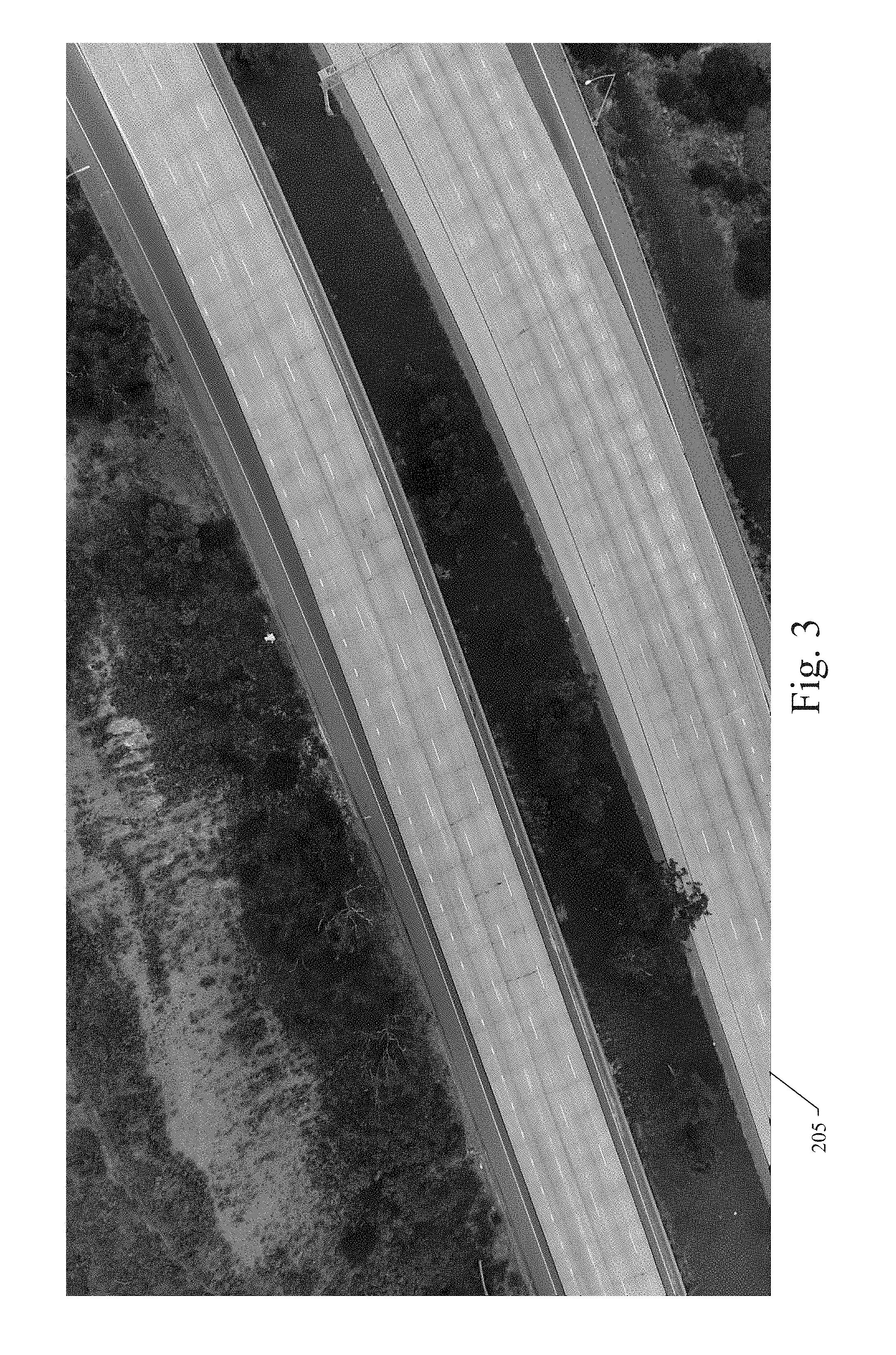
[0017] Referring now to FIG. 3, before the video image data is sent to the vehicle segmentation module 183 (shown in FIG. 7), background extraction can be performed on the video image data to generate a realistic image without any moving vehicles (operation block 115, shown in FIG. 1). In an example embodiment, background extraction can be based on a RANSAC-like process, in which, for each pixel in the field of view, the dominant color value is inferred from a collection of frames sampled over time from the video. This process tends to filter out moving objects (e.g., vehicles) from the background image; because, the pixels of the moving objects are not static over the collection of frames. In practice, this background extraction process works very well, generating background images 205 that are almost indistinguishable from real ones as shown in the example of FIG. 3.
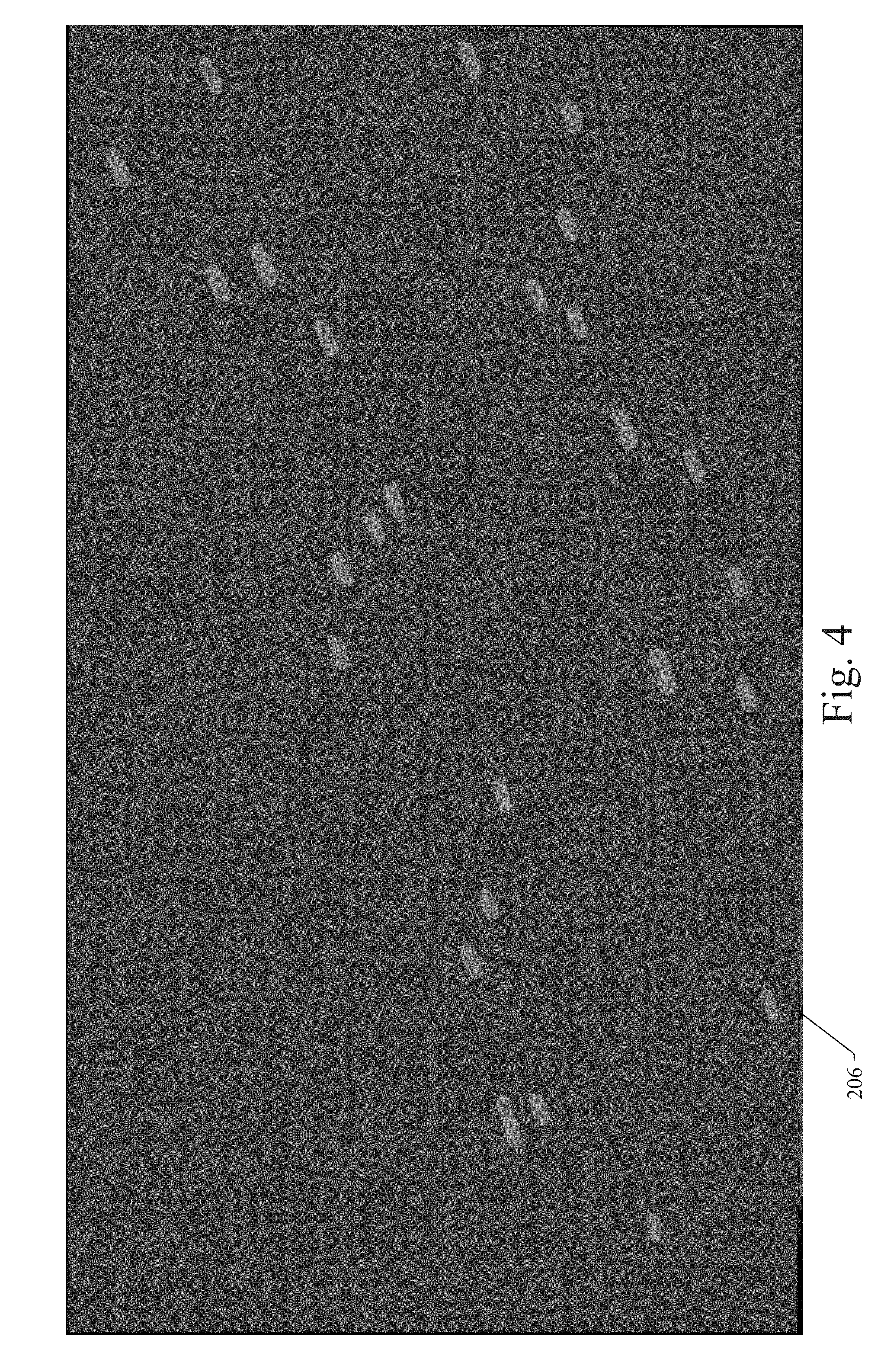
[0018] Referring now to FIG. 4, after the background is extracted from each video image as described above, the example embodiment can segment each video frame to identify the locations and shapes of the moving objects captured in the video image frames. This part of the process of an example embodiment is denoted ground vehicle segmentation (operation block 120, shown in FIG. 1). The vehicle segmentation module 183 (shown in FIG. 7) can be used for this process. The vehicle segmentation module 183 of an example embodiment can take two inputs: 1) each frame in the video image data, and 2) the corresponding background images extracted in the manner described above. For each frame in the video image data, the video image frame can be concatenated with the corresponding background image. The concatenated image data can be processed by a neural network of the vehicle segmentation module 183. In one example embodiment, a U-net architecture can be used for the neural network processing. The U-net is a convolutional network architecture for fast and precise segmentation of images. The neural network can output a binary classification of each pixel in the field of view, the binary classification representing whether the pixel is part of a vehicle or not. The training of this neural network is detailed below. The collection of binary classifications of each pixel in the field of view can be used to generate a vehicle segmentation mask, which defines the location and general or rough shape of each vehicle object identified in the video image frames within the field of view.
[0019] Referring still to FIG. 4, after the vehicle segmentation mask is generated as described above, the example embodiment can use the vehicle segmentation mask to infer the centroid, heading, and rectangular shape of each vehicle identified by the neural network (operation block 125, shown in FIG. 1). A visual representation 206 of this data is shown in the example of FIG. 4. This representation is typically a better and more useful representation as compared with a general vehicle mask, as most vehicles identified in images captured by a UAV are rectangular when viewed top-down.
[0020] As part of the process for determining the centroid, heading, and rectangular shape of each identified vehicle, the example embodiment first removes noisy points in the segmentation results produced by the vehicle segmentation module 183. Then, the remaining connected pixel components corresponding to each vehicle can be used to represent the shape of the vehicle identified in the image data. The center-of-mass of the connected components corresponding to the vehicle can be used as the centroid of the vehicle. The heading of the vehicle can be determined by solving for the eigenvectors of a centered covariance matrix corresponding to the connected components of the vehicle. As a result, the example embodiment can generate the direction along which the variance of the shape as a distribution is maximized. This direction corresponds to the heading of the vehicle associated with the shape distribution. The rectangular shape of the vehicle is inferred by taking percentiles of the shape projected along and perpendicular to the heading direction. In this manner, geometric information of each vehicle in each video frame can be extracted. Similarly, the centroid, heading, and rectangular shape of each identified vehicle can be determined as described above.
[0021] Once the geometric information of each vehicle in each video frame is extracted as described above, vehicle tracking through a collection of image frames over time can be performed (operation block 130, shown in FIG. 1). The vehicle tracking module 185 (shown in FIG. 7) can be used for this process. The vehicle tracking module 185 in the example embodiment can be applied to associate same vehicle detections in multiple image frames. In the example embodiment, a tracking method can be used, in which each vehicle detection in a single image frame can be associated with at most one vehicle detection in a previous or subsequent image frame. If image data corresponding to a vehicle detection overlaps in two sequential image frames, the vehicle tracking module 185 can infer the same vehicle detection in the multiple image frames. In this manner, the vehicle tracking module 185 can follow a same vehicle through multiple image frames and determine a velocity of the vehicle. A visible velocity vector corresponding to the velocity of each vehicle can be generated and added to the video image data. The vehicle tracking module 185, in the example embodiment, works very well, even for tiny vehicles like motorcycles, as long as the vehicle segmentation is accurate. In an alternative embodiment, each instance of the vehicles identified in the input image data 210 (shown in FIG. 7) can be tagged with a unique identifier to differentiate between the different vehicles and to enable tracking of the same vehicle in different image frames with the same identifier. This tagging process can be used, if needed, to facilitate the identification and tracking of multiple vehicles across multiple image frames.
[0022] Referring now to FIG. 5, after the centroid, heading, rectangular shape, tracking data, and velocity vector for each identified vehicle have been determined or generated as described above, an output and visualization representation 207 of the vehicle data for the identified vehicles can be generated as shown (operation block 135, shown in FIG. 1). The output and visualization representation 207 can include a combination of the background image and the images of each identified vehicle with visual bounding boxes and velocity vectors, if desired. The data corresponding to the output and visualization representation 207 can be used by the human driver model system 201, as described in more detail below, to build a model for representing typical driving behaviors in the environment imaged by the UAV.
Training of the Vehicle Segmentation Module in an Example Embodiment
[0023] FIG. 6 is an operational flow diagram illustrating an example embodiment of a system and method for training the vehicle segmentation module 183 of the example embodiment. In the example embodiment described herein, the only module in the aerial video analysis and processing pipeline that requires training is the vehicle segmentation module 183. The training of the vehicle segmentation module 183 can be performed in an offline training process as described in detail below in connection with FIG. 6.
[0024] In the offline training process of an example embodiment, in order to train the neural network of vehicle segmentation module 183 that separates vehicle objects from the background image, the offline training process includes collecting and labeling a training image dataset. In an example embodiment, a UAV is configured with a camera and positioned at a certain location to be monitored at an elevated position to record video of the traffic activity at the location within the UAV's field of vision. Referring to FIG. 6, the method for training the vehicle segmentation module 183 of the example embodiment starts with collecting aerial video image data taken by UAVs 202 that fly directly above a certain location to be monitored (e.g., expressways). The data collected by UAVs 202 reflects truly realistic real-world traffic information related to the location being monitored. The UAV 202 can collect unobstructed video image data from the monitored location 204. As a result, the collected video image data can include images of roadways, traffic flows, and vehicles or other objects in the field of view over a pre-determined time period. The activity and behavior of the vehicles and objects at the location 204 can thereby be recorded and later used to train the vehicle segmentation module 183 to accurately recognize vehicle objects in the image data.
[0025] Referring still to FIG. 6, the UAV 202 should ideally remain stationary when recording the video image data, but a small amount of drift is tolerable. Nevertheless, the example embodiment provides an offline clipping and stabilization operation (operation block 610, shown in FIG. 6) to correct for errant image data. The offline clipping and stabilization operation 610 is performed on the video image data to completely remove any drift in the field of view. Clipping removes any part of the video image data in which the UAV 202 moves erratically. Stabilization aligns the background surface of all video frames to that of a chosen reference frame. As described above for a particular embodiment, a Harris corner detector can be used to select keypoints on the reference frame. The example embodiment can apply a pyramidal Lucas-Kanade sparse optical flow process to find keypoints corresponding to points in each video frame. Additionally, the example embodiment can use a random sample consensus (RANSAC) method to solve for a perspective transformation matrix that embodies the alignment of each video frame with the reference frame. As a result, the example embodiment can align the background surface of all video frames to that of a chosen reference frame. Stabilization of each frame is performed using the perspective transformation matrix. Segments of the video image data can be removed, if the matrix indicates that the UAV motion is larger than desired. The removal of unsuitable video segments is called clipping.
[0026] Referring still to FIG. 6, an offline background extraction operation 615 can be performed on the video image data to generate a realistic image without any moving vehicles. In an example embodiment as described above, background extraction can be based on a RANSAC-like process, in which, for each pixel in the field of view, the dominant color value is inferred from a collection of frames sampled over time from the video.
[0027] Referring still to FIG. 6, after the background is extracted from each video image in operation 615 as described above, the example embodiment can store the generated data in a segmentation training dataset 630 retained in a data storage device and used for training the neural network of the vehicle segmentation module 183. Additionally, frames of the clipped and stabilized aerial video image data can be randomly sampled in operation 620 and passed to a manual image labeling process 625. The manual image labeling process 625 can include presenting the sampled image frames to human labelers or offline automated processes for manual segmentation labeling of the sampled image frames. During the manual segmentation labeling process, human labelers can draw the shapes of all vehicles in the frames. The purpose of the manual image labeling process 625 is to provide a ground truth dataset with which the vehicle segmentation module 183 can be trained. The manual segmentation labeling data generated by the manual image labeling process 625 can be stored in the segmentation training dataset 630 retained in the data storage device. Upon completion of the background extraction process 615 and the manual image labeling process 626, the sampled image frames, their corresponding background image frames, and the segmentation labelling are collected as segmentation training dataset 630 and retained for neural network training. In the example embodiment, the neural network of the vehicle segmentation module 183 can be a common neural network architecture, such as the U-net architecture described above. The neural network of the vehicle segmentation module 183 can be trained using the video image frames, the corresponding background image frames, and the manual segmentation labelling as input from the segmentation training dataset 630. Using standard neural network training procedures, the segmentation training dataset 630 can be used to configure parameters in the vehicle segmentation module 183 to cause the vehicle segmentation module 183 to accurately identify vehicle objects in one or more video image frames provided by UAVs 202. As a result, the vehicle segmentation module 183 can be trained to output accurate vehicle segmentation labelling and serve as an effective vehicle segmentation model 640, which is highly useful to support the aerial video traffic analysis system described herein.
[0028] As described above, a system of an example embodiment can provide aerial video traffic analysis. The example embodiment can include a corresponding method, which can be configured to: [0029] 1. Receive a sequence of images (e.g., video); [0030] 2. Clip the image sequence by removing unnecessary images (e.g., remove the images captured when the UAV takes off, lands, or only captures a part of a target location); [0031] 3. Stabilize the image sequence by choosing a reference image and adjusting/calibrating other images to the reference image; [0032] 4. Extract the background image of the image sequence for vehicle segmentation, extract the background image without vehicles on a pixel by pixel basis; [0033] 5. Perform object/vehicle segmentation to identify objects/vehicles in the image sequence on a pixel by pixel basis; [0034] 6. Determine the centroid, heading, and rectangular shape of each identified vehicle; [0035] 7. Perform vehicle tracking to detect the same identified vehicle in multiple image frames of the image sequence; and [0036] 8. Produce output and visualization of the image sequence including a combination of the background image and the images of each identified vehicle with visual bounding boxes and velocity vectors, if desired.
[0037] Referring now to FIG. 7, an example embodiment disclosed herein can be used in the context of a human driver model system 201 for autonomous vehicles. In one example embodiment, the human driver model system 201 can receive high definition image data and other sensor data (e.g., traffic or vehicle image data 210) from a UAV positioned above a particular roadway (e.g., monitored location) being monitored. The image data collected by the UAV reflects truly realistic, real-world traffic information related to the location being monitored. Using the standard capabilities of well-known UAV's, the traffic or vehicle image data 210 can be wirelessly (or otherwise) transferred to a data processor 171 of a standard computing system, upon which a human driver model module 175 and/or an image processing module 173 can be executed. Alternatively, the traffic or vehicle image data 210 can be stored in a memory device on the UAV and transferred later to the data processor 171. The processing performed by the human driver model module 175 of an example embodiment is described in more detail below. The traffic or vehicle image data 210 provided by the deployed UAV can be received and processed by the image processing module 173, which can also be executed by the data processor 171. As described above, the image processing module 173 can perform clipping, stabilization, background extraction, object/vehicle segmentation, vehicle centroid, heading, and shape inference processing, vehicle tracking, output and visualization generation, and other image processing functions to isolate vehicle or object presence and activity in the received images. The human driver model module 175 can use the information related to these real-world vehicle or objects to create corresponding simulations of vehicles or objects in the human driver model. Parameter values retained in a vehicle segmentation and human driver model parameter dataset 174 stored in a memory 172 can be used to configure the operation of the human driver model module 175. As described in more detail above, the elevated position of the UAV above the location being monitored and the stabilized high definition camera on the UAV provides a highly valuable and useful image and data feed for use by the human driver model module 175. As a result of the processing performed by the human driver model system 201, data corresponding to predicted or simulated driver behaviors 220 can be produced and provided to a user or other system components. In particular, the predicted or simulated driver behavior data 220 can be provided to a system component used to create a virtual world where a control system for an autonomous vehicle can be trained and improved. The virtual world is configured to be identical (as possible) to the real world where vehicles are operated by human drivers. In other words, the simulated driver behavior data is indirectly useful for configuring the control system for the autonomous vehicle. It will be apparent to those of ordinary skill in the art that the human driver model system 201 and the traffic or vehicle image data 210 described and claimed herein can be implemented, configured, processed, and used in a variety of other applications and systems as well.
[0038] A basic human driver model may be used to simulate or predict the behavior of an autonomous vehicle with a simulated driver in a simulation scenario. The basic human driver model represents a virtual world configured to be identical (as possible) to the real world where vehicles are operated by human drivers. The virtual world can be used to train and improve a control system for an autonomous vehicle. Thus, the simulation can be indirectly useful for configuring the control systems in autonomous vehicles. Such human driver models can be parameterized models, which may be configured using either real-world input or randomized variables. In one example, the basic human driver model may simulate the typical and atypical driver behaviors, such as steering or heading control, speed or throttle control, and stopping or brake control. In one example, the basic human driver model may use, for example, sensory-motor transport delay, dynamic capabilities, and preferred driving behaviors. In some implementations, the human driver model may include modeling of the transport time delay between a stimulus and the simulated driver's control response. In some implementations, this delay may represent the time necessary for the driver to sense a stimulus, process it, determine the best corrective action, and respond. The human driver model may also include a speed control model with an absolute maximum vehicle speed (e.g., the maximum speed of the vehicle, the speed a driver is not comfortable exceeding, etc.) and a cornering aggressiveness measure to reduce the speed based on the turning radius. In the example, this may replicate the tendency of drivers to slow down through a turn. In the example, once the turning radius drops below the cornering threshold in the scenario, the speed may be reduced in proportion to the tightness of the turn.
[0039] In various example embodiments, the human driver model can be configured to simulate more than the typical driving behaviors. To simulate an environment that is identical to the real world as much as possible, the human driver model needs data concerning typical driving behaviors, which represent average people, while atypical driving behaviors are equally needed. In other words, in reality, most human drivers drive vehicles in a pleasant and humble way, while other drivers drive aggressively and impatiently. Equivalently, the simulation system of the various example embodiments includes data related to the driving behaviors of impolite and impatient drivers in the virtual world. In all, the human driver model can be configured with data representing driving behaviors as varied as possible.
[0040] In some implementations, the dynamics of how a human may respond to stimuli may be included in the human driver model, which may include, for example, a metric of how aggressively the driver brakes and accelerates. In some implementations, an aggressive driver may be modeled as one who applies very high control inputs to achieve the desired vehicle speeds, while a conservative driver may use more gradual control inputs. In some implementations, this may be modelled using parameterized values, with the input being controlled to the desired value. In some implementations, by adjusting the parameterized values, the aggressiveness of the simulated driver may be increased or decreased.
[0041] Referring now to FIG. 8, a flow diagram illustrates an example embodiment of a system and method 1000 for aerial video traffic analysis. The example embodiment can be configured to: receive a captured video image sequence from an unmanned aerial vehicle (UAV) (processing block 1010); clip the video image sequence by removing unnecessary images (processing block 1020); stabilize the video image sequence by choosing a reference image and adjusting other images to the reference image (processing block 1030); extract a background image of the video image sequence for vehicle segmentation (processing block 1040); perform vehicle segmentation to identify vehicles in the video image sequence on a pixel by pixel basis (processing block 1050); determine a centroid, heading, and rectangular shape of each identified vehicle (processing block 1060); perform vehicle tracking to detect a same identified vehicle in multiple image frames of the video image sequence (processing block 1070); and produce output and visualization of the video image sequence including a combination of the background image and the images of each identified vehicle (processing block 1080).
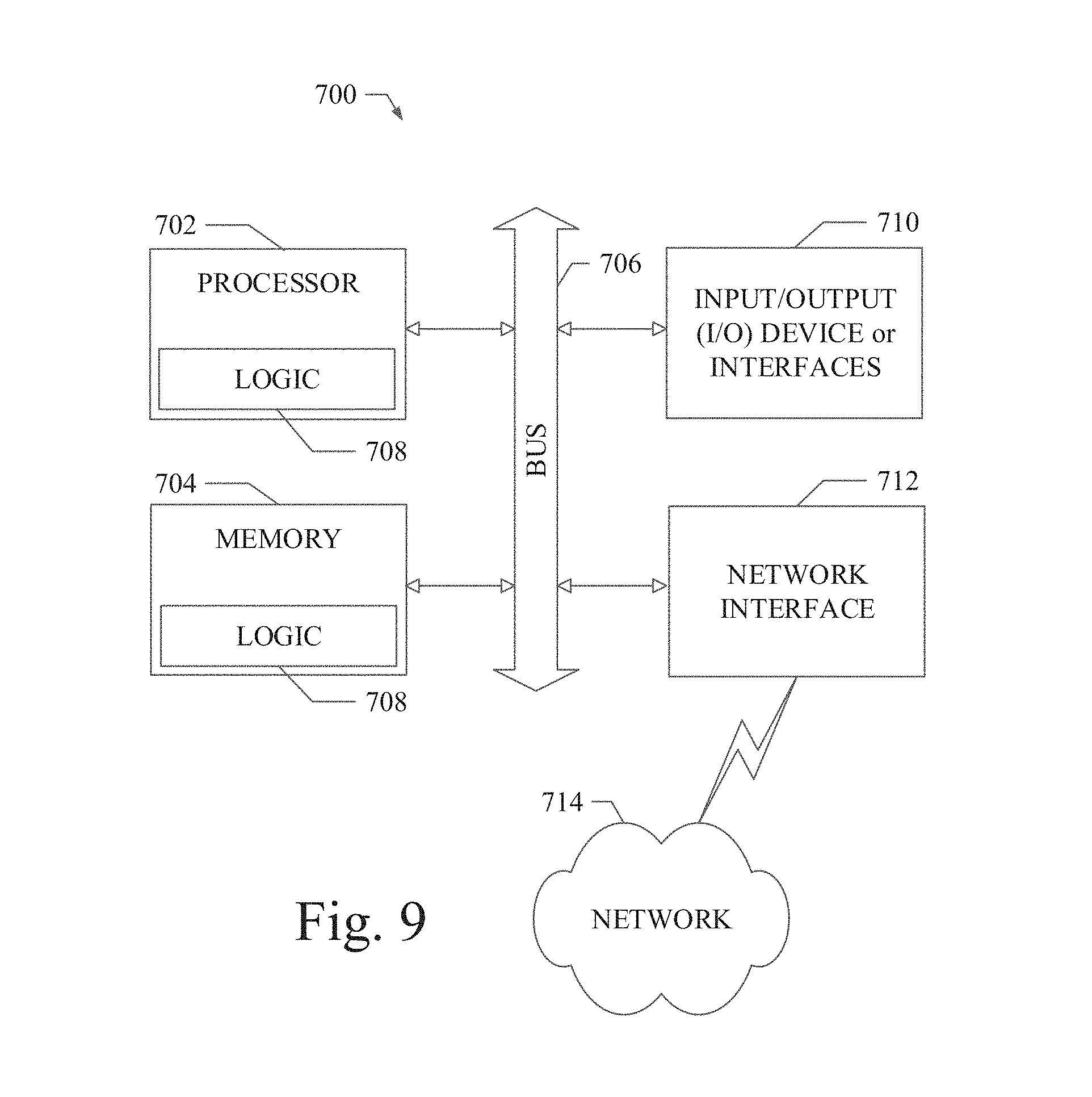
[0042] FIG. 9 shows a diagrammatic representation of a machine in the example form of a computing system 700 within which a set of instructions when executed and/or processing logic when activated may cause the machine to perform any one or more of the methodologies described and/or claimed herein. In alternative embodiments, the machine operates as a standalone device or may be connected (e.g., networked) to other machines. In a networked deployment, the machine may operate in the capacity of a server or a client machine in server-client network environment, or as a peer machine in a peer-to-peer (or distributed) network environment. The machine may be a personal computer (PC), a laptop computer, a tablet computing system, a Personal Digital Assistant (PDA), a cellular telephone, a smartphone, a web appliance, a set-top box (STB), a network router, switch or bridge, or any machine capable of executing a set of instructions (sequential or otherwise) or activating processing logic that specify actions to be taken by that machine. Further, while only a single machine is illustrated, the term "machine" can also be taken to include any collection of machines that individually or jointly execute a set (or multiple sets) of instructions or processing logic to perform any one or more of the methodologies described and/or claimed herein.
[0043] The example computing system 700 can include a data processor 702 (e.g., a System-on-a-Chip (SoC), general processing core, graphics core, and optionally other processing logic) and a memory 704, which can communicate with each other via a bus or other data transfer system 706. The mobile computing and/or communication system 700 may further include various input/output (I/O) devices and/or interfaces 710, such as a touchscreen display, an audio jack, a voice interface, and optionally a network interface 712. In an example embodiment, the network interface 712 can include one or more radio transceivers configured for compatibility with any one or more standard wireless and/or cellular protocols or access technologies (e.g., 2nd (2G), 2.5, 3rd (3G), 4th (4G) generation, and future generation radio access for cellular systems, Global System for Mobile communication (GSM), General Packet Radio Services (GPRS), Enhanced Data GSM Environment (EDGE), Wideband Code Division Multiple Access (WCDMA), LTE, CDMA2000, WLAN, Wireless Router (WR) mesh, and the like). Network interface 712 may also be configured for use with various other wired and/or wireless communication protocols, including TCP/IP, UDP, SIP, SMS, RTP, WAP, CDMA, TDMA, UMTS, UWB, WiFi, WiMax, Bluetooth.TM., IEEE 802.11x, and the like. In essence, network interface 712 may include or support virtually any wired and/or wireless communication and data processing mechanisms by which information/data may travel between a computing system 700 and another computing or communication system via network 714.
[0044] The memory 704 can represent a machine-readable medium on which is stored one or more sets of instructions, software, firmware, or other processing logic (e.g., logic 708) embodying any one or more of the methodologies or functions described and/or claimed herein. The logic 708, or a portion thereof, may also reside, completely or at least partially within the processor 702 during execution thereof by the mobile computing and/or communication system 700. As such, the memory 704 and the processor 702 may also constitute machine-readable media. The logic 708, or a portion thereof, may also be configured as processing logic or logic, at least a portion of which is partially implemented in hardware. The logic 708, or a portion thereof, may further be transmitted or received over a network 714 via the network interface 712. While the machine-readable medium of an example embodiment can be a single medium, the term "machine-readable medium" should be taken to include a single non-transitory medium or multiple non-transitory media (e.g., a centralized or distributed database, and/or associated caches and computing systems) that store the one or more sets of instructions. The term "machine-readable medium" can also be taken to include any non-transitory medium that is capable of storing, encoding or carrying a set of instructions for execution by the machine and that cause the machine to perform any one or more of the methodologies of the various embodiments, or that is capable of storing, encoding or carrying data structures utilized by or associated with such a set of instructions. The term "machine-readable medium" can accordingly be taken to include, but not be limited to, solid-state memories, optical media, and magnetic media.
[0045] The Abstract of the Disclosure is provided to allow the reader to quickly ascertain the nature of the technical disclosure. It is submitted with the understanding that it will not be used to interpret or limit the scope or meaning of the claims. In addition, in the foregoing Detailed Description, it can be seen that various features are grouped together in a single embodiment for the purpose of streamlining the disclosure. This method of disclosure is not to be interpreted as reflecting an intention that the claimed embodiments require more features than are expressly recited in each claim. Rather, as the following claims reflect, inventive subject matter lies in less than all features of a single disclosed embodiment. Thus, the following claims are hereby incorporated into the Detailed Description, with each claim standing on its own as a separate embodiment.
* * * * *
D00000
D00001
D00002
D00003
D00004
D00005
D00006
D00007
D00008
D00009
XML
uspto.report is an independent third-party trademark research tool that is not affiliated, endorsed, or sponsored by the United States Patent and Trademark Office (USPTO) or any other governmental organization. The information provided by uspto.report is based on publicly available data at the time of writing and is intended for informational purposes only.
While we strive to provide accurate and up-to-date information, we do not guarantee the accuracy, completeness, reliability, or suitability of the information displayed on this site. The use of this site is at your own risk. Any reliance you place on such information is therefore strictly at your own risk.
All official trademark data, including owner information, should be verified by visiting the official USPTO website at www.uspto.gov. This site is not intended to replace professional legal advice and should not be used as a substitute for consulting with a legal professional who is knowledgeable about trademark law.