Surgical instrument having a surface texture
Grueebler , et al. April 27, 2
U.S. patent number 10,987,119 [Application Number 15/708,630] was granted by the patent office on 2021-04-27 for surgical instrument having a surface texture. This patent grant is currently assigned to Alcon Inc.. The grantee listed for this patent is Novartis AG. Invention is credited to Reto Grueebler, Markus Hupp, Pooria Sharif Kashani.


| United States Patent | 10,987,119 |
| Grueebler , et al. | April 27, 2021 |
Surgical instrument having a surface texture
Abstract
Surgical instruments and, particularly, ophthalmic surgical instruments are disclosed. Example surgical instruments include forceps for removal of an internal limiting membrane (ILM). The example forceps may include a textured surface formed at a distal end of the forceps jaws. The textured surface may have a plurality of microposts that operate to increase a coefficient of friction between the ILM and the forceps in order to reduce a normal force, applied by the forceps, needed to engage the ILM.
| Inventors: | Grueebler; Reto (Greifensee, CH), Hupp; Markus (Zurich, CH), Kashani; Pooria Sharif (Irvine, CA) | ||||||||||
|---|---|---|---|---|---|---|---|---|---|---|---|
| Applicant: |
|
||||||||||
| Assignee: | Alcon Inc. (Fribourg,
CH) |
||||||||||
| Family ID: | 1000005512762 | ||||||||||
| Appl. No.: | 15/708,630 | ||||||||||
| Filed: | September 19, 2017 |
Prior Publication Data
| Document Identifier | Publication Date | |
|---|---|---|
| US 20180103972 A1 | Apr 19, 2018 | |
Related U.S. Patent Documents
| Application Number | Filing Date | Patent Number | Issue Date | ||
|---|---|---|---|---|---|
| 62517504 | Jun 9, 2017 | ||||
| 62409660 | Oct 18, 2016 | ||||
| Current U.S. Class: | 1/1 |
| Current CPC Class: | A61B 17/30 (20130101); A61B 17/282 (20130101); A61B 2017/00526 (20130101); A61B 2017/00982 (20130101); A61B 2017/2926 (20130101) |
| Current International Class: | A61B 17/28 (20060101); A61B 17/30 (20060101); A61B 17/29 (20060101); A61B 17/00 (20060101) |
References Cited [Referenced By]
U.S. Patent Documents
| 2795225 | June 1957 | Sovatkin et al. |
| 4671283 | June 1987 | Hoskin et al. |
| 4693246 | September 1987 | Reimels |
| 4994079 | February 1991 | Genese et al. |
| 5078716 | January 1992 | Doll |
| 5208111 | May 1993 | Decher et al. |
| 5222973 | June 1993 | Shame et al. |
| 5234458 | August 1993 | Metais |
| 5340354 | August 1994 | Anderson et al. |
| 5496330 | March 1996 | Bates et al. |
| 5601572 | February 1997 | Middleman et al. |
| 5634918 | June 1997 | Richards |
| 5700559 | December 1997 | Sheu et al. |
| 5739237 | April 1998 | Russell et al. |
| 5792145 | August 1998 | Bates et al. |
| 5810881 | September 1998 | Hoskin et al. |
| 5855586 | January 1999 | Habara et al. |
| 5919202 | July 1999 | Yoon |
| 5921998 | July 1999 | Tano et al. |
| 5972021 | October 1999 | Huttner et al. |
| 6077274 | June 2000 | Ouchi et al. |
| 6120518 | September 2000 | Mark et al. |
| 6267759 | July 2001 | Quick |
| 6340354 | January 2002 | Rambin |
| D456077 | April 2002 | Etter et al. |
| 6451037 | September 2002 | Chandrasekaran et al. |
| 6464629 | October 2002 | Boone et al. |
| 6488695 | December 2002 | Hickingbotham |
| 6575989 | June 2003 | Scheller et al. |
| 6592600 | July 2003 | Nicolo |
| 6685725 | February 2004 | Attinger et al. |
| 6730076 | May 2004 | Hickingbotham |
| 6772765 | August 2004 | Scheller et al. |
| 6920965 | July 2005 | Burgdorf et al. |
| 6995336 | February 2006 | Hunt et al. |
| 7251893 | August 2007 | Cohen et al. |
| 7335271 | February 2008 | Autumn |
| 7410606 | August 2008 | Appleby et al. |
| 7582327 | September 2009 | Qiu et al. |
| 7867230 | January 2011 | Asahara et al. |
| 7893413 | February 2011 | Appleby et al. |
| 8150506 | April 2012 | Kaushal et al. |
| 8241321 | August 2012 | Scheller et al. |
| 8425596 | April 2013 | Britton et al. |
| 8469993 | June 2013 | Rothberg et al. |
| 8579887 | November 2013 | Hanlon et al. |
| 8795196 | August 2014 | Cho et al. |
| 8821444 | September 2014 | Scheller et al. |
| 9060842 | June 2015 | Karp et al. |
| 9138346 | September 2015 | Scheller et al. |
| 9173772 | November 2015 | Scheller et al. |
| 9174184 | November 2015 | Kang et al. |
| 9204995 | December 2015 | Scheller et al. |
| 9226762 | January 2016 | Scheller et al. |
| 9247951 | February 2016 | Scheller et al. |
| 9320534 | April 2016 | Vezzu |
| 9428254 | August 2016 | Scheller et al. |
| 9586044 | March 2017 | Ross |
| 9592074 | March 2017 | Hanlon et al. |
| 9629645 | April 2017 | Scheller et al. |
| 9775943 | April 2017 | Scheller et al. |
| 9795506 | October 2017 | Scheller et al. |
| 10039565 | August 2018 | Vezzu |
| 2002/0068954 | June 2002 | Foster |
| 2003/0060812 | March 2003 | Hickingbotham |
| 2004/0020015 | February 2004 | Yokemura et al. |
| 2004/0193214 | September 2004 | Scheller |
| 2004/0260337 | December 2004 | Freed |
| 2007/0043352 | February 2007 | Garrison et al. |
| 2007/0179512 | August 2007 | Olsen et al. |
| 2007/0225785 | September 2007 | Park et al. |
| 2007/0239202 | October 2007 | Rodriguez |
| 2007/0282348 | December 2007 | Lumpkin |
| 2008/0021399 | January 2008 | Spaide |
| 2008/0058761 | March 2008 | Spaide |
| 2008/0167576 | July 2008 | Cho et al. |
| 2008/0183199 | July 2008 | Attinger |
| 2009/0030448 | January 2009 | Andre |
| 2010/0226943 | September 2010 | Brennan et al. |
| 2011/0015669 | January 2011 | Corcosteugi |
| 2011/0021965 | January 2011 | Karp et al. |
| 2011/0270221 | November 2011 | Ross |
| 2011/0282190 | November 2011 | Caffey et al. |
| 2013/0059113 | March 2013 | Hatton et al. |
| 2013/0204245 | August 2013 | Ivanisevic et al. |
| 2014/0135820 | May 2014 | Schaller et al. |
| 2014/0172010 | June 2014 | Vezzu |
| 2014/0277110 | September 2014 | Scheller |
| 2014/0379024 | December 2014 | Schaller et al. |
| 2015/0088193 | March 2015 | Scheller et al. |
| 2015/0238355 | August 2015 | Vezzu |
| 2015/0297278 | October 2015 | Scheller |
| 2016/0066940 | March 2016 | Scheller et al. |
| 2016/0074219 | March 2016 | Scheller et al. |
| 2016/0296246 | October 2016 | Schaller |
| 2017/0119419 | May 2017 | Scheller et al. |
| 2017/0165109 | June 2017 | Gunn |
| 2017/0296382 | October 2017 | Mukai |
| 2019/0000670 | January 2019 | Grueebler |
| 2825008 | Jul 2012 | CA | |||
| 10637419 | Feb 2010 | CN | |||
| 201624872 | Nov 2010 | CN | |||
| 102565057 | Jul 2012 | CN | |||
| 104837444 | Aug 2015 | CN | |||
| 104994793 | Oct 2015 | CN | |||
| 204839914 | Dec 2015 | CN | |||
| 29714735 | Oct 1997 | DE | |||
| 102009033015 | Jan 2011 | DE | |||
| 1406536 | Jan 2003 | EP | |||
| 1295580 | Mar 2003 | EP | |||
| 1511433 | Mar 2005 | EP | |||
| 1463455 | Aug 2005 | EP | |||
| 1986581 | Mar 2012 | EP | |||
| 2214590 | Aug 2016 | EP | |||
| 2086792 | May 1982 | GB | |||
| 2086792 | Aug 2018 | GB | |||
| S57110238 | Jul 1982 | JP | |||
| 2003159270 | Jun 2003 | JP | |||
| 2005529678 | Oct 2005 | JP | |||
| 2006527633 | Dec 2006 | JP | |||
| 43173 | Jan 2005 | RU | |||
| 117617 | Nov 1958 | SU | |||
| 199511629 | May 1995 | WO | |||
| 9924091 | May 1999 | WO | |||
| 2003105705 | Dec 2003 | WO | |||
| 2004020015 | Mar 2004 | WO | |||
| 2005086772 | Sep 2005 | WO | |||
| 2007103671 | Sep 2007 | WO | |||
| 2008011225 | Jan 2008 | WO | |||
| 2009067649 | May 2009 | WO | |||
| 2011097578 | Aug 2011 | WO | |||
| 201197578 | Nov 2011 | WO | |||
| 2011143388 | Nov 2011 | WO | |||
| 2012064361 | May 2012 | WO | |||
| 2014078049 | May 2014 | WO | |||
| 2014092956 | Jun 2014 | WO | |||
| WO2015124467 | May 2015 | WO | |||
| 2016063707 | Apr 2016 | WO | |||
Other References
|
Gruber, A.E., et al. "Miniaturisierte Instrumente aus Nickel-Titan Legierungen fur die minimal Invasive Therapie [Miniaturized Instruments made from Nickel-Titanium Alloys for Minimally Invasive Therapy]" Karsruhe Research vol. 32 (2000): 70-76 Published 2000. cited by applicant . Semeraro, Francesco, et al. "Current Trends about Inner Limiting Membrane Peeling in Surgery for Epiretinal Membranes." Journal of Ophthalmology. vol. 2015 (2015), 13 pages. cited by applicant . Bhisitkul, R.B., Development of Microelectromechanical Systems (MEMS) Forceps for Intraocular Surgery, C.G. Keller, Br. J. Ophthalmol, 2005; 89 pages 1586-1588. Aug. 1, 2005 (3 pages). cited by applicant . A Wafer-Based, 3-D Metal Micro-Manufacturing Technology for Ultraminiaturized Medical Devices Pamphlet, Oct. 29, 2008 (38 pages). cited by applicant . Research: Micro-Scale Surgical Tools_LIBNA, 2003 (2 pages). cited by applicant . Aoki, I, Takahashi, T., Mihara, S., Yamagata, Y., Higuchi, T., Trial Production of Medical Micro-Tool by Metal Deformation Processes Using Moulds, 344-349. Conference date Jan. 29-Feb. 2, 1995 (6 pages). cited by applicant . Bhisitkul, R.B., Development of Microelectromechanical Systems (MEMS) Forceps for Intraocular Surgery, C.G. Keller, Br. J. Ophthalmol, 2005; 89: pp. 1586-1588. cited by applicant . "Grieshaber Revolution DSP", Alcon, Vitreoretical Product Catalog, 6 pgs., 2012 Novartis 7/12 VIT12052MSA. cited by applicant . Pavoor, P., Wear Reduction of Orthopaedic Bearing Surfaces Using Polyelectrolyte Multilayer Nanocoatings, Elsevier, 2006, pp. 1527-1533. cited by applicant . PCT/EP2015/052791; International Searching Authority, International Search Report, Apr. 24, 2015, 5 pgs. cited by applicant . Prosecution History, U.S. Appl. No. 14/550,470, 42 pages, Jan. 6, 2015. (5016). cited by applicant . Rabinovich, et al, "Adhesion between Nanoscale Rough Surfaces II. Measurement and Comparison with Theory", J.Colloid & Interface Sci., Aug. 2000, 232, pp. 17-24 (DOI:10.1006/jcis.2000.7168). cited by applicant . Rabinovich, et al, "Adhesion between Nanoscale Rough Surfaces, I. Role of Asperity Geometry", J.Colloid & Interface Sci., Aug. 2000, 232, pp. 10-16 (DOI:10.1006/jcis.2000.7167). cited by applicant . United States Patent and Trademark Office, U.S. Appl. No. 61/302,064, filed Feb. 5, 2010, pp. 1-41. cited by applicant . United States Patent and Trademark Office, U.S. Appl. No. 61/389,573, filed Oct. 4, 2010, pp. 1-37. cited by applicant . Valentin-Rodriguez, et al, "Quantitative Analysis of Human Internal Limiting Membrane Extracted from Patient with Macular Holes", Langmuir, Jun. 2010, 26(15), pp. 12810-12816 (DOI: 10.102/Ia101797e). cited by applicant . Valentin-Rodriguez, C., Turning the Adhesion of Layer-by-Layer Films to the Physicochemical Properties of Inner Limiting Membranes Using Nanoparticles, Elsevier, 2011, pp. 616-624. cited by applicant . Alexander Vankov et al., Electro-adhesive Forceps for Tissue Manipulation, Department of Ophthalmology, School of Medicine, Stanford Univ. cited by applicant . Celimar Valentine-Rodriguez, et al., Turning the Adhesion of Layer-by-Layer Films to the Physiochemical Properties of Inner Limiting Membranes using Navo Particles. cited by applicant . Celimar Valentine-Rodriguez, et al., Quantitative Analysis of Human Internal Limiting Membrane Extraction from Patients with Maclar Holes, Jul. 2, 2010. cited by applicant . M. Hess et al., Terminology of Polymers Containing Ionizable or Ionic Groups and of Polymers Containing Ions 2006. cited by applicant . Celimar Valentine-Rodriguez, et al., Surface Modification of Vitreorectinal Surgical Instruments with Layer-by-Layer Films. 2011. cited by applicant . Nevdeck, Gerold W. et al., Fabrication of a Silicon Micro-Scalpel with a Nanometer Cutting Edge, May 1, 2003. cited by applicant . Development of Microelectromechanical Systems (MEMS) Forceps for Intraocular Surgery, R.B. Bhisitkul, CG Keller, BR. J Ophthalmol 2005; 89:1586-1588. cited by applicant . Nikkhah M, et al. (2012). Engineering microsale topographies to control the cell-substrate interface. Biomaterials, 33, 5230-5246. cited by applicant . Hubschman, et al. (2010). "The Microhand": a new concept of micro-forceps for ocular robotic surgery. Eye, 24, 364-367. cited by applicant . Aimi, M. F., Rao, M. P., Macdonald, N. C., Zuruzi, A. S., & Bothman, D. P. (n.d.). High-aspect-ratio bulk micromachining of titanium. Nature Materials, 3, 103-105. Retrieved from www.nature.com/naturematerials. cited by applicant . EFAB Technology for Medical Devices: An Introduction Pamphlet. cited by applicant . A Wafer-Based, 3-D Metal Micro-Manufacturing Technology for Ultraminiaturized Medical Devices Pamphlet. cited by applicant . Heriban, D., Gauthier, M., Regnier, S., Chaillet, N., Lutz, P. Automatic pick-and-place of 40 microns objects using a robotic platform. H. Van Brussel, E. Briksmeier, H. Spaan, T. Burke. 9t International Conference of the European Society for Pre-cision Engineering and Nanotechnology, EUSPEN'09., Jun. 2009, San Sebastian, Spain. II, pp. 515-518, 2009. <hal-00404444>. cited by applicant . Research: Micro-Scale Surgical Tools_LIBNA. cited by applicant . Lieberman, D. M., M.D. ( Dec. 1976). Suturing Forceps for Microsurgery. American Journal of Ophthalmology, 82(6), 939-940. cited by applicant . Aoki, I, Takahashi, T., Mihara, S., Yamagata, Y., Higuchi, T., Trial Production of Medical Micro-Tool by Metal Deformation Processes Using Moulds, 344-349. cited by applicant . Dargahi, J., Parameswaran, M., & Payandeh, S. (n.d.). (Oct. 1998). A Micromachined Pizoelectric Tactile Sensor for use in Endoscopic Graspers. Intl. Conference on Intelligent Robots and Systems, 1503-1508. cited by applicant . Bustillo, J. L, M.D. (1975). Corneal Forceps. American Journal of Ophthalmology, 80(1), 152-153. cited by applicant. |
Primary Examiner: Gabr; Mohamed G
Parent Case Text
CROSS REFERENCE TO RELATED APPLICATIONS
This application claims the benefit of U.S. Provisional Application No. 62/409,660, filed Oct. 18, 2016, and claims the benefit of U.S. Provisional Application No. 62/517,504, filed Jun. 9, 2017, the entire contents of both being incorporated herein by reference.
Claims
What is claimed is:
1. A surgical forceps comprising: a forceps jaw that is configured to engage a tissue of a body, the forceps jaw comprising a distal-most surface; a first pattern of traces formed in the distal-most surface in a first direction, a first spacing between adjacent traces of the first pattern of traces being within a range of approximately 5.5 .mu.m to 15 .mu.m; and a second pattern of traces formed in the distal-most surface in a second direction different from the first direction, a second spacing between adjacent traces of the second pattern of traces being within a range of approximately 5.5 .mu.m to 15 .mu.m, the first pattern of traces and the second pattern of traces defining an array of microposts, the microposts of the array of microposts have a height within a range of 3 .mu.m to 10 .mu.m; wherein the forceps jaw comprises a tip defining an edge, wherein the first pattern of traces is substantially parallel to the edge, and wherein the second pattern of traces is substantially perpendicular to the edge; wherein the first pattern of traces and the second pattern of traces are laser cuts, wherein a laser beam used to cut the traces is incident to the distal-most surface at an angle such that one or more of the microposts of the array of microposts are tapered and inclined at an angle within a range of 20.degree. to 55.degree. relative to the distal-most surface of the forceps jaw.
2. The surgical forceps of claim 1, wherein one or more of the microposts of the array of microposts are inclined at an angle within a range of 30.degree. to 45.degree..
3. The surgical forceps of claim 1, wherein the microposts of the array of microposts have a height within a range of 3.5 .mu.m to 7 .mu.m.
4. The surgical forceps of claim 1, wherein a width of the traces of the first pattern of traces and the second pattern of traces is approximately 2 .mu.m.
5. The surgical forceps of claim 1, wherein the forceps jaw comprises a tip defining an edge, wherein the first pattern of traces and the second pattern of traces are oblique to the edge.
Description
TECHNICAL FIELD
The present disclosure relates surgical instruments and, in particular, to surgical instruments having a textured surface for improved grasping a membrane so as to avoid damage to underlying tissues.
SUMMARY
According to one aspect, the disclosure describes a surgical instrument that includes an engaging member that engages a tissue of a body. The engaging member may include a surface. The surgical instrument may also include a first plurality of traces formed in the surface in a first direction and a second plurality of traces formed in the surface in a second direction different from the first direction. A first spacing between adjacent traces of the first plurality of traces may be within a range of approximately 5.5 .mu.m to 15 .mu.m. A second spacing between adjacent traces of the second plurality of traces may be within a range of approximately 5.5 .mu.m to 15 .mu.m. The first plurality of traces and the second plurality of traces may define an array of microposts. The microposts of the array of microposts may have a height within a range of 3 .mu.m to 10 .mu.m.
Another aspect of the disclosure encompasses a method of forming a textured surface on a surgical instrument. The method may include forming a first plurality of traces along a surface of an engagement member of the surgical instrument in a first direction and forming a second plurality of traces on the surface in a second direction different than the first direction. A first spacing between adjacent traces of the first plurality of traces may be within a range of approximately 5.5 .mu.m to 15 .mu.m. A second spacing between adjacent traces of the second plurality of traces may be within a range of approximately 5.5 .mu.m to 15 .mu.m. The first plurality of traces and the second plurality of traces may define an array of microposts. The microposts may have a height within a range of 3 .mu.m to 10 .mu.m.
The various aspects may include one or more of the following features. One or more of the microposts of the array of microposts may be inclined at an angle within a range of 20.degree. to 55.degree. relative to the surface of the engaging member. One or more of the microposts of the array of microposts may be inclined at an angle within a range of 30.degree. to 45.degree.. The microposts of the array of microposts may have a height within a range of 3.5 .mu.m to 7 .mu.m. A width of the traces of the first plurality of traces and the second plurality of traces may be approximately 2 .mu.m. The microposts may be tapered. The engaging member may be a forceps jaw, and the surface may be a distal surface of the forceps jaw. The engaging member may include a tip defining an edge. The first plurality of traces may be substantially parallel to the edge, and the second plurality of traces may be substantially perpendicular to the edge. The engaging member may include a tip defining an edge, and the first plurality of traces and the second plurality of traces may be oblique to the edge.
It is to be understood that both the foregoing general description and the following detailed description are exemplary and explanatory in nature and are intended to provide an understanding of the present disclosure without limiting the scope of the present disclosure. In that regard, additional aspects, features, and advantages of the present disclosure will be apparent to one skilled in the art from the following detailed description.
BRIEF DESCRIPTION OF THE DRAWINGS
FIG. 1 shows a conventional forceps engaged with an internal limiting membrane that is attached to a retina.
FIG. 2 shows an example forceps having a textured surface formed on a distal end of the forceps jaws engaged with an internal limiting membrane.
FIG. 3 shows a distal end of a forceps jaw of the forceps shown in FIG. 2.
FIG. 4 is a detail view of a textured surface formed on the distal end of the forceps jaw shown in FIG. 3.
FIG. 5 shows a spacing distance between adjacent traces forming the textured surface.
FIG. 6 is a cross-sectional view of a textured surface showing microposts of the textured surface.
FIGS. 7 and 8 show example textured surface having different surface patterns.
FIG. 9 shows another example forceps jaw having a textured surface formed thereon at a distal end thereof.
FIG. 10 is a detail view of the surface texture shown in FIG. 9.
FIG. 11 shows a detail view of a pyramidal micropost disposed on a textured surface of a distal end of a forceps.
DETAILED DESCRIPTION
For the purposes of promoting an understanding of the principles of the present disclosure, reference will now be made to the implementations illustrated in the drawings, and specific language will be used to describe the same. It will nevertheless be understood that no limitation of the scope of the disclosure is intended. Any alterations and further modifications to the described devices, instruments, methods, and any further application of the principles of the present disclosure are fully contemplated as would normally occur to one skilled in the art to which the disclosure relates. In particular, it is fully contemplated that the features, components, and/or steps described with respect to one implementation may be combined with the features, components, and/or steps described with respect to other implementations of the present disclosure.
The present description is made in the context of surgical forceps for microsurgical procedures. Particularly, the present description is directed to surgical forceps having a textured surface for atraumatic engagement and peeling of a membrane and, more particularly, to surgical forceps having a textured surface for use in ophthalmic surgical procedures. However, the scope of the disclosure is not so limited. Rather, the surface texture described herein may be applied to other types of surgical instruments for use in medical areas both in and outside of ophthalmology. Consequently, the present description made in the context of ophthalmic surgical forceps is provided merely as an example and is not intended to be limiting.
FIG. 1 illustrates a conventional forceps 10 in the course of attempting to remove an internal limiting membrane (ILM) 12, which is a membrane formed on the retina 14 and separating the retina from the vitreous humor in an eye. Traditionally, to remove the ILM, a user, such as a surgeon, would press a forceps 10 against the retina 14, i.e., a force normal to the surface of the retina 14, and then apply a closing force to close the forceps in order to trap a portion of the ILM 12 between the tips 16 of the forceps jaws 18. The normal force applied to the retina 14 causes an indentation 17 in the retina, as shown in FIG. 1. The normal force applied to the retina 14 via the forceps 10 generates a friction force between the forceps 10 and the ILM 12. An increase in the normal force increases the associated frictional force. The friction force is generated in order to form a flap in the ILM 12. The flap is then used to remove the ILM 12 via use of the forceps 10. Too large of a normal force imposed by the forceps 10 could cause unintended injury to the retina 14. Also, if the normal force was too large or the distance between the forceps tips 16 were too great, closure of the forceps jaws 18 risked trapping a portion of the underlying retina between the forceps tips 16. Pinching of the retina 14 also risks damage to the retina 14. This damage would be further exacerbated by pulling of the forceps in order to begin peeling the ILM 12. With a portion of the retina 14, too, grasped by the forceps 10, the peeling action could further injure the retina 14 and potentially create a retinal tear.
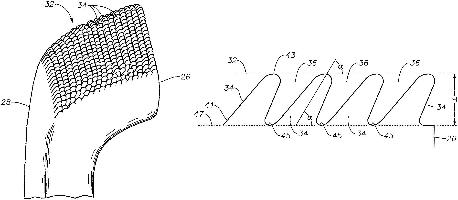
FIG. 2 illustrates an example forceps 20 within the scope of the present disclosure. The forceps 20 includes a textured surface 30 formed of a plurality of surface features, shown in FIGS. 3 and 4, for example. In the illustrated example, the textured surface 30 is formed into and along a distal surface 32 of the forceps jaws 28. The textured surface 30 increases friction between the forceps 10 and the ILM 12 by providing a higher coefficient of friction. With a higher coefficient of friction, the normal force needed to engage the ILM 12 is reduced. As a result of the reduced normal force, an indentation formed in the retina 14 and ILM 12 is reduced. The reduced normal force imparted by the jaws 28 of the forceps 20 reduces the risk of injury to the retina 14. With a lower normal force applied to the ILM 12 and the corresponding reduction in indentation formed in the retina 14 and ILM 12, the risk of trapping a portion of the retina 14 between tips 26 of the forceps jaws 28 is also reduced, which, in turn, also reduces the risk of injury to the retina 14 both when the forceps jaws 28 are closed and peeling of the ILM 12 is commenced.
FIG. 4 is a magnified image of the textured surface 30 shown in FIG. 3. The textured surface 30 includes a plurality of surface features or microposts 34. In the illustrated example, the microposts 34 are formed by application of laser energy to the distal surface 32 of the forceps jaws 28. The textured surface 30 works to increase a coefficient of friction between the forceps 20 and the ILM 12. As a result, a size of the normal force needed to grasp the ILM 12 with the forceps 20 is decreased. Therefore, a user, such as a surgeon, is able to apply a lower normal force to the ILM 12 and retina 14 with the forceps 20 in order to engage the ILM 12. Consequently, the risk of injury to the retina 14 is decreased.
FIG. 5 is a view of the textured surface 30 taken normal to the microposts 34 and shows an edge 50 defined by the tip 26 of the forceps jaw 28. FIG. 5 shows a plurality of laser cuts or traces 36 and 42 formed in the distal surface 32. The plurality of laser traces 36 and 42 define an array of the microposts 34. In some implementations, a laser beam used to form the laser traces 42 may be normal or substantially normal to the distal surface 32 of the forceps jaws 28. In this context, the term "substantially normal" may account for variations of an incident laser beam from being perpendicular to the distal surface 32 due to, for example, variations due to a fixed position of the laser source and a curvature of the distal surface 32, variations in the distal surface 32, misalignment of the laser source, and variations in a targeting and directional system used to control movement of the laser beam when forming the laser traces 42.
FIG. 6 shows a cross-sectional view of the textured surface 30 taken along line AA and showing the microposts 34 in profile. The distal surface 32 into which the textured surface 30 is formed is illustrated as a dotted line. A laser beam used to form the traces 36 may be incident to the distal surface 32 at an angle .alpha.. In some implementations, a femtosecond or picosecond laser may be used. Further, in some implementations, the laser may be a solid-state laser. The angle .alpha. is measured relative to the distal surface 32. In some implementations, the angle .alpha. may be within a range of 10.degree. to 90.degree., where 90.degree. would be perpendicular to the distal surface 32. In some implementations, the angle .alpha. may be within a range of 20.degree. to 70.degree.; 20.degree. to 55.degree.; 30.degree. to 60.degree.; 40.degree. to 50.degree.; 20.degree. to 50.degree.; or 30.degree. to 45.degree.. As shown in FIG. 6, in addition to the microposts 34 being illustrated at an angle as a result of the angle .alpha. of the traces 36, the illustrated microposts 34 also include a tapered profile. Thus, a cross sectional size of the microposts 34 is larger at towards a base 41, i.e., at a location where the microposts 34 are attached to the forceps jaws 28, and decreases towards an end 43. Although FIG. 6 shows all of the microposts 34 as being incident at the same angle, the scope of the disclosure is not so limited. Rather, in other implementations, an angle .alpha. of one or more of the microposts 34 may vary from one or more other microposts 34.
As the example shown in FIG. 6 illustrates, the angle .alpha. results in the microposts 34 inclining towards the tip 26. However, the scope of the disclosure is not so limited. Thus, in other implementations, the microposts 34 may be inclined in any direction relative to the tip 26. Further, in other implementations, the one or more of the microposts 34 may be included in a direction different from one or more other microposts 34.
A height H of the microposts 34, measured from a trough 45 of the traces 36 and measured perpendicularly from the effective surface 47 defined by a surface passing through the troughs 45. In some implementations, the height H may be 3 .mu.m to 10 .mu.m. In other implementations, the height H may be 3.5 .mu.m to 10 .mu.m. In other implementations, the height H may be 3.0 to 7 .mu.m; 3.5 .mu.m to 7 .mu.m; or 5 .mu.m to 7 .mu.m. In still other implementations, the height H of the microposts 34 may be smaller than 3 .mu.m or larger than 10 .mu.m. Further, the heights H of the microposts 34 may vary across the textured surface 30.
In some implementations, the microposts 34 have a four-sided pyramidal shape, as shown, for example, in FIG. 11. FIG. 11 shows the micropost 34 formed on a distal textured surface of forceps jaw 28 proximate to the tip 26. While FIG. 11 shows a single pyramidal micropost 34 for clarity purposes, it is to be understood that a plurality of the pyramidal microposts 34 would be formed on the distal textured surface of the forceps jaw 28.
As illustrated, the pyramidal microposts 34 include four walls that include a leading wall 200, a trailing wall 210, and two side walls 220. The example of FIG. 11 shows an obliquely formed pyramidal micropost 34. In this example, the leading wall 200 is oriented towards the tip 26 of the forceps jaw 28 with the trailing side 210 oriented away from the tip 26 of the forceps jaw 28. The walls 200, 210, and 220 taper from a base 230 to a point 240. The pyramidal microposts 34 may be formed at an oblique angle, as illustrated, for example in FIG. 6, or at a non-oblique angle, as illustrated, for example, in FIGS. 9 and 10. In some instances, the sides of the pyramidal microposts 34 (and, hence, the microposts 34 themselves) are formed as a result of removal of material of the forceps jaw 28 due to ablation during laser forming. In other instances, the wall of the pyramidal microposts 34 may be formed by grinding, etching, or other type of applicable forming method.
The walls 200, 210, and 220 of the pyramidal microposts 34 are disposed at an angle relative to a plane defined by the base 230. In some instances, a length K of the microposts 34 at the base 230 may be within a range of 7 .mu.m and 13 .mu.m. A width M of the microposts 34 may be within the range of 7 .mu.m and 13 .mu.m. In some instances, the length K of one or more of the microposts 34 may be larger than the width M. In other instances, the length K of one or more of the microposts 34 may be smaller than the width M. In still other instances, the length K of one or more of the microposts 34 may be the same as the width M. In some implementations, a height of H (as shown oriented in FIG. 6) may be within the range of 3 .mu.m to 7 .mu.m. The point 240 may have a thickness (as measured in a cross-section of the point 240 defined by a plane parallel to a plane defined by the base 230) in a range of 1.0 .mu.m to 0.5 .mu.m. The point 240 may have a cross-sectional shape (taken along a plane parallel with the base 230 of the micropost 34) that generally corresponds to the shape of the pyramidal micropost 34 at its base 230. Thus, the thickness of the point 240 may be the dimension K or M measured at the point 240. As a practical matter, on the scale contemplated by the present disclosure, the dimensions K and M of the point 240 may not be clearly distinguishable in some implementations. Thus, the thickness of the point 230 may be a largest dimension of the point 230.
Although, pyramidal microposts are illustrated, the scope of the disclosure is not so limited. Rather, in other implementations, the microposts may have a cylindrical shape having a constant cross-section along an entire length of the microposts. Further, in other implementations, a cross-sectional shape of the microposts (taken along a plane parallel with the base of the micropost) may be circular, polygonal, or rectangular, square, or any other desired shape.
It is believe that, when microposts 34 of the present disclosure, particularly in the pyramidal form, the points 240 of the microposts 34 penetrate a membrane, such as the ILM, to aid in removal thereof.
Referring again to FIG. 5, a cross-sectional view of the textured surface taken near the bases 41 of the microposts 34 is illustrated. A width of the laser traces 36 and 42 may be within a range of approximately 2 .mu.m to 30 .mu.m. In some implementations, the width of the laser cuts 36 and 42 may be within a range of 2 .mu.m to 10 .mu.m. In still other implementations, a width of one or more of the laser cuts 36 and 42 may vary from one or more other laser cuts 36 and 42. Thus, in some implementations, a width of one or more laser cuts 36 may be larger or smaller than a width of one or more other laser cuts 36. Similarly, a width of one or more laser cuts 42 may be larger or smaller than a width of one or more other laser cuts 42.
As shown in FIG. 5, a width W1 defines a distance between adjacent traces 36, and a width W2 defines a distance between adjacent traces 42. In some implementations, the widths W1 and W2 may be within a range of 2 .mu.m to 15 .mu.m or within the range of 2 .mu.m to 10 .mu.m. In other implementations, the widths W1 and W2 may be within a range of 2 .mu.m to 7 .mu.m. In other implementations, the widths W1 and W2 may be within a range of 2 .mu.m to 5 .mu.m. In some implementations, the widths W1 and W2 may be different from one another. That is, in some instances, the width W1 of the microposts 34 may be larger or smaller than the width W2. Additionally, cross-sectional sizes of the microposts 34 may vary along the textured surface 30. Thus, in some instances, one or more of the microposts 34 may have a width W1 that is the same as the width W2, while one or more other microposts 34 may have a width W1 that is different from the width W2. Thus, the sizes of the microposts 34 may vary along the textured surface 30.
Near the bases 41 of the microposts 34, the microposts 34 may have cross-sectional dimensions of a Z1 and Z2. The dimensions Z1 and Z2 may substantially correspond to width W1 and a width W2 but be reduced as a result of a width of the laser trace itself. Thus, in some implementations, a size of the dimensions Z1 and/or Z2 may be within a range of 3 .mu.m to 10 .mu.m; 4 .mu.m to 9 .mu.m; or 5 .mu.m to 8 .mu.m. These ranges are provided only as example. Thus, in other implementations, dimensions Z1 and Z2 may be smaller than 3 .mu.m or larger than 10 .mu.m. The size of dimensions Z1 and Z2 may be selected to be any desired size.
FIG. 5 shows an orthogonal grid pattern formed by the laser traces 36 and 42. As shown in FIG. 5, the traces 36 are parallel or may be substantially parallel to the edge 50. The traces 36 may be described as substantially parallel to the edge 50 due, for example, to small variations in orientation of the traces 36 or the edge 50 due to variations in manufacturing or minor misalignments that may result during manufacturing. For example, in some instances, the laser used to form the laser traces 36 may be misaligned with the forceps 20 such that the traces 36 may form slight angle with the edge 50 although a parallel orientation was intended. Also, formation of the tips 26 may result in the tips 26 being slightly out of parallel with the resulting traces 26. Thus, while a parallel relationship between the edge 20 and the traces 36 may be intended, variations in manufacturing may result in a slight deviation between the orientation of the edge 30 and the traces 36.
However, the scope of the disclosure is not so limited. Rather, any pattern may be formed in the distal surface 32 of the forceps jaws 28. FIGS. 7-8 show other example patterns of microposts 34 that may be formed on the distal surface 32 of the forceps jaws 28. FIG. 7 shows a pattern in which the laser traces 36 and 42 are oblique to the edge 50 formed by the tips 26. Similar to the example shown in FIG. 5 and described above, the laser traces 36 and 42 form microposts 34 having a width W1 and a width W2. In some instances, the traces 36 and 42 may be selected such that the widths W1 and W2 are the same. In other instances, the widths W1 and W2 may be different. Still further, one or more of the widths W1 and W2 may vary along the textured surface 30 to produce microposts 34 of varying sizes.
FIG. 8 shows another example pattern formed by laser traces 36 and 42. In this example, the traces 36 are circular or scalloped shaped whereas the traces 42 are straight. In some implementations, spacing S between the traces 36 may be equal. In other instances, the spacing S may vary over the textured surface 30. Similarly, in some implementations, width W2 between the traces 42 may be equal. In other implementations, the textured surface 30 may include different widths W2. While FIGS. 7 and 8 show two additional examples of patterns of microposts 34 that may be formed on the textured surface 30, any other desired pattern is also included within the scope of the present disclosure.
FIGS. 9 and 10 illustrate another example forceps 90. The forceps 90 may be similar to the forceps 20, described above. However microposts 92 of a textured surface 94 formed on the distal surface 96 of forceps jaws 98 do not include an inclination. That is, the angle .alpha. is 90.degree.. Also similar to the example forceps 20 described above, the distances W1 and W2 between respective adjacent laser traces 100 and 102 and the sizes Z1 and Z2 and height H of the microposts 92 may have the same ranges described above.
Although the present disclosure is made in context of forceps, the scope of the disclosure is not so limited. Rather, a textured surface of a type described herein may be applied other types of instruments, such as, for example, scissors, scrapers, spatulas, etc., and may be used. Further, instruments having a textured surface as described herein may be used in other medical or technological areas.
While the various examples described above are described in the context of forming surface features using laser energy. However, the scope of the disclosure is not so limited. Rather, other processes may be used to form the microposts and are within the scope of the present disclosure. For example, chemical etching may also be used to for the microposts by chemically removing material. The material removed for a surface to define the microposts may be in the form of a plurality of valley or grooves (referred to collectively as "traces"). Thus, while laser traces are described in the context of traces formed by laser energy, the general term "trace" is used to describe a grooves, cuts, or valleys formed in a surface of an instrument, for example, to define a surface texture and surface features thereof.
In other implementations, the traces may be formed via photolithography. For example, in some instances, a desired pattern may be masked on a portion of the surgical instrument, such as with the use of a photoresist material. The photoresist material may be positive photoresist or a negative photoresist. The photoresist material may be exposed to radiation (e.g., ultraviolet or other frequency of radiation) to define the pattern to be etched. A chemical solution may be applied to the masked area to remove a portion of the photoresist material so that the desired pattern is defined. The masked surface may be washed, and an etchant may be applied to the portion of the surgical instrument having an exposed surface defined by the pattern (i.e., the area on which the photoresist is not present) in order to etch the surface of the surgical material and form the desired topography, e.g., traces.
In some implementations, surgical instruments within the scope of this disclosure may be formed of metal in whole or in part, such as, for example, steel (e.g., stainless steel), titanium, or other metal. In other implementations, the instruments may be formed from a polymer in whole or in part. For example, the instruments may be a polymer tip instrument in which a tip portion of the instrument that is made to come into contact with tissue is formed of a polymer. In other instances, the instruments may be formed, at least in part, of glass. A texture of a type described herein may be formed on a surface of the instruments formed from a polymer by, for example, a chemical etching (e.g., with the use of a photoresist material), laser energy, grinding, molding, or other method.
Persons of ordinary skill in the art will appreciate that the implementations encompassed by the present disclosure are not limited to the particular exemplary implementations described above. In that regard, although illustrative implementations have been shown and described, a wide range of modification, change, combination, and substitution is contemplated in the foregoing disclosure. It is understood that such variations may be made to the foregoing without departing from the scope of the present disclosure. Accordingly, it is appropriate that the appended claims be construed broadly and in a manner consistent with the present disclosure.
* * * * *
References
D00000
D00001
D00002
D00003
D00004
D00005
D00006
XML
uspto.report is an independent third-party trademark research tool that is not affiliated, endorsed, or sponsored by the United States Patent and Trademark Office (USPTO) or any other governmental organization. The information provided by uspto.report is based on publicly available data at the time of writing and is intended for informational purposes only.
While we strive to provide accurate and up-to-date information, we do not guarantee the accuracy, completeness, reliability, or suitability of the information displayed on this site. The use of this site is at your own risk. Any reliance you place on such information is therefore strictly at your own risk.
All official trademark data, including owner information, should be verified by visiting the official USPTO website at www.uspto.gov. This site is not intended to replace professional legal advice and should not be used as a substitute for consulting with a legal professional who is knowledgeable about trademark law.