Electrical connector for a battery module
Schwindt , et al. April 13, 2
U.S. patent number 10,978,750 [Application Number 15/321,740] was granted by the patent office on 2021-04-13 for electrical connector for a battery module. This patent grant is currently assigned to Robert Bosch GmbH. The grantee listed for this patent is Robert Bosch GmbH. Invention is credited to Stefan Baumann, Carsten Mueller, Andreas Ruehle, Emilia Schwindt.

| United States Patent | 10,978,750 |
| Schwindt , et al. | April 13, 2021 |
Electrical connector for a battery module
Abstract
Disclosed is a battery module comprising at least one battery cell and a cell monitoring unit which is connected in an electrically conducting manner to a flexible circuit board by at least one bonding wire and/or at least one bonding strip.
| Inventors: | Schwindt; Emilia (Stuttgart, DE), Mueller; Carsten (Stuttgart, DE), Baumann; Stefan (Altenriet, DE), Ruehle; Andreas (Beitigheim-Bissingen, DE) | ||||||||||
|---|---|---|---|---|---|---|---|---|---|---|---|
| Applicant: |
|
||||||||||
| Assignee: | Robert Bosch GmbH (Stuttgart,
DE) |
||||||||||
| Family ID: | 1000005488577 | ||||||||||
| Appl. No.: | 15/321,740 | ||||||||||
| Filed: | June 1, 2015 | ||||||||||
| PCT Filed: | June 01, 2015 | ||||||||||
| PCT No.: | PCT/EP2015/062119 | ||||||||||
| 371(c)(1),(2),(4) Date: | December 22, 2016 | ||||||||||
| PCT Pub. No.: | WO2015/197311 | ||||||||||
| PCT Pub. Date: | December 30, 2015 |
Prior Publication Data
| Document Identifier | Publication Date | |
|---|---|---|
| US 20170133725 A1 | May 11, 2017 | |
Foreign Application Priority Data
| Jun 26, 2014 [DE] | 10 2014 212 247.3 | |||
| Current U.S. Class: | 1/1 |
| Current CPC Class: | H05K 1/189 (20130101); H01M 12/06 (20130101); H01M 10/052 (20130101); H01M 10/425 (20130101); H01M 50/502 (20210101); H01M 10/482 (20130101); H01L 2924/19107 (20130101); H05K 2201/10037 (20130101); H01L 2224/48091 (20130101); H01M 2010/4271 (20130101); H01M 2010/4278 (20130101); H01L 2224/48091 (20130101); H01L 2924/00014 (20130101) |
| Current International Class: | H01M 10/42 (20060101); H01M 12/06 (20060101); H01M 10/052 (20100101); H05K 1/18 (20060101); H01M 10/48 (20060101) |
References Cited [Referenced By]
U.S. Patent Documents
| 4884335 | December 1989 | McCoy |
| 2007/0187807 | August 2007 | Lee |
| 2008/0241667 | October 2008 | Kohn |
| 2009/0117458 | May 2009 | Yun |
| 2011/0274952 | November 2011 | Itagaki et al. |
| 2013/0244499 | September 2013 | Heck et al. |
| 2013/0252032 | September 2013 | Zhao |
| 2014/0017533 | January 2014 | Nishihara et al. |
| 2014/0363704 | December 2014 | Bachmann |
| 2015/0364740 | December 2015 | De Arroyabe |
| 100596257 | Mar 2010 | CN | |||
| 102009036086 | Feb 2011 | DE | |||
| 102011078548 | Jan 2012 | DE | |||
| 102011016373 | Oct 2012 | DE | |||
| 102012212368 | Jan 2013 | DE | |||
| 102011081964 | Mar 2013 | DE | |||
| 102012205020 | Oct 2013 | DE | |||
| 1577689 | Sep 2005 | EP | |||
Other References
|
Machine Translation provided by Google Patents of DE102009036086A1 originally published Feb. 17, 2011 to Abraham et al. cited by examiner . Certified Human Translation of DE102009036086 originally published to Abraham et al. in 2009. cited by examiner . Google Patents machine translation of CN100596257 originally published to Xianwei et al in 2010. cited by examiner . International Search Report for Application No. PCT/EP2015/062119 dated Jul. 30, 2015 (English Translation, 3 pages). cited by applicant. |
Primary Examiner: Crepeau; Jonathan
Attorney, Agent or Firm: Michael Best & Friedrich LLP
Claims
The invention claimed is:
1. A battery module (1) having multiple battery cells (2(1), 2(2), 2(3), 2(n)), each battery cell having at least two cell terminals, wherein one of the cell terminals of each of the battery cells is electrically conductively connected to a cell terminal of different polarity of an adjacent one of the battery cells by at least one cell connector, wherein the battery module (1) comprises a cell monitoring unit (4), characterized in that the cell monitoring unit (4) is electrically conductively connected to a flexible circuit board (3) by means of at least one bonding wire (5(1)) and/or at least one bonding strip (5(2)), wherein a top surface of the flexible circuit board is connected to a top surface of the cell monitoring unit by the at least one bonding wire (5(1)) and/or the at least one bonding strip (5(2)) to facilitate replacement of the cell monitoring unit, wherein the cell monitoring unit is reversibly mechanically connected to the flexible circuit board, and wherein the at least one cell connector is implemented as bonding wires and/or bonding strips.
2. The battery module (1) as claimed in claim 1, characterized in that aluminum, aluminum-silicon, copper and/or gold is used as material for the bonding wire (5(1)) and/or the bonding strip (5(2)).
3. The battery module (1) as claimed in claim 1, characterized in that the bonding wire (5(1)) has a diameter between 100 .mu.m and 500 .mu.m.
4. The battery module (1) as claimed in claim 1, characterized in that the bonding strip (5(2)) has a rectangular shape with a width between 30 .mu.m and 3000 .mu.m and a height between 10 .mu.m and 500 .mu.m.
5. The battery module (1) as claimed in claim 1, characterized in that the bonding wire (5(1)) and/or the bonding strip (5(2)) have/has a length between 1 mm and 30 mm.
6. The battery module (1) as claimed in claim 1, characterized in that the cell monitoring unit (4) comprises at least one voltage sensor, a current sensor, a temperature sensor, a resistor and/or a battery management system.
7. The battery module (1) as claimed in claim 1, characterized in that the cell monitoring unit (4) is arranged within a region of the flexible circuit board (3), and the cell monitoring unit (4) and the flexible circuit board (3) are screwed to one another.
8. The battery module (1) as claimed in claim 1, characterized in that the flexible circuit board (3) comprises, as base material, PET (polyester), PEM (polyethylene naphthalate) and/or PI (polyimide).
9. A method for producing an electrically conductive connection as claimed in claim 1, characterized in that an electrically conductive connection is produced between the cell monitoring unit (4) and the flexible circuit board (3) by means of thermosonic ball-wedge bonding, ultrasonic wedge-wedge bonding and/or thermocompression bonding of at least one bonding wire (5(1)) and/or bonding strip (5(2)).
10. A battery that is lithium-ion, lithium-sulfur and/or lithium-air, comprising a battery module (1) as claimed in claim 1.
11. The battery as claimed in claim 10, characterized in that aluminum, aluminum-silicon, copper and/or gold is used as material for the bonding wire (5(1)) and/or the bonding strip (5(2)).
12. The battery as claimed in claim 10, characterized in that the bonding wire (5(1)) has a diameter between 100 .mu.m and 500 .mu.m.
13. The battery as claimed in claim 10, characterized in that the bonding strip (5(2)) has a rectangular shape with a width between 30 .mu.m and 3000 .mu.m and a height between 10 .mu.m and 500 .mu.m.
14. The battery as claimed in claim 10, characterized in that the bonding wire (5(1)) and/or the bonding strip (5(2)) have/has a length between 1 mm and 30 mm.
15. The battery as claimed in claim 10, characterized in that the cell monitoring unit (4) comprises at least one voltage sensor, a current sensor, a temperature sensor, a resistor and/or a battery management system.
16. The battery as claimed in claim 10, characterized in that the cell monitoring unit (4) is arranged within a region of the flexible circuit board (3), and the cell monitoring unit (4) and the flexible circuit board (3) are screwed to one another.
17. The battery as claimed in claim 10, characterized in that the flexible circuit board (3) comprises, as base material, PET (polyester), PEM (polyethylene naphthalate) and/or PI (polyimide).
Description
BACKGROUND OF THE INVENTION
The invention relates to an electrical connector for a battery module.
Electrical connectors which electrically conductively connect at least one battery cell of a battery module to a detection unit, for example by welding electrically conductive wires to the battery cell and the detection unit, are known from the prior art.
A disadvantage of the known prior art is the fact that various production steps are necessary in order to produce and assemble an electrically conductive connection between a battery cell and a detection unit. An electrical connector is produced, by way of example, from electrically conductive wires, wherein the wires must have an exact length and must be able to bend. Each electrical connector is welded or adhesively bonded to at least one battery cell and a detection unit. The electrically conductive wires are then combined to form a cable harness.
SUMMARY OF THE INVENTION
The approach according to the invention, by contrast, has the advantage that a cell monitoring unit is electrically conductively connected to a flexible circuit board by means of at least one bonding wire and/or at least one bonding strip.
Aluminum, aluminum-silicon, copper, or gold is advantageously used as material for the bonding wire and/or the bonding strip in order to reduce line losses. The bonding wire and/or the bonding strip can further advantageously be produced by means of roll bonding, for example by applying a copper layer to an aluminum layer, wherein this connection is mechanically non-detachable.
Depending on a specific energy density, for example 200 Wh/kg, and a number of battery cells of the battery module in question, the bonding wire advantageously has a diameter between 100 .mu.m and 500 .mu.m, such that a maximum current flow of, for example, 20 A through the bonding wire is ensured without the bonding wire becoming damaged, for example.
Depending on a specific energy density, for example 240 Wh/kg, and a number of battery cells of the battery module in question, the bonding strip advantageously has a rectangular cross-section with a width between 30 .mu.m and 3000 .mu.m and a height between 10 .mu.m and 500 .mu.m, such that a maximum current flow of, for example, 80 A through the bonding strip is ensured without the bonding strip becoming damaged, for example.
The bonding wire and/or the bonding strip advantageously have/has a length between 1 mm and 30 mm, such that a mechanical stability is ensured and low line resistances are achieved.
The cell monitoring unit advantageously comprises at least one voltage sensor, a current sensor, a temperature sensor, a resistor and/or a battery management system, such that a voltage of individual battery cells is detected by the cell monitoring unit, for example.
The cell monitoring unit is advantageously arranged within a region of the flexible circuit board, and the cell monitoring unit and the flexible circuit board are adhesively bonded, screwed, soldered or welded to one another and/or mechanically connected to one another by means of locking mechanisms, whereby a particularly high strength is achieved and a failure rate, for example on account of vibrations, is reduced.
The flexible circuit board advantageously comprises, as base material, PET (polyester), PEM (polyethylene naphthalate) and/or PI (polyimide), wherein conductive tracks are applied to the base material by means of printing methods or lithography.
In order to produce an electrically conductive connection between the bonding wire and/or the bonding strip and a bus bar, a conductive track and/or a contact face, various method variants are used, such as thermocompression bonding (TC bonding), thermosonic ball-wedge bonding (TS bonding) and/or ultrasonic wedge-wedge bonding (US bonding).
These methods are selected for example on the basis of the used material of the bonding wires or of the bonding strip. TC bonding is thus used rarely for wire bonding since the high forces and temperatures necessary to produce a connection may damage the connection elements, whereas the method is suitable however for strip bonding. If gold or copper is used as material for the bonding wires or bonding strips, TS bonding is suitable. If, by contrast, aluminum or aluminum-silicon is used as material for the bonding wires or bonding strips, US bonding is advantageously suitable.
A space-optimized arrangement of battery cells is advantageously possible on account of the smaller spatial requirement of the flexible circuit board, the cell monitoring unit, and the bonding wires and/or bonding strips compared to previously used cable harnesses.
A new geometry and/or a new arrangement of battery cells is advantageously possible on account of the mechanical flexibility of the bonding wires and/or the bonding strips as cell connectors. New geometries can be advantageously implemented at bonding machines with few changes required.
With use of flexible circuit boards, cell monitoring units, bonding wires and/or bonding strips, a repair of defective electrical connections is advantageously possible with comparatively low outlay compared to previous connection techniques.
Fewer production steps are advantageously possible for the contacting of battery cells and the connection means by bonding wires and/or bonding strips, whereby a lower technical outlay is necessary for a production process of battery modules and a higher degree of automation is made possible.
The battery module is advantageously used in a lithium-ion, a lithium-sulfur and/or a lithium-air battery.
BRIEF DESCRIPTION OF THE DRAWINGS
Exemplary embodiments of the invention are illustrated in the drawings and will be explained in greater detail in the following description.
In the drawings:
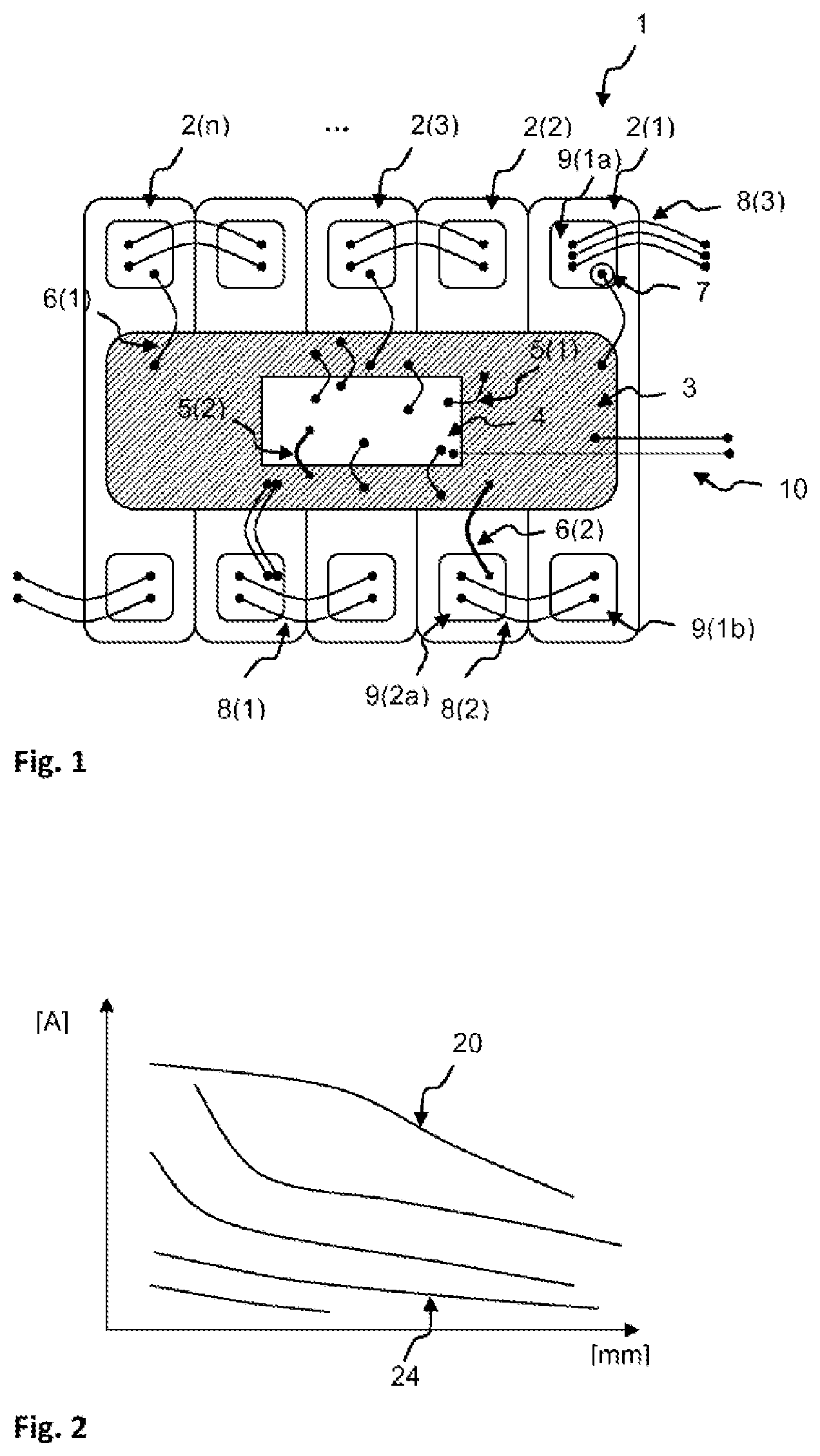
FIG. 1 shows an embodiment of the battery module according to the invention; and
FIG. 2 shows a graph of the exemplary current carrying capacity as a function of the diameter of a bonding wire.
DETAILED DESCRIPTION
Like reference signs designate like device components in all drawings.
FIG. 1 shows a battery module 1 having a plurality of battery cells 2(1), 2(2), 2(3), 2(n), wherein each battery cell 2(1), 2(2), 2(3), 2(n) has at least two cell terminals 9(1a), 9(1b), 9(2a).
By way of example, the cell terminal 9(1a) in FIG. 1 is mechanically and electrically conductively connected to a positive pole of the battery cell 2(1), and the cell terminal 9(1b) is mechanically and electrically conductively connected to a negative pole of the battery cell 2(1). Cell terminals of different polarity are electrically conductively connected to one another by means of at least one cell connector 8(1), 8(2), 8(3), for example the cell terminal 9(1b) of the battery cell 2(1) is connected to the cell terminal 9(2a) of the battery cell 2(2). The cell connectors 8(1), 8(2), 8(3) are embodied as bonding wires and/or bonding strips.
In accordance with the invention the battery module 1 comprises a flexible circuit board 3 and a cell monitoring unit 4. In the embodiment shown in FIG. 1 the cell monitoring unit 4 is arranged within a region of the flexible circuit board 3, and the flexible circuit board 3 and the cell monitoring unit 4 are adhesively bonded to one another.
In alternative embodiments a mechanical connection is established between the flexible circuit board 3 and the cell monitoring unit 4 by screwing, soldering and/or welding.
In a further embodiment the cell monitoring unit 4 is realized directly on the flexible circuit board 3 by means of electronic components, whereby a rigid circuit board of the cell monitoring unit 4 is advantageously spared.
In a further embodiment the flexible circuit board 3 and/or the cell monitoring unit 4 has a locking device so that, by way of example, the cell monitoring unit 4 is reversibly mechanically connected to the flexible circuit board 3 and is advantageously swapped in the event of a defect.
The flexible circuit board 3 in the shown embodiment comprises bus bars and/or devices for balancing the charge of the battery cells 2(1), 2(2), 2(3), 2(n). The cell terminals 9(1a), 9(1b), 9(2a) are electrically conductively connected to the flexible circuit board 4, for example to the bus bars, conductive tracks, contact faces and/or the devices for charge balancing, by means of a least one bonding wire 6(1) and/or bonding strip 6(2). In the shown embodiment a temperature sensor 7 is advantageously connected to the flexible circuit board 3.
The cell monitoring unit 4 comprises at least one voltage sensor, a current sensor, a temperature sensor, a resistor and/or a battery management system in order to determine battery module properties for the battery module 1 such as a state of charge (SOC), state of health (SOH) and internal resistance. The cell monitoring unit 4 is electrically conductively connected to the flexible circuit board 3 by means of at least one bonding wire 5(1) and/or a bonding strip 5(2) and by way of example can detect a voltage of an individual battery cell 2(1), 2(2), 2(3), 2(n) or all battery cells 2(1), 2(2), 2(3), 2(n) by means of the voltage sensor.
The reliability of battery modules 1 can advantageously be increased by the cell monitoring unit, since defects can be identified early on, such that safety measures can be taken even before a defect occurs and, for example, individual batteries 2(1), 2(2), 2(3), 2(n) can be switched on or off.
In a further embodiment the cell monitoring unit 4 and/or the flexible circuit board 3 are connected by means of electrically conductive connections and/or optical connections to further cell monitoring units 4, flexible circuit boards 3 and/or battery management systems, for example by means of a cable connection and/or by means of a bus system.
A central battery management system advantageously detects battery module properties of a number of battery modules 1 in order to determine battery properties on the basis of the battery module properties.
In FIG. 2 a current carrying capacity (in amperes) of a bonding wire diameter to bonding wire length ratio is plotted over a length of a bonding wire (in millimeters). On the basis of the illustrated curves, the diameter can be selected depending on a necessary current capacity of the bonding wire, such that a weight reduction is achieved as a result of a lower material requirement and a reduction of having at least one battery cell transition resistances. By way of example, the current carrying capacity for bonding wires 20 and 24 made of aluminum and having a diameter of 500 .mu.m and 200 .mu.m respectively is illustrated in FIG. 2
If a particularly high demand is placed on a mechanical stability of a bonding connection of the bonding wire, for example on account of a high ambient temperature of the battery module 1 or due to strong vibrations, a larger diameter of the bonding wire is selected, such that a tear-off value with a diameter of the bonding wire of 200 .mu.m is 500 cN, for example.
* * * * *
D00000
D00001
XML
uspto.report is an independent third-party trademark research tool that is not affiliated, endorsed, or sponsored by the United States Patent and Trademark Office (USPTO) or any other governmental organization. The information provided by uspto.report is based on publicly available data at the time of writing and is intended for informational purposes only.
While we strive to provide accurate and up-to-date information, we do not guarantee the accuracy, completeness, reliability, or suitability of the information displayed on this site. The use of this site is at your own risk. Any reliance you place on such information is therefore strictly at your own risk.
All official trademark data, including owner information, should be verified by visiting the official USPTO website at www.uspto.gov. This site is not intended to replace professional legal advice and should not be used as a substitute for consulting with a legal professional who is knowledgeable about trademark law.