Scroll fluid machine and method for producing same
Sato , et al. April 13, 2
U.S. patent number 10,975,866 [Application Number 16/090,725] was granted by the patent office on 2021-04-13 for scroll fluid machine and method for producing same. This patent grant is currently assigned to MITSUBISHI HEAVY INDUSTRIES THERMAL SYSTEMS, LTD.. The grantee listed for this patent is MITSUBISHI HEAVY INDUSTRIES THERMAL SYSTEMS, LTD.. Invention is credited to Yohei Hotta, Yoshiyuki Kimata, Hajime Sato.
| United States Patent | 10,975,866 |
| Sato , et al. | April 13, 2021 |
Scroll fluid machine and method for producing same
Abstract
Provided is a scroll fluid machine capable of effectively achieving performance of a tip seal installed in a tooth crest of a wall including an inclined portion. The inclined portion in which a distance between opposing surfaces of end plates facing each other gradually decreases from an outer peripheral side toward an inner peripheral side is provided. A tip seal (7) configured to make contact with a tooth base facing the tip seal (7) to perform sealing against fluid is provided in tip seal groove (3d) formed in a tooth crest of a wall (3b) corresponding to the inclined portion. In a stop state where a scroll (3) does not perform compression of fluid, an inclination height (Ls') of the tip seal (7) is smaller than an inclination height (Ls) of the wall (3b).
| Inventors: | Sato; Hajime (Tokyo, JP), Kimata; Yoshiyuki (Tokyo, JP), Hotta; Yohei (Tokyo, JP) | ||||||||||
|---|---|---|---|---|---|---|---|---|---|---|---|
| Applicant: |
|
||||||||||
| Assignee: | MITSUBISHI HEAVY INDUSTRIES THERMAL
SYSTEMS, LTD. (Tokyo, JP) |
||||||||||
| Family ID: | 1000005484711 | ||||||||||
| Appl. No.: | 16/090,725 | ||||||||||
| Filed: | August 14, 2017 | ||||||||||
| PCT Filed: | August 14, 2017 | ||||||||||
| PCT No.: | PCT/JP2017/029243 | ||||||||||
| 371(c)(1),(2),(4) Date: | October 02, 2018 | ||||||||||
| PCT Pub. No.: | WO2018/034256 | ||||||||||
| PCT Pub. Date: | February 22, 2018 |
Prior Publication Data
| Document Identifier | Publication Date | |
|---|---|---|
| US 20190120229 A1 | Apr 25, 2019 | |
Foreign Application Priority Data
| Aug 19, 2016 [JP] | JP2016-161210 | |||
| Current U.S. Class: | 1/1 |
| Current CPC Class: | F04C 18/0284 (20130101); F04C 27/00 (20130101); F04C 27/005 (20130101); F04C 18/0215 (20130101); F04C 18/0276 (20130101); F04C 2210/26 (20130101) |
| Current International Class: | F04C 18/02 (20060101); F04C 27/00 (20060101); F04C 23/00 (20060101); F01C 19/00 (20060101) |
References Cited [Referenced By]
U.S. Patent Documents
| 4477238 | October 1984 | Terauchi |
| 5496161 | March 1996 | Machida |
| 6050792 | April 2000 | Shaffer |
| 6746224 | June 2004 | Itoh |
| 8157550 | April 2012 | Kudo |
| 2002/0054821 | May 2002 | Takeuchi |
| 2009/0208356 | August 2009 | Ginies et al. |
| 2010/0092318 | April 2010 | Sato et al. |
| 2012/0288394 | November 2012 | Murakami et al. |
| 2012/0315173 | December 2012 | Nakamura et al. |
| 2014/0308146 | October 2014 | Hirata et al. |
| 2017/0370219 | December 2017 | Takeuchi et al. |
| 102052302 | May 2011 | CN | |||
| 2527655 | Nov 2012 | EP | |||
| 2538083 | Dec 2012 | EP | |||
| 2894338 | Jul 2015 | EP | |||
| 7-35061 | Feb 1995 | JP | |||
| 11-190287 | Jul 1999 | JP | |||
| 2001-12365 | Jan 2001 | JP | |||
| 2002-70766 | Mar 2002 | JP | |||
| 2006342776 | Dec 2006 | JP | |||
| 2008-133778 | Jun 2008 | JP | |||
| 2008-163895 | Jul 2008 | JP | |||
| 2009-228476 | Oct 2009 | JP | |||
| 2010-196663 | Sep 2010 | JP | |||
| 2012-36825 | Feb 2012 | JP | |||
| 2014-80940 | May 2014 | JP | |||
| 2015-55173 | Mar 2015 | JP | |||
| 2016-102486 | Jun 2016 | JP | |||
Other References
|
English translatoin of JP 2006342776 by J Plat Pat Jun. 3, 2020. cited by examiner . Extended European Search Report, dated May 13, 2019, for European Application No. 17841496.7. cited by applicant . Extended European Search Report, dated May 31, 2019, for European Application No. 17841476.9. cited by applicant . Written Opinion of the International Searching Authority and International Search Report, dated Oct. 17, 2017, for International Application No. PCT/JP2017/029327, with English translations. cited by applicant . Written Opinion of the International Searching Authority and International Search Report, dated Oct. 24, 2017, for International Application No. PCT/JP2017/029241, with English translations. cited by applicant . Written Opinion of the International Searching Authority and International Search Report, dated Oct. 31, 2017, for International Application No. PCT/JP2017/029243, with English translations. cited by applicant . U.S. Office Action for U.S. Appl. No. 16/093,753, dated Jul. 24, 2020. cited by applicant . U.S. Office Action for U.S. Appl. No. 16/097,749, dated Sep. 15, 2020. cited by applicant. |
Primary Examiner: Wan; Deming
Attorney, Agent or Firm: Birch, Stewart, Kolasch & Birch, LLP.
Claims
The invention claimed is:
1. A scroll fluid machine comprising: a first scroll member including a first end plate and a first wall provided on the first end plate, the first wall having a spiral shape; and a second scroll member including a second end plate that is disposed to face the first end plate, and a second wall provided on the second end plate, the second scroll member being configured to relatively rotate in orbital motion with the second wall engaged with the first wall, the second wall having a spiral shape, wherein an inclined portion in which a distance between opposing surfaces of the first end plate and the second end plate facing each other gradually decreases from an outer peripheral side toward an inner peripheral side of the first wall and the second wall is provided, a tip seal is provided in groove portions formed in tooth crests of the first wall and the second wall corresponding to the inclined portion, the tip seal being configured to make contact with a tooth base facing the tip seal to perform sealing against fluid, and in a stop state where the scroll members do not perform compression of fluid, an inclination height of the tip seal is smaller than an inclination height of the wall, the inclination height of the tip seal is a difference between a height of the tip seal at a position corresponding to an outer peripheral side of the inclined portion of the first wall and a height of the tip seal at a position corresponding to an inner peripheral side of the inclined portion of the first wall and, a difference between a height of the tip seal at a position corresponding to an outer peripheral side of the inclined portion of the second wall and a height of the tip seal at a position corresponding to an inner peripheral side of the inclined portion of the second wall, and the inclination height of the wall is a difference between a height on the outer peripheral side of the inclined portion of the first wall and a height on the inner peripheral side of the inclined portion of the first wall and, a difference between a height on the outer peripheral side of the inclined portion of the second wall and a height on the inner peripheral side of the inclined portion of the second wall.
2. The scroll fluid machine according to claim 1, wherein a height of the tip seal in a height direction of the first wall and the second wall is greater than a difference between the inclination height of the wall and the inclination height of the tip seal.
3. The scroll fluid machine according to claim 2, wherein the tip seal is made of an elastically deformable material.
4. The scroll fluid machine according to claim 1, wherein the tip seal is made of an elastically deformable material.
5. A method of manufacturing a scroll fluid machine, the scroll fluid machine including: a first scroll member including a first end plate and a first wall provided on the first end plate, the first wall having a spiral shape; and a second scroll member including a second end plate that is disposed to face the first end plate, and a second wall provided on the second end plate, the second scroll member being configured to relatively rotate in orbital motion with the second wall engaged with the first wall, the second wall having a spiral shape, wherein an inclined portion in which a distance between opposing surfaces of the first end plate and the second end plate facing each other gradually decreases from an outer peripheral side toward an inner peripheral side of the first wall and the second wall is provided, and a tip seal is provided in groove portions formed in tooth crests of the first wall and the second wall corresponding to the inclined portion, the tip seal being configured to make contact with a tooth base facing the tip seal to perform sealing against fluid, the method comprising: installing the tip seal in the groove portions such that an inclination height of the tip seal is smaller than an inclination height of the wall; and installing the first scroll member and the second scroll member by engaging the first scroll member with the second scroll member after installing the tip seal, wherein the inclination height of the tip seal is a difference between a height of the tip seal at a position corresponding to an outer peripheral side of the inclined portion of the first wall and a height of the tip seal at a position corresponding to an inner peripheral side of the inclined portion of the first wall and, a difference between a height of the tip seal at a position corresponding to an outer peripheral side of the inclined portion of the second wall and a height of the tip seal at a position corresponding to an inner peripheral side of the inclined portion of the second wall, and the inclination height of the wall is a difference between a height on the outer peripheral side of the inclined portion of the first wall and a height on the inner peripheral side of the inclined portion of the first wall and a difference between a height on the outer peripheral side of the inclined portion of the second wall and a height on the inner peripheral side of the inclined portion of the second wall.
Description
TECHNICAL FIELD
The present invention relates to a scroll fluid machine and a method for manufacturing the same.
BACKGROUND ART
A scroll fluid machine in which a fixed scroll member including a spiral-shaped wall provided on an end plate and an orbiting scroll member including a spiral-shaped wall provided on an end plate are engaged with each other and rotated in orbital motion to compress or expand fluid is generally known.
A so-called stepped scroll compressor such as that disclosed in Patent Document 1 is known as the above-mentioned scroll fluid machine. In this stepped scroll compressor, a step is provided at a position along the spiral direction in the tooth crest surfaces and the tooth base surfaces of the spiral-shaped walls of the fixed scroll and the orbiting scroll such that the height of the wall is greater on the outer peripheral side of the step than on the inner peripheral side of the step. The stepped scroll compressor performs compression (three-dimensional compression) not only in the circumferential direction of the wall, but also in the height direction, and therefore can achieve a larger displacement and a larger compressor capacity in comparison with a common scroll compressor (two-dimensional compression) that does not include the step.
CITATION LIST
Patent Document
Patent Document 1: JP 2015-55173 A
SUMMARY OF INVENTION
Problem to be Solved by the Invention
In the stepped scroll compressor, however, fluid leakage at the step is disadvantageously large. In addition, stress is concentrated at the root portion of the step, and the strength is disadvantageously reduced.
In view of this, the inventor et al. have considered regarding a configuration provided with a continuous inclined portion in place of the step provided in the wall and the end plate. In addition, a tip seal is provided in the tooth crest of the wall for the purpose of sealing the gap between the tooth crest and the opposing tooth base.
However, since the inclined portion is formed in the wall, the way of installing the tip seal to achieve desired performance has not yet been considered.
In view of the foregoing, an object of the present invention is to provide a scroll fluid machine and a method for manufacturing the same which can achieve desired performance of a tip seal installed in a tooth crest of a wall including an inclined portion.
Solution to Problem
A scroll compressor and a method for manufacturing the same according to an embodiment of the present invention employ the following means to solve the problems described above.
A scroll fluid machine according to an aspect of the present invention includes: a first scroll member including a first end plate and a first wall provided on the first end plate, the first wall having a spiral shape; and a second scroll member including a second end plate that is disposed to face the first end plate, and a second wall provided on the second end plate, the second scroll member being configured to relatively rotate in orbital motion with the second wall engaged with the first wall, the second wall having a spiral shape. An inclined portion in which a distance between opposing surfaces of the first end plate and the second end plate facing each other gradually decreases from an outer peripheral side toward an inner peripheral side of the first wall and the second wall is provided, a tip seal is provided in groove portions formed in tooth crests of the first wall and the second wall corresponding to the inclined portion, the tip seal being configured to make contact with a tooth base facing the tip seal to perform sealing against fluid, and in a stop state where the scroll members do not perform compression of fluid, an inclination height of the tip seal is smaller than an inclination height of the wall.
Since an inclined portion in which the distance between opposing surfaces of the first end plate and the second end plate facing each other gradually decreases from the outer peripheral side toward the inner peripheral side of the wall is provided, the fluid sucked from the outer peripheral side is compressed not only by reduction of a compression chamber corresponding to the spiral shape of the wall, but also by reduction of the distance between the opposing surfaces of the end plates as the fluid moves toward the inner peripheral side.
The inclination height of the tip seal is set to a value smaller than that of the inclination height of the wall in a stop state where compression of fluid is not performed by the scroll members. With this configuration, the tip seal is installed such that, in the stop state, the tip seal protrudes from the tooth crest to the opposing tooth base side more on the inner periphery side than on the outer peripheral side. Since the tip seal protrudes from the tooth crest to the tooth base side more on the inner periphery side than on the outer peripheral side, fluid enters, more easily on the inner peripheral side than on the outer peripheral side, the groove portion in which the tip seal is inserted. When an operation is started from the stop state and the compression of the fluid is performed by the scrolls, the compressed fluid enters the groove portion of the inner periphery side of the tip seal, and biases the tip seal toward the tooth base from the back surface of the tip seal. Accordingly, the pressing forth of the tip seal against the tooth base is larger on the inner periphery side where the fluid pressure is high during operation, and thus a high sealing performance can be achieved, improving the performance of the scroll fluid machine.
It is to be noted that the "inclination height" means the difference between the height of the outermost peripheral end and the height of the innermost peripheral end of the inclined portion.
Further, in the scroll fluid machine according to an aspect of the present invention, the height of the tip seal in the height direction of the wall is greater than the difference between the inclination height of the wall and the inclination height of the tip seal.
Since the height of the tip seal in the height direction of the wall is greater than the difference between the inclination height of the wall and the inclination height of the tip seal, the tip seal is prevented from dropping off from the groove portion.
Further, in the scroll fluid machine according to an aspect of the present invention, the tip seal is made of an elastically deformable material.
When the tip seal is made of an elastically deformable material (such as resin), the tip seal can be installed in the groove portion by utilizing elastic deformation such that the inclination height of the tip seal is smaller than the inclination height of the wall in a stop state. As a result, it is unnecessary to form the tip seal in a shape inclined in the height direction, and therefore, by manufacturing a flat tip seal that has no inclination, the ease of manufacture and inspection of the tip seal increases.
A manufacturing method according to an aspect of the present invention is a method of manufacturing a scroll fluid machine including: a first scroll member including a first end plate and a first wall provided on the first end plate, the first wall having a spiral shape; and a second scroll member including a second end plate that is disposed to face the first end plate, and a second wall provided on the second end plate, the second scroll member being configured to relatively rotate in orbital motion with the second wall engaged with the first wall, the second wall having a spiral shape, wherein an inclined portion in which a distance between opposing surfaces of the first end plate and the second end plate facing each other gradually decreases from an outer peripheral side toward an inner peripheral side of the first wall and the second wall is provided, and a tip seal is provided in groove portions formed in tooth crests of the first wall and the second wall corresponding to the inclined portion, the tip seal being configured to make contact with a tooth base facing the tip seal to perform sealing against fluid, the method including: installing the tip seal in the groove portions such that an inclination height of the tip seal is smaller than an inclination height of the wall; and installing the first scroll member and the second scroll member by engaging the first scroll member with the second scroll member after installing the tip seal.
Since the scroll members are engaged with each other and installed after the tip seal is installed such that the inclination height of the tip seal is smaller than the inclination height of the wall, it is possible to readily set the state where the tip seal protrudes to the tooth base side more on the inner periphery side than on the outer peripheral side in the stop state before the compression of the fluid is performed.
Advantageous Effect of Invention
With the configuration in which the inclination height of the tip seal is set to a value smaller than that of the inclination height of the wall in the stop state where the compression of the fluid is not performed by the scroll members, the pressing forth of the tip seal against the tooth base is high on the inner periphery side where the fluid pressure is high during operation, and thus a high sealing performance can be achieved, improving the performance of the scroll fluid machine.
BRIEF DESCRIPTION OF DRAWINGS
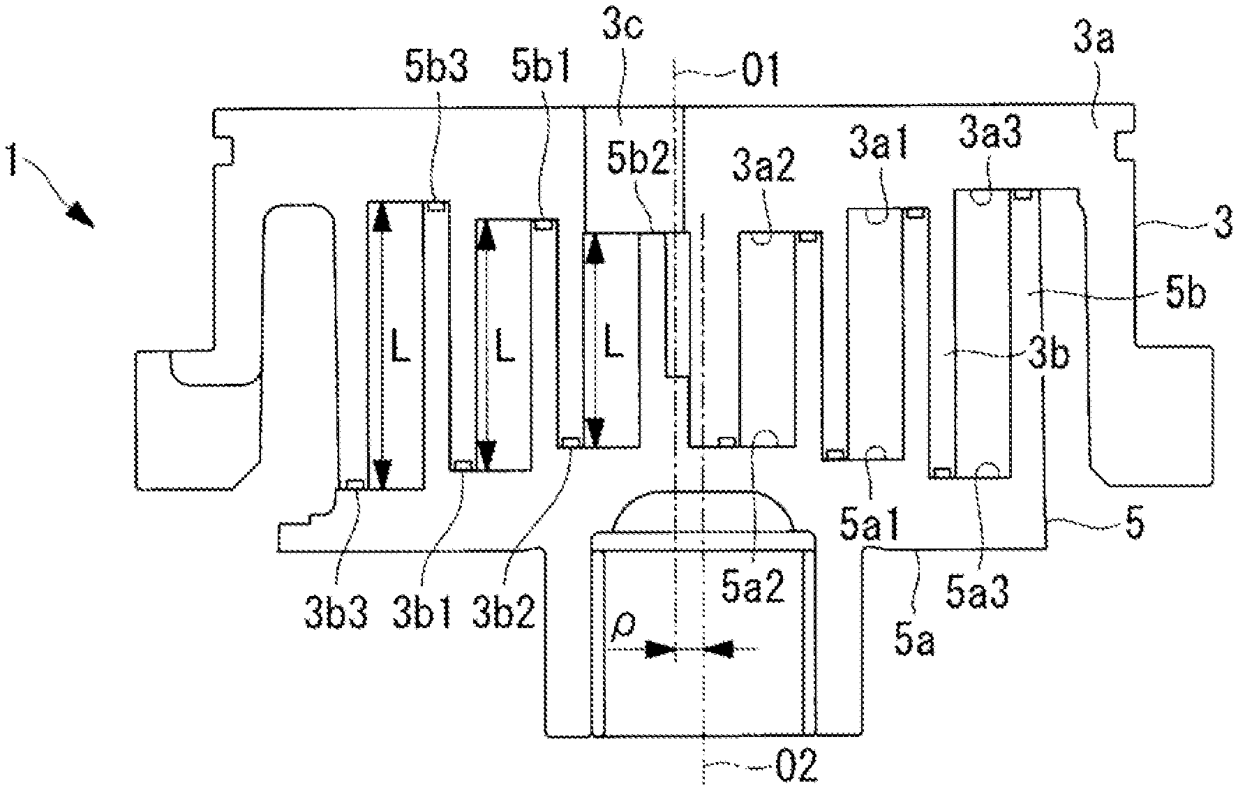
FIGS. 1A and 1B illustrate a fixed scroll and an orbiting scroll of a scroll compressor according to an embodiment of the present invention; FIG. 1A is a longitudinal sectional view, and FIG. 1B is a plan view as viewed from the wall side of the fixed scroll.
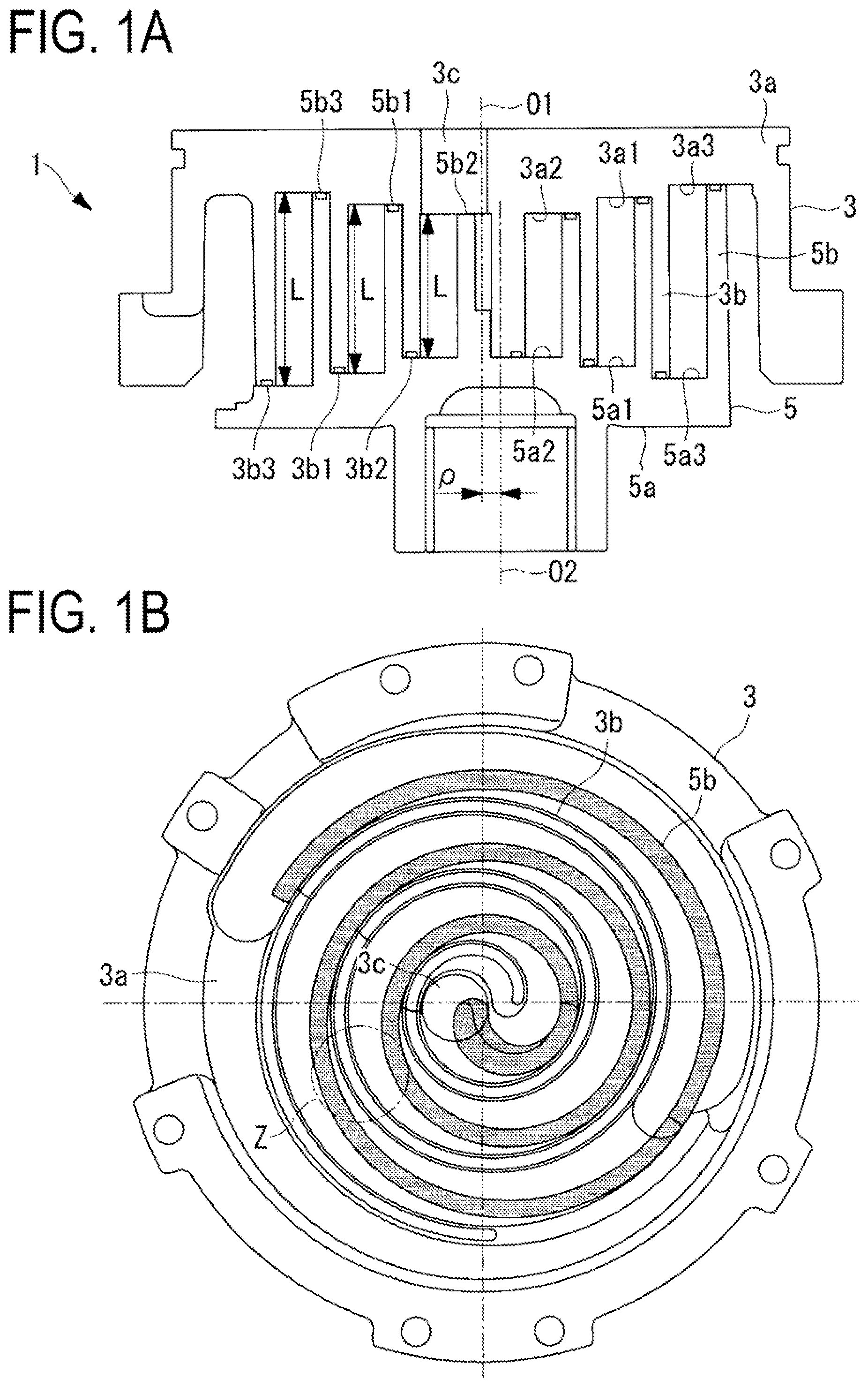
FIG. 2 is a perspective view illustrating the orbiting scroll illustrated in FIGS. 1A and 1B.
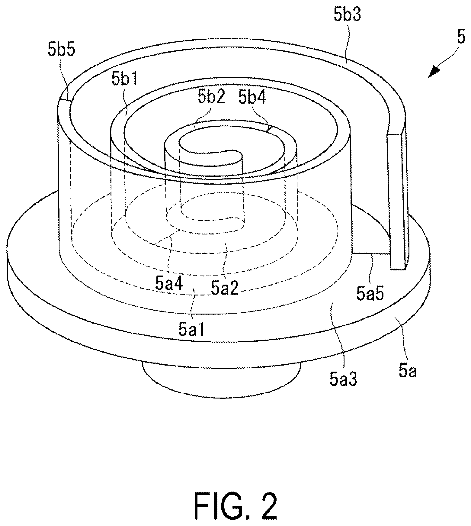
FIG. 3 is a plan view illustrating an end plate flat portion provided in the fixed scroll.
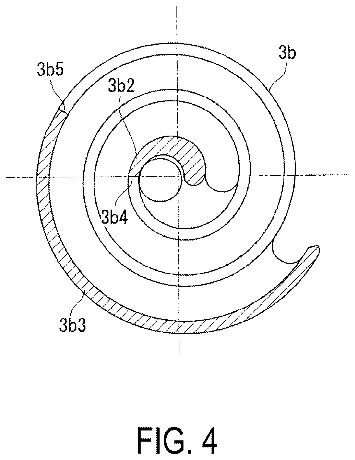
FIG. 4 is a plan view illustrating a wall flat portion provided in the fixed scroll.
FIG. 5 is a schematic view illustrating a wall unrolled in the spiral direction.
FIG. 6 is a partially enlarged view of the region indicated with reference sign Z in FIG. 1B.
FIGS. 7A and 7B illustrate a tip seal gap of the portion illustrated in FIG. 6; FIG. 7A is a side view illustrating a state where the tip seal gap is relatively small, and FIG. 7B is a side view illustrating a state where the tip seal gap is relatively large.
FIG. 8 is a longitudinal sectional view illustrating an installation position of the tip seal provided in the tooth crest of the wall in a non-load state.
FIGS. 9A and 9B illustrate a modification; FIG. 9A is a longitudinal sectional view illustrating a combination with a scroll provided with no step, and FIG. 9B is a longitudinal sectional view illustrating a combination with a stepped scroll.
DESCRIPTION OF EMBODIMENTS
Embodiments of the present invention will be described below with reference to the drawings.
FIGS. 1A and 1B illustrates a fixed scroll (first scroll member) 3 and an orbiting scroll (second scroll member) 5 of a scroll compressor (scroll fluid machine) 1. The scroll compressor 1 is used as a compressor that compresses gas refrigerant (fluid) for performing refrigeration cycle of an air conditioner or the like, for example.
The fixed scroll 3 and the orbiting scroll 5 are compression mechanisms made of metal such as aluminum alloy and iron, and are housed in a housing not illustrated. The fixed scroll 3 and the orbiting scroll 5 suck, from the outer peripheral side, fluid guided into the housing, and discharge compressed fluid from a discharge port 3c located at the center of the fixed scroll 3.
The fixed scroll 3 is fixed to the housing, and includes a substantially disk-plate-shaped end plate (first end plate) 3a, and a spiral-shaped wall (first wall) 3b disposed upright on one side surface of the end plate 3a as illustrated in FIG. 1A. The orbiting scroll 5 includes a substantially disk-plate-shaped end plate (second end plate) 5a, and a spiral-shaped wall (second wall) 5b disposed upright on one side surface of the end plate 5a. The spiral shapes of the walls 3b and 5b are defined by involute, Archimedean spiral or the like, for example.
The fixed scroll 3 and the orbiting scroll 5 are engaged with each other such that the centers thereof are separated from each other by an orbit radius p and that the phases of the walls 3b and 5b are shifted by 180.degree., and fixed scroll 3 and the orbiting scroll 5 are mounted such that a slight clearance (tip clearance) in the height direction is provided between the tooth crest and the tooth base of the walls 3b and 5b of the scrolls at normal temperature. With this configuration, multiple pairs of compression chambers that are defined by the surrounding end plates 3a and 5a and the walls 3b and 5b and are symmetric about the scroll center are formed between the scrolls 3 and 5. With a rotation prevention mechanism such as an Oldham ring not illustrated, the orbiting scroll 5 rotates in orbital motion around the fixed scroll 3.
As illustrated in FIG. 1A, an inclined portion, in which a distance L between opposing surfaces of the end plates 3a and 5a facing each other gradually decreases from the outer peripheral side toward the inner peripheral side of the spiral-shaped walls 3b and 5b, is provided.
As illustrated in FIG. 2, the wall 5b of the orbiting scroll 5 is provided with a wall inclined portion 5b1 whose height gradually decreases from the outer peripheral side toward the inner peripheral side. An end plate inclined portion 3a1 (see FIG. 1A) that is inclined in accordance with the inclination of the wall inclined portion 5b1 is provided in the tooth base surface of the fixed scroll 3 that faces the tooth crest of the wall inclined portion 5b1. With the wall inclined portion 5b1 and the end plate inclined portion 3a1, a continuous inclined portion is defined. Likewise, the wall 3b of the fixed scroll 3 is provided with a wall inclined portion 3b1 whose height is gradually inclined from the outer peripheral side toward the inner peripheral side, and an end plate inclined portion 5a1 that faces the tooth crest of the wall inclined portion 3b1 is provided in the end plate 5a of the orbiting scroll 5.
It is to be noted that the term "gradually" in the inclined portion in the present embodiment is not limited to a smooth inclination, and may include a form that is visually recognized as being gradually inclined as viewed in the entire inclined portion in which small steps inevitably resulting from working processes are connected together stepwise. It should be noted that large steps such as a so-called stepped scroll is not included.
A coating is provided on the wall inclined portions 3b1 and 5b1 and/or the end plate inclined portions 3a1 and 5a1. Examples of the coating include manganese phosphate treatment, nickel phosphor plating, and the like.
As illustrated in FIG. 2, wall flat portions 5b2 and 5b3, each of which has a constant height, are provided on the innermost peripheral side and the outermost peripheral side, respectively, of the wall 5b of the orbiting scroll 5. The wall flat portions 5b2 and 5b3 are provided in a region of 180.degree. around center O2 of the orbiting scroll 5 (see FIG. 1A). Wall inclined connecting portions 5b4 and 5b5, which serve as bent portions, are provided at portions connecting between the wall inclined portion 5b1 and the wall flat portions 5b2 and 5b3, respectively.
Likewise, the tooth base of the end plate 5a of the orbiting scroll 5 is provided with end plate flat portions 5a2 and 5a3, each of which has a constant height. Likewise, the end plate flat portions 5a2 and 5a3 are provided in a region of 180.degree. around the center of the orbiting scroll 5. End plate inclined connecting portions 5a4 and 5a5, which serve as bent portions, are provided at portions connecting between the end plate inclined portion 5a1 and the end plate flat portions 5a2 and 5a3, respectively.
As illustrated with hatching in FIG. 3 and FIG. 4, the fixed scroll 3 includes end plate flat portions 3a2 and 3a3, wall flat portions 3b2 and 3b3, end plate inclined connecting portions 3a4 and 3a5 and wall inclined connecting portions 3b4 and 3b5 as with the orbiting scroll 5.
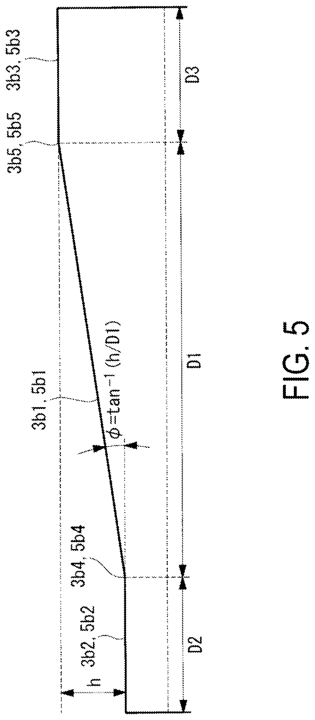
FIG. 5 illustrates the walls 3b and 5b unrolled in the spiral direction. As illustrated in the drawing, the wall flat portions 3b2 and 5b2 on the innermost peripheral side are provided over a distance D2, and the wall flat portions 3b3 and 5b3 on the outermost peripheral side are provided over a distance D3. The distance D2 and the distance D3 correspond to the regions of 180.degree. of the scrolls 3 and 5 around centers O1 and O2. The wall inclined portions 3b1 and 5b1 are provided over the distance D2 between the wall flat portions 3b2 and 5b2 on the innermost peripheral side and the wall flat portions 3b3 and 5b3 on the outermost peripheral side. When a height difference between the wall flat portions 3b2 and 5b2 on the innermost peripheral side and the wall flat portions 3b3 and 5b3 on the outermost peripheral side is represented by h, an inclination .phi. of the wall inclined portions 3b1 and 5b1 is expressed as follows. .phi.=tan.sup.-1(h/D1) (1)
In this manner, the inclination .phi. of the inclined portion is constant with respect to the circumferential direction in which the walls 3b and 5b having the spiral shape extend.
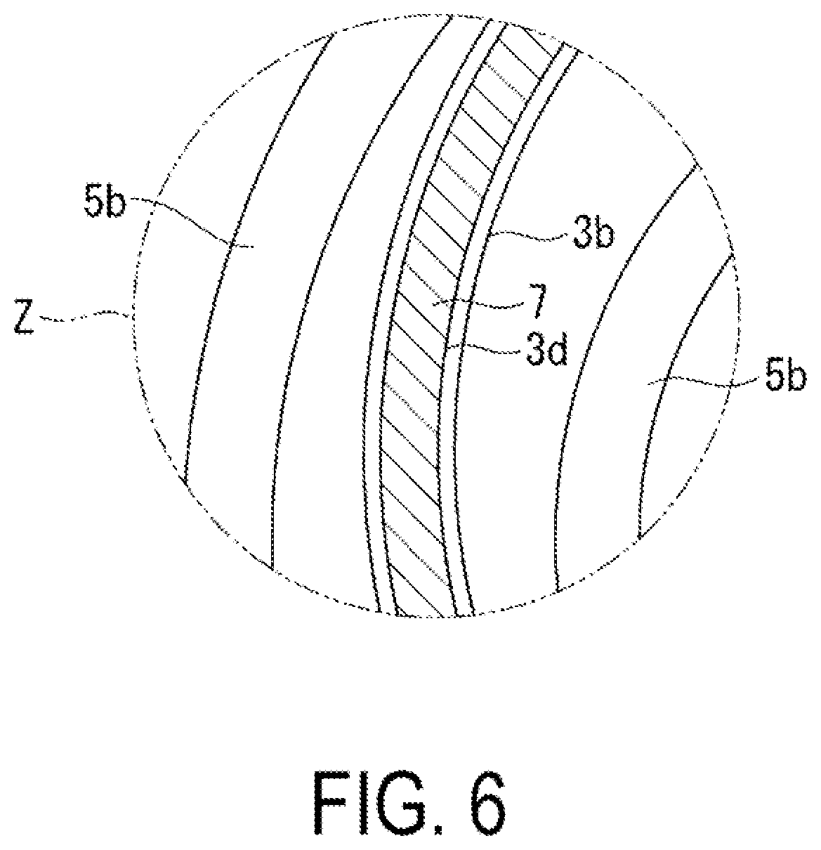
FIG. 6 illustrates an enlarged view of the region indicated by reference sign Z in FIG. 1B. As illustrated in FIG. 6, a tip seal 7 is provided in the tooth crest of the wall 3b of the fixed scroll 3. The tip seal 7 is made of elastically deformable resin, and makes contact with the opposing tooth base of the end plate 5a of the orbiting scroll 5 to perform sealing against fluid. The tip seal 7 is housed in a tip seal groove (groove portion) 3d formed in the tooth crest of the wall 3b over the circumferential direction.
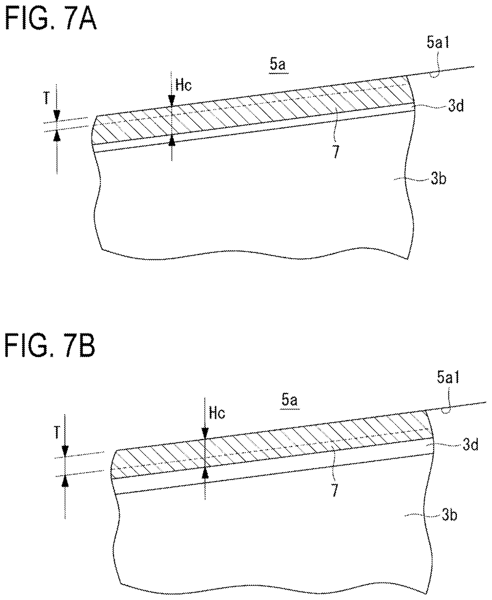
As illustrated in FIGS. 7A and 7B, a height Hc of the tip seal 7 in the height direction of the wall 3b is constant in the spiral direction. Also, the depth of the tip seal groove 3d is constant in the spiral direction.
When the scrolls 3 and 5 perform relative rotation in orbital motion, the positions of the tooth crest and the tooth base are relatively shifted by an orbit diameter (the orbit radius .rho..times.2). In the inclined portion, the tip clearance between the tooth crest and the tooth base varies in response to the positional displacement of the tooth crest and the tooth base. For example, FIG. 7A illustrates a small tip clearance T, and FIG. 7B illustrates a large tip clearance T. Even when the tip clearance T is varied by an orbital motion, the tip seal 7 is pressed from the back surface toward the tooth base of the end plate 5a by compression fluid which has entered the tip seal groove 3d, and thus can follow up and perform sealing.
It is to be noted that the tip seal is provided also in the tooth crest of the wall 5b of the orbiting scroll 5.
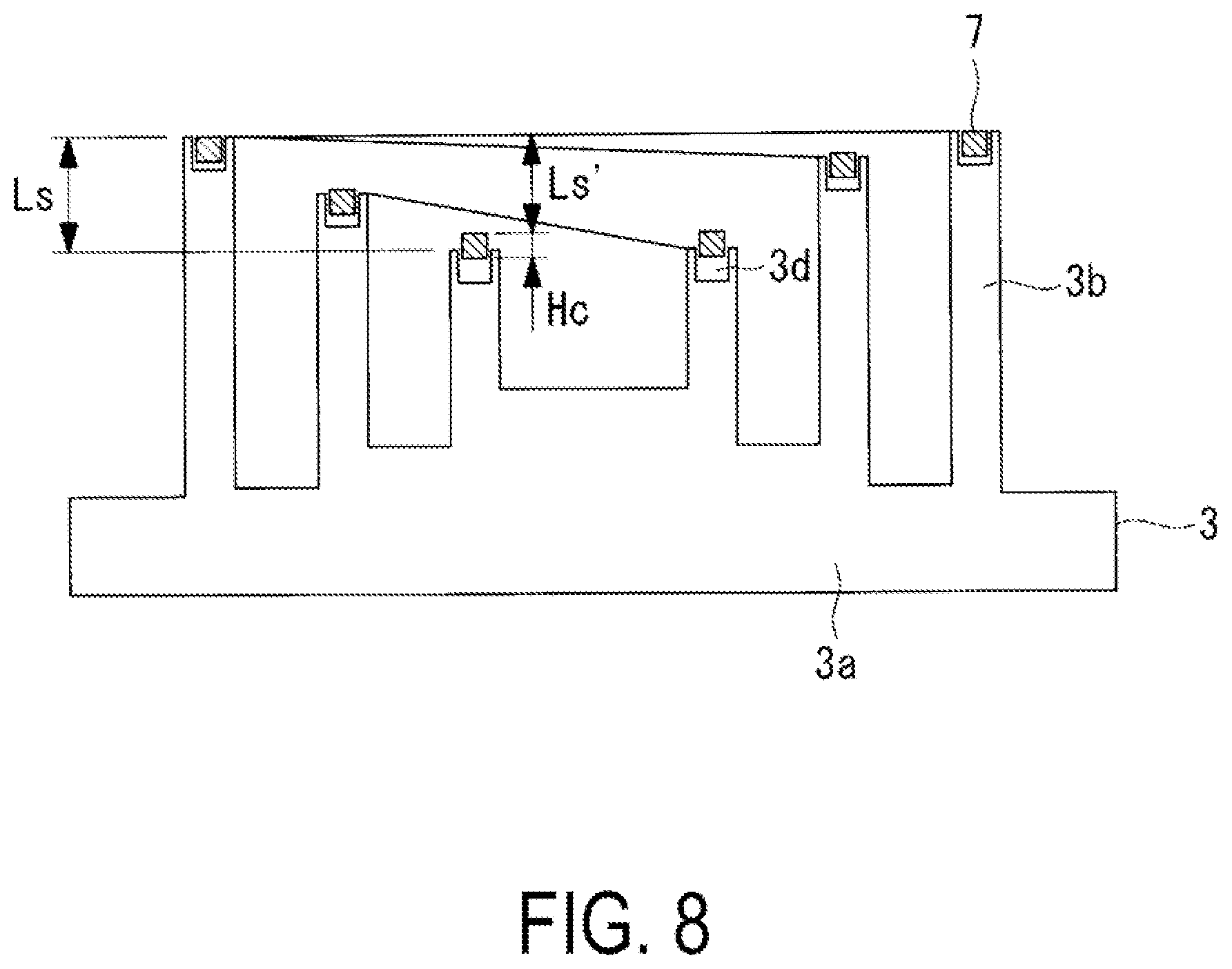
FIG. 8 illustrates a state where the tip seal 7 is installed in the fixed scroll 3. The state illustrated in this drawing is a non-load state where no pressure of compression fluid is exerted on the compression chamber, that is, a stop state of the scroll compressor 1. In addition, this state corresponds to a state before the fixed scroll 3 is engaged with the orbiting scroll 5 and mounted to the main body of the scroll compressor 1 in manufacture of the scroll compressor 1.
The inclination height Ls' of the tip seal 7 is set to a value smaller than that of the inclination height Ls of the wall 3b. Here, the inclination height Ls' of the tip seal 7 is a difference between the height of a position in the tip seal 7 which corresponds to the wall inclined connecting portion 3b5 (see FIG. 5) located on the outer peripheral side in the wall 3b, and the height of a position in the tip seal 7 which corresponds to the wall inclined connecting portion 3b4 (see FIG. 5) located on the inner peripheral side in the wall 3b. The inclination height Ls of the wall 3b is a difference between the height of the wall inclined connecting portion 3b5 on the outer peripheral side and the height of the wall inclined connecting portion 3b4 on the inner peripheral side.
To install the tip seal 7 as illustrated in FIG. 8, a flat tip seal 7 whose inclination height Ls' in the state where no external force is applied thereto is set to 0 is prepared. Then, the tip seal is installed in the tip seal groove 3d by utilizing elastic deformation of the tip seal 7 (tip seal installation step). When the outer peripheral surface and/or the inner peripheral surface of the tip seal 7 make contact with the wall portion of the tip seal groove 3d, a frictional force is generated and thus the relative position of the tip seal 7 with respect to the tip seal groove 3d is fixed. Accordingly, even in the case where the fixed scroll 3 is inclined or inverted when the fixed scroll 3 is mounted and installed (in a scroll installation step), the relative position of the tip seal 7 with respect to the tip seal groove 3d is not significantly shifted. It should be noted that the frictional force between the wall portion of the tip seal groove 3d and the outer peripheral surface and/or the inner peripheral surface of the tip seal 7 is set to a value that allows, when fluid enters the tip seal groove 3d and turns around the back surface of the tip seal 7 during operation of the scroll compressor 1, the tip seal 7 under the fluid pressure to move toward the opposing tooth base (in the direction in which the tip seal 7 goes out from the tip seal groove 3d).
The height Hc of the tip seal is greater than the difference between the inclination height Ls of the wall 3b and the inclination height Ls' of the tip seal 7. That is, the height Hc of the tip seal 7 is set to satisfy the following equation. Ls-Ls'.ltoreq.Hc (2)
In addition, the inclination height Ls' of the tip seal 7 is set also in the tooth crest of the wall 5b of the orbiting scroll 5 as in FIG. 8.
The above-described scroll compressor 1 operates in the following manner.
The orbiting scroll 5 is rotated in orbital motion around the fixed scroll 3 by a driving source such as an electric motor not illustrated. In this manner, fluid is sucked from the outer peripheral side of the scrolls 3 and 5, and the fluid is taken into the compression chamber surrounded by the walls 3b and 5b and the end plates 3a and 5a. The fluid in compression chamber is compressed as it moves from the outer peripheral side toward the inner peripheral side, and finally compressed fluid is discharged from the discharge port 3c formed in the fixed scroll 3. When the fluid is compressed, the fluid is compressed also in the height direction of the walls 3b and 5b in the inclined portion defined by the end plate inclined portions 3a1 and 5a1 and the wall inclined portions 3b1 and 5b1, and thus three-dimensional compression is performed.
According to the present embodiment, the following effects are achieved.
The inclination height Ls' of the tip seal 7 in a stop state where compression of fluid by the scrolls 3 and 5 is not performed is set to a value smaller than that of the inclination height of the walls 3b and 5b. With this configuration, the tip seal 7 is installed such that the tip seal 7 protrudes from the tooth crest to the tooth base side more on the inner periphery side than on the outer peripheral side in the stop state (see FIG. 8). Since the tip seal 7 protrudes to the tooth base side more on the inner periphery side than on the outer peripheral side, the fluid enters, more easily on the inner peripheral side than on the outer peripheral side, the tip seal groove 3d in which the tip seal 7 is inserted. When an operation is started from the stop state and the compression of the fluid is performed by the scrolls 3 and 5, the compressed fluid enters the tip seal groove 3d of the inner periphery side of the tip seal 7, and biases the tip seal 7 toward the tooth base from the back surface of the tip seal 7. Accordingly, the pressing forth of the tip seal 7 against the tooth base is larger on the inner periphery side where the fluid pressure is high during operation, and thus a high sealing performance can be achieved, improving the performance of the scroll compressor 1.
Since the height Hc of the tip seal is greater than the difference between the inclination height Ls' of the tip seal 7 and the inclination height Ls of the walls 3b and 5b (see the expression (2)), the tip seal 7 can be prevented from dropping off from the tip seal groove 3d.
When the tip seal 7 is made of a material such as an elastically deformable resin, the tip seal 7 can be installed by utilizing elastic deformation. That is, the tip seal 7 can be installed in the tip seal groove 3d so as to be elastically deformed such that the inclination height Ls' of the tip seal 7 is smaller than the inclination height Ls of the walls 3b and 5b in the stop state. As a result, it is unnecessary to form the tip seal 7 in a shape inclined in the height direction, and therefore, by manufacturing flat tip seal 7 that has no inclination when no external force is applied thereto, the ease of manufacture and inspection of the tip seal 7 increases.
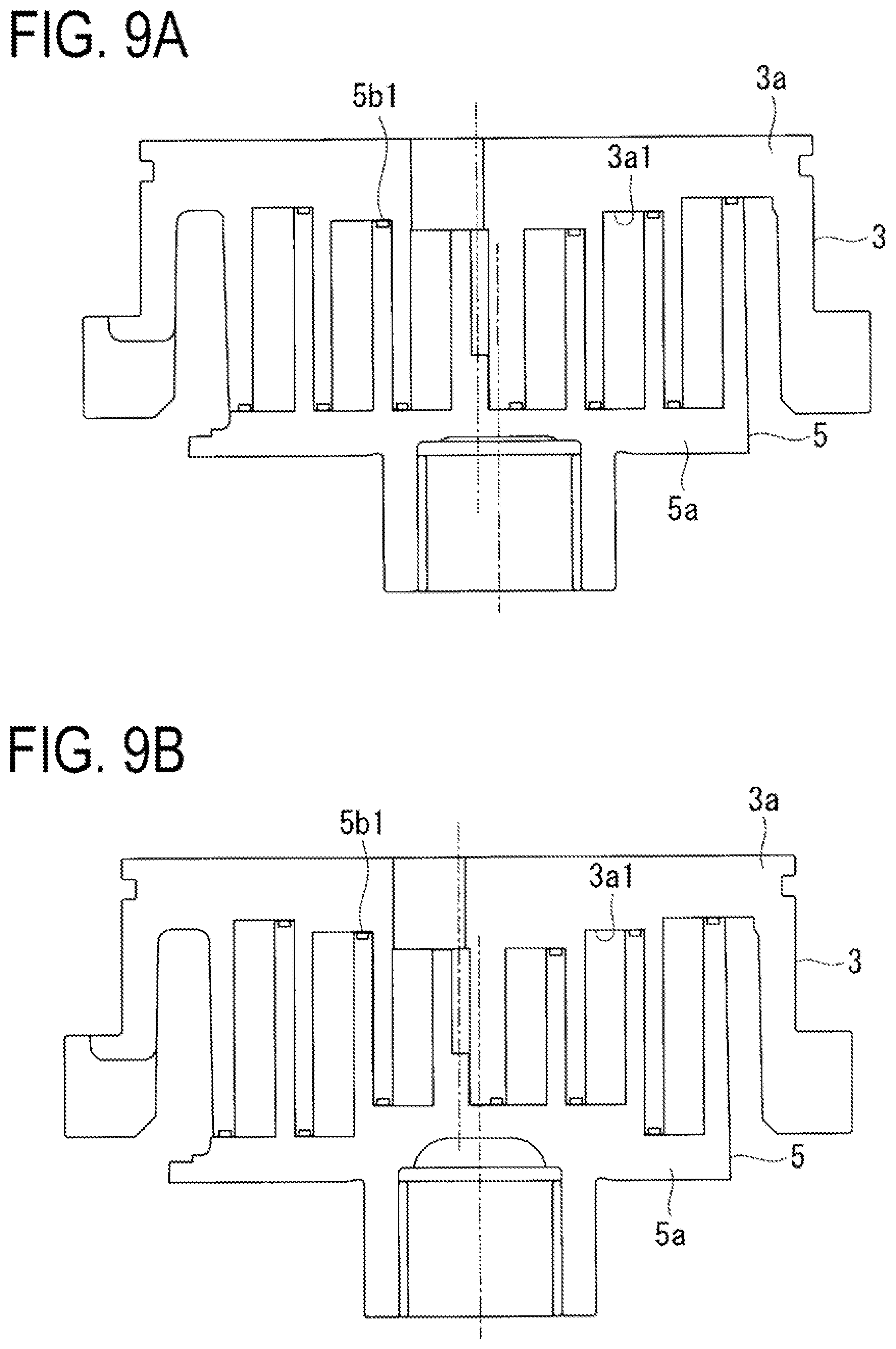
In addition, while the end plate inclined portions 3a1 and 5a1 and the wall inclined portions 3b1 and 5b1 are provided in the scrolls 3 and 5 in the above-mentioned embodiment, the end plate inclined portion and the wall inclined portion may be provided in only one of the scrolls 3 and 5.
To be more specific, in the case where the wall inclined portion 5b1 is provided in the wall of one scroll (the orbiting scroll 5, for example) and the end plate inclined portion 3a1 is provided in the end of plate 3a of the other scroll as illustrated in FIG. 9A, the wall of the other scroll and the end plate 5a of the one scroll may be flat.
In addition, as illustrated in FIG. 9B, it is possible to adopt a shape combined with a stepped shape of the related art, that is, a shape combined with a shape in which the end plate inclined portion 3a1 is provided in the end plate 3a of the fixed scroll 3 and a step is provided in the end plate 5a of the orbiting scroll 5.
While the wall flat portions 3b2 3b3, 5b2 and 5b3 and the end plate flat portions 3a2 3a3, 5a2 and 5a3 are provided in the above-mentioned embodiment, the flat portion of the inner peripheral side and/or the outer peripheral side may be omitted so as to extend the inclined portion in the entirety of the walls 3b and 5b.
While a scroll compressor is described in the above-mentioned embodiment, the present invention is applicable to a scroll expander used as an expander.
REFERENCE SIGNS LIST
1 Scroll Compressor (Scroll Fluid Machine) 3 Fixed Scroll (First Scroll Member) 3a End Plate (First End Plate) 3a1 End Plate Inclined Portion 3a2 End Plate Flat Portion (Inner Peripheral Side) 3a3 End Plate Flat Portion (Outer Peripheral Side) 3a4 End Plate Inclined Connecting Portion (Inner Peripheral Side) 3a5 End Plate Inclined Connecting Portion (Outer Peripheral Side) 3b Wall (First Wall) 3b1 Wall Inclined Portion 3b2 Wall Flat Portion (Inner Peripheral Side) 3b3 Wall Flat Portion (Outer Peripheral Side) 3b4 Wall Inclined Connecting Portion (Inner Peripheral Side) 3b5 Wall Inclined Connecting Portion (Outer Peripheral Side) 3c Discharge port 3d Tip Seal Groove (Groove Portion) 5 Orbiting Scroll (Second Scroll Member) 5a End Plate (Second End Plate) 5a1 End Plate Inclined Portion 5a2 End Plate Flat Portion (Inner Peripheral Side) 5a3 End Plate Flat Portion (Outer Peripheral Side) 5b Wall (Second Wall) 5b1 Wall Inclined Portion 5b2 Wall Flat Portion (Inner Peripheral Side) 5b3 Wall Flat Portion (Outer Peripheral Side) 5b4 Wall Inclined Connecting Portion (Inner Peripheral Side) 5b5 Wall Inclined Connecting Portion (Outer Peripheral Side) 7 Tip Seal Hc Height of Tip Seal L Distance between Opposing Surfaces Ls Inclination Height of Wall Ls' Inclination Height of Tip Seal T Tip Clearance .PHI. Inclination
* * * * *
D00000
D00001
D00002
D00003
D00004
D00005
D00006
D00007
D00008
D00009
XML
uspto.report is an independent third-party trademark research tool that is not affiliated, endorsed, or sponsored by the United States Patent and Trademark Office (USPTO) or any other governmental organization. The information provided by uspto.report is based on publicly available data at the time of writing and is intended for informational purposes only.
While we strive to provide accurate and up-to-date information, we do not guarantee the accuracy, completeness, reliability, or suitability of the information displayed on this site. The use of this site is at your own risk. Any reliance you place on such information is therefore strictly at your own risk.
All official trademark data, including owner information, should be verified by visiting the official USPTO website at www.uspto.gov. This site is not intended to replace professional legal advice and should not be used as a substitute for consulting with a legal professional who is knowledgeable about trademark law.