Adjustable implant assembly
Gamache , et al. April 13, 2
U.S. patent number 10,973,556 [Application Number 12/140,412] was granted by the patent office on 2021-04-13 for adjustable implant assembly. This patent grant is currently assigned to DePuy Synthes Products, Inc.. The grantee listed for this patent is Kenneth Connell, Thomas Gamache, Michael Varieur. Invention is credited to Kenneth Connell, Thomas Gamache, Michael Varieur.


| United States Patent | 10,973,556 |
| Gamache , et al. | April 13, 2021 |
Adjustable implant assembly
Abstract
An implant assembly includes a screw body, including anchor portion and proximal head portion, and a cradle movably mounted in the screw body to allow for controlled angulation between a spinal connection element disposed in the cradle and the screw body. The cradle is pivotable in one or more selected directions about one or more axes relative to the screw body. The cradle may be generally, substantially spherical in shape and allow for unrestricted movement in one or more directions around one or more axis.
| Inventors: | Gamache; Thomas (Westport, MA), Varieur; Michael (Portsmouth, RI), Connell; Kenneth (Rumford, RI) | ||||||||||
|---|---|---|---|---|---|---|---|---|---|---|---|
| Applicant: |
|
||||||||||
| Assignee: | DePuy Synthes Products, Inc.
(Raynham, MA) |
||||||||||
| Family ID: | 1000005482605 | ||||||||||
| Appl. No.: | 12/140,412 | ||||||||||
| Filed: | June 17, 2008 |
Prior Publication Data
| Document Identifier | Publication Date | |
|---|---|---|
| US 20090312804 A1 | Dec 17, 2009 | |
| Current U.S. Class: | 1/1 |
| Current CPC Class: | A61B 17/704 (20130101); A61B 17/7032 (20130101) |
| Current International Class: | A61B 17/04 (20060101); A61B 17/86 (20060101); A61B 17/70 (20060101); A61F 2/08 (20060101); A61B 17/84 (20060101) |
| Field of Search: | ;606/308,266 |
References Cited [Referenced By]
U.S. Patent Documents
| 410780 | September 1889 | Cahn |
| 445513 | January 1891 | Powell |
| 1116532 | November 1914 | Armstrong |
| 1470313 | October 1923 | Woolen |
| 1628144 | May 1927 | Herrmann |
| 1709766 | April 1929 | Bolton |
| 1889330 | November 1932 | Humes et al. |
| 1925385 | September 1933 | Humes et al. |
| 2113246 | April 1938 | Frederick |
| 2248054 | July 1941 | Becker |
| 2248057 | July 1941 | Bond |
| 2291413 | July 1942 | Siebrandt |
| 2370407 | February 1945 | Howard |
| 2669896 | February 1954 | Clough |
| 2800820 | July 1957 | Retterath |
| 2952285 | September 1960 | Roosli |
| 3604487 | September 1971 | Gilbert |
| 3960147 | June 1976 | Murray |
| 4237875 | December 1980 | Termanini |
| 4271836 | June 1981 | Bacal et al. |
| 4363250 | December 1982 | Suga |
| 4411259 | October 1983 | Drummond |
| 4445513 | May 1984 | Ulrich et al. |
| 4655223 | April 1987 | Kim |
| 4733657 | March 1988 | Kluger |
| 4743260 | May 1988 | Burton |
| 4809695 | March 1989 | Gwathmey et al. |
| 4887596 | December 1989 | Sherman |
| 4896661 | January 1990 | Bogert et al. |
| 4950269 | August 1990 | Gaines, Jr. |
| 4957495 | September 1990 | Kluger et al. |
| 4987892 | January 1991 | Krag et al. |
| 5005562 | April 1991 | Cotrel et al. |
| 5014407 | May 1991 | Boughten et al. |
| 5020519 | June 1991 | Hayes et al. |
| 5067955 | November 1991 | Cotrel |
| 5092866 | March 1992 | Breard et al. |
| 5120171 | June 1992 | Lasner |
| 5176678 | January 1993 | Tsou |
| 5176680 | January 1993 | Vignaud et al. |
| 5181917 | January 1993 | Rogozinski |
| 5181971 | January 1993 | Ohtsuka |
| 5190543 | March 1993 | Schlapfer |
| 5219349 | June 1993 | Krag et al. |
| 5226766 | July 1993 | Lasner |
| 5261913 | November 1993 | Marnay |
| 5263939 | November 1993 | Wortrich |
| 5282801 | February 1994 | Sherman |
| 5282863 | February 1994 | Burton |
| D346217 | April 1994 | Sparker et al. |
| 5306248 | April 1994 | Barrington |
| 5330474 | July 1994 | Lin |
| 5334203 | August 1994 | Wagner |
| 5360431 | November 1994 | Puno et al. |
| 5364397 | November 1994 | Hayes et al. |
| 5385565 | January 1995 | Ray |
| 5387213 | February 1995 | Breard et al. |
| 5391170 | February 1995 | McGuire et al. |
| 5415661 | May 1995 | Holmes |
| 5429641 | July 1995 | Goffried |
| 5431658 | July 1995 | Moskovich |
| 5468241 | November 1995 | Metz-Stavenhagen et al. |
| 5478340 | December 1995 | Kluger |
| 5484440 | January 1996 | Allard |
| 5487744 | January 1996 | Howland |
| 5499983 | March 1996 | Hughes |
| 5501684 | March 1996 | Schlapfer et al. |
| 5520689 | May 1996 | Schlapfer et al. |
| 5522816 | June 1996 | Dinello et al. |
| 5536127 | July 1996 | Pennig |
| 5536268 | July 1996 | Griss |
| 5540688 | July 1996 | Navas |
| 5545165 | August 1996 | Biedermann et al. |
| 5549608 | August 1996 | Errico et al. |
| 5551320 | September 1996 | Horobec et al. |
| 5591166 | January 1997 | Bernhardt et al. |
| 5591235 | January 1997 | Kuslich |
| 5616143 | April 1997 | Schlapfer et al. |
| 5649931 | July 1997 | Bryant et al. |
| 5667513 | September 1997 | Torrie et al. |
| 5672175 | September 1997 | Martin |
| 5672176 | September 1997 | Biedermann et al. |
| 5683399 | November 1997 | Jones |
| 5697933 | December 1997 | Gundlapalli et al. |
| 5702393 | December 1997 | Pfaifer |
| 5707371 | January 1998 | Metz-Stavenhagen |
| 5720751 | February 1998 | Jackson |
| 5725532 | March 1998 | Shoemaker |
| 5746757 | May 1998 | McGuire |
| 5782831 | July 1998 | Sherman et al. |
| 5797910 | August 1998 | Martin |
| 5797911 | August 1998 | Sherman et al. |
| 5810878 | September 1998 | Burel et al. |
| 5814046 | September 1998 | Hopf |
| 5879350 | March 1999 | Sherman et al. |
| 5882350 | March 1999 | Ralph et al. |
| 5885285 | March 1999 | Simonson |
| RE36211 | May 1999 | Nonomura |
| RE36221 | June 1999 | Breard et al. |
| 5910141 | June 1999 | Morrison et al. |
| 5938663 | August 1999 | Petreto |
| 5941885 | August 1999 | Jackson |
| 5951555 | September 1999 | Rehak et al. |
| 5951564 | September 1999 | Schroder et al. |
| 5951579 | September 1999 | Dykes |
| 5964760 | October 1999 | Richelsoph |
| 5976133 | November 1999 | Kraus et al. |
| 5989250 | November 1999 | Wagner et al. |
| 5989254 | November 1999 | Katz |
| 6010509 | January 2000 | Delgado et al. |
| 6036692 | March 2000 | Burel et al. |
| 6050997 | April 2000 | Mullane |
| 6063090 | May 2000 | Schlapfer |
| 6073491 | June 2000 | Fischer et al. |
| 6074391 | June 2000 | Metz-Stavenhagen et al. |
| 6090110 | July 2000 | Metz-Stavenhagen |
| 6090113 | July 2000 | Le Couedic et al. |
| 6099528 | August 2000 | Saurat |
| 6123707 | September 2000 | Wagner |
| 6139549 | October 2000 | Keller |
| 6146383 | November 2000 | Studer et al. |
| 6183472 | February 2001 | Lutz |
| 6189422 | February 2001 | Stihl |
| 6204060 | March 2001 | Mehtali et al. |
| 6210330 | April 2001 | Tepper |
| 6235028 | May 2001 | Brumfield et al. |
| 6251112 | June 2001 | Jackson |
| 6254602 | July 2001 | Justis |
| 6258090 | July 2001 | Jackson |
| 6261287 | July 2001 | Metz-Stavenhagen |
| 6280442 | August 2001 | Barker et al. |
| 6280443 | August 2001 | Gu et al. |
| 6287309 | September 2001 | Baccelli et al. |
| 6299616 | October 2001 | Beger |
| 6302888 | October 2001 | Mellinger et al. |
| 6309389 | October 2001 | Baccelli |
| 6368321 | April 2002 | Jackson |
| 6371973 | April 2002 | Tepper |
| 6379357 | April 2002 | Bernstein et al. |
| 6402752 | June 2002 | Schaffler-Wachter et al. |
| 6423065 | July 2002 | Ferree |
| 6440133 | August 2002 | Beale et al. |
| 6440137 | August 2002 | Horvath et al. |
| 6440142 | August 2002 | Ralph et al. |
| 6440144 | August 2002 | Bacher |
| 6443953 | September 2002 | Perra et al. |
| 6478798 | November 2002 | Howland |
| 6511484 | January 2003 | Torode et al. |
| 6530929 | March 2003 | Justis et al. |
| 6537276 | March 2003 | Metz-Stavenhagen |
| 6540748 | April 2003 | Lombardo |
| 6554831 | April 2003 | Rivard et al. |
| 6565567 | May 2003 | Haider |
| 6589249 | July 2003 | Sater et al. |
| 6597279 | July 2003 | Haraguchi |
| 6623485 | September 2003 | Doubler et al. |
| 6648888 | November 2003 | Shluzas |
| 6652523 | November 2003 | Evrard et al. |
| 6660006 | December 2003 | Markworth et al. |
| 6689137 | February 2004 | Reed |
| 6692500 | February 2004 | Reed |
| 6695843 | February 2004 | Biedermann et al. |
| 6716214 | April 2004 | Jackson |
| 6726692 | April 2004 | Bette et al. |
| 6733502 | May 2004 | Altarac et al. |
| 6743231 | June 2004 | Gray et al. |
| 6746449 | June 2004 | Jones et al. |
| 6749613 | June 2004 | Conchy et al. |
| 6752832 | June 2004 | Neumann |
| 6755829 | June 2004 | Bono et al. |
| 6783527 | August 2004 | Drewry et al. |
| 6790208 | September 2004 | Oribe et al. |
| 6790209 | September 2004 | Beale et al. |
| 6800078 | October 2004 | Reed |
| 6800079 | October 2004 | Reed |
| 6827722 | December 2004 | Schoenefeld |
| 6837889 | January 2005 | Shluzas |
| 6964666 | November 2005 | Jackson |
| 7081117 | July 2006 | Bono et al. |
| 7083621 | August 2006 | Shaolian et al. |
| 7090677 | August 2006 | Fallin et al. |
| 7156849 | January 2007 | Dunbar et al. |
| 7160300 | January 2007 | Jackson |
| 7179254 | February 2007 | Pendekanti et al. |
| 7179261 | February 2007 | Sicvol et al. |
| 7189234 | March 2007 | Zucherman et al. |
| 7250052 | July 2007 | Landry et al. |
| 7278995 | October 2007 | Nichols et al. |
| 7320689 | January 2008 | Keller |
| 7322979 | January 2008 | Crandall et al. |
| 7371239 | May 2008 | Dec et al. |
| 7455685 | November 2008 | Justis |
| 7462182 | December 2008 | Lim |
| 7465306 | December 2008 | Pond, Jr. et al. |
| 7470279 | December 2008 | Jackson |
| 7485120 | February 2009 | Ray |
| 7491207 | February 2009 | Keyer et al. |
| 7491208 | February 2009 | Pond, Jr. et al. |
| 7491218 | February 2009 | Landry et al. |
| 7527638 | May 2009 | Anderson et al. |
| 7572281 | August 2009 | Runco et al. |
| 7588585 | September 2009 | Gold et al. |
| 7591836 | September 2009 | Dick et al. |
| 7621918 | November 2009 | Jackson |
| 7651502 | January 2010 | Jackson |
| 7666188 | February 2010 | Anderson et al. |
| 7666189 | February 2010 | Gerber et al. |
| 7708736 | May 2010 | Mullaney |
| 7708763 | May 2010 | Selover et al. |
| 7766944 | August 2010 | Metz-Stavenhagen |
| 7794464 | September 2010 | Bridwell et al. |
| 7824411 | November 2010 | Varieur et al. |
| 7824413 | November 2010 | Varieur et al. |
| 7842044 | November 2010 | Runco et al. |
| 7867237 | January 2011 | Stad et al. |
| 7887539 | February 2011 | Dunbar, Jr. et al. |
| 7887541 | February 2011 | Runco et al. |
| 7951168 | May 2011 | Chao et al. |
| 7951172 | May 2011 | Chao et al. |
| 7951175 | May 2011 | Chao et al. |
| 7988698 | August 2011 | Rosenberg et al. |
| 8007516 | August 2011 | Chao et al. |
| 8172847 | May 2012 | Dziedzic et al. |
| 8192438 | June 2012 | Garamszegi |
| 8216241 | July 2012 | Runco et al. |
| 8608746 | December 2013 | Kolb et al. |
| 8647347 | February 2014 | Runco et al. |
| 8709044 | April 2014 | Chao et al. |
| 8845700 | September 2014 | Kwak et al. |
| 8888777 | November 2014 | Mullaney |
| 9095379 | August 2015 | Chao et al. |
| 9795416 | October 2017 | Chao et al. |
| 10172648 | January 2019 | Chao et al. |
| 10314624 | June 2019 | Chao et al. |
| 2001/0020169 | September 2001 | Metz-Stavenhagen |
| 2001/0029376 | October 2001 | Saler et al. |
| 2002/0035366 | March 2002 | Walder et al. |
| 2002/0072752 | June 2002 | Zucherman et al. |
| 2002/0082599 | June 2002 | Crandall et al. |
| 2002/0095153 | July 2002 | Jones et al. |
| 2002/0133155 | September 2002 | Ferree |
| 2002/0143341 | October 2002 | Biedermann et al. |
| 2002/0151900 | October 2002 | Glascott |
| 2002/0173789 | November 2002 | Howland |
| 2003/0009168 | January 2003 | Beale et al. |
| 2003/0028195 | February 2003 | Bette |
| 2003/0045875 | March 2003 | Bertranou et al. |
| 2003/0073995 | April 2003 | Reed |
| 2003/0083657 | May 2003 | Drewry et al. |
| 2003/0083747 | May 2003 | Winterbottom et al. |
| 2003/0088248 | May 2003 | Reed |
| 2003/0100896 | May 2003 | Biedermann et al. |
| 2003/0105460 | June 2003 | Crandall et al. |
| 2003/0109880 | June 2003 | Shirado et al. |
| 2003/0114852 | June 2003 | Biedermann et al. |
| 2003/0125750 | July 2003 | Zwimmann et al. |
| 2003/0149438 | August 2003 | Nichols et al. |
| 2003/0171749 | September 2003 | Le Couedic et al. |
| 2003/0171756 | September 2003 | Fallin et al. |
| 2003/0176861 | September 2003 | Reed |
| 2003/0191370 | October 2003 | Phillips |
| 2003/0191470 | October 2003 | Ritland |
| 2003/0199872 | October 2003 | Markworth et al. |
| 2003/0203488 | October 2003 | Mehtali et al. |
| 2003/0220642 | November 2003 | Freudiger |
| 2003/0220643 | November 2003 | Ferree |
| 2003/0225408 | December 2003 | Nichols et al. |
| 2004/0002708 | January 2004 | Ritland |
| 2004/0049189 | March 2004 | Le Couedic et al. |
| 2004/0049190 | March 2004 | Biedermann et al. |
| 2004/0049191 | March 2004 | Markworth et al. |
| 2004/0073215 | April 2004 | Carli |
| 2004/0092931 | May 2004 | Taylor et al. |
| 2004/0102789 | May 2004 | Baughman |
| 2004/0147936 | July 2004 | Rosenberg et al. |
| 2004/0147937 | July 2004 | Dunbar et al. |
| 2004/0158257 | August 2004 | Bonati et al. |
| 2004/0158258 | August 2004 | Bonati et al. |
| 2004/0172025 | September 2004 | Drewry et al. |
| 2004/0172057 | September 2004 | Guillebon et al. |
| 2004/0176779 | September 2004 | Casutt et al. |
| 2004/0181224 | September 2004 | Biedermann et al. |
| 2004/0186473 | September 2004 | Cournoyer et al. |
| 2004/0204711 | October 2004 | Jackson |
| 2004/0220567 | November 2004 | Eisermann et al. |
| 2004/0225289 | November 2004 | Biedermann et al. |
| 2004/0243139 | December 2004 | Lewis et al. |
| 2004/0254576 | December 2004 | Dunbar et al. |
| 2004/0267260 | December 2004 | Mack et al. |
| 2004/0267264 | December 2004 | Konieczynski et al. |
| 2004/0267275 | December 2004 | Cournoyer et al. |
| 2005/0015094 | January 2005 | Keller |
| 2005/0015095 | January 2005 | Keller |
| 2005/0021031 | January 2005 | Foley et al. |
| 2005/0033291 | February 2005 | Ebara |
| 2005/0033295 | February 2005 | Wisnewski |
| 2005/0033299 | February 2005 | Shluzas |
| 2005/0055031 | March 2005 | Lim |
| 2005/0059969 | March 2005 | McKinley |
| 2005/0065514 | March 2005 | Studer |
| 2005/0065515 | March 2005 | Jahng |
| 2005/0065516 | March 2005 | Jahng |
| 2005/0065517 | March 2005 | Chin |
| 2005/0066514 | March 2005 | Chau et al. |
| 2005/0070917 | March 2005 | Justis |
| 2005/0079909 | April 2005 | Singhaseni |
| 2005/0085813 | April 2005 | Spitler et al. |
| 2005/0085815 | April 2005 | Harms et al. |
| 2005/0090824 | April 2005 | Shluzas et al. |
| 2005/0131408 | June 2005 | Sicvol et al. |
| 2005/0131420 | June 2005 | Techiera et al. |
| 2005/0131421 | June 2005 | Anderson et al. |
| 2005/0131422 | June 2005 | Anderson et al. |
| 2005/0137593 | June 2005 | Gray |
| 2005/0143737 | June 2005 | Pafford et al. |
| 2005/0143749 | June 2005 | Zalenski et al. |
| 2005/0149036 | July 2005 | Varieur et al. |
| 2005/0149048 | July 2005 | Leport et al. |
| 2005/0149053 | July 2005 | Varieur et al. |
| 2005/0154389 | July 2005 | Selover et al. |
| 2005/0159650 | July 2005 | Raymond et al. |
| 2005/0177163 | August 2005 | Abdou |
| 2005/0192570 | September 2005 | Jackson |
| 2005/0192573 | September 2005 | Abdelgany et al. |
| 2005/0192579 | September 2005 | Jackson |
| 2005/0192589 | September 2005 | Raymond et al. |
| 2005/0222570 | October 2005 | Jackson |
| 2005/0228376 | October 2005 | Boomer et al. |
| 2005/0228380 | October 2005 | Moore |
| 2005/0228392 | October 2005 | Keyer et al. |
| 2005/0228400 | October 2005 | Chao et al. |
| 2005/0234449 | October 2005 | Aferzon |
| 2005/0245928 | November 2005 | Colleran et al. |
| 2005/0261687 | November 2005 | Garamszegi et al. |
| 2005/0261702 | November 2005 | Oribe et al. |
| 2005/0283244 | December 2005 | Gordon |
| 2005/0288668 | December 2005 | Brinkhaus |
| 2006/0009775 | January 2006 | Dec et al. |
| 2006/0025768 | February 2006 | Iott et al. |
| 2006/0036254 | February 2006 | Lim |
| 2006/0036255 | February 2006 | Pond et al. |
| 2006/0036260 | February 2006 | Runco et al. |
| 2006/0069391 | March 2006 | Jackson |
| 2006/0074418 | April 2006 | Jackson |
| 2006/0079909 | April 2006 | Runco et al. |
| 2006/0089651 | April 2006 | Trudeau et al. |
| 2006/0095035 | May 2006 | Jones et al. |
| 2006/0111712 | May 2006 | Jackson |
| 2006/0111713 | May 2006 | Jackson |
| 2006/0111730 | May 2006 | Play |
| 2006/0149236 | July 2006 | Barry |
| 2006/0155277 | July 2006 | Metz-Stavenhagen |
| 2006/0166534 | July 2006 | Brumfield et al. |
| 2006/0166535 | July 2006 | Brumfield et al. |
| 2006/0173454 | August 2006 | Spitler et al. |
| 2006/0195092 | August 2006 | Barry |
| 2006/0200131 | September 2006 | Chao et al. |
| 2006/0200132 | September 2006 | Chao et al. |
| 2006/0217735 | September 2006 | MacDonald et al. |
| 2006/0229605 | October 2006 | Olsen |
| 2006/0229614 | October 2006 | Foley et al. |
| 2006/0247630 | November 2006 | Iott et al. |
| 2006/0264934 | November 2006 | Fallin |
| 2006/0271050 | November 2006 | Piza Vallespir |
| 2006/0282073 | December 2006 | Simanovsky |
| 2006/0293690 | December 2006 | Abdelgany |
| 2006/0293692 | December 2006 | Whipple et al. |
| 2007/0078460 | April 2007 | Frigg |
| 2007/0093849 | April 2007 | Jones et al. |
| 2007/0100347 | May 2007 | Stad et al. |
| 2007/0118118 | May 2007 | Kwak et al. |
| 2007/0129731 | June 2007 | Sicvol et al. |
| 2007/0161994 | July 2007 | Lowery et al. |
| 2007/0161998 | July 2007 | Whipple |
| 2007/0162009 | July 2007 | Chao et al. |
| 2007/0162010 | July 2007 | Chao et al. |
| 2007/0167954 | July 2007 | Sicvol et al. |
| 2007/0173831 | July 2007 | Abdou |
| 2007/0185375 | August 2007 | Stad et al. |
| 2007/0191836 | August 2007 | Justis |
| 2007/0213715 | September 2007 | Bridwell et al. |
| 2007/0213716 | September 2007 | Lenke et al. |
| 2007/0213722 | September 2007 | Jones et al. |
| 2007/0231059 | October 2007 | Mullaney |
| 2007/0233079 | October 2007 | Fallin et al. |
| 2007/0233097 | October 2007 | Anderson et al. |
| 2007/0260261 | November 2007 | Runco et al. |
| 2007/0270880 | November 2007 | Lindemann et al. |
| 2007/0282337 | December 2007 | Garamszegi |
| 2008/0045956 | February 2008 | Songer et al. |
| 2008/0077134 | March 2008 | Dziedzic et al. |
| 2008/0077135 | March 2008 | Stad et al. |
| 2008/0086130 | April 2008 | Lake et al. |
| 2008/0161853 | July 2008 | Arnold et al. |
| 2008/0161863 | July 2008 | Arnold et al. |
| 2008/0172062 | July 2008 | Donahue et al. |
| 2008/0195159 | August 2008 | Kloss et al. |
| 2008/0243190 | October 2008 | Dziedzic et al. |
| 2008/0255574 | October 2008 | Dye |
| 2008/0288005 | November 2008 | Jackson |
| 2009/0005815 | January 2009 | Ely |
| 2009/0018541 | January 2009 | Lavi |
| 2009/0030419 | January 2009 | Runco et al. |
| 2009/0030420 | January 2009 | Runco et al. |
| 2009/0054902 | February 2009 | Mickiewicz et al. |
| 2009/0062857 | March 2009 | Ramsay et al. |
| 2009/0082811 | March 2009 | Stad et al. |
| 2009/0088764 | April 2009 | Stad et al. |
| 2009/0138056 | May 2009 | Anderson et al. |
| 2009/0143828 | June 2009 | Stad et al. |
| 2009/0228051 | September 2009 | Kolb et al. |
| 2009/0228053 | September 2009 | Kolb et al. |
| 2009/0281579 | November 2009 | Weaver et al. |
| 2010/0042155 | February 2010 | Biedermann |
| 2010/0063544 | March 2010 | Butler |
| 2010/0137915 | June 2010 | Anderson et al. |
| 2011/0034961 | February 2011 | Runco et al. |
| 2011/0034962 | February 2011 | Dunbar, Jr. et al. |
| 2011/0077689 | March 2011 | Mickiewicz et al. |
| 2011/0093022 | April 2011 | Runco et al. |
| 2011/0144695 | June 2011 | Rosenberg et al. |
| 2011/0196431 | August 2011 | Chao et al. |
| 2011/0282402 | November 2011 | Chao et al. |
| 2012/0253413 | October 2012 | Runco et al. |
| 2014/0188182 | July 2014 | Chao et al. |
| 2014/0277198 | September 2014 | Stad |
| 2015/0297268 | October 2015 | Chao et al. |
| 2017/0156765 | June 2017 | Chao et al. |
| 2018/0008319 | January 2018 | Chao et al. |
| 2019/0216509 | July 2019 | Chao et al. |
| 2019/0307492 | October 2019 | Chao et al. |
| 3923996 | Jan 1991 | DE | |||
| 9110203 | Nov 1991 | DE | |||
| 4107480 | Sep 1992 | DE | |||
| 4238339 | May 1994 | DE | |||
| 10005385 | Aug 2001 | DE | |||
| 10005386 | Aug 2001 | DE | |||
| 20207851 | Nov 2002 | DE | |||
| 0381588 | Aug 1990 | EP | |||
| 0441729 | Aug 1991 | EP | |||
| 0487895 | Jun 1992 | EP | |||
| 0558883 | Sep 1993 | EP | |||
| 0572790 | Dec 1993 | EP | |||
| 0592266 | Apr 1994 | EP | |||
| 328883 | Jul 1994 | EP | |||
| 0669109 | Aug 1995 | EP | |||
| 558883 | Jul 1997 | EP | |||
| 0880344 | Dec 1998 | EP | |||
| 0885598 | Dec 1998 | EP | |||
| 0948939 | Oct 1999 | EP | |||
| 0951246 | Oct 1999 | EP | |||
| 1023873 | Aug 2000 | EP | |||
| 1090595 | Apr 2001 | EP | |||
| 784693 | Oct 2001 | EP | |||
| 1295566 | Mar 2003 | EP | |||
| 1364622 | Nov 2003 | EP | |||
| 1574175 | Sep 2005 | EP | |||
| 2677242 | Dec 1992 | FR | |||
| 2680314 | Feb 1993 | FR | |||
| 2729291 | Jul 1996 | FR | |||
| 90/02527 | Mar 1990 | WO | |||
| 9621396 | Jul 1996 | WO | |||
| 98/22033 | May 1998 | WO | |||
| 98/25534 | Jun 1998 | WO | |||
| 99/44527 | Sep 1999 | WO | |||
| 01/45576 | Jun 2001 | WO | |||
| 02/07622 | Jan 2002 | WO | |||
| 02/102259 | Dec 2002 | WO | |||
| 03/007828 | Jan 2003 | WO | |||
| 03/032863 | Apr 2003 | WO | |||
| 03/049629 | Jun 2003 | WO | |||
| 03096915 | Nov 2003 | WO | |||
| 2004004549 | Jan 2004 | WO | |||
| 04/019755 | Mar 2004 | WO | |||
| 04/034916 | Apr 2004 | WO | |||
| 2005006948 | Jan 2005 | WO | |||
| 05/013839 | Feb 2005 | WO | |||
| 05/030065 | Apr 2005 | WO | |||
| 05/044117 | May 2005 | WO | |||
| 05/044123 | May 2005 | WO | |||
| 2005072081 | Aug 2005 | WO | |||
| 2006020443 | Feb 2006 | WO | |||
| 06/084443 | Aug 2006 | WO | |||
| 2007092797 | Aug 2007 | WO | |||
| 2007092870 | Aug 2007 | WO | |||
| 2007092876 | Aug 2007 | WO | |||
| 2007149426 | Dec 2007 | WO | |||
| 2008024937 | Feb 2008 | WO | |||
Other References
|
Wiltse, Leon L. et al., "History of Pedicle Screw Fixation of the Spine," Spine, State of the Art Reviews, vol. 6(1):1-10 (1992). cited by applicant . International Search Report and Written Opinion for Application No. PCT/US06/40621, dated May 18, 2007. cited by applicant . International Search Report for Application No. PCT/US06/40621, dated May 18, 2007. cited by applicant . International Search Report for Application No. PCT/US06/05811, dated Sep. 13, 2007. cited by applicant . European Office Action for Application No. 06736870, dated Dec. 18, 2009. cited by applicant . European Office Action for Application No. 06735464.7, dated Apr. 14, 2010. cited by applicant . European Office Action for Application No. 06735464.7, 4 pages, dated Feb. 10, 2012. cited by applicant . Sofamor Introducteur Contreur De Tige, Schematic Drawings, 7 pages, Jun. 1994. cited by applicant . International Search Report and Written Opinion issued in International Application No. PCT/US06/07619 dated Apr. 16, 2007, 3 pages. cited by applicant . U.S. Appl. No. 16/217,329, filed Dec. 12, 2018, Nam T. Chao. cited by applicant . U.S. Appl. No. 15/711,380, filed Sep. 21, 2017, Nam T. Chao. cited by applicant . U.S. Appl. No. 14/754,259, filed Jun. 29, 2015, Nam T. Chao. cited by applicant . U.S. Appl. No. 13/087,777, filed Apr. 15, 2011, Nam T. Chao. cited by applicant . U.S. Appl. No. 11/073,325, filed Mar. 4, 2005, Nam T. Chao. cited by applicant . U.S. Appl. No. 16/436,471, filed Jun. 10, 2019, Nam T. Chao. cited by applicant . U.S. Appl. No. 15/434,899, filed Feb. 16, 2017, Nam T. Chao. cited by applicant . U.S. Appl. No. 14/200,891, filed Mar. 7, 2014, Nam T. Chao. cited by applicant . U.S. Appl. No. 13/188,161, filed Jul. 21, 2011, Nam T. Chao. cited by applicant . U.S. Appl. No. 11/707,471, filed Feb. 16, 2007, Nam T. Chao. cited by applicant . U.S. Appl. No. 11/073,352, filed Mar. 4, 2005, Nam T. Chao. cited by applicant . U.S. Appl. No. 11/707,696, filed Feb. 16, 2007, Nam T. Chao. cited by applicant. |
Primary Examiner: Woznicki; Jacqueline
Attorney, Agent or Firm: Nelson Mullins Riley & Scarborough LLP Laurentano; Anthony A.
Claims
The invention claimed is:
1. An implant assembly comprising: a bone anchor having a distal shaft extending along a longitudinal axis configured to engage bone; a proximal head portion connected to the bone anchor wherein the proximal head portion is a closed-type screw head, wherein the longitudinal axis of the bone anchor aligns with a longitudinal axis extending through the proximal head portion, and the proximal head portion is integral with the bone anchor and includes a central bore; a cradle within the proximal head portion for receiving a spinal fixation element, wherein the cradle can move relative to the proximal head portion allowing the spinal fixation element to pivot relative to the head portion, wherein the cradle comprises a spherical body with a central bore for receiving the spinal fixation element, the body being formed by an upper element that is a half sphere in shape and a lower element that is a half sphere in shape, wherein the upper element and the lower element have interlocking surface configurations to assist in mating the upper element and lower element; and a locking mechanism for locking a position of the cradle in the central bore of the proximal head portion and for, in conjunction with side walls of the central bore, mating the upper element and the lower element of the cradle.
2. An implant assembly comprising: a bone anchor having a distal shaft extending along a longitudinal axis configured to engage bone; a proximal head portion connected to the bone anchor wherein the proximal head is a closed-type screw head, wherein the longitudinal axis of the bone anchor aligns with a longitudinal axis extending through the proximal head portion, and the proximal head portion is integral with the bone anchor and includes a central bore; and a spherical body within the proximal head portion configured to be movable in relation to the proximal head, the spherical body comprising: a lower element defining a lower portion of a central bore, the lower element being a half sphere in shape; an upper element defining an upper portion of the central bore and configured to be operably coupled with the lower portion to form a central bore for receiving a spinal fixation element, the upper element being a half sphere in shape, wherein the lower element and the upper element include interlocking surface configurations to assist in operably coupling the lower element and the upper element; and a locking mechanism for locking a position of the cradle in the central bore of the proximal head portion and for, in conjunction with side walls of the central bore, mating the upper element and the lower element of the cradle, wherein the locking mechanism is a set screw that directly contacts the cradle to lock the position of the cradle.
3. The implant assembly of claim 2, wherein the ends of the bore of the proximal head portion are chamfered or rounded to provide clearance for the movement of the spinal fixation element.
Description
BACKGROUND OF THE INVENTION
Spinal fixation systems may be used in surgery to align, adjust and/or fix portions of the spinal column, (i.e. vertebrae) and/pelvis in a desired spatial relationship relative to each other. Many spinal fixation systems employ a spinal rod for supporting the spine and/or pelvis and for properly positioning components of the spine and/or pelvis for various treatment purposes. Anchors, comprising pins, bolts, screws, and hooks, engage the vertebrae and/or pelvis and connect the supporting spinal fixation element, such as a rod, to the engaged vertebral or pelvic body. The size, length and shape of the cylindrical rod depend on the size, number and position of the vertebral or pelvic body to be held in a desired spatial relationship relative to each other by the apparatus.
Spinal fixation elements can be anchored to specific portions of the vertebra or pelvis. Since the vertebral or pelvic bodies varies in shape and size, a variety of anchoring devices have been developed to facilitate engagement of a particular portion of the bone. Pedicle screw assemblies, for example, have a shape and size that is configured to engage pedicle bone. Such screws typically include a threaded shank that is adapted to be threaded into a bone, and a head portion having a spinal fixation element-receiving portion. A set-screw, plug, cap or similar type of closure mechanism is used to lock the spinal fixation element into the rod-receiving portion of the pedicle screw. In use, the shank portion of each screw is threaded into a vertebral or pelvic body, and once properly positioned, a spinal fixation rod is seated through the spinal fixation element receiving portion of each screw. The rod is locked into place by tightening a cap or similar type of closure mechanism to securely interconnect each screw and the spinal fixation element. Other anchoring devices also include hooks and other types of bone screws.
Monoaxial screws are a type of screw in which the longitudinal axis of the threaded shank is fixed relative to the head portion, or rod slot. The longitudinal axis of the threaded shank may be aligned with the longitudinal axis of the head portion, and/or the threaded shank extends at a fixed angle relative to the head. In fixed pedicle screws, which are used in the pedicle region of the vertebra, the threaded shank is rigidly connected to or integrally formed with the head such that the orientation of the threaded shank is fixed with respect to the head.
Polyaxial pedicle screws allow angulation of one portion of the screw relative to another portion of the screw and the spinal fixation element coupled to one portion of the screw. For example, polyaxial pedicle screws allow for a shaft portion to pivot relative to a rod-receiving portion in all directions about a 360.degree. arc around the rod-receiving portion. Polyaxial screws may be useful for positioning bone anchors on adjacent vertebrae, when the close proximity of adjacent vertebrae can result in interference between the bone anchors. Polyaxial screws allow for pivoting of the screws in any direction out of alignment with each other to avoid such interference.
Polyaxial and multi-axial screws, which allow the screw shank to pivot in all directions about the head portion, can be difficult to control and often result in movement of the screw shank in planes in which movement is not desirable. For example, during vertebral or pelvic body rotation maneuvers, which require application of force to the screw head, it is not desirable for the screw shank to move relative to the screw head.
SUMMARY OF THE INVENTION
Embodiments provide an adjustable implant assembly that provides for controlled adjustment of a spinal connection element, such as a spinal rod, received in a body of the implant assembly relative to the body of the bone screw. The adjustable implant assembly may allow the spinal fixation element received in a receiving portion of the assembly to pivot relative to the body of the bone screw.
According to a first aspect, an implant assembly is provided. The implant assembly includes a bone anchor, a proximal head portion, and a cradle. The bone anchor has a distal shaft extending along a longitudinal axis configured to engage bone. The proximal head portion is connected to the bone anchor. The cradle is mounted within the proximal head portion and configured to receive a spinal fixation element. The cradle can move relative to the proximal head portion allowing the spinal fixation element to pivot relative to the head portion
According to another aspect, a method is provided. First a first implant assembly as described herein is inserted into a first vertebral or pelvic body. A first portion of a spinal fixation element is inserted in the cradle of the first implant assembly. Then, the orientation of the spinal fixation element relative to proximal head portion of the first implant assembly is adjusted.
According to another aspect, an implant assembly is provided. The implant assembly includes a bone anchor, a proximal head portion, and a substantially spherical body within the proximal head portion. The bone anchor includes a distal shaft extending along a longitudinal axis configured to engage bone. The proximal head portion connected to the bone anchor and is configured to contain the substantially spherical body. The substantially spherical body is configured to be movable in relation to the proximal head. The substantially spherical body includes a lower element defining a lower portion of a central bore and an upper element defining an upper portion of the central bore and configured to mate with the lower portion to form a central bore for receiving a spinal fixation element.
BRIEF DESCRIPTION OF THE DRAWINGS
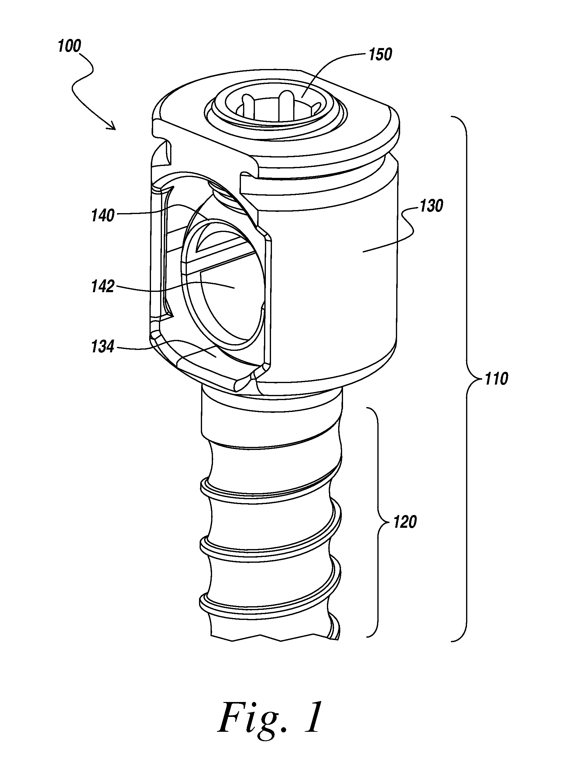
FIG. 1 illustrates an implant assembly according to an illustrative embodiment of the invention;
FIG. 2 illustrates an assembled implant assembly including a spinal rod movably received therein according to an illustrative embodiment of the invention;
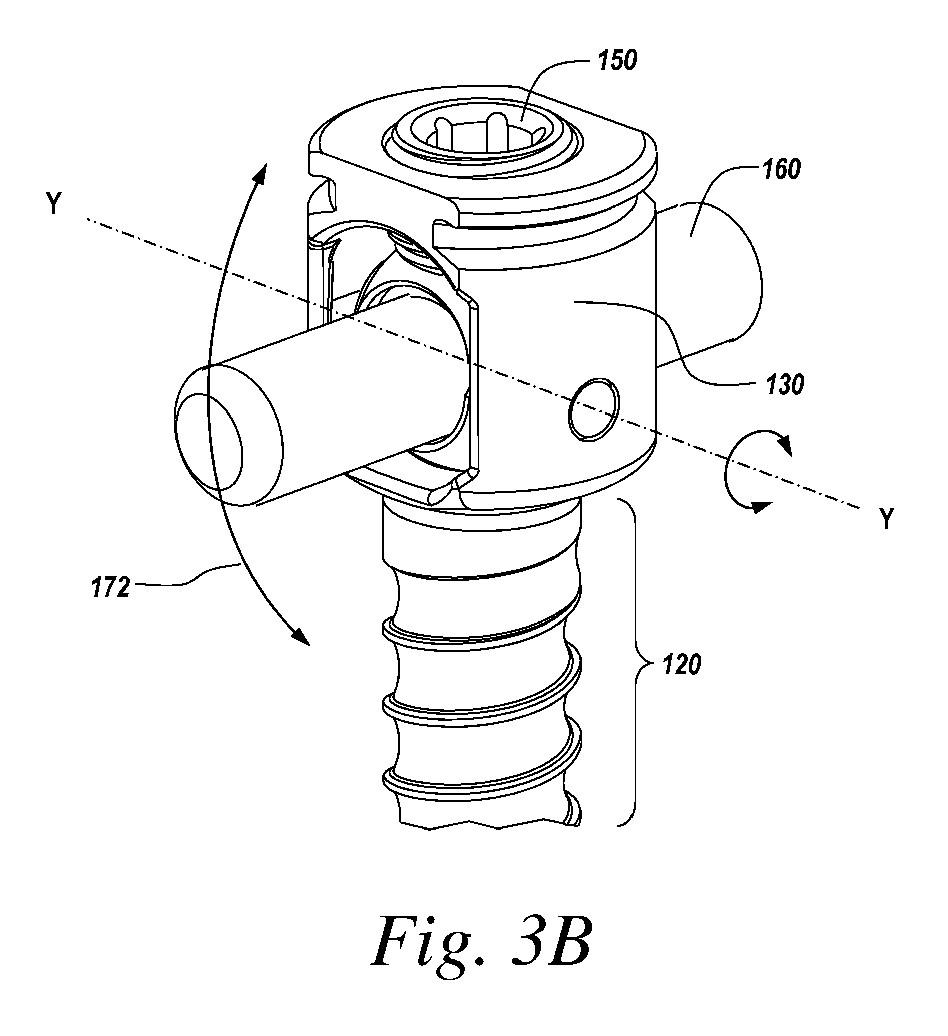
FIGS. 3A and 3B illustrate possible ranges of motion of the spinal rod relative to the bone screw body according to different embodiments of the invention;
FIG. 4 is an exploded view of an implant assembly according to one embodiment of the invention;
FIGS. 5A and 5B illustrate an alternate cradle configuration according to another embodiment of the invention;
FIG. 6 illustrates an alternate proximal head configuration according to another embodiment of the invention; and
FIG. 7 illustrates an embodiment of a method for connecting a spinal fixation element to one or more vertebral or pelvic bodies using the implant assembly.
DETAILED DESCRIPTION OF THE INVENTION
An implant assembly includes a screw body, including anchor portion and proximal head portion, and a cradle movably mounted in the screw body to allow for controlled angulation between a spinal connection element disposed in the cradle and the screw body. The cradle is pivotable in one or more selected directions about one or more axes relative to the screw body. The cradle may be generally, substantially spherical in shape and allow for unrestricted movement in one or more directions around one or more axis.
During spinal deformity surgeries, it may be necessary to de-rotate the vertebral or pelvic bodies to normalize the spine. Due to varying patient anatomy, insertion of fixed angle screws, where the anchor portion of the screw extends at a fixed angle relative to the rod-receiving portion of the screw can be difficult. Polyaxial and multi-axial screws, which allow the screw shank to pivot in all directions about the head portion, can be difficult to control and often result in undesirable movement in certain planes. An adjustable implant assembly allows for angulation of a spinal fixation element relative to the body of the screw that receives the spinal rod or other implant therein. For example, the implant assembly described herein allows for angulation of a spinal fixation element relative to the body of the screw. In certain embodiments, an adjustable implant assembly may be uniaxial and permit movement about a single selected axis.
The adjustable implant assembly disclosed may allow a surgeon to rotate vertebral or pelvic bodies and facilitates placement of the spinal fixation element. The adjustable implant assembly allows for a surgeon to achieve an ideal orientation of the spinal fixation element relative to the bone screw, without requiring the spinal fixation element to have a predetermined, fixed orientation, or necessarily be perpendicular to the longitudinal axis of the screw shank.
The exemplary adjustable implant assemblies of the illustrative embodiments may be employed to engage one or more spinal fixation elements to bone. For example, an implant assembly may be employed to fix a spinal plate, rod, and/or cable to a vertebra of the spine. Although the exemplary implant assemblies described below are designed primarily for use in spinal applications, one skilled in the art will appreciate that the structure, features and principles of the exemplary implant assemblies, as well as the other exemplary embodiments described below, may be employed to couple any type of orthopedic implant to any type of bone or tissue.
The illustrative adjustable implant assembly may be used to attach a non-rigid member to bone. For example, the adjustable implant assembly may be used to attach a rod, ligament, bar, cable or other non-rigid member extending between and connecting two bone screws, for example for connecting superior and inferior vertebra. Alternatively, the implant assembly may be used to attach a rigid member to bone. While the invention will be described with respect to an implant assembly that receives a spinal rod that is movably relative to the implant assembly, the invention is not limited to spinal rods and may be used with any suitable spinal connection element to be coupled to bone.
According to one aspect of the invention, an implant assembly 100, an embodiment of which is shown in FIGS. 1, is provided to allow movement of a spinal rod relative to a bone screw body. The implant assembly 100 has a screw body 110, which includes a distal anchor portion 120 for anchoring the screw assembly to bone and a proximal head portion 130. A cradle 140 for receiving a spinal fixation element (not shown) is seated in the proximal head 130 and is configured to move relative to the proximal head 130. In certain embodiments, the implant assembly 100 further includes a locking mechanism 150 for securing the position of the cradle 140 and a spinal fixation element relative to the proximal head 130. Each of these elements will be described in more detail below.
FIG. 2 shows the bone anchor assembly 100 used in conjunction with a spinal fixation element 160, in this case a spinal rod. The orientation of the cradle 140 may be selectively adjusted to controllably adjust the orientation of the spinal rod 160 relative to the screw body 110 of the implant assembly 100. Preferably, the cradle 140 allows for pivoting of the spinal rod 160 about one or more axes in one or more directions relative to the screw body 110 of the screw assembly 100. For example, the cradle 140 may allow the spinal rod 160 to pivot about a first axis X-X and/or a second axis Y-Y relative to the proximal head portion 130.
The cradle may have a central bore 142 that extends along an axis R-R, which defines and corresponds to the longitudinal axis of the spinal rod 160. In a default position, the axis R-R is preferably perpendicular to the longitudinal axis S-S of the body 110, though one skilled in the art will recognize that the cradle may have any suitable default orientation.
In the illustrative embodiment, the axis X-X extends through the center of the cradle 140, perpendicular to the axis R-R and aligns with the longitudinal axis S-S when the cradle is in a default position, so that the spinal rod 160 sweeps through a first plane P1. The illustrative first plane P1 is substantially parallel to the coronal plane of the body when the implant assembly 100 is employed in a patient. However, one skilled in the art will recognize that the first axis X-X about which the spinal rod 160 can pivot may have any suitable orientation and is not limited to the illustrative orientation.
The spinal rod 160 may also or alternatively pivot in a second plane P2 about axis Y-Y. In the illustrative embodiment, the axis Y-Y extends substantially perpendicular to the axis X-X, the axis S-S, and the axis R-R of the spinal rod 160 when the cradle 140 is in a default position, though one skilled in the art will recognize that the second axis about which the spinal rod 160 can pivot may have any suitable orientation. The plane P2 corresponds to the sagittal plane in a body when the illustrative biaxial implant assembly is implanted in the body. However, one skilled in the art will recognize that the second axis Y-Y about which the spinal rod 160 can pivot may have any suitable orientation and is not limited to the illustrative orientation.
The spinal rod 160 may be rotated by a selected amount about only the X-X axis, only the Y-Y axis, or both axis. The rotation about one axis may cause the orientation of the other axis to shift, or the orientation of each axis X-X and Y-Y may be fixed independently of the orientation of the other axis.
FIGS. 3A and 3B illustrate possible varieties of movement of the spinal rod 160 relative to the bone screw body according to different embodiments of the invention. The implant assembly may be poly-axial as shown in FIG. 3A. The spinal rod 160 of FIG. 3A may pivot through a cone of motion 170 defining the possible orientations of the spinal rod 160 relative to the body 110 through rotation about the X-X and/or Y-Y axis. Alternatively, the implant assembly may be monoaxial as shown in FIG. 3B. The spinal rod 160 of FIG. 3B may be confined to path 172 about the Y-Y axis.
In addition, for cylindrical rods or other spinal connection elements, the rod 160 may be rotated about axis R-R and/or slide within the cradle 140, providing an additional degree of freedom for attaining a selected orientation of the spinal rod relative to the screw body 110.
FIG. 4 is an exploded view of the exemplary implant assembly 100, illustrating the individual components of the assembly 100 that facilitate the adjustability according to an illustrative embodiment of the invention.
The anchor portion 120 of the screw assembly can have any suitable size, configuration and shape. The bone anchor 120 comprises a distal shaft 122 configured to engage bone. The distal shaft 122 of the bone anchor 120 extends along the longitudinal axis S-S. The distal shaft 122 may include one or more bone engagement mechanisms to facilitate gripping engagement of the bone anchor to bone. In the illustrated embodiment, the distal shaft 122 includes an external thread 124 extending along at least a portion of the shaft for engaging bone. In the illustrated embodiment, the external thread 124 is a single lead thread that extends from a distal tip 126 of the shaft to the proximal head portion 130, though one skilled in the art will recognize that the external thread may extend along any selected portion of the shaft and have any suitable number of leads. Other suitable bone engagement mechanisms include, but are not limited to, one or more annular ridges, multiple threads, dual lead threads, variable pitched threads, hole, slots, fenestrations, and/or any conventional bone engagement mechanism.
The proximal head portion 130 is sized and configured to receive a spinal fixation element 160 as well as the cradle 140. In this embodiment, the proximal head portion 130 is a closed-type screw head. The illustrative head portion 130 defines a central bore 132 for receiving the cradle 140 and the spinal rod 160. The central bore may be further shaped and dimensioned to allow the cradle 140 to move freely relative to the proximal head 130 when the cradle 140 is within the central bore 132. For example, the illustrative cradle is generally substantially spherical in shape. As such, the central bore may have a concave portion for receiving a generally substantially spherical shape. In certain embodiments, the ends 134 of the central bore 132 may be chamfered or rounded to allow for greater freedom of movement of a spinal fixation device 160 inserted in the proximal head portion 130.
As shown, the proximal head portion 130 may be rigidly coupled to or integral with the anchor portion 120 to form the screw body 110, though one skilled in the art will recognize that the proximal head portion 130 may alternatively be movably coupled to the anchor portion 120 to provide additional adjustability.
The longitudinal axis S-S of the bone anchor portion 120 preferably aligns with a longitudinal axis extending through the proximal head portion 130. However, one skilled in the art will recognize that the proximal head portion 130 may alternatively be offset from or extend at a selected angle relative to the anchor portion 120.
The cradle 140 allows for pivoting of the spinal fixation element 160 about a first axis X-X and/or a second axis Y-Y. In this example, the cradle 140 comprises a generally substantially spherical body with a central bore 142 for receiving the spinal fixation element 160. In certain embodiments, the cradle may include a lower element 144 and an upper element 146 that are combined to form the generally substantially spherical body of the cradle 140.
In this embodiment, the lower element 144 is half sphere shape and forms half of the generally substantially spherical boy of the cradle 140. The lower element 144 further defines a lower portion of the central bore 142. In this embodiment, the upper element 146 is half sphere in shape and forms the other corresponding half of the generally substantially spherical boy of the cradle 140. The upper element 146 also defines the upper portion of the central bore 142. When the upper element 146 is mated with the lower element 144, they form the generally substantially spherical body with a central bore 142. The spinal fixation element 160 is received in the central bore 142 between the lower and upper elements 144, 146. The central bore 142 is sized and dimensioned to capture the spinal fixation element 160 when the lower and upper elements 144, 146 are fully mated. In certain embodiments, the upper and lower elements 144, 146 of the cradle 140 may further include interlocking surface configuration 148 to assist in the mating of the lower and upper elements 144, 146. One skilled in the art will understand that other shapes, geometries, and configurations are possible.
While the generally substantially spherical shape of the cradle 140 allows for poly-axial movement, in certain embodiments, mono-axial movement may be desired. As such, cradle 140 may be provided with pivot points to restrict the movement of the cradle 140 to a first axis. An example of this can be seen in FIG. 4. Here the pivot pins 180 are provided to mate the cradle 140 and proximal head portion 130 and provide a pivot point along a first axis, such as the Y-Y axis. In this embodiment, the proximal head 130 is provided with thru-holes 136 and the cradle 140 has recesses 149 for receiving the pivot pins 180. When inserted, the pivot pins 180 pass through the thru-holes 136 of the proximal head portion 130 and engage the recesses 149 of the cradle 140. The pivot pins 180 provide a pivot point that allows movement in one around one axis, such as axis Y-Y.
While, the pivot points in this embodiment were provided by separate pivot pins 180 is should be understood that other pivot configuration are possible. For example, the pivot points may be formed by interlocking surface configurations one the cradle 140 and central bore 132 of the proximal head portion 130. In other embodiments, the generally substantially spherical body may include flat portions on opposite sides of the body to restrict movement of the cradle in the proximal head portion to a first axis.
In use, the spinal fixation element 160, such as a rod, is received in the central bore 142 of the cradle 140. The cradle 140, in turn resides in the central bore 132 of the proximal head portion 130. The proximal head portion is attached to the bone anchor 120 of the screw body 110 which is embedded in a bone. Thus, the bone anchor assembly 100 may be used to connect a spinal fixation element 160 to a vertebral or pelvic body. The cradle 140 allows the received spinal fixation element 160 to pivot about one or more selected axes in a selected direction relative to the bone anchor by a selected degree, preferably between 0.degree. and 90.degree.. Once the spinal fixation element 160 is in a desired orientation, a user may lock the orientation of the spinal fixation element 160 relative to the screw body 110 by inserting a locking mechanism, such as the set screw 150.
The locking mechanism secures the cradle 140 and, in turn, the spinal fixation element 160 within the central bore 132 of the proximal head portion and locks the cradle 140 and spinal fixation element 160 in the selected orientation within and relative to the screw body. In the illustrative embodiment, advancement of the locking mechanism into engagement with the upper portion 146 of the cradle 140. The upper element 146 of the cradle 140 engages the spinal fixation element 160 in the central bore 142. The spinal fixation engages the lower element 144 of the cradle 140. The lower element 144 engages a sidewall of the central bore 132 of the proximal head portion 132. Thus, the forces exerted by the side wall of the central bore and the locking mechanism 150 serve to mate the lower and upper elements 144, 146 of the cradle 140 capturing the spinal fixation element 160. The same forces also serve to secure the position of the cradle in the central bore 132.
The locking mechanism 150 may have any suitable size, shape, configuration for securing the spinal fixation element 160 and cradle 140 in a selected orientation relative to the screw body 110. The locking mechanism 150 may be secured to the screw body 110 through any suitable means, such as threads 152 on the locking mechanism 150. The threads 152 engage corresponding threads 154 on the proximal head portion 130. One skilled in the art will recognize that any suitable means for locking the spinal rod in a selected position and orientation relative to the screw body 110 may be used.
FIGS. 5A and 5B depict an example of a cradle configuration in which flat portions 147 are provided on opposite sided of the generally substantially spherical body of the cradle 140. FIG. 5A depicts a side view representation of the cradle 140 wherein one of the flat portions 147 is view head on. FIG. 5B depicts the cradle 140 rotated 90.degree. and the flat portions 147 are on either side central bore 142. When the cradle is in the proximal head portion 130 the flat surfaces 147 restrict the movement of the cradle to around one axis, such as axis Y-Y. The flat surfaces 147 serve to bind the cradle 140 against the central bore 132 of the proximal head restricting movement along around a second axis, such as X-X. Other geometries, shapes, and configurations will be apparent to one skilled in the art.
FIG. 6 depicts another embodiment of an implant assembly 100' having a different proximal head portion configuration. In this example, the proximal head 130' is an open type screw head. As with the previous embodiment, the implant assembly includes a bone anchor 120, proximal head 130' cradle 140 and locking mechanism 150. However, instead of a central bore, the proximal head portion 130' includes a U-shaped slot 132' and a cavity for receiving the cradle 140. The bone anchor 120, cradle 140, and locking mechanism 150 operate as described above.
FIG. 7 depicts one illustrative embodiment of method 700 of using the implant assembly 100 to attach a spinal fixation element 160 to one or more vertebral or pelvic bodies. A first implant assembly 100 is inserted into a vertebra or pelvic bone of the patient (step 710). A first portion of a spinal fixation element 160, such as a rod, is inserted into the cradle 140 of the first implant assembly 100 (step 720). The orientation of spinal fixation element 160 in relation to the screw body 110 may then be adjusted as desired (step 730). Once the spinal fixation element 160 is in the desired orientation, the position of the cradle 140 and spinal fixation element 160 may be locked using a locking mechanism 150 (step 740).
In certain embodiments, the spinal fixation element 160 may be further connected to other implant assemblies 100 thereby linking the first vertebral or pelvic body to a second vertebral or pelvic body. Thus, a second implant assembly 100 is inserted into the second vertebral or pelvic body (step 750). A second portion of the spinal fixation element 160 may be inserted in cradle 140 of the second implant assembly 100 (step 760). The orientation of spinal fixation element 160 in relation to the second screw body 110 may then be adjusted as desired (step 770). Once the spinal fixation element 160 is in the desired orientation, the position of the cradle 140 and spinal fixation element 160 may be locked using a locking mechanism 150 (step 780). This process may then be performed again with additional implant assemblies.
The components of the biaxial implant assembly of the illustrative embodiments of the invention may be manufactured from any suitable biocompatible material, including, but not limited to, metals and metal alloys such as titanium and stainless steel, polymers and/or ceramics. The components may be manufactured from the same or different materials though manufacturing processes known in the art.
The present invention has been described relative to an illustrative embodiment. Since certain changes may be made in the above constructions without departing from the scope of the invention, it is intended that all matter contained in the above description or shown in the accompanying drawings be interpreted as illustrative and not in a limiting sense.
It is also to be understood that the following claims are to cover all generic and specific features of the invention described herein, and all statements of the scope of the invention which, as a matter of language, might be said to fall therebetween.
* * * * *
D00000
D00001
D00002
D00003
D00004
D00005
D00006
D00007
XML
uspto.report is an independent third-party trademark research tool that is not affiliated, endorsed, or sponsored by the United States Patent and Trademark Office (USPTO) or any other governmental organization. The information provided by uspto.report is based on publicly available data at the time of writing and is intended for informational purposes only.
While we strive to provide accurate and up-to-date information, we do not guarantee the accuracy, completeness, reliability, or suitability of the information displayed on this site. The use of this site is at your own risk. Any reliance you place on such information is therefore strictly at your own risk.
All official trademark data, including owner information, should be verified by visiting the official USPTO website at www.uspto.gov. This site is not intended to replace professional legal advice and should not be used as a substitute for consulting with a legal professional who is knowledgeable about trademark law.