Barbed suture having increased holding strength
Nawrocki , et al. April 13, 2
U.S. patent number 10,973,513 [Application Number 13/248,542] was granted by the patent office on 2021-04-13 for barbed suture having increased holding strength. This patent grant is currently assigned to ETHICON, LLC. The grantee listed for this patent is Dennis L. Furman, David C. Lindh, Sr., Jesse G. Nawrocki, Jason T. Perkins. Invention is credited to Dennis L. Furman, David C. Lindh, Sr., Jesse G. Nawrocki, Jason T. Perkins.
| United States Patent | 10,973,513 |
| Nawrocki , et al. | April 13, 2021 |
Barbed suture having increased holding strength
Abstract
A wound closure device having a filamentary element having a proximal end and a distal end, and a stop element coupled thereto and having a leading edge area defined by thickness and a width and having a total surface area. The leading edge area is substantially perpendicular to a longitudinal axis of the filamentary element. The device may have a ratio of the leading edge area to the total surface area that is less than 10%, a ratio of the length to the maximum thickness of the stop element that is at least 4, or a ratio of the length to the width of the stop element is at least 1 for any given thickness.
| Inventors: | Nawrocki; Jesse G. (Annandale, NJ), Lindh, Sr.; David C. (Flemington, NJ), Perkins; Jason T. (Easton, PA), Furman; Dennis L. (East Windsor, NJ) | ||||||||||
|---|---|---|---|---|---|---|---|---|---|---|---|
| Applicant: |
|
||||||||||
| Assignee: | ETHICON, LLC (San Lorenzo,
PR) |
||||||||||
| Family ID: | 1000005482564 | ||||||||||
| Appl. No.: | 13/248,542 | ||||||||||
| Filed: | September 29, 2011 |
Prior Publication Data
| Document Identifier | Publication Date | |
|---|---|---|
| US 20130085525 A1 | Apr 4, 2013 | |
| Current U.S. Class: | 1/1 |
| Current CPC Class: | A61B 17/0401 (20130101); A61B 17/06166 (20130101); A61B 2017/0417 (20130101); A61B 2017/00004 (20130101); A61B 2017/06176 (20130101); A61B 2017/0464 (20130101) |
| Current International Class: | A61B 17/04 (20060101); A61B 17/06 (20060101); A61B 17/00 (20060101) |
| Field of Search: | ;606/228,224,222,223,144,232,300 |
References Cited [Referenced By]
U.S. Patent Documents
| 5053047 | October 1991 | Yoon |
| 5123913 | June 1992 | Wilk et al. |
| 5222976 | June 1993 | Yoon |
| 5312436 | May 1994 | Coffey |
| 5403346 | April 1995 | Loeser |
| 5450860 | September 1995 | O'Connor |
| 5683417 | November 1997 | Cooper |
| 5697950 | December 1997 | Fucci et al. |
| 5707394 | January 1998 | Miller et al. |
| 6033430 | March 2000 | Bonutti |
| 6050998 | April 2000 | Fletcher |
| 6117139 | September 2000 | Shino |
| RE36974 | November 2000 | Bonutti |
| 6241747 | June 2001 | Ruff |
| 6264675 | July 2001 | Brotz |
| 6319263 | November 2001 | Levinson |
| 6730112 | May 2004 | Levinson |
| 7468068 | December 2008 | Kolster |
| 7731732 | June 2010 | Ken |
| 7850700 | December 2010 | Sakura |
| 7850894 | December 2010 | Lindh, Sr. et al. |
| 8142513 | March 2012 | Shalon et al. |
| 8267961 | September 2012 | Popadiuk et al. |
| 8715320 | May 2014 | Lindh, Sr. |
| 8721681 | May 2014 | Ruff et al. |
| 2001/0044639 | November 2001 | Levinson |
| 2003/0149447 | August 2003 | Morency et al. |
| 2004/0122456 | June 2004 | Saadat et al. |
| 2005/0004576 | January 2005 | Benderev |
| 2005/0049635 | March 2005 | Leiboff |
| 2007/0257395 | November 2007 | Lindh et al. |
| 2008/0200751 | August 2008 | Browning |
| 2008/0281357 | November 2008 | Sung et al. |
| 2008/0312688 | December 2008 | Nawrocki et al. |
| 2009/0018577 | January 2009 | Leung et al. |
| 2009/0076547 | March 2009 | Sugimoto et al. |
| 2009/0248067 | October 2009 | Maiorino |
| 2009/0248070 | October 2009 | Kosa et al. |
| 2009/0312791 | December 2009 | Lindh, Sr. et al. |
| 2010/0084780 | April 2010 | Lindh, Sr. et al. |
| 2010/0146770 | June 2010 | Morency et al. |
| 2010/0211098 | August 2010 | Hadba et al. |
| 2010/0274283 | October 2010 | Kirsch |
| 2010/0298871 | November 2010 | Ruff et al. |
| 2011/0054522 | March 2011 | Lindh, Sr. et al. |
| 2011/0093010 | April 2011 | Genova et al. |
| 2011/0106152 | May 2011 | Kozlowski |
| 2012/0016183 | January 2012 | Gellman |
| 2012/0046525 | February 2012 | Russell et al. |
| 2013/0085525 | April 2013 | Nawrocki et al. |
| 1830200 | May 2010 | CN | |||
| 1867288 | Dec 2007 | EP | |||
| 1857236 | Nov 2009 | EP | |||
| 1858243 | Nov 2009 | EP | |||
| 1091282 | Nov 1967 | GB | |||
| 2010-184109 | Aug 2010 | JP | |||
| 2400162 | Sep 2010 | RU | |||
| 9506447 | Mar 1995 | WO | |||
| 2004030704 | Apr 2004 | WO | |||
| WO 2009/020795 | Feb 2009 | WO | |||
| WO 2010/051506 | May 2010 | WO | |||
| 2013048947 | Apr 2013 | WO | |||
| WO 2013/048947 | Apr 2013 | WO | |||
| 2019060365 | Mar 2019 | WO | |||
Other References
|
International Search Report for International Application No. PCT/US2012/056858 dated Nov. 29, 2012. cited by applicant. |
Primary Examiner: Yabut; Diane D
Claims
What is claimed is:
1. A surgical suture adapted to approximate opposing tissue surfaces without knot tying, the surgical suture having a first end and a second end comprising: a filamentary element having a proximal end and a distal end, a plurality of barbs extending outwardly therefrom so as to allow movement of the surgical suture through tissue in a first direction toward the proximal end of the filamentary element and first end of the surgical suture and resist movement in a second opposite direction; a stop element having a total surface area and a substantially planar leading edge area defined by thickness and a width, wherein the stop element is coupled to the distal end of the filamentary element so that the leading edge area is substantially perpendicular to a longitudinal axis of the filamentary element and faces the first end of the surgical suture and lies substantially within a first plane, the stop element also having a length extending in the direction of the longitudinal axis of the filamentary element that is greater than the width, the stop element adapted to resist movement of the surgical suture in said first direction; wherein a ratio of the leading edge area to the total surface area is less than 10%, and wherein the filamentary element and stop element are comprised of the same polymeric material.
2. The surgical suture according to claim 1, wherein the ratio of the leading edge area to the total surface area is less than 5%.
3. The surgical suture according to claim 1, wherein the width of the stop element is greater than 70 mils.
4. The surgical suture according to claim 3, wherein a length of the stop element is greater than 70 mils.
5. The surgical suture according to claim 1, wherein a maximum thickness of said stop element is between 6 and 25 mils.
6. The surgical suture according to claim 1, wherein the thickness of the stop element varies.
7. The surgical suture according to claim 6, wherein a minimum thickness of the stop element is between 4 and 12 mils.
8. The surgical suture according to claim 6, wherein the leading edge thickness includes a maximum thickness at a center and/or at first and/or second outer edges, and a minimum thickness at a location between the center and the first outer edge and between the center and the second outer edge.
9. The surgical suture according to claim 1, further comprising a plurality of projections extending outwardly from the filamentary element along at least a portion of its length.
10. The surgical suture according to claim 9, wherein said plurality of projections extending outwardly from said filamentary element by approximately 6-25 mils.
11. The surgical suture according to claim 1, wherein the polymeric is absorbable or non-absorbable.
12. The surgical suture according to claim 11, wherein the polymeric material selected from the group consisting of absorbable and non-absorbable homopolymers, random copolymers, block copolymers or blends made from polydioxanone, polyglactin, polyglycolic acid, copolymers of glycolide, lactide, and/or caprolactone, polyoxaesters, poliglecaprone, polypropylene, polyethylene, polyvinylidene fluoride (PVDF), hexafluoropropylene, copolymers of vinylidene fluoride and hexafluoropropylene, polyesters, polyethylene terephthalate, polybutylene terephthalate, glycol-modified polyethylene terephthalate, polytetrafluoroethylene, fluoropolymers, thermoplastic elastomers, ionomers, copolymers of ethylene and methacrylic acid, polyamides, polytetramethylene oxide, polystyrene, polybutadiene, polybutylene, etc. including combinations and/or copolymers of absorbable and non-absorbable materials.
13. The surgical suture according to claim 1, wherein a ratio of a length to maximum thickness of the stop element is greater than 4.
14. The surgical suture according to claim 1, wherein a maximum thickness of the stop is approximately 8-25 mils, the width of the stop element is approximately 70-120 mils, and a length of the stop element is approximately 39-200 mils.
15. A surgical suture adapted to approximate opposing tissue surfaces without knot tying comprising: a filamentary element extending along a longitudinal axis between a proximal end and a distal end, and having a plurality of barbs extending outwardly therefrom so as to allow movement of the surgical suture through tissue in a first direction toward the proximal end of the filamentary element and resist movement in a second opposite direction; a stop element having a length extending substantially parallel to the longitudinal axis of the filamentary element, and having a substantially planar leading edge area extending substantially perpendicular to said longitudinal axis and defined by a width and a maximum thickness, the leading edge area being fixedly coupled to the distal end of the filamentary element along said leading edge area; wherein the ratio of the length to the maximum thickness of the stop element is at least 4.
16. The surgical suture according to claim 15, wherein the maximum thickness of the stop element is between 8 and 25 mils.
17. The surgical suture according to claim 16, wherein the length of the stop element is greater than 39 mils.
18. The surgical suture according to claim 17, wherein the width of the stop element is between 70 and 120 mils.
19. The surgical suture according to claim 17, further comprising a plurality of projections extending outwardly from the filamentary element along at least a portion of its length.
20. The surgical suture according to claim 17, wherein a thickness of the stop element varies.
21. The surgical suture according to claim 20, wherein a leading edge of the stop element includes a maximum thickness at a center and/or at first and/or second outer edges, and a minimum thickness at a location between the center and the first outer edge and between the center and the second outer edge.
Description
FIELD OF THE INVENTION
The present invention relates generally to the field of medical devices, and more particularly to barbed suture devices having increased holding strength.
BACKGROUND
Many wound and surgical incisions are closed using surgical sutures or some other surgical closure device. Barbed sutures are well known and have recently been gaining attention for various medical applications. Typically, barbed sutures are constructed with a series of "barbs" or "protrusions" (used interchangeably herein) that extend outwardly from the suture, and function to increase the holding strength of the suture and/or eliminate the need for knot tying. The size and shape of the barbs have practical limitations in a surgical setting, and cannot simply be increased wherever increased holding strength is desired.
Some sutures and barbed sutures have been known to include anchors, tabs or the like on the distal end of the suture to provide a "stop" at the end that increases the holding strength of the suture and eliminates the need to tie knots to secure the suture. Conventional thinking dictates that the larger the surface area of the stop in a direction perpendicular to the direction of insertion of the suture, the more holding strength that will be achieved. Again, there are practical limitations on size however, as large masses may be intolerable in surgical procedures and/or palpable and therefore undesirable. Further, with T-shaped stops, the perpendicular portion is structurally weak when a bending moment is applied as it would be when pulling on the suture to approximate a wound.
Therefore, there remains a need to enhance the holding strength of a surgical suture without significantly increasing the insertion force, stiffness of the suture, or palpability of the device.
SUMMARY OF THE INVENTION
The present invention provides a wound closure device including a filamentary element having a proximal end and a distal end, a stop element coupled to the distal end of the filamentary element and having a leading edge area defined by thickness and a width, and a total surface area. The leading edge area faces substantially perpendicular to a longitudinal axis of the filamentary element, and the ratio of the leading edge area to the total surface area is less than 10%. According to one embodiment, the ratio is less than 5%.
According to various embodiments, the width of the stop element may be greater than 70 mils, the length of the stop element may be greater than 70 mils, and/or the maximum thickness of said stop element may be between 6 and 25 mils.
According to one embodiment, the thickness of the stop element varies, and/or a minimum thickness of the stop element may be between 4 and 12 mils. According to yet another embodiment, the leading edge thickness includes a maximum thickness at a center and/or at first and/or second outer edges, and a minimum thickness at a location between the center and the first outer edge and between the center and the second outer edge.
In yet another embodiment, the wound closure device further includes a plurality of projections extending outwardly from the filamentary element along at least a portion of its length. The plurality of projections may extend outwardly from said filamentary element by approximately 6-25 mils.
The device may be made of a polymeric, metallic or ceramic material that are absorbable or non-absorbable. In yet another embodiment, the device is made of a polymer material selected from the group consisting of absorbable and non-absorbable homopolymers, random copolymers, block copolymers or blends made from polydioxanone, polyglactin, polyglycolic acid, copolymers of glycolide, lactide, and/or caprolactone, polyoxaesters, poliglecaprone, polypropylene, polyethylene, polyvinylidene fluoride (PVDF), hexafluoropropylene, copolymers of vinylidene fluoride and hexafluoropropylene, polyesters, polyethylene terephthalate, polybutylene terephthalate, glycol-modified polyethylene terephthalate, polytetrafluoroethylene, fluoropolymers, thermoplastic elastomers, ionomers, copolymers of ethylene and methacrylic acid, polyamides, polytetramethylene oxide, polystyrene, polybutadiene, polybutylene, etc. including combinations and/or copolymers of absorbable and non-absorbable materials.
According to yet another embodiment, a ratio of the length to maximum thickness of the stop element is greater than 4.
In yet another embodiment, the maximum thickness of the stop is approximately 8-25 mils, the width of the stop is approximately 70-120 mils, and the length of the stop is approximately 39-200 mils.
The present invention also provides a wound closure device including a filamentary element extending along a longitudinal axis between a proximal end and a distal end, and a stop element coupled to the distal end of the filamentary element and that has a length extending substantially parallel to the longitudinal axis of the filamentary element, a width extending substantially perpendicular to said longitudinal axis, and a maximum thickness. The ratio of the length to the maximum thickness of the stop element is at least 4.
In alternate embodiments, the maximum thickness of the stop element is between 8 and 25 mils, the length of the stop element is greater than 39 mils, and/or the width of the stop element is between 70 and 120 mils.
In yet another embodiment, the wound closure device further includes a plurality of projections extending outwardly from the filamentary element along at least a portion of its length.
In yet another embodiment, the thickness of the stop element varies, and in another particular embodiment, the leading edge thickness includes a maximum thickness at a center and/or at first and/or second outer edges, and a minimum thickness at a location between the center and the first outer edge and between the center and the second outer edge.
Also provided is a wound closure device including a filamentary element extending along a longitudinal axis between a proximal end and a distal end, and a stop element coupled to the distal end of the filamentary element. The stop element has a length extending substantially parallel to the longitudinal axis of the filamentary element, a width extending substantially perpendicular to said longitudinal axis, and a maximum thickness, and for any given maximum thickness of the stop element, the ratio of the length to the width of the stop element is at least 1.
In a further embodiment, the ratio of the length to the width of the stop element is at least 1.5.
These and other objects, features and advantages of the present invention will be apparent from the following detailed description of illustrative embodiments thereof, which is to be read in connection with the accompanying drawings.
BRIEF DESCRIPTION OF THE DRAWINGS
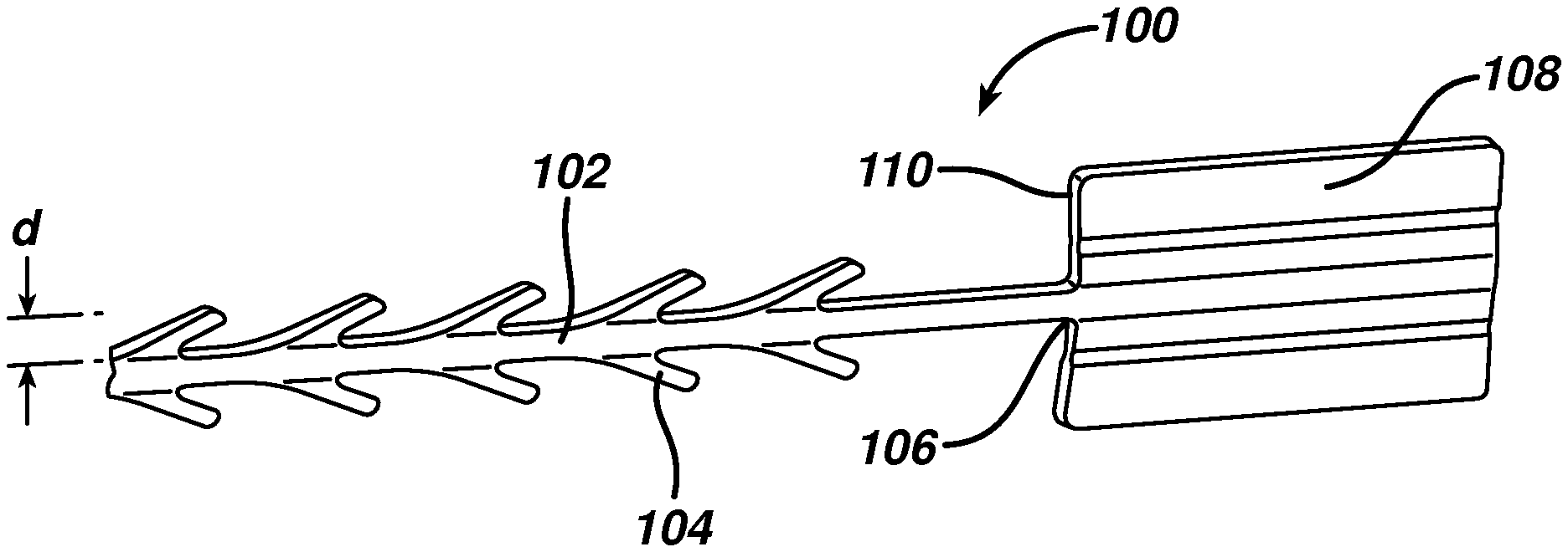
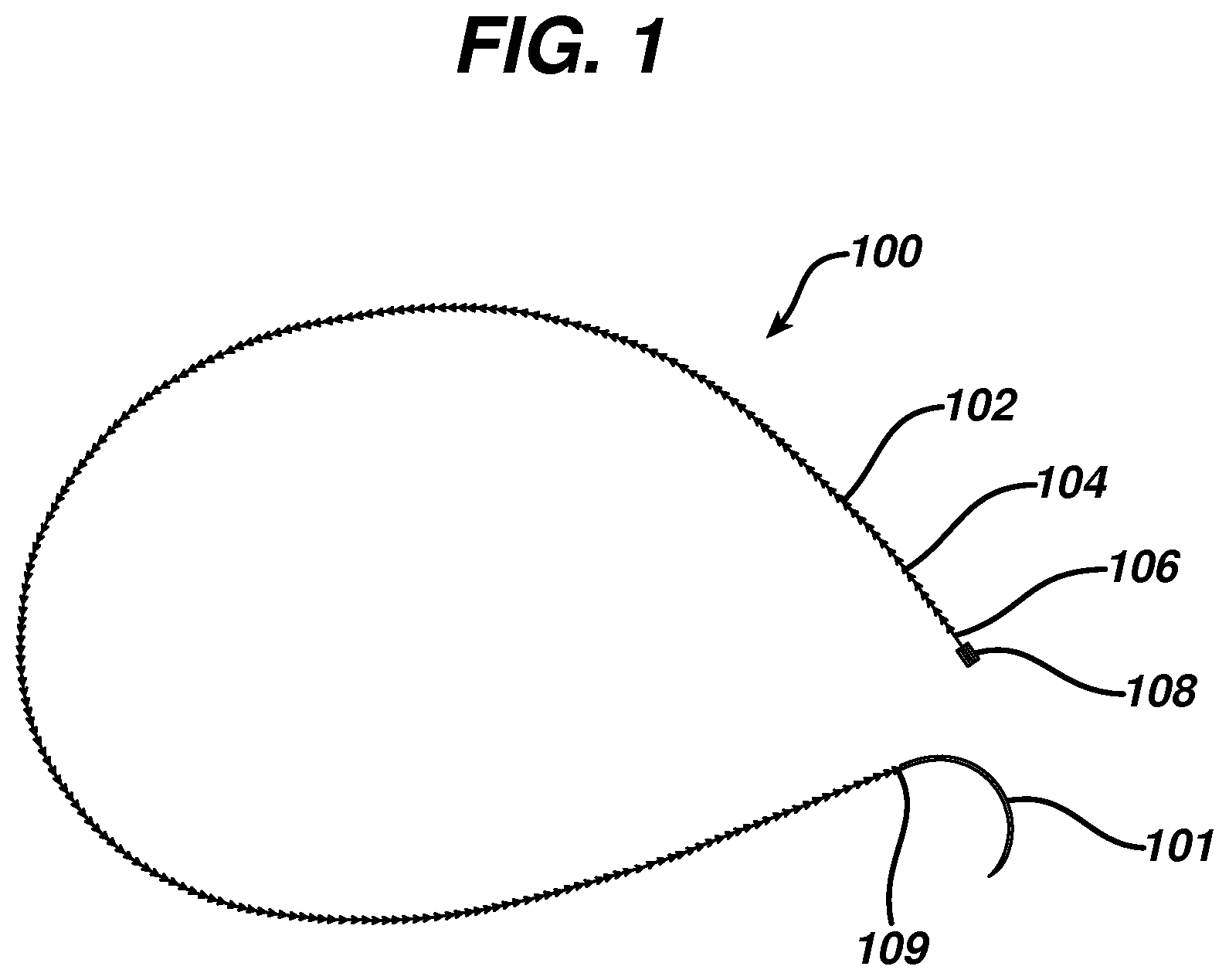
FIG. 1 illustrates a wound closure device according to the present invention including an insertion needle;
FIG. 2 is an enlarged view of the distal end of the wound closure device of FIG. 1;
FIG. 3 is a top view of the stop element of the wound closure device of FIG. 1;
FIG. 4 is a side view of the stop element of the wound closure device of FIG. 1;
FIG. 5 is a cross-sectional view of the leading edge of the stop element of the wound closure device of FIG. 1;
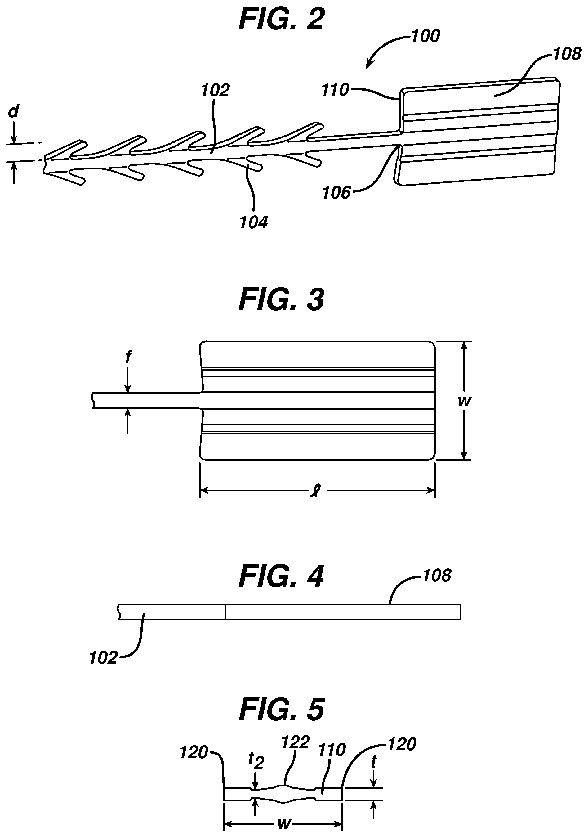
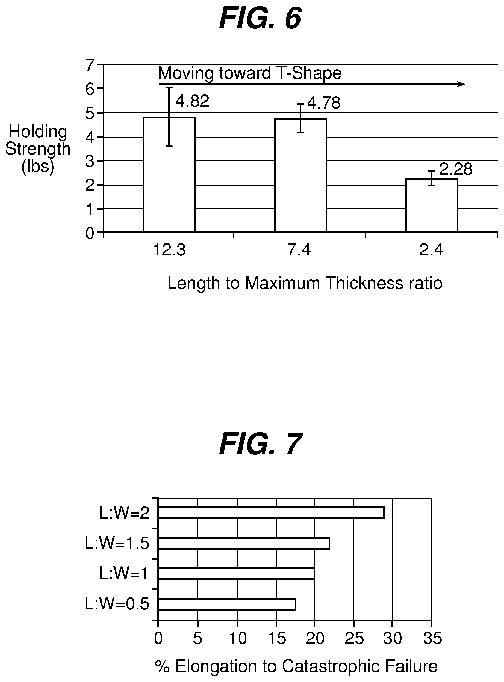
FIG. 6 is a graph illustrating the holding strength of fixation tabs of equal leading edge maximum thickness and width, but with varying length;
FIG. 7 is a graph illustrating elongation of a fixation tab as a function of length to width ratio for a given maximum thickness;
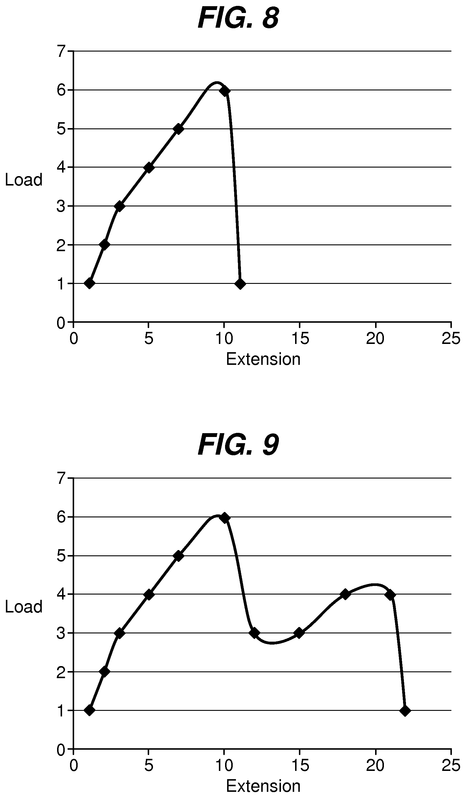
FIG. 8 is a graph illustrating a load-extension curve for a fixation tab length to width ratio of 0.5; and
FIG. 9 is a graph illustrating a load-extension curve for a fixation tab length to width ratio of 2.
DETAILED DESCRIPTION
FIG. 1 illustrates an exemplary embodiment of a wound closure device 100 according to the present invention. The wound closure device 100 includes a filamentary element 102 comprised of any suitable surgical suture material (i.e., absorbable and non-absorbable polymeric materials, metallic, or ceramic materials) that preferably includes a plurality of barbs 104 that extend outwardly therefrom. The suture may be formed by any suitable method, but preferably is compound profile punched from preformed material in a manner described in more detail in U.S. Patent Publication No. 2007/0257395, which is incorporated herein by reference in its entirety. The proximal end 109 of the wound closure device may include a needle or other insertion device 101. At the distal end 106 of the wound closure device is a fixation tab or stop element or the like 108. The stop 108 has a leading edge 110 defined by a leading edge thickness t and a leading edge width w, and also has a length l as shown in FIGS. 3-5. As indicated previously, known T-shaped configurations have relatively weak stiffness when a bending moment is applied, such as when tension is applied to the suture to approximate a wound. The graph depicted in FIG. 6 more clearly illustrates the advantage of the present invention over a T-shaped end configuration. Fixation tabs of equal leading edge maximum thickness (t) and width (w) (leading edge area), but varying length (l) were made and the holding strength tested. The holding strength was tested by passing the barbed suture through a porcine abdominal wall fascia sample and pulling against the fixation tab until failure occurred either by the stop breaking in some fashion, the stop pulling through the tissue, or a combination of both. The maximum load prior to failure was recorded and illustrated in FIG. 6.
As shown therein, the holding strength decreases as the geometry becomes more like a T-shaped member, or in other words, as the ratio of length to leading edge area or length to maximum thickness decreases. The holding strength can be increased by increasing the thickness or width of the stop, but as indicated previously, there are practical and clinical limitations on the size and mass that can be implanted.
In addition to the length to maximum thickness or leading edge area ratio, the length l to width w ratio is also a significant consideration for any given maximum thickness. Surprisingly and counter-intuitively, a ratio of at least 1:1 provides much increased holding strength. FIG. 7 illustrates the elongation of the fixation stop or tab as a function of the length to width ratio for a given maximum thickness. As shown, the percentage of elongation (or more simply the amount of deformation) required to reach catastrophic failure increases with increasing length to width ratio.
In addition to raw elongation percentages, the actual amount of energy required for the failure of the device increases with increasing length to width ratios. This is illustrated by FIGS. 8 and 9, in which the area under the load-extension curve is a measure of the strain energy until catastrophic failure. As the length to width ratio increases, the amount of strain energy required to reach catastrophic failure significantly increases. FIG. 8 illustrates a load-extension curve for a fixation tab having a length to width ratio of 0.5:1. As illustrated, the device reaches a peak load then decreases dramatically with sudden failure. FIG. 9 illustrates a load-extension curve for a fixation tab having a length to width ratio of 2:1. As illustrated, the curve has a second peak, and much greater extension before catastrophic failure occurs. In other words, the strain energy significantly increases as the length to width ratio increases from 0.5 to 2.
Referring once again to FIGS. 3-5, the leading edge area of the stop element has relatively little surface area in contact with tissue when the suture is under tension, but its ratio of length l to maximum thickness t is very large. Thus, the actual area in contact with tissue (leading edge area 110) in the direction of load is very small relative to the overall dimensions of the fixation stop or tab. This relatively long length, but minimal thickness allows the stop to be placed in the wound in a relatively flat position, which minimizes palpability and allows the opposing sides of the tissue to neatly cover the stop. Since the stop lies nicely in the tissue, it can be placed at the apex of the wound, lateral to one side of the wound etc, without impeding the surgeon's individual closure technique.
In a preferred embodiment, the leading edge relative to the total surface area of the stop (sum of surface area of all sides) is small, preferably less than 10% and more preferably less than 5%. This is counterintuitive, as conventional thinking dictates that in order to increase holding strength and/or minimize failure, one must increase or maximize the surface area under load in order to spread out the load and decrease the load per unit area. The relatively long length l, but minimal thickness t results in clinical advantages, including flat positioning that minimizes palpability, and versatile positioning as mentioned above.
According to a preferred embodiment shown in detail in the cross-sectional view of FIG. 5, the leading edge area of the stop of the present invention preferably is not rectangular, but rather has a thickness that varies across its width. The preferred stop 108 has a maximum thickness t at its outer edges 120 and center 122, and a minimum thickness t.sub.2 at points between the center and outer edges. In this embodiment, the filamentary element has a filament width f of approximately 5-25 mils, and the barbs 104 extend outwardly therefrom by a distance d of approximately 6-25 mils. The stop has a length l of at least 39 mils, preferably 100 to 200 mils, and a width of greater than 70 mils, more preferably greater than 90 mils, and most preferably greater than 95 mils. Further, the maximum thickness t is greater than 6 mils, and preferably between 10 and 25 mils, and the minimum thickness t.sub.2 is less than 15 mils, but preferably between approximately 5 and 9 mils. The length to maximum thickness ratio is preferably greater than 4, and the length to minimum thickness is preferably greater than 9. Finally, the length to width ratio is greater than 1, and preferably greater than 1.5.
Although illustrative embodiments of the present invention have been described herein with reference to the accompanying drawings, it is to be understood that the invention is not limited to those precise embodiments and that various other changes and modifications may be effected herein by one skilled in the art without departing from the scope or spirit of the invention.
* * * * *
D00000
D00001
D00002
D00003
D00004
XML
uspto.report is an independent third-party trademark research tool that is not affiliated, endorsed, or sponsored by the United States Patent and Trademark Office (USPTO) or any other governmental organization. The information provided by uspto.report is based on publicly available data at the time of writing and is intended for informational purposes only.
While we strive to provide accurate and up-to-date information, we do not guarantee the accuracy, completeness, reliability, or suitability of the information displayed on this site. The use of this site is at your own risk. Any reliance you place on such information is therefore strictly at your own risk.
All official trademark data, including owner information, should be verified by visiting the official USPTO website at www.uspto.gov. This site is not intended to replace professional legal advice and should not be used as a substitute for consulting with a legal professional who is knowledgeable about trademark law.