Secondary battery
Ji , et al. April 6, 2
U.S. patent number 10,971,781 [Application Number 16/338,227] was granted by the patent office on 2021-04-06 for secondary battery. This patent grant is currently assigned to LG Chem, Ltd.. The grantee listed for this patent is LG Chem, Ltd.. Invention is credited to Cheon Hee Bok, Sang Gu Ji, Da Na Kim, Sang Uck Kim, Yong Han Kim, Myung An Lee, Geun Young Park.
| United States Patent | 10,971,781 |
| Ji , et al. | April 6, 2021 |
Secondary battery
Abstract
A secondary battery is disclosed. According to the present invention, in a case in which the secondary battery is ignited, a gas and materials within the secondary battery may be smoothly discharged to improve safety when the secondary battery is ignited. In order to achieve the above-described object, according to an aspect of the present invention, a secondary battery includes: an electrode assembly; a battery can accommodating the electrode assembly; and a coating part applied to the battery can, wherein the battery can includes a slim part having a relatively thinner thickness than that of the other region of the battery can, and the coating part is applied to the slim part and made of a metal material having tensile strength less than that of the slim part.
| Inventors: | Ji; Sang Gu (Daejeon, KR), Bok; Cheon Hee (Daejeon, KR), Lee; Myung An (Daejeon, KR), Kim; Sang Uck (Daejeon, KR), Park; Geun Young (Daejeon, KR), Kim; Yong Han (Daejeon, KR), Kim; Da Na (Daejeon, KR) | ||||||||||
|---|---|---|---|---|---|---|---|---|---|---|---|
| Applicant: |
|
||||||||||
| Assignee: | LG Chem, Ltd. (N/A) |
||||||||||
| Family ID: | 1000005471529 | ||||||||||
| Appl. No.: | 16/338,227 | ||||||||||
| Filed: | April 13, 2018 | ||||||||||
| PCT Filed: | April 13, 2018 | ||||||||||
| PCT No.: | PCT/KR2018/004365 | ||||||||||
| 371(c)(1),(2),(4) Date: | March 29, 2019 | ||||||||||
| PCT Pub. No.: | WO2018/190690 | ||||||||||
| PCT Pub. Date: | October 18, 2018 |
Prior Publication Data
| Document Identifier | Publication Date | |
|---|---|---|
| US 20200035968 A1 | Jan 30, 2020 | |
Foreign Application Priority Data
| Apr 13, 2017 [KR] | 10-2017-0047937 | |||
| Current U.S. Class: | 1/1 |
| Current CPC Class: | H01M 50/116 (20210101); H01M 50/578 (20210101); H01M 50/107 (20210101); H01M 50/3425 (20210101); H01M 50/342 (20210101); H01M 2200/20 (20130101); H01M 50/30 (20210101) |
| Current International Class: | H01M 50/342 (20210101); H01M 50/107 (20210101); H01M 50/116 (20210101); H01M 50/578 (20210101); H01M 50/30 (20210101) |
References Cited [Referenced By]
U.S. Patent Documents
| 3855006 | December 1974 | Kegelman |
| 2003/0077505 | April 2003 | Goda et al. |
| 2010/0310927 | December 2010 | Imai |
| 2012/0196163 | August 2012 | Shimizu |
| 2012/0219834 | August 2012 | Park |
| 2013/0236752 | September 2013 | Yang et al. |
| 2014/0045000 | February 2014 | Kim |
| 2014/0072841 | March 2014 | Yamada et al. |
| 2015/0280191 | October 2015 | Matsudo et al. |
| 2016/0260552 | September 2016 | Sato et al. |
| 2696387 | Feb 2014 | EP | |||
| H07211300 | Aug 1995 | JP | |||
| H11213978 | Aug 1999 | JP | |||
| 2001143664 | May 2001 | JP | |||
| 2001307707 | Nov 2001 | JP | |||
| 2001345083 | Dec 2001 | JP | |||
| 2003346762 | Dec 2003 | JP | |||
| 3593709 | Nov 2004 | JP | |||
| 2012133904 | Jul 2012 | JP | |||
| 201436014 | Feb 2014 | JP | |||
| 2014103026 | Jun 2014 | JP | |||
| 2014232856 | Dec 2014 | JP | |||
| 2016167575 | Sep 2016 | JP | |||
| 20010008860 | Feb 2001 | KR | |||
| 20020080428 | Oct 2002 | KR | |||
| 20030084153 | Nov 2003 | KR | |||
| 20050018269 | Feb 2005 | KR | |||
| 20060027263 | Mar 2006 | KR | |||
| 20070067776 | Jun 2007 | KR | |||
| 20090060495 | Jun 2009 | KR | |||
| 20090105547 | Oct 2009 | KR | |||
| 20130063206 | Jun 2013 | KR | |||
| 101310735 | Sep 2013 | KR | |||
| 20130100713 | Sep 2013 | KR | |||
| 101696964 | Jan 2017 | KR | |||
| 20170004720 | Jan 2017 | KR | |||
| 2011145263 | Nov 2011 | WO | |||
| 2011158822 | Dec 2011 | WO | |||
| 2012153675 | Nov 2012 | WO | |||
| 2014073518 | May 2014 | WO | |||
Other References
|
Extended European Search Report including Written Opinion for Application No. EP18784168.9, dated Oct. 2, 2019, pp. 1-9. cited by applicant . International Search Report for PCT/KR2018/004365, dated Nov. 14, 2018. cited by applicant. |
Primary Examiner: Smith; Jeremiah R
Attorney, Agent or Firm: Lerner, David, Littenberg, Krumholz & Mentlik, LLP
Claims
The invention claimed is:
1. A secondary battery comprising: an electrode assembly; a battery can defining an outer wall accommodating the electrode assembly therein, the outer wall comprising a main body having a first thickness and a slim part having a second thickness thinner than the first thickness; and a coating part applied to the slim part and made of a metal material having a tensile strength less than a tensile strength of the slim part, wherein a ratio of the tensile strength of the coating part to the tensile strength of the slim part is 0.5 to 0.7.
2. The secondary battery of claim 1, wherein the battery can comprises a beading part provided in an upper portion of the battery can and having a shape that is recessed inward, and the slim part and the coating part are located below the beading part.
3. The secondary battery of claim 2, wherein the slim part and the coating part are each disposed between the beading part and a central portion of the battery can.
4. The secondary battery of claim 1, wherein the coating part has a third thickness, and a sum of the second thickness of the slim part and the third thickness of the coating part is the same as the first thickness of the main body of the outer wall of the battery can.
5. The secondary battery of claim 1, wherein the slim part has a shape having at least two surfaces, and the at least two surfaces extend in different directions and intersect each other.
6. The secondary battery of claim 5, wherein the at least two surfaces radially intersect each other.
7. The secondary battery of claim 5, wherein a crossing portion of the slim part in which the at least two surfaces intersect each other has a fourth thickness less than the second thickness of a remaining portion of the slim part.
8. The secondary battery of claim 1, wherein a ratio of the second thickness of the slim part to the first thickness of the main body of the outer wall of the battery can is 0.6 to 0.7.
9. The secondary battery of claim 1, wherein the second thickness of the slim part is 0.09 mm to 0.11 mm, and the first thickness of the main body of the outer wall of the battery can is 0.14 mm to 0.16 mm.
10. The secondary battery of claim 1, wherein the coating part is made of an aluminum material.
Description
CROSS-REFERENCE TO RELATED APPLICATION
The present application is a national phase entry under 35 U.S.C. .sctn. 371 of International Patent Application No. PCT/KR2018/004365, filed on Apr. 13, 2018, published in Korean, which claims priority from Korean Patent Application No. 10-2017-0047937, filed on Apr. 13, 2017, the disclosures of which are hereby incorporated herein by reference.
TECHNICAL FIELD
The present invention relates to a secondary battery, and more particularly, to a secondary battery having a structure that is capable of effectively discharging a gas within the secondary battery.
BACKGROUND ART
In case of secondary batteries capable of being repeatedly chargeable and dischargeable, it is important to secure safety. To secure safety of such a secondary battery, according to the related art, a can-type secondary battery is provided with a safety vent that is disposed in an upper portion of the secondary battery and ruptured when a pressure within the secondary battery increases to discharge a gas within the secondary battery to the outside.
The reason for the increase in pressure within the secondary battery may vary. In the case of ignition of the secondary battery, which is one of the causes, there is a great risk of safety accidents and the like in that the pressure within the secondary battery sharply increases. Particularly, in the case in which the secondary battery is ignited, a discharge path for the gas, which is formed while the safety vent is ruptured may be blocked by an electrode and a separator, which are combusted in the secondary battery. In this case, there is a great risk of the safety accidents such as explosion and the like because the gas and materials within the secondary battery are not properly discharged.
DISCLOSURE OF THE INVENTION
Technical Problem
Therefore, an object of the present invention is to improve safety of a secondary battery by allowing a gas and materials within the secondary battery to be smoothly discharged when the secondary battery is ignited.
Technical Solution
In order to achieve the above-described object, according to an aspect of the present invention, a secondary battery includes: an electrode assembly; a battery can defining an outer wall accommodating the electrode assembly therein, the outer wall including a main body having a first thickness and a slim part having a second thickness thinner than the first thickness; and a coating part applied to the slim part and made of a metal material having a tensile strength less than a tensile strength of the slim part.
The battery can may include a beading part provided in an upper portion of the battery can and having a shape that is recessed inward, and the slim part and the coating part may be located below the beading part.
The coating part may have a third thickness, and a sum of the second thickness of the slim part and the third thickness of the coating part may be the same as the first thickness of the main body of the outer wall of the battery can.
The slim part may have a shape having at least two surfaces, and the at least two surfaces may extend in different directions and intersect each other.
The at least two surfaces may radially intersect each other.
A crossing portion of the slim part in which the at least two surfaces interest each other may have a fourth thickness less than the second thickness of a remaining portion of the slim part.
A ratio of the second thickness of the slim part to the first thickness of the main body of the outer wall of the battery can may be 0.6 to 0.7.
The second thickness of the slim part may be 0.09 mm to 0.11 mm, and first thickness of the main body of the outer wall of the battery can may be 0.14 mm to 0.16 mm.
The slim part and the coating part may each be disposed between the beading part and a central portion of the battery can.
The coating part may be made of an aluminum material.
A ratio of the tensile strength of the coating part to the tensile strength of the slim part may be 0.5 to 0.7.
Advantageous Effects
According to the present invention, in the case in which the secondary battery is ignited, the gas and materials within the secondary battery may be smoothly discharged to improve the safety when the secondary battery is ignited.
BRIEF DESCRIPTION OF THE DRAWINGS
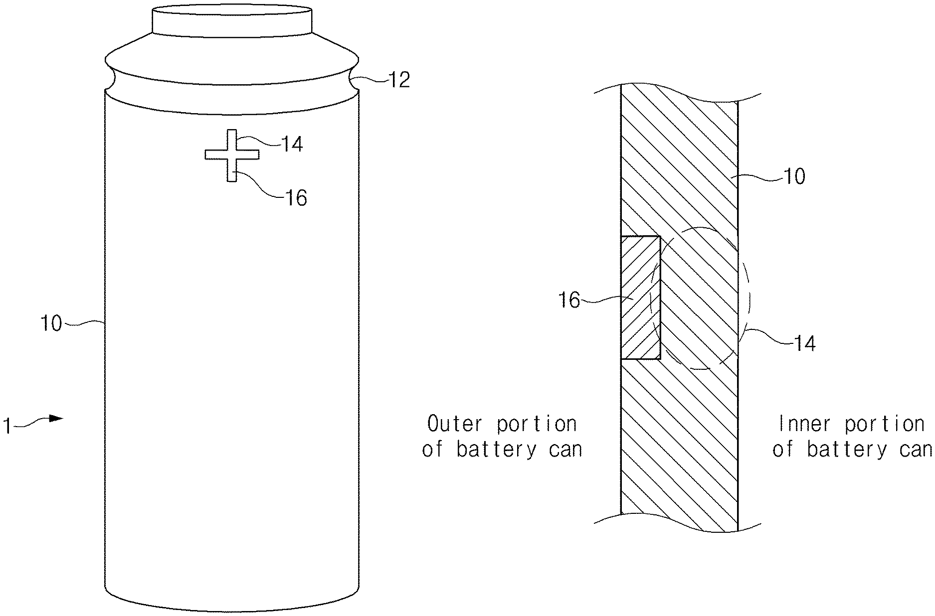
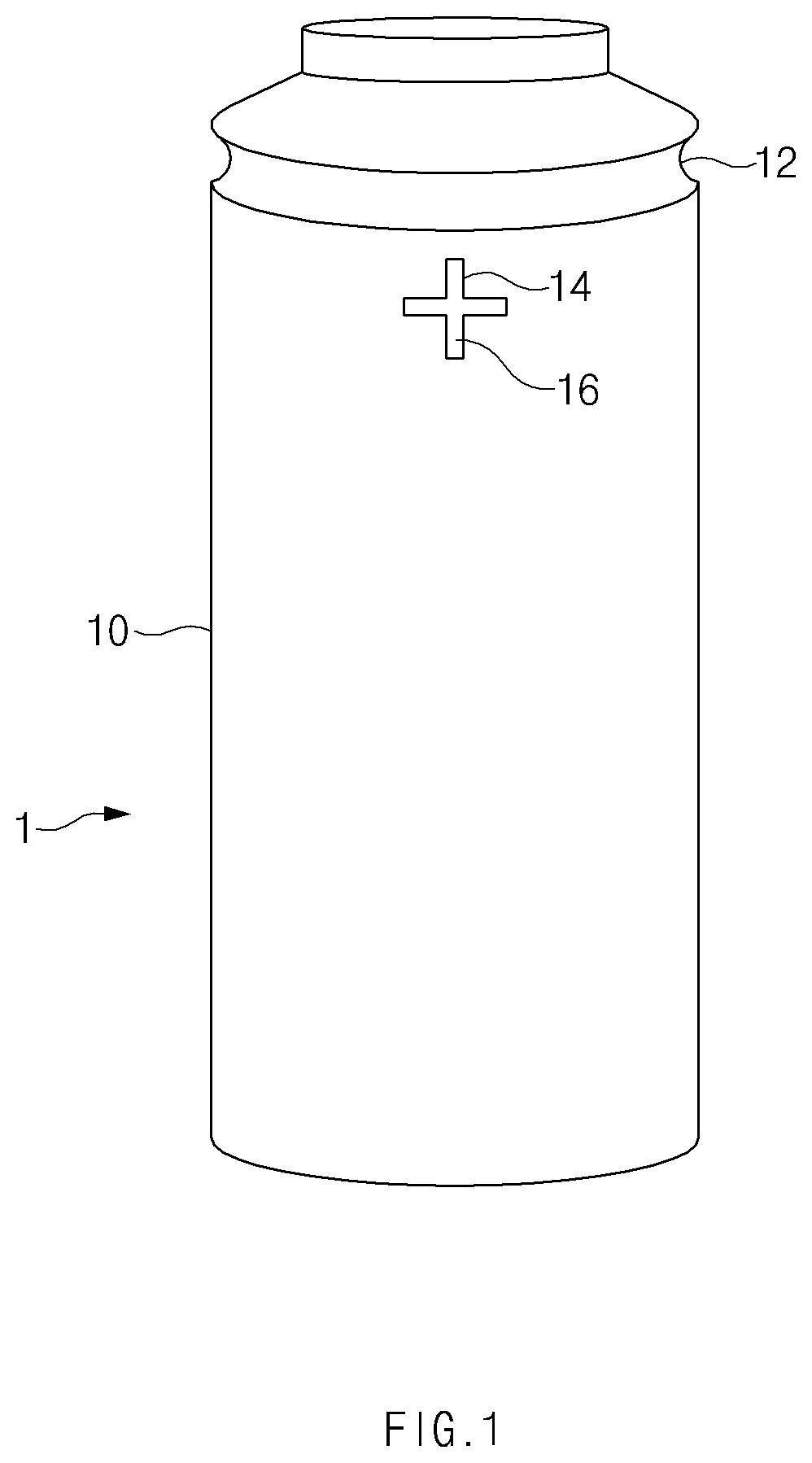
FIG. 1 is a side view illustrating a structure of a secondary battery according to an embodiment of the present invention.
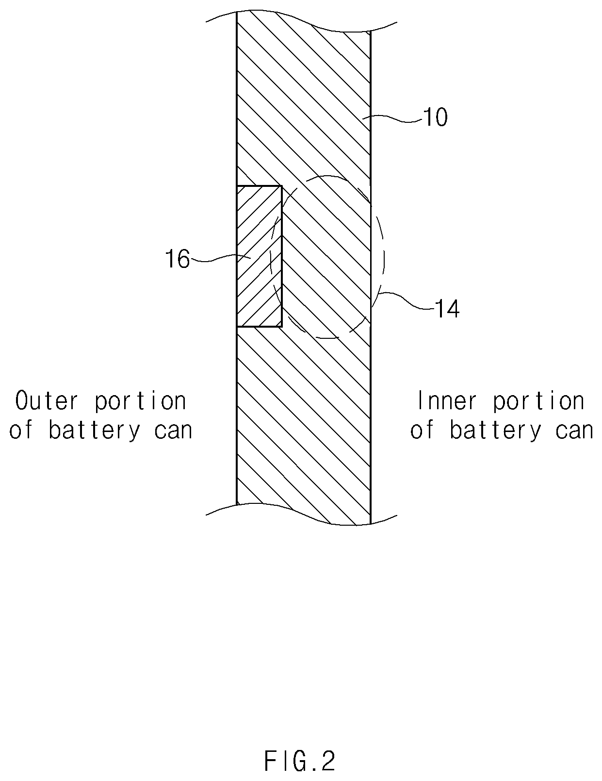
FIG. 2 is an enlarged side cross-sectional view of a region in which a slim part and a coating part are formed in the secondary battery according to an embodiment of the present invention.
MODE FOR CARRYING OUT THE INVENTION
Hereinafter, a structure of a secondary battery according to the present invention will be described with reference to the accompanying drawings.
FIG. 1 is a side view illustrating a structure of a secondary battery according to an embodiment of the present invention, and FIG. 2 is an enlarged side cross-sectional view of a region in which a slim part and a coating part are formed in the secondary battery according to an embodiment of the present invention.
A secondary battery according to the present invention may be a can-type secondary battery or a cylindrical secondary battery.
Referring to FIGS. 1 and 2, a secondary battery 1 according to an embodiment of the present invention may include a battery can 10 forming a main body of the secondary battery 1. An electrode assembly (not shown) including an electrode and a separator may be accommodated in the battery can 10.
A beading part 12 provided in an upper portion of the battery can 10 and having a shape that is recessed inward may be formed in the battery can 10 of the secondary battery 1.
Continuously referring to FIGS. 1 and 2, the battery can 10 of the secondary battery 1 according to an embodiment of the present invention may include a slim part 14 having a relatively thinner thickness than that of the other region of the battery case 10. Other region of the battery can 10 except for the slim part 14 may have a uniform thickness and also have a thickness thicker than that of the slim part 14.
As illustrated in FIGS. 1 and 2, the slim part 14 may have a shape that is recessed inward from an outer surface of the battery can 10 when viewed from the outside. However, alternatively, the slim part 14 may have a shape that is recessed outward from an inner surface of the battery can 10. That is, the slim part 14 of the secondary battery 1 according to another embodiment of the present invention may have a shape that is recessed to the inside of the battery can 10.
According to an embodiment of the present invention, since the battery can 10 of the secondary battery 1 includes the slim part 14 having the relatively thinner thickness than that of the other region. Thus, when a pressure within the secondary battery 1 abnormally increases due to ignition or explosion of the secondary battery, the slim part 14 having the relatively thin thickness may be ruptured first to quickly discharge a gas and materials within the secondary battery.
Particularly, according to the related art, the safety vent for discharging the gas within the secondary battery to the outside has been frequently provided for the safety of the secondary battery. However, when the secondary battery is ignited, a path for discharging the gas may be blocked by the electrode or the separator within the secondary battery during the combustion. Thus, the gas or materials may not be smoothly discharged. However, according to the present invention, since the slim part is formed in the side surface of the secondary battery, even though the secondary battery is ignited, the gas or materials within the secondary battery may be smoothly discharged.
Continuously referring to FIGS. 1 and 2, the slim part 14 according to an embodiment of the present invention has a shape of which at least two surfaces extending in different directions cross each other. FIG. 1 illustrates a case in which the slim part 14 has a cross shape in which two surfaces cross each other to form one crossing region. However, the embodiment of the present invention is not limited thereto. For example, the slim part 14 may have three or more surfaces crossing each other to form two or more crossing regions. Alternatively, the slim part 14 may have a shape in which two or more surfaces radially cross each other.
Also, the region in which at least two surfaces cross each other in the slim part 14 may have a thickness less than that of a region except for the region in which the at least two surfaces cross each other.
According to the present invention, the slim part 14 may have a shape in which at least two surfaces extending in different directions cross each other. Since the region in which the two or more surfaces cross each other has a thickness less than that of a region except for the region in which the two or more surfaces cross each other, when the rupture occurs in the region in which the two or more surfaces cross each other, the rupture may be expanded to the region in which the two or more surfaces do not cross each other, and thus, a more amount of gas may be quickly discharged. Also, since a large amount of gas within the secondary battery is discharged through the rupture part in various directions, the gas within the secondary battery may be effectively discharged.
The slim part may be disposed on a lower portion of the beading part 12. Particularly, as illustrated in FIG. 1, the slim part 14 may be disposed between the beading part 12 and the central portion of the battery can 10. In the case of the cylindrical battery, when the safety vent for discharging the gas in an emergency due to the increase in pressure within the secondary battery is generally provided on the upper portion of the secondary battery. Even though the safety vent is ruptured in the emergency due to the increase in pressure within the secondary battery, the region in which the rupture occurs may be blocked by foreign substances within the secondary battery. In this case, the risk of explosion of the secondary battery increases. According to the present invention, since the slim part 14 is disposed between the beading part 12 and the central portion of the battery can 10, i.e., in the upper portion of the secondary battery, if the safety vent provided in the upper portion of the secondary battery does not play a role, the gases filled in the upper portion of the secondary battery may be discharged through the ruptured slim part 14.
A ratio of a thickness of the slim part 14 to a thickness of the other adjacent region except for the slim part in the battery can 10 may be 0.6 to 0.7. Preferably, a ratio of a thickness of the slim part 14 to a thickness of the other adjacent region except for the slim part in the battery can 10 may be 0.65 to 0.68. When the slim part 14 has a thickness less than that of the other region, i.e., the ratio of the thickness of the slim part 14 to the thickness of the other region is less than 0.6, the rupture may occur in the slim part even though the pressure within the secondary battery is in a normal state. On the other hand, when the slim part 14 has a thickness greater than that of the other region adjacent to the slim part 14, i.e., the ratio of the thickness of the slim part 14 to the thickness of the other region exceeds 0.7, the rupture may not occur in the slim part even through the pressure within the secondary battery abnormally increases.
For example, the slim part 14 has a thickness ranging from 0.09 mm to 0.11 mm, and the other region adjacent to the slim part 14 in the secondary battery 10 may have a thickness ranging from 0.14 mm to 0.16 mm.
The secondary battery according to an embodiment of the present invention may further include a coating part 16 applied to the battery can 10. Here, the coating part 16 may be applied to the slim part 14 and have tensile strength less than that of the slim part 14. Also, the sum of the thickness of the slim part 14 and the thickness of the coating part 16 may be substantially the same as that of the other region of the battery can 10. Like the slim part 14, the coating part 16 may also be disposed below the beading part 12. For example, the coating part 16 may be disposed between the beading part 12 and the central portion of the battery can 10.
Also, as described above, the slim part 14 may be disposed on an outer portion of the battery can 10 or in an inner portion of the battery can 10. In addition, the coating part 16 may also be disposed on the outer portion of the battery can 10 or in the inner portion of the battery can 10.
According to the present invention, the coating part 16 may reinforce the region of the battery can 10, in which the slim part 14 is formed. That is, since the coating part is formed on the slim part, when the slim part is formed in the inner portion of the battery can, the coating part may protect the slim part against the electrode assembly or an electrolyte. When the slim part is formed on the outer portion of the battery can, the coating part may prevent the slim part from being damaged or corroding due to external foreign substances inserted into the slim part while protecting the slim part against external environments or external objects. However, even in this case, the coating part may have tensile strength less than that of the slim part so that the function of the slim part that is ruptured to discharge the gas to the outside is continuously maintained. However, if the coating part 16 is made of a material having tensile strength greater than that of the slim part 14, the occurrence of the rupture in the slim part may be interrupted. Thus, it may be preferable that the coating part is made of a material having tensile strength less than that of the slim part. Particularly, it may be preferable that the coating part is made of a metal material having tensile strength less than that of the slim part.
Here, the tensile strength of the coating part to the tensile strength of the slim part may be 0.5 to 0.7. More preferably, the tensile strength of the coating part to the tensile strength of the slim part may be 0.55 to 0.65.
When the coating part has too low tensile strength, the effect of the coating part that protects the secondary battery against the external impact may be deteriorated. On the other hand, when the slim part 14 has a too thick thickness, the rupture may not occur in the coating part even through the pressure within the secondary battery abnormally increases.
For example, the coating part 16 may have tensile strength of 150 Mpa to 200 Mpa. More preferably, the coating part 16 may have tensile strength of 170 Mpa to 180 Mpa.
The battery can of the secondary battery according to the present invention may be can made of nickel. The coating part 16 according to the present invention may be made of a material having tensile strength less than that of nickel.
The battery can 10 of the secondary battery according to the present invention may be made of a metal material, for example, nickel, steel use stainless (SUS), or an alloy thereof, preferably, may be made of SUS.
The coating part 16 of the secondary battery according to the present invention may be made of a metal material, for example, an aluminum material. For example, the coating part 16 may be made of an aluminum alloy. Here, the aluminum alloy used for the coating part 16 may contain aluminum at a weight ratio of 98% to 99% and manganese at a weight ratio of 1% to 2%. The aluminum alloy used for the coating part 16 may be A1 3003.
As described above, when the coating part 16 of the secondary battery is made of the metal material, the rupture of the slim part due to the increase in pressure within the secondary battery may be smoothly uniformly performed over the entire region of the slim part as compared with the case in which the coating part 16 is made of a resin material such as a fluorine resin or a poly-olefin resin.
The alloy generally has relatively higher thermal conductivity than that of the resin. Particularly, the aluminum alloy may have thermal conductivity that is remarkably higher than that of the resin. Here, when a temperature and pressure within the secondary battery increase due to the abnormal state within the secondary battery, the heat within the secondary battery may be transmitted to the coating part. As a result, the heat within the secondary battery may be uniformly transmitted to the entire region of the coating part to quickly cause the rupture. On the other hand, in the case of the resin material, since the thermal conductivity is lowered, when a sharp temperature change such as ignition occurs in the secondary battery, heat may be concentrated into a local region, and thus, the resin may be melted or thermally deformed. When the resin is melted or thermally deformed as described above, the rupture part may be blocked by the melted resin, or the rupture may be delayed.
While the embodiments of the present invention have been described with reference to the specific embodiments, it will be apparent to those skilled in the art that various changes and modifications may be made without departing from the spirit and scope of the invention as defined in the following claims.
* * * * *
D00000
D00001
D00002
XML
uspto.report is an independent third-party trademark research tool that is not affiliated, endorsed, or sponsored by the United States Patent and Trademark Office (USPTO) or any other governmental organization. The information provided by uspto.report is based on publicly available data at the time of writing and is intended for informational purposes only.
While we strive to provide accurate and up-to-date information, we do not guarantee the accuracy, completeness, reliability, or suitability of the information displayed on this site. The use of this site is at your own risk. Any reliance you place on such information is therefore strictly at your own risk.
All official trademark data, including owner information, should be verified by visiting the official USPTO website at www.uspto.gov. This site is not intended to replace professional legal advice and should not be used as a substitute for consulting with a legal professional who is knowledgeable about trademark law.