Method and apparatus for emission guided radiation therapy
Mazin March 30, 2
U.S. patent number 10,959,686 [Application Number 16/425,416] was granted by the patent office on 2021-03-30 for method and apparatus for emission guided radiation therapy. This patent grant is currently assigned to RefleXion Medical, Inc.. The grantee listed for this patent is RefleXion Medical, Inc.. Invention is credited to Samuel Mazin.


| United States Patent | 10,959,686 |
| Mazin | March 30, 2021 |
Method and apparatus for emission guided radiation therapy
Abstract
An apparatus comprising a radiation source, coincident positron emission detectors configured to detect coincident positron annihilation emissions originating within a coordinate system, and a controller coupled to the radiation source and the coincident position emission detectors, the controller configured to identify coincident positron annihilation emission paths intersecting one or more volumes in the coordinate system and align the radiation source along an identified coincident positron annihilation emission path.
| Inventors: | Mazin; Samuel (Menlo Park, CA) | ||||||||||
|---|---|---|---|---|---|---|---|---|---|---|---|
| Applicant: |
|
||||||||||
| Assignee: | RefleXion Medical, Inc.
(Hayward, CA) |
||||||||||
| Family ID: | 1000005451695 | ||||||||||
| Appl. No.: | 16/425,416 | ||||||||||
| Filed: | May 29, 2019 |
Prior Publication Data
| Document Identifier | Publication Date | |
|---|---|---|
| US 20190357859 A1 | Nov 28, 2019 | |
Related U.S. Patent Documents
| Application Number | Filing Date | Patent Number | Issue Date | ||
|---|---|---|---|---|---|
| 15807383 | Nov 8, 2017 | 10327716 | |||
| 14951194 | Nov 21, 2017 | 9820700 | |||
| 14278973 | Dec 8, 2015 | 9205281 | |||
| 13895255 | Jun 10, 2014 | 8748825 | |||
| 13209275 | Jun 11, 2013 | 8461538 | |||
| 12367679 | Sep 13, 2011 | 8017915 | |||
| 61036709 | Mar 14, 2008 | ||||
| Current U.S. Class: | 1/1 |
| Current CPC Class: | A61N 5/1081 (20130101); A61B 6/541 (20130101); A61B 6/469 (20130101); A61B 6/0407 (20130101); A61B 6/037 (20130101); A61N 5/1067 (20130101); G01T 1/2978 (20130101); G01T 1/2985 (20130101); A61B 6/54 (20130101); A61N 2005/109 (20130101); A61N 2005/1089 (20130101); A61N 2005/1091 (20130101); A61N 2005/1052 (20130101); A61N 2005/1074 (20130101); A61N 2005/1072 (20130101); A61N 2005/1087 (20130101) |
| Current International Class: | G01T 1/29 (20060101); A61B 6/03 (20060101); A61B 6/00 (20060101); A61N 5/10 (20060101); A61B 6/04 (20060101) |
References Cited [Referenced By]
U.S. Patent Documents
| 3418475 | December 1968 | Hudgens |
| 3668399 | June 1972 | Cahill et al. |
| 3794840 | February 1974 | Scott |
| 3869615 | March 1975 | Hoover et al. |
| 3906233 | September 1975 | Vogel |
| 4361902 | November 1982 | Brandt et al. |
| 4389569 | June 1983 | Hattori et al. |
| 4503331 | March 1985 | Kovacs, Jr. et al. |
| 4529882 | July 1985 | Lee |
| 4563582 | January 1986 | Mullani |
| 4575868 | March 1986 | Ueda et al. |
| 4628499 | December 1986 | Hammett |
| 4642464 | February 1987 | Mullani |
| 4647779 | March 1987 | Wong |
| 4677299 | June 1987 | Wong |
| 4771785 | September 1988 | Duer |
| 4868844 | September 1989 | Nunan |
| 5075554 | December 1991 | Yunker et al. |
| 5099505 | March 1992 | Seppi et al. |
| 5117445 | May 1992 | Seppi et al. |
| 5168532 | December 1992 | Seppi et al. |
| 5206512 | April 1993 | Iwao |
| 5207223 | May 1993 | Adler |
| 5272344 | December 1993 | Williams |
| 5317616 | May 1994 | Swerdloff et al. |
| 5329567 | July 1994 | Ikebe |
| 5351280 | September 1994 | Swerdloff et al. |
| 5390225 | February 1995 | Hawman |
| 5394452 | February 1995 | Swerdloff |
| 5396534 | March 1995 | Thomas |
| 5418827 | May 1995 | Deasy et al. |
| 5442675 | August 1995 | Swerdloff et al. |
| 5548627 | August 1996 | Swerdloff |
| 5661773 | August 1997 | Swerdloff |
| 5668371 | September 1997 | Deasy et al. |
| 5724400 | March 1998 | Swerdloff |
| 5751781 | May 1998 | Brown et al. |
| 5813985 | September 1998 | Carroll |
| 5818902 | October 1998 | Yu |
| 5851182 | December 1998 | Sahadevan |
| 5889834 | March 1999 | Vilsmeier et al. |
| 5937028 | August 1999 | Tybinkowski et al. |
| 5946425 | August 1999 | Bove, Jr. et al. |
| 6023494 | February 2000 | Senzig et al. |
| 6180943 | January 2001 | Lange |
| 6184530 | February 2001 | Hines et al. |
| 6188748 | February 2001 | Pastyr et al. |
| 6255655 | July 2001 | McCroskey et al. |
| 6260005 | July 2001 | Yang et al. |
| 6271517 | August 2001 | Kroening, Jr. et al. |
| 6281505 | August 2001 | Hines et al. |
| 6385288 | May 2002 | Kanematsu |
| 6396902 | May 2002 | Tybinkowski et al. |
| 6438202 | August 2002 | Olivera et al. |
| 6449331 | September 2002 | Nutt et al. |
| 6449340 | September 2002 | Tybinkowski et al. |
| 6455856 | September 2002 | Gagnon |
| 6459769 | October 2002 | Cosman |
| 6504899 | January 2003 | Pugachev et al. |
| 6560311 | May 2003 | Shepard et al. |
| 6618467 | September 2003 | Ruchala et al. |
| 6624451 | September 2003 | Ashley et al. |
| 6628744 | September 2003 | Luhta et al. |
| 6661866 | December 2003 | Limkeman et al. |
| 6661870 | December 2003 | Kapatoes et al. |
| 6696694 | February 2004 | Pastyr et al. |
| 6700949 | March 2004 | Susami et al. |
| 6714076 | March 2004 | Kalb |
| 6730924 | May 2004 | Pastyr et al. |
| 6735277 | May 2004 | McNutt et al. |
| 6778636 | August 2004 | Andrews |
| 6792078 | September 2004 | Kato et al. |
| 6794653 | September 2004 | Wainer et al. |
| 6810103 | October 2004 | Tybinkowski et al. |
| 6810108 | October 2004 | Clark et al. |
| 6831961 | December 2004 | Tybinkowski et al. |
| 6865254 | March 2005 | Nafstadius |
| 6888919 | May 2005 | Graf |
| 6914959 | July 2005 | Bailey et al. |
| 6934363 | August 2005 | Seufert |
| 6965661 | November 2005 | Kojima et al. |
| 6976784 | December 2005 | Kojima et al. |
| 6990175 | January 2006 | Nakashima et al. |
| 7020233 | March 2006 | Tybinkowski et al. |
| 7026622 | April 2006 | Kojima et al. |
| 7110808 | September 2006 | Adair |
| 7129495 | October 2006 | Williams et al. |
| 7154096 | December 2006 | Amano |
| 7167542 | January 2007 | Juschka et al. |
| 7188999 | March 2007 | Mihara et al. |
| 7199382 | April 2007 | Rigney et al. |
| 7227925 | June 2007 | Mansfield et al. |
| 7242750 | July 2007 | Tsujita |
| 7263165 | August 2007 | Ghelmansarai |
| 7265356 | September 2007 | Pelizzari et al. |
| 7280633 | October 2007 | Cheng et al. |
| 7291840 | November 2007 | Fritzler et al. |
| 7297958 | November 2007 | Kojima et al. |
| 7298821 | November 2007 | Ein-Gal |
| 7301144 | November 2007 | Williams et al. |
| 7302038 | November 2007 | Mackie |
| 7310410 | December 2007 | Sohal et al. |
| 7331713 | February 2008 | Moyers |
| 7338207 | March 2008 | Gregerson et al. |
| 7386099 | June 2008 | Kasper et al. |
| 7397901 | July 2008 | Johnsen |
| 7397902 | July 2008 | Seeber et al. |
| 7405404 | July 2008 | Shah |
| 7412029 | August 2008 | Myles |
| 7433503 | October 2008 | Cherek et al. |
| 7439509 | October 2008 | Grazioso et al. |
| 7446328 | November 2008 | Rigney et al. |
| 7453983 | November 2008 | Schildkraut et al. |
| 7453984 | November 2008 | Chen et al. |
| 7469035 | December 2008 | Keall et al. |
| 7545911 | June 2009 | Rietzel et al. |
| 7555103 | June 2009 | Johnsen |
| 7558378 | July 2009 | Juschka et al. |
| 7560698 | July 2009 | Rietzel |
| 7564951 | July 2009 | Hasegawa et al. |
| 7596209 | September 2009 | Perkins |
| 7627082 | December 2009 | Kojima et al. |
| 7639853 | December 2009 | Olivera et al. |
| 7656999 | February 2010 | Hui et al. |
| 7657304 | February 2010 | Mansfield et al. |
| 7679049 | March 2010 | Rietzel |
| 7715606 | May 2010 | Jeung et al. |
| 7742575 | June 2010 | Bourne |
| 7755054 | July 2010 | Shah et al. |
| 7755055 | July 2010 | Schilling |
| 7755057 | July 2010 | Kim |
| 7778691 | August 2010 | Zhang et al. |
| 7792252 | September 2010 | Bohn |
| 7795590 | September 2010 | Takahashi et al. |
| 7800070 | September 2010 | Weinberg et al. |
| 7820975 | October 2010 | Laurence et al. |
| 7839972 | November 2010 | Ruchala et al. |
| 7847274 | December 2010 | Kornblau et al. |
| 7885371 | February 2011 | Thibault |
| 7942843 | May 2011 | Tune et al. |
| 7952079 | May 2011 | Neustadter et al. |
| 7957507 | June 2011 | Cadman |
| 7965819 | June 2011 | Nagata |
| 7983380 | July 2011 | Guertin |
| 8019042 | September 2011 | Shukla et al. |
| 8059782 | November 2011 | Brown |
| 8063376 | November 2011 | Maniawski et al. |
| 8090074 | January 2012 | Filiberti et al. |
| 8093568 | January 2012 | Mackie |
| 8116427 | February 2012 | Kojima et al. |
| 8139713 | March 2012 | Janbakhsh |
| 8139714 | March 2012 | Sahadevan |
| 8144962 | March 2012 | Busch et al. |
| 8148695 | April 2012 | Takahashi et al. |
| 8160205 | April 2012 | Saracen |
| 8193508 | June 2012 | Shchory et al. |
| 8198600 | June 2012 | Neustadter et al. |
| 8232535 | July 2012 | Olivera et al. |
| 8239002 | August 2012 | Neustadter et al. |
| 8269195 | September 2012 | Rigney et al. |
| 8278633 | October 2012 | Nord et al. |
| 8280002 | October 2012 | Bani-Hashemi et al. |
| 8295906 | October 2012 | Saunders et al. |
| 8304738 | November 2012 | Gagnon et al. |
| 8306185 | November 2012 | Bal et al. |
| 8335296 | December 2012 | Dehler et al. |
| 8357903 | January 2013 | Wang et al. |
| 8384049 | February 2013 | Broad |
| 8395127 | March 2013 | Frach et al. |
| 8406844 | March 2013 | Ruchala et al. |
| 8406851 | March 2013 | West et al. |
| 8442287 | May 2013 | Fordyce, II et al. |
| 8461538 | June 2013 | Mazin |
| 8461539 | June 2013 | Yamaya et al. |
| 8467497 | June 2013 | Lu et al. |
| 8483803 | July 2013 | Partain et al. |
| 8509383 | August 2013 | Lu et al. |
| 8520800 | August 2013 | Wilfley et al. |
| 8536547 | September 2013 | Maurer, Jr. et al. |
| 8537373 | September 2013 | Humphrey |
| 8581196 | November 2013 | Yamaya et al. |
| 8588367 | November 2013 | Busch et al. |
| 8617422 | December 2013 | Koschan et al. |
| 8641592 | February 2014 | Yu |
| 8664610 | March 2014 | Chuang |
| 8664618 | March 2014 | Yao |
| 8712012 | April 2014 | O'Connor |
| 8745789 | June 2014 | Saracen |
| 8748825 | June 2014 | Mazin |
| 8767917 | July 2014 | Ruchala et al. |
| 8816307 | August 2014 | Kuusela et al. |
| 8873710 | October 2014 | Ling et al. |
| 8884240 | November 2014 | Shah et al. |
| 8992404 | March 2015 | Graf et al. |
| 9061141 | June 2015 | Brunker et al. |
| 9179982 | November 2015 | Kunz et al. |
| 9205281 | December 2015 | Mazin |
| 9360570 | June 2016 | Rothfuss et al. |
| 9370672 | June 2016 | Parsai et al. |
| 9437339 | September 2016 | Echner |
| 9437340 | September 2016 | Echner et al. |
| 9498167 | November 2016 | Bechtel et al. |
| 9649509 | May 2017 | Mazin et al. |
| 9694208 | July 2017 | Mazin et al. |
| 9697980 | July 2017 | Ogura et al. |
| 9731148 | August 2017 | Olivera et al. |
| 9820700 | November 2017 | Mazin |
| 9878180 | January 2018 | Schulte et al. |
| 9886534 | February 2018 | Wan et al. |
| 9952878 | April 2018 | Grimme et al. |
| 9974494 | May 2018 | Mostafavi et al. |
| 10159853 | December 2018 | Kuusela et al. |
| 10327716 | June 2019 | Mazin |
| 10478133 | November 2019 | Levy et al. |
| 10603515 | March 2020 | Olcott et al. |
| 10695586 | June 2020 | Harper et al. |
| 10745253 | August 2020 | Saracen |
| 2002/0051513 | May 2002 | Pugachev et al. |
| 2002/0148970 | October 2002 | Wong et al. |
| 2002/0163994 | November 2002 | Jones |
| 2002/0191734 | December 2002 | Kojima et al. |
| 2002/0193685 | December 2002 | Mate et al. |
| 2003/0036700 | February 2003 | Weinberg |
| 2003/0080298 | May 2003 | Karplus et al. |
| 2003/0105397 | June 2003 | Tumer et al. |
| 2003/0128801 | July 2003 | Eisenberg et al. |
| 2003/0219098 | November 2003 | McNutt et al. |
| 2004/0024300 | February 2004 | Graf |
| 2004/0030246 | February 2004 | Townsend et al. |
| 2004/0037390 | February 2004 | Mihara et al. |
| 2004/0057557 | March 2004 | Nafstadius |
| 2004/0096033 | May 2004 | Seppi et al. |
| 2004/0120452 | June 2004 | Shapiro et al. |
| 2004/0158416 | August 2004 | Slates |
| 2004/0162457 | August 2004 | Maggiore |
| 2004/0264640 | December 2004 | Myles |
| 2005/0028279 | February 2005 | de Mooy |
| 2005/0089135 | April 2005 | Toth et al. |
| 2005/0104001 | May 2005 | Shah |
| 2005/0109939 | May 2005 | Engler et al. |
| 2005/0197564 | September 2005 | Dempsey |
| 2005/0213705 | September 2005 | Hoffman |
| 2005/0228255 | October 2005 | Saracen |
| 2005/0234327 | October 2005 | Saracen |
| 2006/0002511 | January 2006 | Miller et al. |
| 2006/0072699 | April 2006 | Mackie |
| 2006/0113482 | June 2006 | Pelizzari et al. |
| 2006/0124854 | June 2006 | Shah |
| 2006/0173294 | August 2006 | Ein-Gal |
| 2006/0182326 | August 2006 | Schildkraut et al. |
| 2006/0193435 | August 2006 | Hara et al. |
| 2006/0208195 | September 2006 | Petrick et al. |
| 2006/0237652 | October 2006 | Kimchy et al. |
| 2007/0003010 | January 2007 | Guertin et al. |
| 2007/0003123 | January 2007 | Fu et al. |
| 2007/0014391 | January 2007 | Mostafavi et al. |
| 2007/0023669 | February 2007 | Hefetz et al. |
| 2007/0025513 | February 2007 | Ghelmansarai |
| 2007/0043289 | February 2007 | Adair |
| 2007/0053491 | March 2007 | Schildkraut et al. |
| 2007/0055144 | March 2007 | Neustadter et al. |
| 2007/0164239 | July 2007 | Terwilliger et al. |
| 2007/0211857 | September 2007 | Urano et al. |
| 2007/0221869 | September 2007 | Song |
| 2007/0265528 | November 2007 | Xu |
| 2007/0270693 | November 2007 | Fiedler et al. |
| 2008/0002811 | January 2008 | Allison |
| 2008/0031404 | February 2008 | Khamene |
| 2008/0031406 | February 2008 | Yan et al. |
| 2008/0043910 | February 2008 | Thomas |
| 2008/0103391 | May 2008 | Dos Santos |
| 2008/0128631 | June 2008 | Suhami |
| 2008/0130825 | June 2008 | Fu et al. |
| 2008/0152085 | June 2008 | Saracen et al. |
| 2008/0156993 | July 2008 | Weinberg et al. |
| 2008/0203309 | August 2008 | Frach et al. |
| 2008/0205588 | August 2008 | Kim |
| 2008/0214927 | September 2008 | Cherry et al. |
| 2008/0217541 | September 2008 | Kim |
| 2008/0230705 | September 2008 | Rousso et al. |
| 2008/0253516 | October 2008 | Hui et al. |
| 2008/0262473 | October 2008 | Kornblau et al. |
| 2008/0273659 | November 2008 | Guertin |
| 2008/0298536 | December 2008 | Ein-Gal |
| 2009/0003655 | January 2009 | Wollenweber |
| 2009/0086909 | April 2009 | Hui et al. |
| 2009/0116616 | May 2009 | Lu |
| 2009/0131734 | May 2009 | Neustadter et al. |
| 2009/0169082 | July 2009 | Mizuta et al. |
| 2009/0236532 | September 2009 | Frach et al. |
| 2009/0256078 | October 2009 | Mazin |
| 2009/0309046 | December 2009 | Balakin |
| 2010/0010343 | January 2010 | Daghighian et al. |
| 2010/0040197 | February 2010 | Maniawski |
| 2010/0054412 | March 2010 | Brinks et al. |
| 2010/0063384 | March 2010 | Kornblau et al. |
| 2010/0065723 | March 2010 | Burbar et al. |
| 2010/0067660 | March 2010 | Maurer, Jr. et al. |
| 2010/0069742 | March 2010 | Partain et al. |
| 2010/0074400 | March 2010 | Sendai |
| 2010/0074498 | March 2010 | Breeding |
| 2010/0166274 | July 2010 | Busch et al. |
| 2010/0176309 | July 2010 | Mackie |
| 2010/0198063 | August 2010 | Huber |
| 2010/0237259 | September 2010 | Wang |
| 2011/0006212 | January 2011 | Shchory et al. |
| 2011/0044429 | February 2011 | Takahashi et al. |
| 2011/0073763 | March 2011 | Subbarao |
| 2011/0092814 | April 2011 | Yamaya et al. |
| 2011/0105895 | May 2011 | Kornblau et al. |
| 2011/0105897 | May 2011 | Kornblau et al. |
| 2011/0118588 | May 2011 | Kornblau et al. |
| 2011/0198504 | August 2011 | Eigen |
| 2011/0215248 | September 2011 | Lewellen et al. |
| 2011/0215259 | September 2011 | Iwata |
| 2011/0272600 | November 2011 | Bert et al. |
| 2011/0297833 | December 2011 | Takayama |
| 2011/0301449 | December 2011 | Maurer, Jr. |
| 2011/0309252 | December 2011 | Moriyasu |
| 2011/0309255 | December 2011 | Bert et al. |
| 2011/0313231 | December 2011 | Guertin et al. |
| 2011/0313232 | December 2011 | Balakin |
| 2012/0035470 | February 2012 | Kuduvalli et al. |
| 2012/0068076 | March 2012 | Daghighian |
| 2012/0138806 | June 2012 | Holmes et al. |
| 2012/0161014 | June 2012 | Yamaya |
| 2012/0174317 | July 2012 | Saracen |
| 2012/0230464 | September 2012 | Ling et al. |
| 2012/0318989 | December 2012 | Park et al. |
| 2012/0323117 | December 2012 | Neustadter et al. |
| 2013/0025055 | January 2013 | Saracen |
| 2013/0060134 | March 2013 | Eshima |
| 2013/0092842 | April 2013 | Zhang et al. |
| 2013/0111668 | May 2013 | Wiggers et al. |
| 2013/0193330 | August 2013 | Wagadarikar et al. |
| 2013/0266116 | October 2013 | Abenaim et al. |
| 2013/0327932 | December 2013 | Kim et al. |
| 2013/0343509 | December 2013 | Gregerson et al. |
| 2014/0029715 | January 2014 | Hansen et al. |
| 2014/0107390 | April 2014 | Brown et al. |
| 2014/0163368 | June 2014 | Rousso |
| 2014/0184197 | July 2014 | Dolinsky |
| 2014/0193336 | July 2014 | Rousso |
| 2014/0217294 | August 2014 | Rothfuss |
| 2014/0224963 | August 2014 | Guo et al. |
| 2014/0228613 | August 2014 | Mazin et al. |
| 2014/0239204 | August 2014 | Orton et al. |
| 2014/0257096 | September 2014 | Prevrhal |
| 2015/0018673 | January 2015 | Rose et al. |
| 2015/0076357 | March 2015 | Frach |
| 2015/0078528 | March 2015 | Okada |
| 2015/0168567 | June 2015 | Kim et al. |
| 2015/0177394 | June 2015 | Dolinsky et al. |
| 2015/0190658 | July 2015 | Yu |
| 2015/0276947 | October 2015 | Hoenk et al. |
| 2015/0285922 | October 2015 | Mintzer et al. |
| 2016/0023019 | January 2016 | Filiberti et al. |
| 2016/0073977 | March 2016 | Mazin |
| 2016/0097866 | April 2016 | Williams |
| 2016/0146949 | May 2016 | Frach et al. |
| 2016/0209515 | July 2016 | Da Silva et al. |
| 2016/0219686 | July 2016 | Nakayama et al. |
| 2016/0266260 | September 2016 | Preston |
| 2016/0273958 | September 2016 | Hoenk et al. |
| 2016/0299240 | October 2016 | Cho et al. |
| 2016/0361566 | December 2016 | Larkin et al. |
| 2016/0374632 | December 2016 | David |
| 2017/0014648 | January 2017 | Mostafavi |
| 2017/0052266 | February 2017 | Kim et al. |
| 2017/0220709 | August 2017 | Wan et al. |
| 2017/0242136 | August 2017 | O'Neill et al. |
| 2017/0281975 | October 2017 | Filiberti et al. |
| 2018/0133518 | May 2018 | Harper et al. |
| 2018/0292550 | October 2018 | Xu et al. |
| 2019/0018154 | January 2019 | Olcott et al. |
| 2019/0070437 | March 2019 | Olcott et al. |
| 2019/0143145 | May 2019 | Laurence, Jr. et al. |
| 2020/0215355 | July 2020 | Olcott et al. |
| 2020/0222724 | July 2020 | Mazin et al. |
| 1681436 | Oct 2005 | CN | |||
| 1960780 | May 2007 | CN | |||
| 101970043 | Feb 2011 | CN | |||
| 10-2008-053321 | May 2010 | DE | |||
| 1 501 604 | Dec 2009 | EP | |||
| 1 698 234 | Apr 2010 | EP | |||
| 2 188 815 | Nov 2011 | EP | |||
| 2 687 259 | Jan 2014 | EP | |||
| 2 874 702 | Sep 2016 | EP | |||
| 1 664 752 | Jun 2017 | EP | |||
| 208396 | Dec 2010 | IL | |||
| 09-33658 | Feb 1997 | JP | |||
| 9-189769 | Jul 1997 | JP | |||
| H-11-290466 | Oct 1999 | JP | |||
| 2000-105279 | Apr 2000 | JP | |||
| 2001-340474 | Dec 2001 | JP | |||
| 2003-534823 | Nov 2003 | JP | |||
| 2004-513735 | May 2004 | JP | |||
| 2006-145281 | Jun 2006 | JP | |||
| 2007-502166 | Feb 2007 | JP | |||
| 2007-507246 | Mar 2007 | JP | |||
| 2008-173299 | Jul 2008 | JP | |||
| 2010-517655 | May 2010 | JP | |||
| 9520013 | Feb 1997 | NL | |||
| WO-89/10090 | Nov 1989 | WO | |||
| WO-95/22241 | Aug 1995 | WO | |||
| WO-00/15299 | Mar 2000 | WO | |||
| WO-03/076003 | Sep 2003 | WO | |||
| WO-03/076003 | Sep 2003 | WO | |||
| WO-2004/017832 | Mar 2004 | WO | |||
| WO-2004/017832 | Mar 2004 | WO | |||
| WO-2004/105574 | Dec 2004 | WO | |||
| WO-2004/105574 | Dec 2004 | WO | |||
| WO-2005/018734 | Mar 2005 | WO | |||
| WO-2005/018734 | Mar 2005 | WO | |||
| WO-2005/018735 | Mar 2005 | WO | |||
| WO-2005/018735 | Mar 2005 | WO | |||
| WO-2005/110495 | Nov 2005 | WO | |||
| WO-2007/045076 | Apr 2007 | WO | |||
| WO-2007/094002 | Aug 2007 | WO | |||
| WO-2007/094002 | Aug 2007 | WO | |||
| WO-2007/124760 | Nov 2007 | WO | |||
| WO-2008/011725 | Jan 2008 | WO | |||
| WO-2008/019118 | Feb 2008 | WO | |||
| WO-2008/019118 | Feb 2008 | WO | |||
| WO-2008/024463 | Feb 2008 | WO | |||
| WO-2008/024463 | Feb 2008 | WO | |||
| WO-2009/111580 | Sep 2009 | WO | |||
| WO-2009/111580 | Sep 2009 | WO | |||
| WO-2009/114117 | Sep 2009 | WO | |||
| WO-2009/114117 | Sep 2009 | WO | |||
| WO-2010/015358 | Feb 2010 | WO | |||
| WO-2010/110255 | Sep 2010 | WO | |||
| WO-2012/135771 | Oct 2012 | WO | |||
| WO-2015/042510 | Mar 2015 | WO | |||
| WO-2016/097977 | Jun 2016 | WO | |||
Other References
|
Chang, J.Y. et al. (2008). "Image-guided radiation therapy for non-small cell lung cancer," J. Thorac. Oncol. 3(2):177-186. cited by applicant . Chen, Y. et al. (2011). Dynamic tomotherapy delivery, Am. Assoc. Phys. Med. 38:3013-3024. cited by applicant . Dieterich, S. et al, (2003), "Skin respiratory motion tracking for stereotactic radiosurgery using the CyberKnife," Elsevier Int'l Congress Series 1256:130-136. cited by applicant . Erdi, Y.E. (2007). "The use of PET for radiotherapy," Curr. Medical Imaging Reviews 3(1):3-16. cited by applicant . Extended European Search Report dated Mar. 31, 2017, for European Application No, 09 719 473.2, filed on Mar. 9, 2009, 8 pages. cited by applicant . Fan, Q. et al. (2012). "Emission Guided Radiation Therapy for Lung and Prostrate Cancers: A Feasibility Study on a Digital Patient," Med. Phys. 39(11):7140-7152. cited by applicant . Fan, Q. et al. (2013). "Toward a Planning Scheme for Emission Guided Radiation Therapy (EGRT): FDG Based Tumor Tracking in a Metastatic Breast Cancer Patient," Med. Phys. 40(8): 12 pages. cited by applicant . Final Office Action dated Aug. 15, 2012, for U.S. Appl. No. 13/209,275, filed Aug. 12, 2011, 8 pages. cited by applicant . Galvin, J.M. (2018). "The muitileaf collimator--A complete guide," 17 total pages. cited by applicant . Gibbons, J.P. (2004). "Dose calculation and verification for tomotherapy," 2004 ACMP Meeting, Scottsdale, AZ., 71 total pages. cited by applicant . Glendinning, A.G. et al. (2001). "Measurement of the response of Gd.sub.2O.sub.2S:Tb phosphor to 6 MV x-rays," Phys. Mol. Biol. 46:517-530. cited by applicant . Handsfield, L.L. et al. (2014). "Phantomless patient-specific TornoTherapy QA via delivery performance monitoring and a secondary Monte Carlo dose calculation," Med. Phys. 41:101703-1-101703-9. cited by applicant . International Search Report dated May 4, 2009, for PCT Application No. PCT/US2009/01500, filed on Mar. 9, 2009, 3 pages. cited by applicant . International Search Report dated Mar. 7, 2018, for PCT Application No. PCT/US2017/061848, filed on Nov. 15, 2017, 4 pages. cited by applicant . International Search Report dated Oct. 2, 2018, for PCT Application No. PCT/US2018/041700, filed Jul. 11, 2018, 2 pages. cited by applicant . International Search Report dated Oct. 24, 2018, for PCT Application No. PCT/US2018/046132, filed Aug. 9, 2018, 2 pages. cited by applicant . International Search Report dated Jan. 30, 2019, for PCT Application No. PCT/US2018/061099, filed on Nov. 14, 2018, 4 pages. cited by applicant . Kapatoes, J.M. et al. (2001). "A feasible method for clinical delivery verification and dose reconstruction in tomotherapy," Med. Phys. 28:528-542. cited by applicant . Keall, P.J. et al. (2001). "Motion adaptive x-ray therapy: a feasibility study," Phys. Med. Biol. 46:1-10. cited by applicant . Kim, H. et al. (2009). "A multi-threshold method for the TOF-PET Signal Processing," Nucl. Instrum. Meth. Phys. Res. A. 602:618-621. cited by applicant . Krouglicof, N. et al. (2013). "Development of a Novel PCB-Based Voice Coil Actuator for Opto-Mechatronic Applications," presented at IEEE/RSJ International Conference on Intelligent Robots and Systems (IROS), Tokyo, Japan, Nov. 3-7, 2013, pp. 5634-5640. cited by applicant . Langen, K.M. et al, (2010). "QA for helical tomotherapy: report of the AAPM Task Group 148," Med. Phys. 37:4817-4853. cited by applicant . Macke, T,R. et al, (Nov.-Dec. 1993). "Tomotherapy: A New Concept for the Delivery of Dynamic Conformal Radiotherapy," Med. Phys. 20(6):1709-1719. cited by applicant . Mazin, S. R. et al. (2010). "Emission-Guided Radiation Therapy: Biologic Targeting arid Adaptive Treatment," Journal of American College of Radiology 7(12):989-990. cited by applicant . Non-Final Office Action dated Jan. 10, 2011, for U.S. Appl. No. 12/367,679, filed Feb. 9, 2009, 9 pages. cited by applicant . Non-Final Office Action dated Feb. 28, 2012, for U.S. Appl. No. 13/209,275, filed Aug. 12, 2011, 8 pages. cited by applicant . Non-Final Office Action dated Sep. 19, 2013, for U.S. Appl. No. 13/895,255, filed May 15, 2013, 8 pages. cited by applicant . Notice of Allowance dated Jul. 25, 2011, for U.S. Appl. No. 12/367,679, filed Feb. 9, 2009, 7 pages. cited by applicant . Notice of Allowance dated Apr. 9, 2014, for U.S. Appl. No. 13/895,255, filed May 15, 2013, 7 pages. cited by applicant . Notice of Allowance dated Oct. 27, 2015, for U.S. Appl. No. 14/278,973, filed May 15, 2014, 8 pages. cited by applicant . Notice of Allowance dated Mar. 27, 2013, for U.S. Appl. No. 13/209,275, filed Aug. 12, 2011, 9 pages. cited by applicant . Notice of Allowance dated Oct. 5, 2017, for U.S. Appl. No. 14/951,194, filed Nov. 24, 2015, 11 pages. cited by applicant . Notice of Allowance dated Apr. 4, 2019, for U.S. Appl. No. 15/807,383, filed Nov. 8, 2017, 11 pages. cited by applicant . North Shore LIJ (2008). IMRT treatment plans: Dosimetry measurements & monitor units validation, 133 total pages. cited by applicant . Papanikolaou, N. et al. (2010). "MU-Tomo: Independent dose validation software for helical tomo therapy," J. Cancer Sci. Ther. 2:145-152. cited by applicant . Parodi, K. (2015). "Vision 20/20: Positron emission tomography in radiation therapy planning, delivery, arid monitoring," Med. Phys. 42:7153-7168. cited by applicant . Prabhakar, R. et al. (2007). "An Insight into PET-CT Based Radiotherapy Treatment Planning," Cancer Therapy (5):519-524. cited by applicant . Schleifring (2013). Slip Ring Solutions--Technology, 8 total pages. cited by applicant . Tashima, H. et al. (2012). "A Single-Ring Open PET Enabling PET Imaging During Radiotherapy," Phys. Med. Biol. 57(14):4705-4718. cited by applicant . TornoTherapy.RTM. (2011). TOMOHD Treatment System, Product Specifications, 12 total pages. cited by applicant . Varian Medical Systems (2004). "Dynamic Targeting.TM. Image-Guided Radiation Therapy--A Revolution in Cancer Care," Business Briefing: US Oncology Review, Abstract only, 2 pages. cited by applicant . Wikipedia (2016), "Scotch yoke," Retrieved from https://en.wikipedia.org/wiki/Scotch_yoke, 3 pages. cited by applicant . Willoughby, T. et al. (2012). "Quality assurance for nonradiographic radiotherapy localization and positioning systems: Report of task group 147" Med. Phys. 39:1728-1747. cited by applicant . Written Opinion of the International Searching Authority dated May 4, 2009, for PCT Application No. PCT/US2009/01500, filed on Mar. 9, 2009, 5 pages. cited by applicant . Written Opinion of the International Searching Authority dated Mar. 7, 2018, for PCT Application No. PCT/US2017/061848, filed Nov. 15, 2017, 5 pages. cited by applicant . Written Opinion of the International Searching Authority dated Oct. 2, 2018, for PCT Application No. PCT/US2018/041700, filed on Jul. 11, 2018, 19 pages. cited by applicant . Written Opinion of the International Searching Authority dated Oct. 24, 2018, for PCT Application No. PCT/US2018/046132, filed on Aug. 9, 2018, 7 pages. cited by applicant . Written Opinion of the International Searching Authority dated Jan. 30, 2019, for PCT Application No. PCT/US2018/061099, filed on Nov. 14, 2018, 11 pages. cited by applicant . Yamaya, T. et al. (2008). "A proposal of an open PET geometry," Physics in Med. and Biology 53:757-773. cited by applicant . Corrected Notice of Allowability dated Jan. 29. 2020, for U.S. Appl. No. 16/100,054, filed Aug. 9, 2018, 4 pages. cited by applicant . Extended European Search Report dated Oct. 30, 2020, for EP Application No. 20 179 036.7, filed on Mar. 9, 2009, 12 pages. cited by applicant . Lu, W. (2009). "Real-time motion-adaptive-optimization (MAO) in tornotherapy," Phys. Med. Biol. 54:4373-4398. cited by applicant . Lu, W. (2008). "Real-time motion-adaptive delivery (MAD) using binary MLC: I. Static beam (topotherapy) delivery," Phys. Med. Biol. 53:6491-6511. cited by applicant . McMahon, R. et al. (2008). "A real-time dynamic-MLC control algorithm for delivering IMRT to targets undergoing 2D rigid motion in the beam's eye view," Med. Phys. 35:3875-3888. cited by applicant . Non-Final Office Action dated Sep. 19, 2019, for U.S. Appl. No. 16/217,417, filed Dec. 12, 2018, 7 pages. cited by applicant . Non-Final Office Action dated Oct. 29, 2020, for U.S. Appl. No. 16/834.956, filed Mar. 30. 2020, 7 pages. cited by applicant . Non-Final Office Action dated Jan. 7, 2020, for U.S. Appl. No. 15/814,222, filed Nov. 15, 2017, 13 pages. cited by applicant . Non-Final Office Action dated Oct. 5, 2020, for U.S. Appl. No. 16/887,896, filed May 29, 2020, 62 pages. cited by applicant . Non-Final Office Action dated Nov. 3, 2020, for U.S. Appl. No. 16/818,325, filed Mar. 13, 2020, 9 pages. cited by applicant . Notice of Allowance dated Dec. 4, 2019, for U.S. Appl. No. 16/100,054, filed Aug. 9, 2018, 13 pages. cited by applicant . Notice of Allowance dated Jan. 21, 2020, for U.S. Appl. No. 16/193,725, filed Nov. 16, 2018, 7 pages. cited by applicant . Notice of Allowance dated Mar. 13, 2020, for U.S. Appl. No. 16/217,417, filed Dec. 12, 2018, 6 pages. cited by applicant . Notice of Allowance dated Apr. 10, 2020, for U.S. Appl. No. 16/033,125, filed Jul. 11, 2018, 18 pages. cited by applicant . Notice of Allowance dated Apr. 30, 2020, for U.S. Appl. No. 15/814,222, filed Nov. 15, 2017, 10 pages. cited by applicant . Olivera, G.H. et al. (2000). "Modifying a plan delivery without re-optimization to account for patient offset in tomotherapy," Proceedings of the 22.sup.nd Annual EMBS International Conference, Jul. 23-28, 2000, Chicago, IL, pp. 441-444. cited by applicant . ViewRay's MRIDIAN LINAC enables radiosurgery with MRI vision for cancer therapy, (2017). YouTube video located at https://wwwyoutube.com/watch?v=zm3g-BISYDQ, PDF of Video Screenshot Provided. cited by applicant. |
Primary Examiner: Porta; David P
Assistant Examiner: Malevic; Djura
Attorney, Agent or Firm: Cooley LLP
Parent Case Text
RELATED APPLICATIONS
This application is a continuation of U.S. patent application Ser. No. 15/807,383, filed Nov. 8, 2017, now U.S. Pat. No. 10,327,716, which is a continuation of U.S. patent application Ser. No. 14/951,194, filed Nov. 24, 2015, now U.S. Pat. No. 9,820,700, which is a continuation of U.S. patent application Ser. No. 14/278,973, filed May 15, 2014, now U.S. Pat. No. 9,205,281, which is a continuation of U.S. patent application Ser. No. 13/895,255, filed May 15, 2013, now U.S. Pat. No. 8,748,825, which is a continuation of U.S. patent application Ser. No. 13/209,275, filed Aug. 12, 2011, now U.S. Pat. No. 8,461,538, which is a continuation of U.S. patent application Ser. No. 12/367,679, filed Feb. 9, 2009, now U.S. Pat. No. 8,017,915, which claims the benefit under 35 U.S.C. 119(e) to U.S. Provisional Patent Application Ser. No. 61/036,709, filed Mar. 14, 2008, the contents of each of which are incorporated herein by reference in their entirety.
Claims
What is claimed is:
1. A method for delivering radiation, the method comprising: receiving location data of a volume of interest located on a table, wherein the volume of interest comprises tumor tissue; detecting a plurality of positron annihilation emission paths using a plurality of positron emission detectors on a gantry that is rotatable about the table; identifying positron annihilation emission paths from the plurality of detected positron annihilation emission paths that intersect with the volume of interest; and delivering radiation to the tumor tissue by translating the table in steps, and at each table step, directing radiation using a therapeutic radiation source to a portion of the tumor tissue based on the identified positron annihilation emission paths.
2. The method of claim 1, wherein the portion of tumor tissue comprises a slice of tumor tissue that is located within a treatment beam plane of the therapeutic radiation source.
3. The method of claim 1, wherein delivering radiation to the tumor tissue comprises directing radiation in response to multiple positron annihilation emission paths that intersect the volume of interest.
4. The method of claim 3, wherein directing radiation comprises emitting a series of radiation beams to the volume of interest with partial knowledge of actual tumor tissue location or motion.
5. The method of claim 3, further comprising generating a map of photon emission activity.
6. The method of claim 5, wherein receiving location data of the volume of interest comprises identifying the volume of interest by detecting a plurality of positron annihilation emission paths and generating a map of photon emission activity.
7. The method of claim 1, wherein the location data of the volume of interest is determined during treatment planning.
8. The method of claim 1, wherein identifying positron annihilation emission paths comprises comparing each detected emission path with the location data of the volume of interest.
9. The method of claim 1, wherein detecting the plurality of positron annihilation emission paths comprises rotating the plurality of positron emission detectors about the volume of interest while detecting the plurality of positron annihilation emission paths.
10. The method of claim 1, wherein directing radiation to the portion of the tumor tissue based on the identified positron annihilation emission paths comprises directing radiation along one or more of the identified positron annihilation emission paths.
11. The method of claim 1, further comprising receiving second location data of a second volume of interest, wherein the second volume of interest comprises a second tumor tissue; detecting a second plurality of positron annihilation emission paths using the plurality of positron emission detectors; identifying a second set of positron annihilation emission paths from the second plurality of detected positron annihilation emission paths that intersect with the second volume of interest; and delivering radiation to the second tumor tissue by translating the table in steps, and at each table step, directing radiation to a portion of the second tumor tissue based on the second set of identified positron annihilation emission paths.
12. The method of claim 11, wherein the therapeutic radiation source is mounted on the rotatable gantry, and wherein delivering radiation to the first tumor tissue and the second tumor tissue comprise directing radiation from the therapeutic radiation source from multiple gantry positions.
13. The method of claim 1, wherein the tumor tissue comprises living tumor tissue.
14. The method of claim 1, wherein the tumor tissue comprises lung tumor tissue.
15. The method of claim 1, wherein the volume of interest comprises kidney tissue.
16. The method of claim 1, wherein the volume of interest comprises brain tissue.
17. The method of claim 1, further comprising providing a positron-emitting radionuclide to the tumor tissue.
18. The method of claim 17, wherein the positron-emitting radionuclide is selected from the group consisting of fluorine-18, carbon-11, oxygen-15, and nitrogen-13.
19. A radiotherapy system comprising: a gantry; a movable table, wherein the gantry is rotatable about the table; a plurality of positron emission detectors mounted on the gantry and configured to detect a plurality of positron annihilation emission paths; a therapeutic radiation source mounted on the gantry; and a controller in communication with the gantry, the movable table, the positron emission detectors, and the therapeutic radiation source, wherein the controller is configured to receive location data of a volume of interest that is located on the table, wherein the volume of interest comprises tumor tissue, identify positron annihilation emission paths from the plurality of detected positron annihilation emission paths that intersect with the volume of interest, and translate the table in steps while delivering radiation to multiple portions of the tumor tissue based on the identified positron annihilation emission paths.
20. The system of claim 19, wherein the portion of tumor tissue comprises a slice of tumor tissue that is located within a treatment beam plane of the therapeutic radiation source.
21. The system of claim 19, wherein delivering radiation comprises directing radiation in response to multiple positron annihilation emission paths that intersect the volume of interest.
22. The system of claim 21, wherein directing radiation comprises emitting a series of radiation beams to the volume of interest with partial knowledge of actual tumor tissue location or motion.
23. The system of claim 19, wherein delivering radiation comprises directing radiation along one or more of the identified positron annihilation emission paths.
24. The system of claim 19, wherein the location data of the volume of interest is determined during treatment planning.
25. The system of claim 19, wherein identifying positron annihilation emission paths comprises comparing each detected emission path with the location data of the volume of interest.
26. The system of claim 19, wherein the positron emission detectors are configured to detect the plurality of positron annihilation emission paths while being rotated about the volume of interest.
27. The system of claim 19, wherein the controller is configured to direct the therapeutic radiation source to deliver radiation while rotating the gantry and detecting positron annihilation emission paths.
28. The system of claim 27, wherein the plurality of positron annihilation emission detectors is configured to detect positron annihilation emission paths from multiple tumor regions, and wherein the controller is configured to direct the therapeutic radiation source to delivery radiation to the multiple tumor regions from multiple gantry positions.
29. The system of claim 19, further comprising a collimation assembly mounted on the gantry and disposed in a radiation path of the therapeutic radiation source, wherein the configuration of the collimation assembly is adjustable while the gantry is rotating.
30. The system of claim 29, wherein the controller is in communication with the collimation assembly and the collimation assembly comprises a multi-leaf collimator and collimator jaws.
31. The system of claim 30, wherein the multi-leaf collimator is reconfigurable for each gantry position.
32. The system of claim 31, wherein the controller is further configured to move the collimator jaws in coordination with the multi-leaf collimator.
33. The system of claim 19, further comprising a plurality of therapeutic radiation sources mounted on the gantry.
Description
FIELD OF TECHNOLOGY
This disclosure relates to apparatus and method for radiation therapy and more particularly to apparatus and method for treating cancer tissue in the body using high energy radiation.
BACKGROUND
Radiation therapy (RT) is a method for treating cancerous tissue in the body using high energy radiation (e.g. x-rays) to kill tumor cells. There are two main types of RT: internal beam and external beam. Internal beam RT is achieved by implanting radioactive material within the patient inside or near the cancerous site to be treated. External beam RT is achieved by aiming a high energy beam of radiation through the patient so that it passes through the region to be treated. External RT has evolved significantly over the past few decades. In an effort to apply a lethal radiation dose to a tumor while sparing healthy tissue, techniques such as three-dimensional conformal beam RT are used to shape the beam to match the two-dimensional projection of the tumor onto the patient surface. Furthermore, the beam is applied at various angles around the patient and with varying intensities so as to maximize dose to the tumor while minimizing dose to the surrounding healthy tissue. This is known as intensity-modulated RT (IMRT).
However, uncertainty associated with tumor location and motion can limit effectiveness of external beam RT. Static errors arise from patient setup variability as well as natural changes in the tumor location due to shifting of the internal organs. These can change between treatments. Dynamic errors arise from tumor motion during treatment (e.g. due to patient breathing). Lung tumors, for example, are known to move on the order of 1-2 cm during normal patient respiration. This continuing problem has resulted in a new class of RT systems: image-guided RT (IGRT). These techniques involve imaging the tumor region using a conventional medical imaging modality (x-ray, CT, MRI, PET, etc.) both before and sometimes simultaneously during treatment so that the tumor location can be known at the time of treatment.
IGRT techniques, however, suffer either from a lack of specificity of the tumor imaging (e.g. in many cases it is nearly impossible to visualize the tumor boundaries from x-ray CT), or from poor temporal resolution (PET is the most sensitive modality to imaging cancer however it take minutes to form a good quality PET image). In either case, it is still very difficult to dynamically track a tumor during RT.
Positron emission tomography (PET) is a medical imaging modality that is frequently used to detect cancerous tissue in the body. A molecule labeled with a radioactive atom, known as a PET radiotracer, is first injected into the patient. The radioactive atoms inside the patient undergo radioactive decay and emit positrons. Once emitted from an atom, a positron will quickly collide with a nearby electron after which both will be annihilated. Two high energy photons (511 keV) are emitted from the point of annihilation and travel in opposite directions. When the two photons are simultaneously detected by two PET cameras, it is known that the annihilation occurred somewhere along the line joining the two PET cameras. This line is called a positron annihilation emission path. The information collected from thousands of these emission paths is used to gradually assemble an image of the PET radiotracer distribution in the body. The most commonly used PET radiotracer is fluorine-18 fluorodeoxyglucose (FDG). This is a glucose substitute and therefore is used to image the rate of metabolic activity in the body. Because cancerous tissue tends to be more metabolically active then healthy tissue, there is an increase in FDG uptake in a tumor relative to normal tissue and therefore an increase in the PET signal. FDG-PET is one of the most sensitive imaging modalities that can be used to detect the presence of cancer. It is used extensively for both diagnosis of cancer and monitoring of therapy. However, it is impractical to use PET simultaneously with external beam RT. PET imaging takes on the order of 10 minutes to acquire an image of reasonable quality which severely limits the use of PET as an agent for dynamic tracking of tumor position.
SUMMARY
The present subject matter relates to apparatus and method for scanning and aligning radiation along coincident positron annihilation emission paths. A method includes detecting a coincident positron annihilation emission path from a radioactive event intersecting a predetermined volume during a session, and aligning a radiation source along the emission path during the session. Various examples include repeated, timely alignment of radiation in response to individual detected emission events. Various examples include receiving location data to identify predetermined volumes and avoid directing radiation to radiation sensitive areas.
An apparatus is provided for aligning radiation during a radiation session. The apparatus comprising a radiation source, coincident positron emission detectors configured to detect coincident positron annihilation emissions originating within a coordinate system, and a controller in communication with the radiation source and the coincident positron emission detectors, the controller configured to identify coincident positron annihilation emission paths intersecting one or more volumes within the coordinate system and to align the radiation source along an identified coincident positron annihilation emission path.
This Summary is an overview of some of the teachings of the present application and is not intended to be an exclusive or exhaustive treatment of the present subject matter. Further details about the present subject matter are found in the detailed description and the appended claims. The scope of the present invention is defined by the appended claims and their legal equivalents.
BRIEF DESCRIPTION OF THE DRAWINGS
FIG. 1 shows an apparatus for aligning radiation along positron annihilation emission paths according to one embodiment of the present subject matter.
FIG. 2 is a flowchart for a method of aligning radiation along coincident positron annihilation emission paths according to one embodiment of the present subject matter.
FIG. 3 is a flowchart for a method of aligning and directing a prescribed dose of radiation according to one embodiment of the present subject matter.
FIG. 4A-4D illustrates an apparatus for aligning radiation along positron annihilation emission paths according to one embodiment of the present subject matter.
FIG. 5 shows a collimator assembly according to one embodiment of the present subject matter.
FIGS. 6A-6C shows a C-arm gantry for aligning radiation along positron annihilation emission paths according to one embodiment of the present subject matter.
DETAILED DESCRIPTION
The following detailed description of the present invention refers to subject matter in the accompanying drawings which show, by way of illustration, specific aspects and embodiments in which the present subject matter may be practiced. These embodiments are described in sufficient detail to enable those skilled in the art to practice the present subject matter. References to "an", "one", or "various" embodiments in this disclosure are not necessarily to the same embodiment, and such references contemplate more than one embodiment. The following detailed description is, therefore, not to be taken in a limiting sense, and the scope is defined only by the appended claims, along with the full scope of legal equivalents to which such claims are entitled.
The present subject matter relates to a new class of techniques termed emission guided radiation therapy ("EQRT"). One EGRT method includes using an emission modality that is highly sensitive to cancer directly during the treatment stage by responding to individual emission events using a beam of radiation along the detected path of emission. If the radiation response occurs within a sufficiently short time period after the emission detection, the tumor site will not have moved substantially and will be irradiated. Thus, tumor tracking is inherently achieved in emission guided radiation therapy and complete knowledge of the actual tumor location or motion is not required. By responding to a series of emission events from the tumor site with a series of respective radiation beams, treatment can be achieved effectively irrespective of tumor location uncertainty. It is also possible to treat more than one tumor simultaneously in this fashion. In addition, the same pre-planning procedure as is employed for current RT protocols may be earned out to identify a volume within which the tumor will always be present (including its motion) so that no radiation, or minimal radiation, is applied to regions where the tumor is not present, and/or so that treatment avoids radiation sensitive organs in the body.
FIG. 1 shows an apparatus for sensing and aligning radiation along detected positron annihilation emission paths according to one embodiment of the present subject matter. In various embodiments, the apparatus 130 includes a circular moveable gantry supported by a frame (not shown), a radiation source 131, position annihilation emission sensors 133, a motion system 134 and a controller 135. In various embodiments, the apparatus includes x-ray detectors 132 positioned opposite the radiation source to measure radiation applied to a volume of interest 138. The radiation source 131, x-ray detectors 132 and positron emission sensors 133 are mounted to the moveable gantry. The positron emission sensors 133 are mounted on the gantry between the radiation source 131 and the x-ray detectors 132. In various embodiments, the apparatus includes x-ray and positron emission sensors combined so that the positron emission detectors provide sensing capability around substantially the entire gantry circle from one side of the radiation source to the other. In one embodiment, the x-ray detectors include, but are not limited to high energy, mega-electron Volt (MeV) detectors. The positron emission sensors 133 are adapted to detect positron annihilation events by sensing coincident photon paths 136 emitted during the events. In various embodiments, the motion system moves the gantry and attached equipment about the volume 138 to align the radiation source with the path of the detected emission. The controller 135 is connected to the radiation source 131, positron emission sensors 133, x-ray detectors 132 and the motion system 134. The controller 135 identifies coincident photon emission paths 136 intersecting an identified volume 138 and coordinates the alignment, configuration and triggering of the radiation source 131 to direct radiation to the volume 138 along the identified emission paths. In various embodiments, the controller receives location information for one or more volumes of interest 138 to limit any applied therapy to a region of interest. In various embodiments, the controller is programmed with one or more volumes that the system will not irradiate. Some examples of these volumes include radiation sensitive areas to protect from radiation, or perhaps an area which was treated previously and which needs to be untreated in any particular session. In some embodiments, volumes of interest 138 are identified in a first phase of a radiation session by detecting several positron annihilation emissions and mapping the activity. In various embodiments, the radiation source includes a collimation assembly 139 for shaping and precisely directing the radiation from the radiation source.
In various embodiments, the controller moves the radiation source, the positron emission detectors, or both the radiation source and the positron emission detectors using a common coordinate system. In one embodiment, the positron emission detectors are stationary and the radiation source is moveable using a robotic motion system referenced to a common coordinate system. In some embodiments, the radiation source and the positron emission detectors are both moveable and use separate motion systems referenced to a common coordinate system. It is understood that various motion systems are possible for moving the radiation source, the positron emission detectors or both the radiation source and the positron emission detectors without departing from the scope of the present subject mutter including, circular gantries, rectilinear gantries, articulated arm robots, custom robotics or combinations thereof.
FIG. 2 is a flowchart of a method 250 for scanning a volume during a radiation session according to one embodiment of the present subject matter. Often, a tumor is imaged a substantial period of time before undergoing radiation therapy. During therapy, radiation is directed to the location the tumor was at when last imaged. Tumors can migrate substantial distances in relatively short intervals of time. Such migrations can result from such innocuous events as a patient changing posture, coughing or even breathing. A typical goal of radiation therapy is to apply enough radiation to the tumor so as to kill the tumor tissue while also minimizing radiation applied to non-tumor tissue. If the tumor moves after it has been imaged, some radiation may miss the tumor during radiation, thus, some portions of the tumor may survive treatment and some healthy tissue may receive lethal amounts of radiation. Additionally, if during treatment, radiation is applied to portions of the tumor that are dead, the patient will be enduring more radiation than is necessary. In medical applications, the present method provides real-time tracking of live tumor tissue and direction of radiation to the tumor tissue. The method 250 includes detecting coincident positron annihilation emission paths from a radioactive event intersecting a volume 251 and aligning a radiation source along the emission path 252. In various embodiments, the method includes directing radiation along the detected emission path to the volume before the content of the volume moves substantially. In medical applications, applying radiation along the detected positron annihilation emission path in a timely manner provides certainty that the radiation therapy is applied to living tumor tissue; even if the tumor has migrated since last imaged.
FIG. 3 is a flow chart of a method 360 for directing a predetermined dose of external radiation to a volume of interest during a radiation session according to one embodiment of the present subject matter. The method includes receiving location data describing one or more volumes of interest 361. In various situations, the data is generated during a pre-treatment planning stage. In some situations, substantial imaging has been done to diagnose and track a volume of interest such as an area of diseased tissue. This imaging can be used to establish probable volumes within which tumors of interest exist and move. The data may be generated from imaging completed during diagnosis. In some embodiments, location data of more than one volume is received such that radiation may be directed to several volumes during a session. Identifying volumes of interest, such as cancerous tumor tissue, for example, may include a number of modalities including, but not limited to, X-Ray imaging, Computed Tomography (CT), Magnetic Resonance Imaging (MRI), Positron Emission Tomography (PET) or combinations thereof. Other modalities are possible without departing from the scope of the present subject matter.
In various embodiments, prior to a radiation session, a volume of interest is provided with a radiotracer. The radiotracer provides a source of positrons for real-time tracking of the volume. The method then commences with receiving location data of the volumes 361, if not already received. In various embodiments, receiving the location data of the volume includes registering the volume with a reference point of the machine, such as the radiation source, for example. In various embodiments, registering the volume with the machine includes performing a low dose CT scan using the machines radiation source. In some embodiments, receiving location data of one or more volumes and registering each volume with the machine includes detecting a number of emission events and mapping the events to identify the volumes. It is understood that other methods of registering a volume with the external radiation machine are possible without departing from the scope of the present subject matter. In some embodiments, receiving location data of the volumes includes receiving location data of areas not to irradiate.
The method further includes detecting coincident emission paths from a positron annihilation event intersecting a volume of interest 362, aligning the radiation source along the detected emission path 363 and then directing radiation along the detected emission path to the volume 364. In various embodiments, upon detection of an emission event, the downloaded location data are used to determine whether the event intersected a volume of interest.
In various embodiments, the radiation source and emission detectors move about the one or more volumes to allow tor detection of emission events and direction of radiation from multiple angles. Directing radiation to a volume from multiple angles minimizes exposure of intervening material, such as healthy tissue, to radiation. In various embodiments, prior imaging is used to regulate intensity of the radiation source to account for the depth of the volume within other material. In various embodiments, as the session progresses, the controller analyzes and constructs a map of one or more volumes of interest from the emission events detected during the session. In various embodiments, as the map becomes more detailed, the controller selectively aligns and directs radiation along detected emission paths based on the map.
Upon directing radiation toward a volume, a controller records the amount or dose of radiation directed to the patient 365. In various embodiments, x-ray detectors located opposite the radiation source record the radiation directed toward and passing through the volume. The controller monitors the accumulated radiation and continues to detect emission events and direct radiation along detected emission paths until a prescribed dosage of radiation has been directed to each volume of interest 366. In various embodiments, accumulation of the detected position emission events can be used to image the volume of interest and surrounding material. In medical applications, accumulation of the detected positron emission events can be used to construct an image of metabolic activity of the volume. In some embodiments, the image data may be used to modify subsequent treatment.
In various embodiments, such as those used in medical applications, volumes of interest, such as cancerous tumor tissue, are provided with a radiotracer as a source of positrons for real time tracking of the volume. A typical radiotracer includes unstable nuclides which emit positrons. The positron has the same mass as an orbital electron but is positively charged. A unique characteristic of the positron is that it can not exist at rest in nature. Once it loses its kinetic energy, the positron immediately combines with a negatively charged electron and undergoes an annihilation reaction in which the masses of the two particles are completely converted into energy in the form of two 0.511-MeV annihilation photons, which leave their production site at approximately 180 degrees from each other. The detection of the two 511-keV gamma rays forms the basis for targeting living tumor tissue with radiotracers.
A commonly used radiotracer in clinical practice and the study of cancers is fluorine-18 fluorodeoxyglucose (FDG), a metabolic PET radiotracer. FDG, a glucose analog, is taken up by high-glucose-using cells such as brain, kidney, and cancer cells, where phosphorylation prevents the glucose from being released intact. Thus, living diseased tissue will take up, and concentrate metabolic PET radiotracers more intensely than healthy tissue. Because dead tissue does not take up the radiotracer, an added benefit of a metabolic radiotracer is that it provides real-time tracking of the living tissue of the tumor. As a result, in applying the radiation therapy along detected emission paths, the method provides a high degree of certainty that the radiation is applied precisely to not only the tumor, but to the living tissue of the tumor. It is understood that the use of other radiotracers with positron-emitting radionuclide are possible without departing from the scope of the present subject matter including, but not limited to, Fluorine-18, Carbon-11, Oxygen-15, and Nitrogen-13.
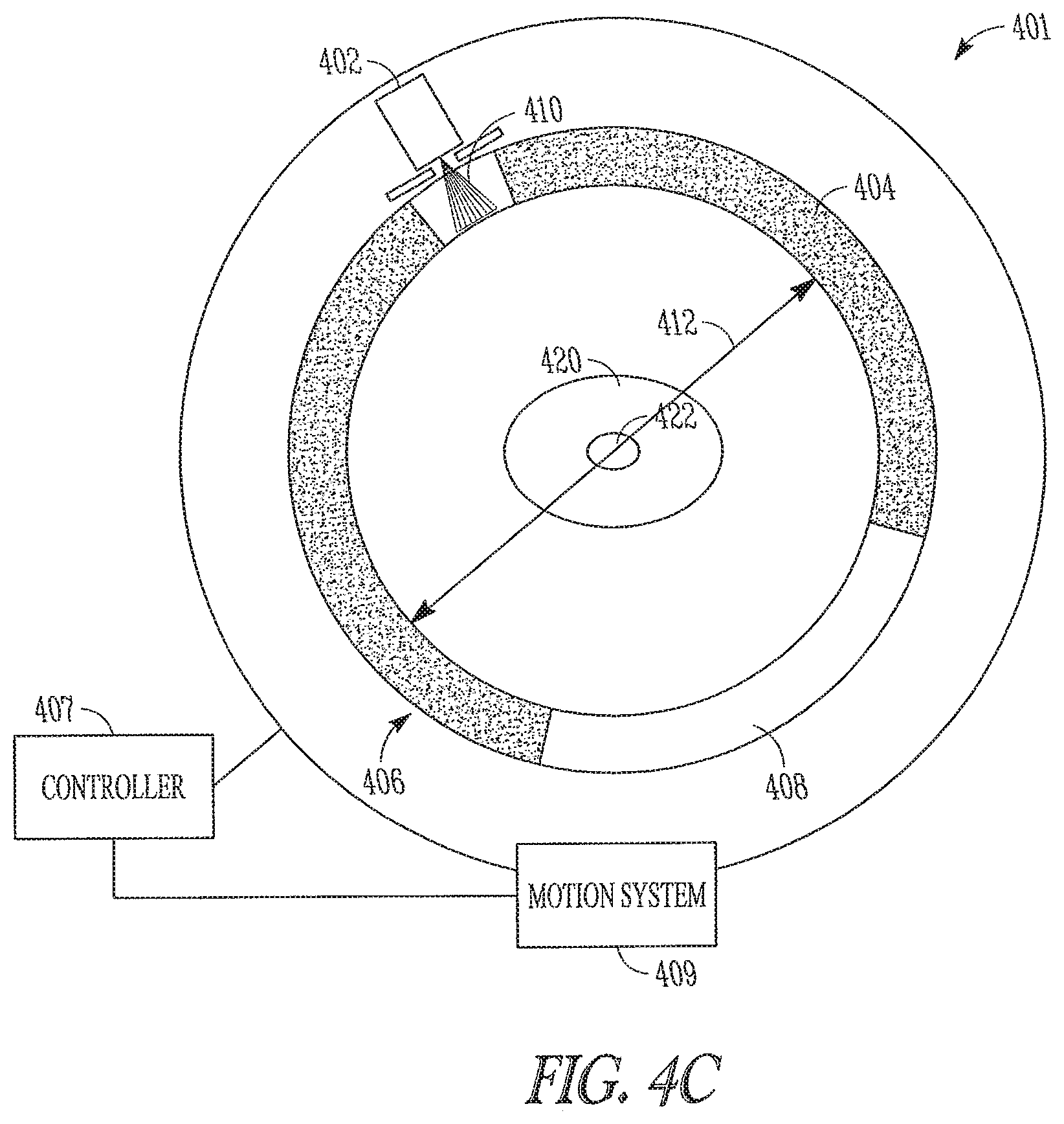
FIGS. 4A-4D show a cross section of an apparatus 401 for detecting coincident positron annihilation emissions paths and aligning radiation to the emission paths according to one embodiment of the present subject matter. FIGS. 4A-4D includes a patient 420 positioned within the apparatus 401. The patient has living tumor tissue within a volume 422 to be irradiated. The apparatus includes a controller 407, a radiation source 402 to produce high energy radiation, a collimation assembly 410 to assist shaping and precisely directing the high energy-radiation, an array of x-ray detectors 408, and an array of positron emission tomography (PET) sensors 404. The radiation source 402, collimation assembly 410, x-ray detectors 408 and PET sensors 404 are situated on a rotating gantry 406. The gantry 406 is mounted to a stationary frame (not shown). In various embodiments, a motion control system 409 connected to the controller 407 moves the gantry 406 and mounted equipment about the patient 420.
FIG. 4B shows the apparatus 401 performing a low dose, MeV CT scan to register the patient's position relative to the apparatus 401. Anatomic landmarks or other marking schemes may be used to register the patient's body position with the apparatus. Registration allows the controller to relate the geometric coordinates of the volume(s) of interest, including those volumes not to be irradiated, with the geometric coordinates of the apparatus 401. After registration, the controller 407 controls the apparatus 401 in monitoring positron annihilation emission paths intersecting the volume 422, aligning the radiation source to the emission paths and directing radiation along detected emission paths. While monitoring for positron annihilation events, the radiation source 402, collimation assembly 410, PET sensors 404 and high energy radiation detectors 408 rotate around the patient using the motion system 409 connected to the controller 407.
FIG. 4C shows detection of a coincident positron emission path 412 intersecting the volume 422. Upon detection of a coincident emission event and path 412, the controller 407, records the geometric coordinates of the coincident emission path. If the detected path 412 intersects a volume of interest 422, the controller 407 initiates alignment of the radiation source and triggers radiation along the path of the emission after the motion system has moved the radiation source 402 into alignment with the emission path 412. Applying the radiation along the same path as the emission provides a high degree of certainty that the radiation is applied precisely to living tissue of the tumor. In addition to moving the radiation source to the angle of a detected emission, alignment includes configuring the collimation assembly 410 to precisely direct the radiation along the positron emission path. In various embodiments, precise and timely alignment of the radiation includes reconfiguring the collimation assembly while the gantry 406 is rotating about the patient.
FIG. 4D shows the apparatus directing radiation along a detected emission path according to one embodiment of the present subject matter. The controller coordinates the motion of the gantry, configuration of the collimation assembly and triggering of the radiation source to provide radiation 414 from the radiation source 402 along the same path as detected positron emission paths. The collimation assembly 410 allows the radiation beam to be fragmented so that desired rays in the fan-beam may pass through while others are completely occluded. Reconfiguration of the collimation assembly occurs quickly so that a new configuration is possible for each angular position of the radiation source 402 around the gantry 406.
As the gantry 406 rotates, detection, alignment and triggering of radiation is repeated for multiple positron emission events until a desired radiation dose is achieved in each volume of interest. In various embodiments, the controller records readings received from the x-ray detectors 408 to verify the total radiation dosage. It is understood that x-ray detectors may be formed of one or more high energy detectors including, but not limited to, MeV detectors, high energy kilo-electron volt (keV) detectors or combinations thereof.
In various embodiments, the controller 407 includes data about the location of one or more tumors. In such embodiments, the controller coordinates detection of emission events and triggering and directing of radiation to the multiple volumes. In various embodiments, volume location data is downloaded into the controller from previous imaging. The data allows the controller to determine with a high degree of certainty whether a detected emission event path intersects with a volume of interest.
As discussed above, when position emission events intersecting a volume of interest are detected, the controller 407 reconfigures the collimation assembly 410 to allow radiation from the radiation source 402 to follow the same path as the detected emission path within a specified time. In various embodiments, reconfiguration of the collimation assembly is accomplished on-the-fly as the gantry 406 rotates the radiation source 402 and sensors 404, 408 about the patient 420. Speed of the gantry rotation, processing delay of the controller, and location of the radiation source upon detection of an emission event are some factors that determine the delay between the emission event and directing and triggering radiation along the emission path. In medical applications, alignment of the radiation source to emission paths increases tracking accuracy of tumors even for motion of the tumors resulting from normal body functions such as breathing. In some embodiments, the gantry includes multiple radiation sources. Multiple radiation sources allow treatment to be completed more quickly, allow delay reduction between detection of an emission event and alignment of a radiation source or both quicker treatment and reduced delay.
In various embodiments, the apparatus aligns and directs radiation in response to individual positron annihilation events. In various embodiments, the controller queues detected positron annihilation emissions as the gantry rotates, aligns and directs radiation to previously detected emission paths. In some embodiments, the radiation source is aligned and directed sequentially along selected queued paths. In some embodiments, the radiation source is aligned and directed along selected queued paths depending on the present position of the radiation source about the volume, such that a more recently detected path may be selected because the radiation source will approach that path before an earlier detected path. In some embodiments, the controller queues selected emission paths for an interval of time and then aligns and directs radiation along selected paths of the queue before repeating the process by queuing additional emission paths. By adjusting the desired time interval between sensing an event and delivering radiation along the detected emission path, the apparatus can establish a queue of different numbers of radiation delivery paths. It can also use algorithms to provide the radiation with the least amount of movement of the apparatus. Other algorithms and procedures are possible without departing from the scope of the present subject matter.
In some embodiments, the controller paces alignment and triggering of the radiation source to cyclical functions of the patient such as breathing. For example, assume the breathing cycle of a patient has been sensed to repeat every few seconds. As the controller senses emission events intersecting a volume of interest, the controller records the phases of the breathing cycle in which these events occurred and controls a coordinated delay in moving, aligning and triggering the radiation source to coincide with the same phases of the breathing cycle.
Various embodiments of the present subject mailer align and direct radiation in a 2-D or a 3-D mode. In a 2-D mode, a multi-leaf radiation collimator is reconfigured for each specified angular position of the radiation source so that radiation paths lie within a fan whose vertex is at the source of radiation. FIG. 5 shows a collimator assembly 550 according to one embodiment of the present subject matter. A pair of collimator jaws 551 immediately preceding the multi-leaf collimator 553 restricts the conical divergence 554 of the radiation source 555 to a particular plane 552. Operation of the lower jaws 553 allows alignment of the radiation to multiple volumes within the plane of the radiation path. In various embodiments, a table may be translated in a continuous fashion or in a step-and-shoot fashion to treat multiple slices of a volume. If the table is translated continuously, the table speed should allow for a prescribed dose to each volume.
In the case of an apparatus employing a 3-D mode of treatment, the collimator jaws 551 restricting the conical radiation beam divergence 554 may be moved in coordination with the collimation assembly leaves 553. Although radiation is restricted to a particular plane, coordinated motion of the collimation assembly jaws allow various planes of treatment for a given position of the radiation source. For circular gantries and C-Arm apparatus, 3-D mode allows the collimation assembly to provide radiation at angles oblique to the central axis of the apparatus. Additionally, for a given position of the apparatus, the 3-D mode allows the controller to respond to multiple coincident emission paths within a larger portion of the field of view of a PET sensor array compared to 2-D mode.
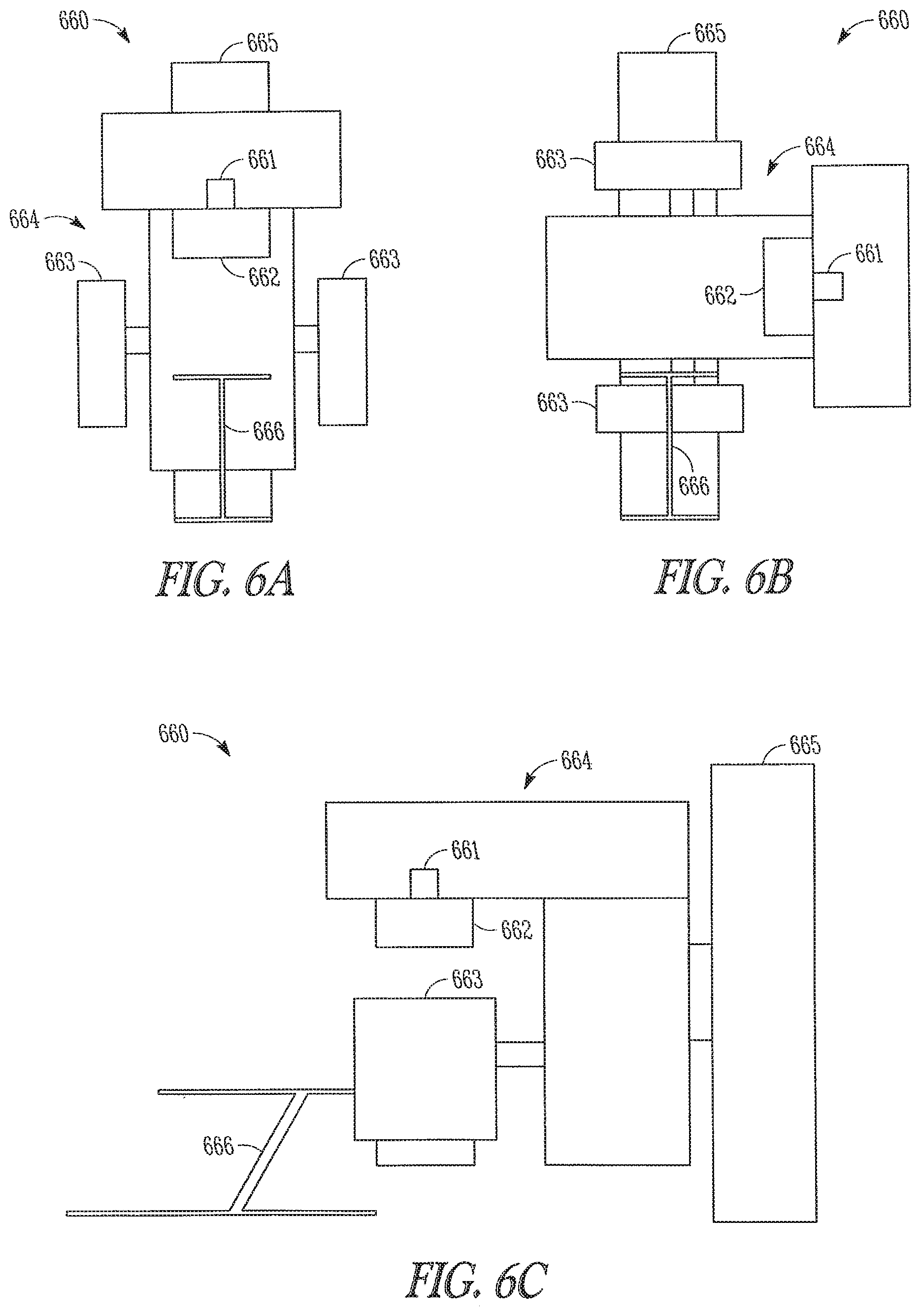
FIGS. 6A-6C shows a C-arm gantry apparatus 660 according to one embodiment of the present subject matter. The apparatus 660 includes a radiation source 661, collimation assembly 662 and PET cameras 663 mounted to a rotary section 664 of the apparatus. A fixed section 665 of the apparatus provides support for the rotary section 664. FIG. 6A shows a front view of the apparatus with the radiation source located above a table 666 and the PET cameras 663 positioned at either side of the table 666. A controller (not shown) provides control and coordination of the radiation source 661, collimation assembly 662, PET cameras 663, and motion as the rotating section 664 moves the devices about the table 666. FIG. 6B shows a front view of the apparatus with the radiation source 661, collimation assembly 662 and PET cameras 663 rotated 90 degrees about the table 666. For 3-D mode treatment, a multi-leaf x-ray collimator is reconfigured for each specified angular position of the radiation source so that the radiation paths lie within a cone whose vertex is at the source of radiation.
In various embodiments, in order to treat multiple slices of a volume, the table 666 may by translated in a continuous fashion or in a step and shoot mode. FIG. 6C shows a side view of the C-arm gantry apparatus 660 with the table 666 translated toward the apparatus. In various embodiments, where the table is translated continuously, table speed is controlled to allow for a prescribed dose of radiation to be directed to each volume.
In various embodiments, the apparatus 660 includes high energy (MeV) detectors located opposite the radiation source to record and verify the amount, or dose, of radiation directed to each volume. In some embodiments, instead of MeV detectors, combined MeV/PET detectors are used. Combined MeV/PET detectors allow detection of both 511 keV PET emissions as well as high energy radiation. Such an arrangement increases the coverage of the PET detectors and allows for a faster radiation session. It is understood that other combinations of PET and high energy x-ray detectors are possible without departing from the scope of the present subject matter including but not limited to keV/PET detectors.
In various embodiments, the radiation includes x-rays produced by a linear accelerator (linac). Other radiation types and radiation sources are possible for providing radiation without departing from the scope of the present subject matter. Such radiation and radiation sources include, but are not limited to, high energy photons, radiation or particles produced by a radioactive isotope (e.g. iridium or cobalt60), high energy electrons, a proton beam, a neutron beam and a heavy ion beam.
In one embodiment, the apparatus is implemented using a single photon emission computed tomography (SPECT) setup with pinhole cameras and/or collimated SPECT sensors in place of the PET sensors to detect the direction of emitted photons from a radioactive event.
In one embodiment, the radiation source does not rotate. Radiation sources (e.g. lead encased cobalt60) are placed all around the gantry, alternating with the PET detectors. In this case, radiation from a particular radiation source would follow the emission path detected by an adjacent PET sensor pair.
In one embodiment, two or more radiation sources are affixed to the rotating gantry. The controller aligns each of the radiation sources to respond to distinct emission paths. Multiple radiation sources permit a smaller time window between detecting an emission path and directing radiation along that path, than if only a single radiation source is used.
In various embodiment, the apparatus provides other modes of radiation therapy for stand alone operation, or for simultaneous operation with emission guided radiation therapy. Other modes of radiation therapy include, but are not limited to, radiation treatment based on prior imaging of the treatment volumes, three-dimensional conformal beam RT, intensity-modulated RT or combinations thereof.
This application is intended to cover adaptations and variations of the present subject matter. It is to be understood that the above description is intended to be illustrative, and not restrictive. The scope of the present subject matter should be determined with reference to the appended claims, along with the full scope of legal equivalents to which the claims are entitled.
* * * * *
References
D00000
D00001
D00002
D00003
D00004
D00005
D00006
D00007
D00008
XML
uspto.report is an independent third-party trademark research tool that is not affiliated, endorsed, or sponsored by the United States Patent and Trademark Office (USPTO) or any other governmental organization. The information provided by uspto.report is based on publicly available data at the time of writing and is intended for informational purposes only.
While we strive to provide accurate and up-to-date information, we do not guarantee the accuracy, completeness, reliability, or suitability of the information displayed on this site. The use of this site is at your own risk. Any reliance you place on such information is therefore strictly at your own risk.
All official trademark data, including owner information, should be verified by visiting the official USPTO website at www.uspto.gov. This site is not intended to replace professional legal advice and should not be used as a substitute for consulting with a legal professional who is knowledgeable about trademark law.