Active seat with storage
Fletcher , et al. March 30, 2
U.S. patent number 10,959,528 [Application Number 16/431,369] was granted by the patent office on 2021-03-30 for active seat with storage. This patent grant is currently assigned to The Prophet Corporation. The grantee listed for this patent is The Prophet Corporation. Invention is credited to Laura Ann Fletcher, Ryan William Rasell.


| United States Patent | 10,959,528 |
| Fletcher , et al. | March 30, 2021 |
Active seat with storage
Abstract
An active stool includes a base and a cover. The base defines an interior cavity accessible through an open end of the base. The cover removably mounts to the base to cover the open end. The cover defines a seat for a user. The base is configured to tilt along at least one rocking path. Certain types of bases are configured to tilt along multiple rocking paths.
| Inventors: | Fletcher; Laura Ann (Owatonna, MN), Rasell; Ryan William (Apple Valley, MN) | ||||||||||
|---|---|---|---|---|---|---|---|---|---|---|---|
| Applicant: |
|
||||||||||
| Assignee: | The Prophet Corporation
(Owatonna, MN) |
||||||||||
| Family ID: | 1000005451576 | ||||||||||
| Appl. No.: | 16/431,369 | ||||||||||
| Filed: | June 4, 2019 |
Prior Publication Data
| Document Identifier | Publication Date | |
|---|---|---|
| US 20200383489 A1 | Dec 10, 2020 | |
| Current U.S. Class: | 1/1 |
| Current CPC Class: | A47C 7/622 (20180801); A47C 9/02 (20130101); A47C 3/029 (20130101); A47C 13/00 (20130101); A47C 7/628 (20180801); A47C 3/16 (20130101); A47C 9/10 (20130101) |
| Current International Class: | A47C 9/00 (20060101); A47C 3/029 (20060101); A47C 9/02 (20060101); A47C 7/62 (20060101); A47C 9/10 (20060101); A47C 13/00 (20060101); A47C 3/16 (20060101) |
References Cited [Referenced By]
U.S. Patent Documents
| 2049539 | August 1936 | Greenwood |
| 2552693 | May 1951 | Smith |
| 2623633 | December 1952 | Bladow |
| 2742953 | April 1956 | Kudrna |
| D198679 | July 1964 | Cartner |
| 3312437 | April 1967 | Barth |
| 3563605 | February 1971 | Pinkas |
| 3604749 | September 1971 | Parmett et al. |
| D228095 | August 1973 | Schmitt |
| 3751845 | August 1973 | van Leeuwen |
| D232499 | August 1974 | Martinelli |
| D232504 | August 1974 | Archinal |
| D234933 | April 1975 | Burke |
| 4084273 | April 1978 | Haynes |
| 4232901 | November 1980 | Harrington |
| 4845881 | July 1989 | Ward |
| 5112103 | May 1992 | Downer |
| 5226865 | July 1993 | Chin |
| D498067 | November 2004 | Van Dyke |
| 7341314 | March 2008 | Boyd |
| D586574 | February 2009 | Gomree |
| D625931 | October 2010 | Estrup |
| D647313 | October 2011 | Chen |
| D650184 | December 2011 | Hsu |
| D671757 | December 2012 | Walker et al. |
| 8764116 | July 2014 | Weber |
| 9010867 | April 2015 | Martin |
| D728951 | May 2015 | Yoshida |
| 9078526 | July 2015 | Kammeyer |
| 9138058 | September 2015 | Koolhaas |
| 9167899 | October 2015 | Jackson |
| D767290 | September 2016 | Walser |
| 9567135 | February 2017 | Spadaccini |
| D791523 | July 2017 | Bernard |
| D809309 | February 2018 | Theesfeld |
| D809310 | February 2018 | Mathur et al. |
| D809809 | February 2018 | Theesfeld et al. |
| D812919 | March 2018 | Kim |
| 9974391 | May 2018 | Wan |
| D830710 | October 2018 | Harguth et al. |
| 10258160 | April 2019 | Risdall |
| 10390629 | August 2019 | Phillips |
| 10517399 | December 2019 | Harguth |
| 2008/0265631 | October 2008 | Quicoy |
| 2010/0066139 | March 2010 | Woodring |
| 2010/0244501 | September 2010 | Chiang |
| 2019/0098998 | April 2019 | Harguth et al. |
| 2020/0022499 | January 2020 | Davidson |
| 8-112155 | May 1995 | JP | |||
Other References
|
Plastic Round Stools, Retrieved May 2, 2018 from URL: <http://www.umaplastics.com/plastic-round-stools.html>, 5 pages. cited by applicant . Play with a Purpose Catalog; Spring 2017; .COPYRGT. 2017 Gopher Sport; 4 pages. cited by applicant . Thick plastic small round stools, home adult children bathroom stool, changing his shoes stool, Retrieved May 2, 2018 from URL: <https://www.aliexpress.com/item/Thick-plastic-small-round-stools-home- -adult-children-bathroom-stool-changing-his-shoes-stool/32507580751.html, 17 pages. cited by applicant . TiltED Active Seats, Retrieved May 2, 2018 from URL: https://www.gophersport.com/pe/active-classroom/tilted-active-seats?item =25259&pt_source=googleads&pt_med i um =cpc&pt_campaign=Shopping_-_%E2%80%A6, 2 pages. cited by applicant. |
Primary Examiner: Islam; Syed A
Attorney, Agent or Firm: Merchant & Gould P.C.
Claims
What is claimed is:
1. An active stool comprising: a base defining an interior cavity accessible through an open end of the base, the interior cavity extending along a majority of a height of the base, the base being configured to tilt along at least one rocking path; and a cover removably mountable to the base to cover the open end, the cover defining a seat facing away from the interior cavity when the cover is mounted to the base.
2. The active stool of claim 1, wherein the seat is formed by a depression defined in the cover.
3. The active stool of claim 2, wherein the depression is concave.
4. The active stool of claim 1, wherein the seat extends over a majority of a cross-sectional area of the cover.
5. The active stool of claim 1, wherein the cover includes handles.
6. The active stool of claim 5, wherein the handles are recessed into sides of the cover.
7. The active stool of claim 1, wherein a cross-sectional area of the interior cavity extends over a majority of a cross-sectional area of the base.
8. The active stool of claim 1, wherein the base defines a spherical cap opposite the open end.
9. The active stool of claim 1, wherein the base is configured to tilt along a plurality of rotationally offset rocking paths.
10. The active stool of claim 1, wherein the interior cavity of the base is partially bounded by a pair of opposing flat sides.
11. A storage device comprising: a base extending between a first end and a second end, the first end defining a convex surface, the base defining an interior cavity accessible through an aperture at the second end, the interior cavity having a cross-sectional area that extends over a majority of a cross-sectional area of the base; and a cover removably mountable to the base at the second end to cover the aperture.
12. The storage device of claim 11, wherein the base has a height extending between the first and second ends, and wherein the interior cavity extends along a majority of the height of the base.
13. The storage device of claim 11, wherein a cross-sectional area of the interior cavity has a common shape with a cross-sectional area of the base.
14. The storage device of claim 13, wherein the convex surface has a circular cross-dimension.
15. The storage device of claim 13, wherein the convex surface is shaped as a spherical cap.
16. The storage device of claim 11, wherein the base has a square cross-sectional area.
17. The storage device of claim 16, wherein the cover has a square cross-sectional area.
18. The storage device of claim 11, wherein the base has an oblong cross-sectional area.
19. The storage device of claim 18, wherein the cover has an oblong cross-sectional area.
Description
BACKGROUND
Active seating allows a user freedom of movement while remaining seated. For example, a user may be able to pivot, rotate, or otherwise move the seat while sitting in the seat. Other seating includes pedals or other structures that can be moved by the user while the user remains seated. Improvements are desired.
SUMMARY
Some aspects of the disclosure are directed to an active stool providing storage for items. For example, such an active stool could be used in a classroom setting. A child can sit on the active stool during lessons and store items (e.g., books, backpack, writing implements, paper, art supplies, gym clothes, or any desired items) within a cavity defined by the active stool.
The active stool includes a base and a cover. The base has a tilting surface that defines at least one rocking path along which the base can tilt. The base also defines a cavity accessible through an open end. The cover is mountable to the base to close the open end. The cover defines a seat on which the user sits when using the active stool.
In certain implementations, the base is configured to tilt along a plurality of rotationally offset rocking paths. In certain examples, the base defines a spherical cap opposite the open end.
In certain implementations, the seat is formed by a depression defined in the cover. In certain implementations, the seat extends over a majority of a cross-sectional area of the cover.
In certain implementations, the cover includes handles. In some examples, the handles are integral with the cover. In other examples, the handles are separate pieces mounted to the cover.
In certain implementations, the interior cavity extends along a majority of a height of the base. In certain implementations, a cross-sectional area of the interior cavity extends over a majority of a cross-sectional area of the base.
A variety of additional inventive aspects will be set forth in the description that follows. The inventive aspects can relate to individual features and to combinations of features. It is to be understood that both the forgoing general description and the following detailed description are exemplary and explanatory only and are not restrictive of the broad inventive concepts upon which the embodiments disclosed herein are based.
BRIEF DESCRIPTION OF THE DRAWINGS
The accompanying drawings, which are incorporated in and constitute a part of the description, illustrate several aspects of the present disclosure. A brief description of the drawings is as follows:
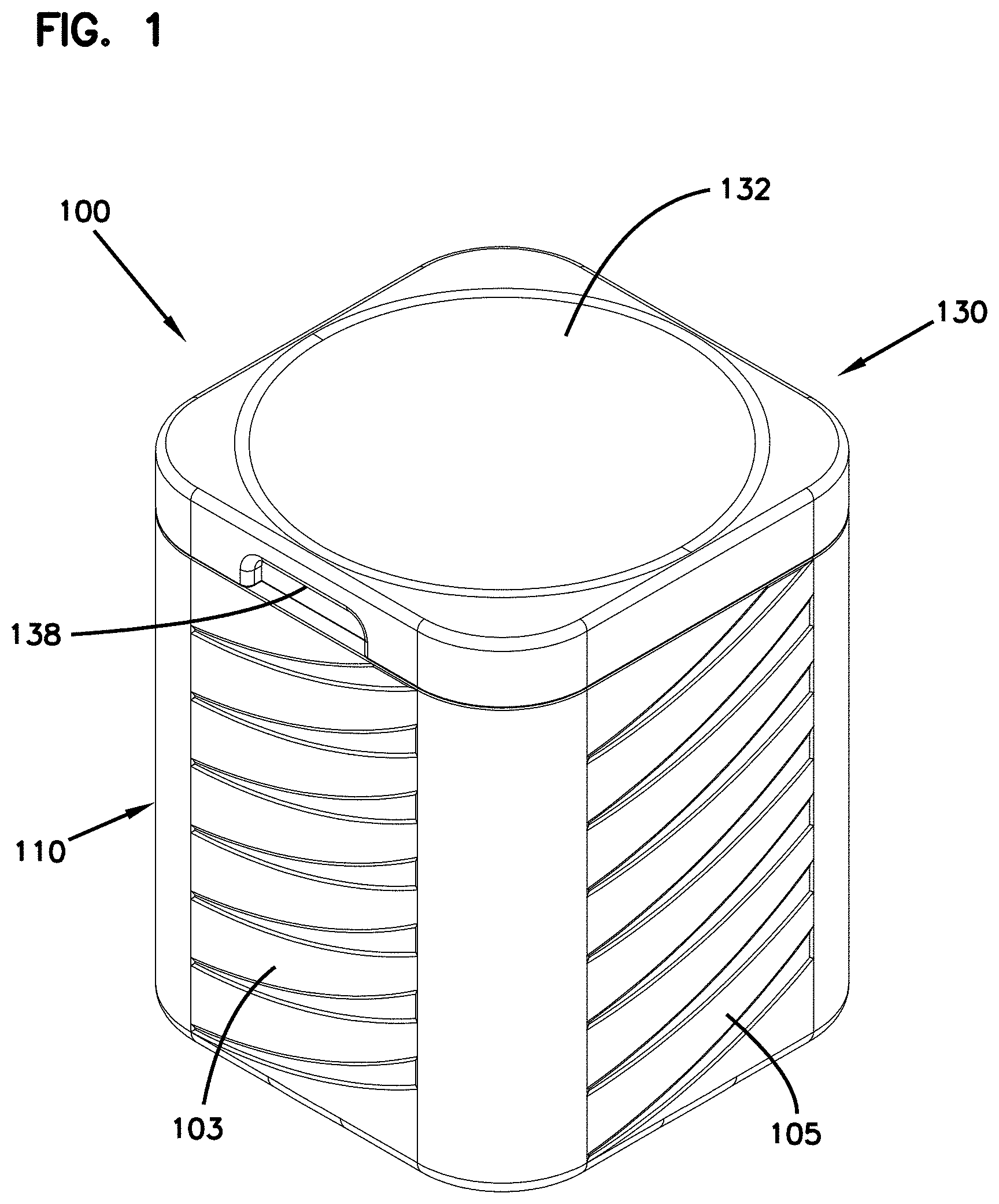
FIG. 1 is a top perspective view of an example active stool configured in accordance with the principles of the present disclosure, the active stool including a cover and a base;
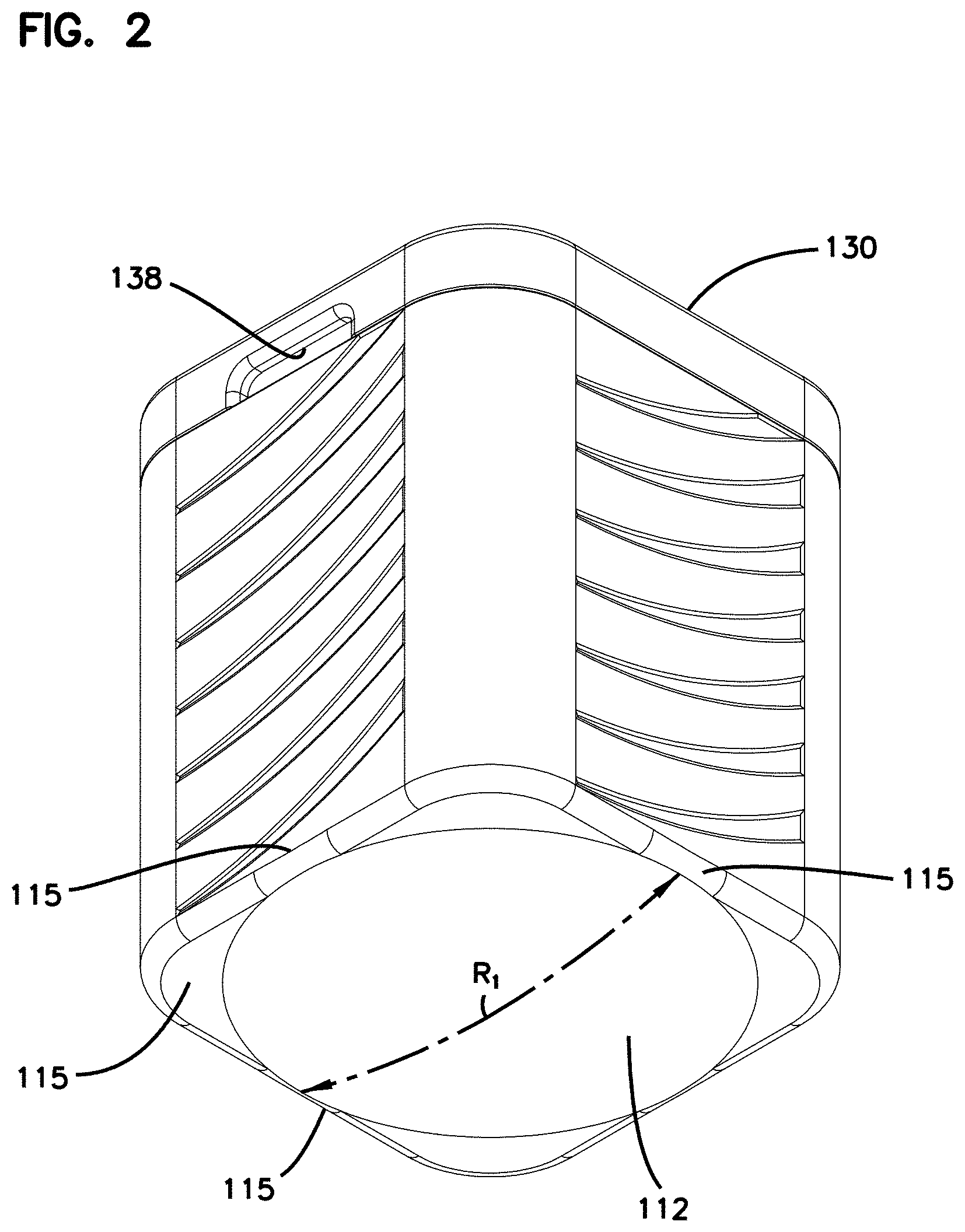
FIG. 2 is a bottom perspective view of the active stool of FIG. 1;
FIG. 3 is a bottom plan view of the active stool of FIG. 1;
FIG. 4 is a first side elevational view of the active stool of FIG. 1 tilted along a first rocking path in a first direction;
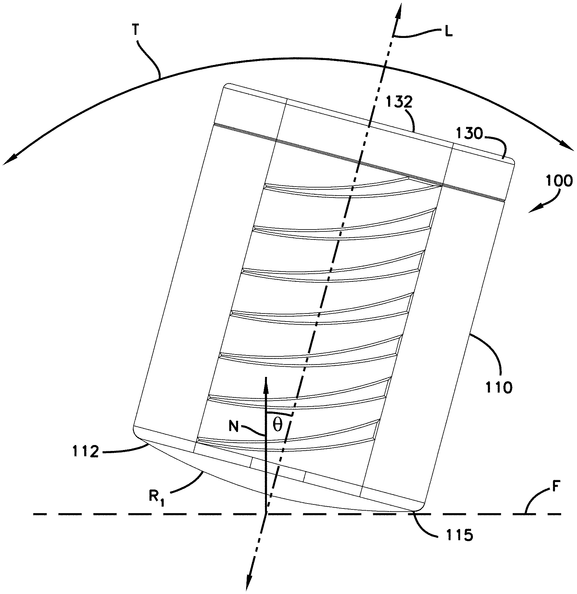
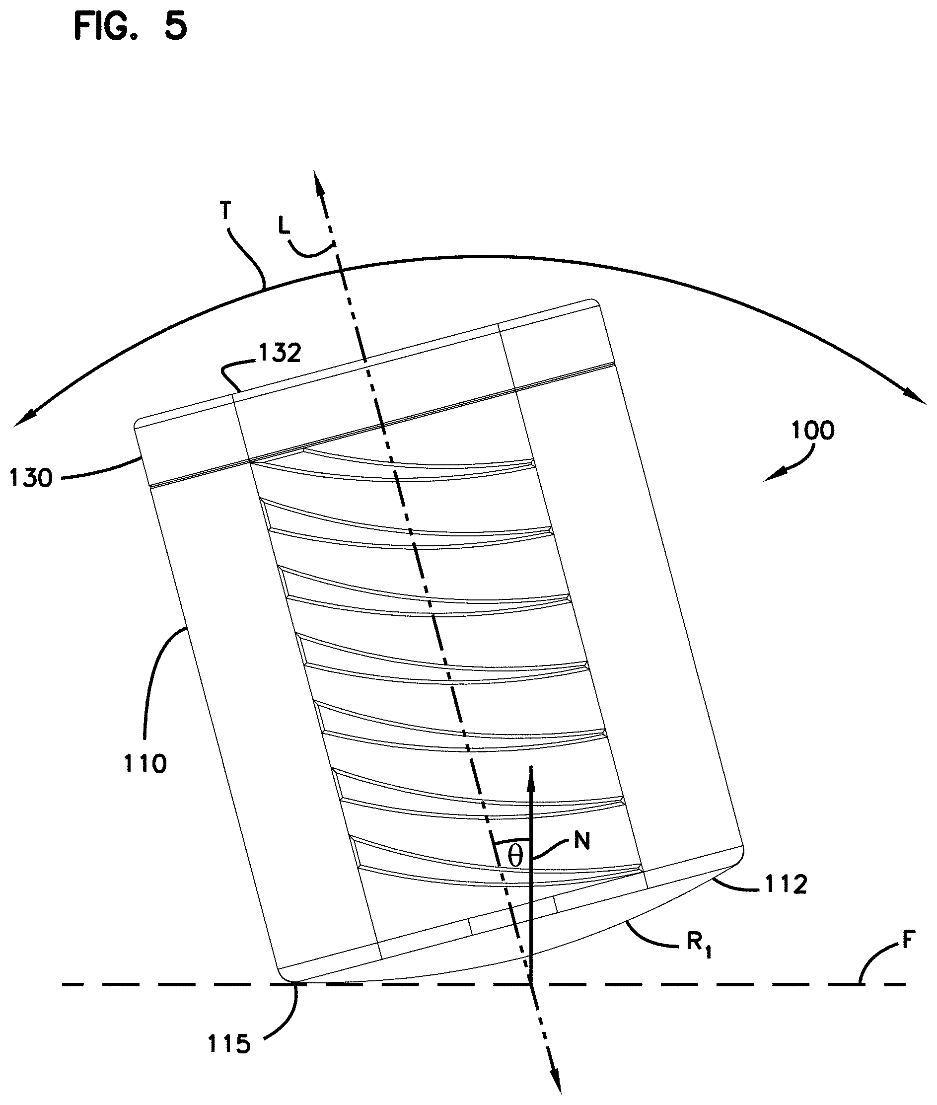
FIG. 5 is a first side elevational view of the active stool of FIG. 1 tilted along the first rocking path in a second direction;
FIG. 6 is a perspective view of the active stool of FIG. 1 with the top exploded away from the base;
FIG. 7 is a cross-sectional view of the base of the active stool of FIG. 1 with the cover removed; and
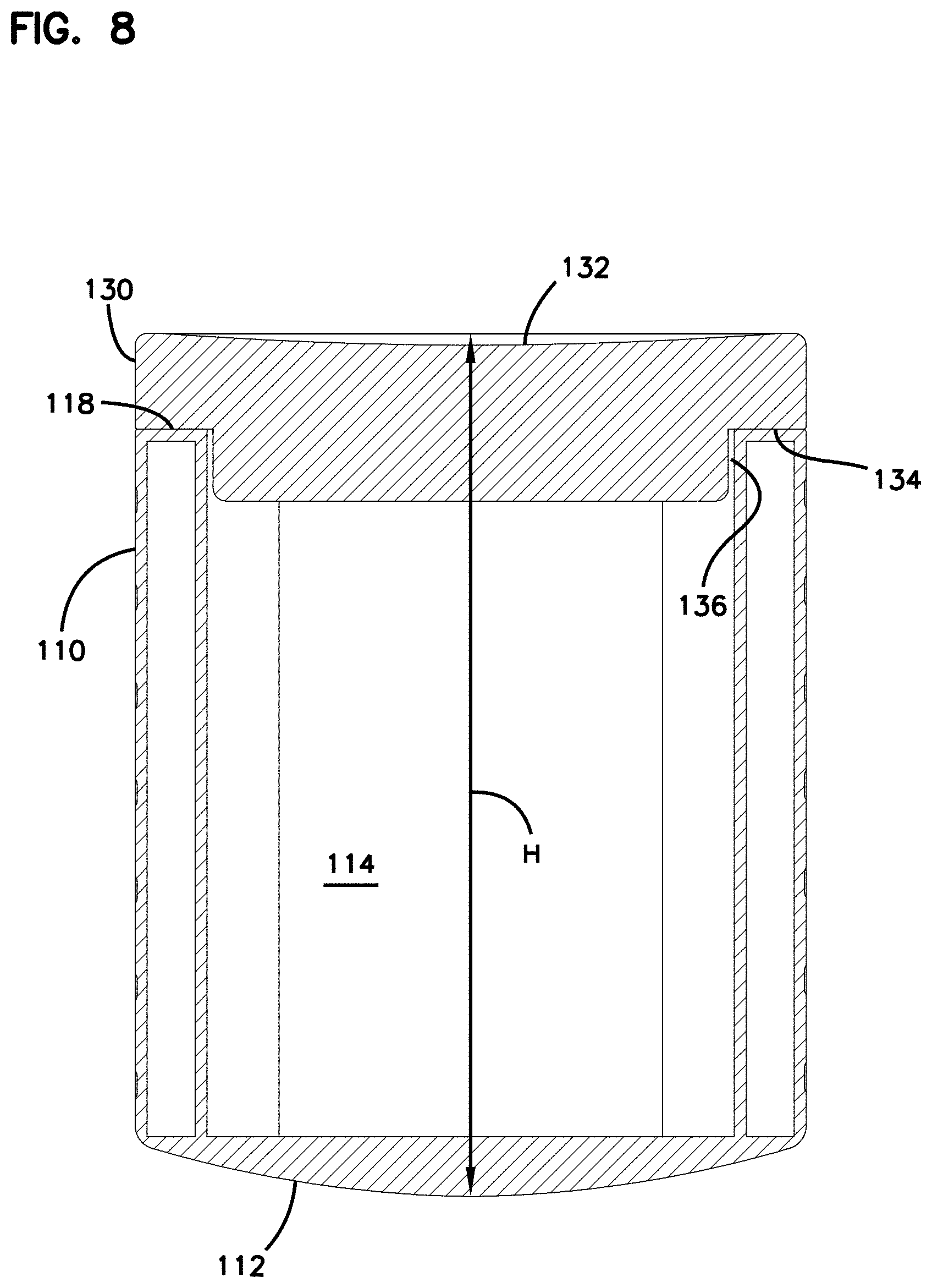
FIG. 8 is a cross-sectional view of the active stool of FIG. 1.
DETAILED DESCRIPTION
Reference will now be made in detail to exemplary aspects of the present disclosure that are illustrated in the accompanying drawings. Wherever possible, the same reference numbers will be used throughout the drawings to refer to the same or like parts.
The present disclosure is directed to an active stool providing storage for items.
Referring to FIGS. 1 and 2, an example active stool 100 includes a seat 132 on which a user can sit when utilizing the stool 100. The active stool 100 also includes a convex surface 112 facing in an opposite direction from the seat 132. The convex surface 112 defines at least a first rocking path R1 along which the stool 100 can tilt. The convex surface 112 allows a user to rock on the stool 100 along at least the first rocking path R1.
The active stool 100 extends along a height H (FIG. 8) between the convex surface 112 and the top of the cover 130, along a width W (FIG. 3) between opposite sides 103, 104, and along a depth D (FIG. 3) between opposite ends 105, 106. In certain examples, the height H is greater than the width W and greater than the depth D. In certain examples, the width W is about equal to the depth D. The stool 100 has a central longitudinal axis L (FIGS. 4 and 5) extending along the height H of the stool 100.
In certain implementations, the active stool 100 has a generally rectangular outer transverse cross-sectional shape. In certain implementations, the active stool 100 has a generally square outer transverse cross-sectional shape. In certain implementations, the active stool 100 has a generally oblong outer transverse cross-sectional shape. In certain implementations, the active stool 100 has a generally circular outer transverse cross-sectional shape. In certain examples, the convex surface 112 fits within a footprint formed by the outer transverse cross-sectional shape of the active stool 100 (e.g., see FIG. 3).
As shown in FIG. 3, in certain examples, the convex surface 112 defines a plurality of rocking paths (e.g., see rocking paths R1, R2, and R3) along which the stool 100 can be tilted. For simplicity, three example rocking paths R1, R2, R3 are illustrated. It will be understood by a person skilled in the art that the convex surface 112 provides additional rocking paths. In certain examples, the rocking paths are rotationally offset from each other (e.g., compare rocking paths R1 and R2), thereby allowing a user to rock along different directions (e.g., forward-rearward, side-to-side, etc.). In certain examples, the rocking paths are laterally offset from each other (e.g., compare rocking paths R1 and R3), thereby allowing a user to rock in the same direction at different tilt angles. In an example, the convex surface 112 defines a spherical cap. Accordingly, the convex surface 112 has an infinite number of rocking paths. In other examples, the convex surface 112 may have other contoured shapes.
In certain examples, stop portions of the stool 100 extend laterally outwardly beyond the convex surface 112. In the example shown in FIG. 5, the stop portions surround the convex surface 112. The rocking paths R1, R2, R3 end at the stop portions 115. Accordingly, the stop portions 115 inhibit further tilting of the stool 100 along the rocking paths R1, R2, R3.
As shown in FIGS. 4 and 5, as the stool 100 tilts along the rocking path R1, there is a change in angle .theta. between the longitudinal axis L of the stool 100 and a reference axis N normal to a floor F on which the stool 100 is disposed. In certain implementations, the convex surface 112 allows the stool 100 to tilt up to an angle .theta. of 45 degrees in either direction along the rocking path R1. In certain implementations, the convex surface 112 allows the stool 100 to tilt up to an angle .theta. of 40 degrees in either direction along the rocking path R1. In certain implementations, the convex surface 112 allows the stool 100 to tilt up to an angle .theta. of 35 degrees in either direction along the rocking path R1. In certain implementations, the convex surface 112 allows the stool 100 to tilt up to an angle .theta. of 30 degrees in either direction along the rocking path R1. In certain implementations, the convex surface 112 allows the stool 100 to tilt at an angle .theta. of between about 5 degrees and about 45 degrees in either direction along the rocking path R1. In certain implementations, the convex surface 112 allows the stool 100 to tilt at an angle .theta. of between about 10 degrees and about 35 degrees in either direction along the rocking path R1. In certain implementations, the convex surface 112 allows the stool 100 to tilt at an angle .theta. of between about 15 degrees and about 25 degrees in either direction along the rocking path R1.
As shown in FIG. 6, the active stool 100 includes a base 110 and a cover 130. The cover 130 defines the seat 132. In some implementations, the base 110 defines the convex surface 112. In other implementations, the convex surface 112 is a separate piece that attaches to the base 110. In certain examples, a gasket or other liner is disposed between the base 110 and the cover 130.
As shown in FIGS. 6-8, the base 110 defines a cavity 114 accessible through an open end 116 of the base 110. In certain implementations, the open end 116 of the base 110 is located opposite the convex surface 112. In certain implementations, a rim 118 surrounds the open end 116 of the cavity 114. When the cover 130 is mounted to the base 110, the cover 130 rests on the rim 118 as will be described in more detail herein.
In certain implementations, the cavity 114 extends within a majority of the base 110. In certain examples, a cross-sectional area of the cavity 114 has a common shape with a cross-sectional area of the base 110. In certain examples, a cross-sectional area of the cavity 114 extends over a majority of a cross-sectional area of the base 110. In certain examples, the cavity 114 has a height H2 that extends along a majority of a height H1 of the base 110 (see FIG. 7). In certain examples, the cavity 114 has a width W2 that extends along a majority of a width W1 of the base 110 (see FIG. 7). In certain examples, the cavity 114 has a depth that extends along a majority of a depth of the base 110. In certain examples, the width and the depth of the cavity 114 are the same. In certain examples, the height H2 of the cavity 114 is greater than the width W2 and greater than the depth.
In certain examples, the width W2 of the cavity 114 is between about eight inches and twenty-four inches. In certain examples, the width W2 of the cavity 114 is between about nine inches and twenty inches. In certain examples, the width W2 of the cavity 114 is between about ten inches and eighteen inches. In certain examples, the width W2 of the cavity 114 is between about eleven inches and sixteen inches. In certain examples, the width W2 of the cavity 114 is about eleven inches. In certain examples, the width W2 of the cavity 114 is about twelve inches.
In certain examples, the height H2 of the cavity 114 is at least twelve inches. In certain examples, the height H2 of the cavity 114 is at least fourteen inches. In certain examples, the height H2 of the cavity 114 is at least sixteen inches. In certain examples, the height H2 of the cavity 114 is at least seventeen inches. In certain examples, the height H2 of the cavity 114 is about eighteen inches. In certain examples, the height H2 of the cavity 114 is about twenty inches. In certain examples, the height H2 of the cavity 114 is between about twelve inches and about thirty-six inches. In certain examples, the height H2 of the cavity 114 is between about fourteen inches and about thirty inches. In certain examples, the height H2 of the cavity 114 is between about sixteen inches and about twenty-four inches.
As shown in FIGS. 6 and 8, the cover 130 is configured to mount to the base 110 to close the open end 116 of the base 110. The cover 130 includes a cap 134 that is sized to extend over the rim 116 of the base 110. In certain examples, a bottom protrusion 136 extends downwardly from the cap 134. The bottom protrusion 136 is sized to fit within the cavity 114 of the base 110 (see FIG. 8). In certain examples, the bottom protrusion 136 is sized to fit snugly with the cavity 114 to inhibit lateral movement of the cover 130 relative to the base 110.
In certain examples, the cover 130 includes one or more handles 138 to facilitate removing the cover 130 from the base 110 and positioning the cover 130 at the base 110. In some examples, the handles 138 are recessed into the cap 134 (e.g., see FIG. 6). In other examples, the handles 138 protrude from the cap 134. In some examples, the handles 138 are integral with the cover 130. In other examples, the handles are separate pieces (e.g., straps, pulls, knobs, etc.) attached to the cover 130.
The cover 130 defines the seat 132 for the user. The seat 132 faces away from the cavity 114 when the cover 130 is mounted to the base 110. In the example shown, the seat 132 is defined by a depression within the cap 134 (e.g., see FIG. 8). In other examples, the seat 132 may be planar with the cap 134 or may even protrude from the cap 134. In certain examples, the seat 132 is symmetrical so that a user may sit on the seat 132 in any desired rotational orientation (i.e., facing any of 360 degrees around the longitudinal axis L of the stool 100). In the example shown, the seat 132 is formed by a concave depression in the cap 134. In certain implementations, the seat 132 extends over a majority of a cross-sectional area of the cover 130.
Having described the preferred aspects and implementations of the present disclosure, modifications and equivalents of the disclosed concepts may readily occur to one skilled in the art. However, it is intended that such modifications and equivalents be included within the scope of the claims which are appended hereto.
* * * * *
References
-
umaplastics.com/plastic-round-stools.html
-
aliexpress.com/item/Thick-plastic-small-round-stools-home-adult-children-bathroom-stool-changing-his-shoes-stool/32507580751.html
-
gophersport.com/pe/active-classroom/tilted-active-seats?item=25259&pt_source=googleads&pt_medium=cpc&pt_campaign=Shopping_-_%E2%80%A6
D00000
D00001
D00002
D00003
D00004
D00005
D00006
D00007
D00008
XML
uspto.report is an independent third-party trademark research tool that is not affiliated, endorsed, or sponsored by the United States Patent and Trademark Office (USPTO) or any other governmental organization. The information provided by uspto.report is based on publicly available data at the time of writing and is intended for informational purposes only.
While we strive to provide accurate and up-to-date information, we do not guarantee the accuracy, completeness, reliability, or suitability of the information displayed on this site. The use of this site is at your own risk. Any reliance you place on such information is therefore strictly at your own risk.
All official trademark data, including owner information, should be verified by visiting the official USPTO website at www.uspto.gov. This site is not intended to replace professional legal advice and should not be used as a substitute for consulting with a legal professional who is knowledgeable about trademark law.