Compressor having capacity modulation assembly
Akei , et al. March 23, 2
U.S. patent number 10,954,940 [Application Number 15/881,016] was granted by the patent office on 2021-03-23 for compressor having capacity modulation assembly. This patent grant is currently assigned to Emerson Climate Technologies, Inc.. The grantee listed for this patent is Emerson Climate Technologies, Inc.. Invention is credited to Masao Akei, Roy J. Doepker.


View All Diagrams
| United States Patent | 10,954,940 |
| Akei , et al. | March 23, 2021 |
Compressor having capacity modulation assembly
Abstract
A compressor may include a shell, first and second scrolls, a seal assembly, a modulation control chamber, and a modulation control valve. The first scroll may include a first end plate having a biasing passage extending therethrough. The seal assembly may isolate a discharge pressure region from a suction pressure region. The seal assembly and the first scroll may define an axial biasing chamber therebetween that communicates with the axial biasing chamber and a first pocket between the first and second scrolls. The modulation control chamber may be fluidly coupled with the biasing chamber by a first passage. The modulation control valve may be fluidly coupled with the modulation control chamber by a second passage and movable between a first position allowing communication between the second passage and the suction pressure region and a second position restricting communication between the second passage and the suction pressure region.
| Inventors: | Akei; Masao (Cicero, NY), Doepker; Roy J. (Lima, OH) | ||||||||||
|---|---|---|---|---|---|---|---|---|---|---|---|
| Applicant: |
|
||||||||||
| Assignee: | Emerson Climate Technologies,
Inc. (Sidney, OH) |
||||||||||
| Family ID: | 1000005439012 | ||||||||||
| Appl. No.: | 15/881,016 | ||||||||||
| Filed: | January 26, 2018 |
Prior Publication Data
| Document Identifier | Publication Date | |
|---|---|---|
| US 20180149155 A1 | May 31, 2018 | |
Related U.S. Patent Documents
| Application Number | Filing Date | Patent Number | Issue Date | ||
|---|---|---|---|---|---|
| 14946824 | Nov 20, 2015 | 9879674 | |||
| 14081390 | Apr 5, 2016 | 9303642 | |||
| 13181065 | Nov 19, 2013 | 8585382 | |||
| 12754920 | Aug 2, 2011 | 7988433 | |||
| 61167309 | Apr 7, 2009 | ||||
| Current U.S. Class: | 1/1 |
| Current CPC Class: | F04C 28/265 (20130101); F04C 18/0215 (20130101); F04C 18/0253 (20130101); F04C 29/12 (20130101); F04C 23/008 (20130101); F04C 28/18 (20130101); F01C 1/0215 (20130101); F04C 18/0261 (20130101); F04C 27/005 (20130101); F04C 29/0021 (20130101); F01C 1/0253 (20130101); F01C 2021/165 (20130101); F04C 2270/58 (20130101); F01C 2021/1643 (20130101) |
| Current International Class: | F03C 4/00 (20060101); F04C 23/00 (20060101); F04C 29/12 (20060101); F04C 28/18 (20060101); F04C 2/00 (20060101); F04C 18/00 (20060101); F04C 18/02 (20060101); F01C 1/02 (20060101); F04C 27/00 (20060101); F04C 28/26 (20060101); F04C 29/00 (20060101); F01C 21/00 (20060101) |
| Field of Search: | ;418/15,55.1-55.6,57,104,180,270 ;417/229,307,308,310,440 |
References Cited [Referenced By]
U.S. Patent Documents
| 4058988 | November 1977 | Shaw |
| 4216661 | August 1980 | Tojo et al. |
| 4382370 | May 1983 | Suefuji et al. |
| 4383805 | May 1983 | Teegarden et al. |
| 4389171 | June 1983 | Eber et al. |
| 4466784 | August 1984 | Hiraga |
| 4475360 | October 1984 | Suefuji et al. |
| 4475875 | October 1984 | Sugimoto et al. |
| 4496296 | January 1985 | Arai et al. |
| 4497615 | February 1985 | Griffith |
| 4545742 | October 1985 | Schaefer |
| 4547138 | October 1985 | Mabe et al. |
| 4552518 | November 1985 | Utter |
| 4564339 | January 1986 | Nakamura et al. |
| 4580949 | April 1986 | Maruyama et al. |
| 4609329 | September 1986 | Pillis et al. |
| 4650405 | March 1987 | Iwanami et al. |
| 4696630 | September 1987 | Sakata et al. |
| 4727725 | March 1988 | Nagata et al. |
| 4772188 | September 1988 | Kimura et al. |
| 4774816 | October 1988 | Uchikawa et al. |
| 4818195 | April 1989 | Murayama et al. |
| 4824344 | April 1989 | Kimura et al. |
| 4838773 | June 1989 | Noboru |
| 4842499 | June 1989 | Nishida et al. |
| 4846633 | July 1989 | Suzuki et al. |
| 4877382 | October 1989 | Caillat et al. |
| 4886425 | December 1989 | Itahana et al. |
| 4886433 | December 1989 | Maier |
| 4898520 | February 1990 | Nieter et al. |
| 4927339 | May 1990 | Riffe et al. |
| 4940395 | July 1990 | Yamamoto et al. |
| 4954057 | September 1990 | Caillat et al. |
| 4990071 | February 1991 | Sugimoto |
| 4997349 | March 1991 | Richardson, Jr. |
| 5024589 | June 1991 | Jetzer et al. |
| 5040952 | August 1991 | Inoue et al. |
| 5040958 | August 1991 | Arata et al. |
| 5055010 | October 1991 | Logan |
| 5059098 | October 1991 | Suzuki et al. |
| 5071323 | December 1991 | Sakashita et al. |
| 5074760 | December 1991 | Hirooka et al. |
| 5080056 | January 1992 | Kramer et al. |
| 5085565 | February 1992 | Barito |
| 5098265 | March 1992 | Machida et al. |
| 5145346 | September 1992 | Iio et al. |
| 5152682 | October 1992 | Morozumi et al. |
| RE34148 | December 1992 | Terauchi et al. |
| 5169294 | December 1992 | Barito |
| 5171141 | December 1992 | Morozumi et al. |
| 5192195 | March 1993 | Iio et al. |
| 5193987 | March 1993 | Iio et al. |
| 5199862 | April 1993 | Kondo et al. |
| 5213489 | May 1993 | Kawahara et al. |
| 5240389 | August 1993 | Oikawa et al. |
| 5253489 | October 1993 | Yoshii |
| 5304047 | April 1994 | Shibamoto |
| 5318424 | June 1994 | Bush et al. |
| 5330463 | July 1994 | Hirano |
| 5336068 | August 1994 | Sekiya et al. |
| 5340287 | August 1994 | Kawahara et al. |
| 5356271 | October 1994 | Miura et al. |
| 5395224 | March 1995 | Caillat et al. |
| 5411384 | May 1995 | Bass et al. |
| 5425626 | June 1995 | Tojo et al. |
| 5427512 | June 1995 | Kohsokabe et al. |
| 5451146 | September 1995 | Inagaki et al. |
| 5458471 | October 1995 | Ni |
| 5458472 | October 1995 | Kobayashi et al. |
| 5482637 | January 1996 | Rao et al. |
| 5511959 | April 1996 | Tojo et al. |
| 5547354 | August 1996 | Shimizu et al. |
| 5551846 | September 1996 | Taylor et al. |
| 5557897 | September 1996 | Kranz et al. |
| 5562426 | October 1996 | Watanabe et al. |
| 5577897 | November 1996 | Inagaki et al. |
| 5591014 | January 1997 | Wallis et al. |
| 5607288 | March 1997 | Wallis et al. |
| 5611674 | March 1997 | Bass et al. |
| 5613841 | March 1997 | Bass et al. |
| 5624247 | April 1997 | Nakamura |
| 5639225 | June 1997 | Matsuda et al. |
| 5640854 | June 1997 | Fogt et al. |
| 5649817 | July 1997 | Yamazaki |
| 5660539 | August 1997 | Matsunaga et al. |
| 5674058 | October 1997 | Matsuda et al. |
| 5678985 | October 1997 | Brooke et al. |
| 5707210 | January 1998 | Ramsey et al. |
| 5722257 | March 1998 | Ishii et al. |
| 5741120 | April 1998 | Bass et al. |
| 5775893 | July 1998 | Takao et al. |
| 5842843 | December 1998 | Haga |
| 5855475 | January 1999 | Fujio et al. |
| 5885063 | March 1999 | Makino et al. |
| 5888057 | March 1999 | Kitano et al. |
| 5938417 | August 1999 | Takao et al. |
| 5993171 | November 1999 | Higashiyama |
| 5993177 | November 1999 | Terauchi et al. |
| 6030192 | February 2000 | Hill et al. |
| 6047557 | April 2000 | Pham et al. |
| 6068459 | May 2000 | Clarke et al. |
| 6086335 | July 2000 | Bass et al. |
| 6093005 | July 2000 | Nakamura |
| 6095765 | August 2000 | Khalifa |
| 6102671 | August 2000 | Yamamoto et al. |
| 6123517 | September 2000 | Brooke et al. |
| 6123528 | September 2000 | Sun et al. |
| 6132179 | October 2000 | Higashiyama |
| 6139287 | October 2000 | Kuroiwa et al. |
| 6139291 | October 2000 | Perevozchikov |
| 6149401 | November 2000 | Iwanami et al. |
| 6152714 | November 2000 | Mitsuya et al. |
| 6164940 | December 2000 | Terauchi et al. |
| 6174149 | January 2001 | Bush |
| 6176686 | January 2001 | Wallis et al. |
| 6179589 | January 2001 | Bass et al. |
| 6202438 | March 2001 | Barito |
| 6210120 | April 2001 | Hugenroth et al. |
| 6213731 | April 2001 | Doepker et al. |
| 6231316 | May 2001 | Wakisaka et al. |
| 6257840 | July 2001 | Ignatiev et al. |
| 6264444 | July 2001 | Nakane et al. |
| 6267565 | July 2001 | Seibel et al. |
| 6273691 | August 2001 | Morimoto et al. |
| 6280154 | August 2001 | Clendenin et al. |
| 6290477 | September 2001 | Gigon |
| 6293767 | September 2001 | Bass |
| 6293776 | September 2001 | Hahn et al. |
| 6309194 | October 2001 | Fraser et al. |
| 6322340 | November 2001 | Itoh et al. |
| 6338912 | January 2002 | Ban et al. |
| 6350111 | February 2002 | Perevozchikov et al. |
| 6361890 | March 2002 | Ban et al. |
| 6379123 | April 2002 | Makino et al. |
| 6389837 | May 2002 | Morozumi |
| 6412293 | July 2002 | Pham et al. |
| 6413058 | July 2002 | Williams et al. |
| 6419457 | July 2002 | Seibel et al. |
| 6428286 | August 2002 | Shimizu et al. |
| 6454551 | September 2002 | Kuroki et al. |
| 6457948 | October 2002 | Pham |
| 6464481 | October 2002 | Tsubai et al. |
| 6478550 | November 2002 | Matsuba et al. |
| 6506036 | January 2003 | Tsubai et al. |
| 6514060 | February 2003 | Ishiguro et al. |
| 6537043 | March 2003 | Chen |
| 6544016 | April 2003 | Gennami et al. |
| 6558143 | May 2003 | Nakajima et al. |
| 6589035 | July 2003 | Tsubono et al. |
| 6619062 | September 2003 | Shibamoto et al. |
| 6679683 | January 2004 | Seibel et al. |
| 6705848 | March 2004 | Scancarello |
| 6715999 | April 2004 | Ancel et al. |
| 6746223 | June 2004 | Manole |
| 6769881 | August 2004 | Lee |
| 6769888 | August 2004 | Tsubono et al. |
| 6773242 | August 2004 | Perevozchikov |
| 6817847 | November 2004 | Agner |
| 6821092 | November 2004 | Gehret et al. |
| 6863510 | March 2005 | Cho |
| 6881046 | April 2005 | Shibamoto et al. |
| 6884042 | April 2005 | Zili et al. |
| 6887051 | May 2005 | Sakuda et al. |
| 6893229 | May 2005 | Choi et al. |
| 6896493 | May 2005 | Chang et al. |
| 6896498 | May 2005 | Patel |
| 6913448 | July 2005 | Liang et al. |
| 6984114 | January 2006 | Zili et al. |
| 7018180 | March 2006 | Koo |
| 7029251 | April 2006 | Chang et al. |
| 7118358 | October 2006 | Tsubono et al. |
| 7137796 | November 2006 | Tsubono et al. |
| 7160088 | January 2007 | Peyton |
| 7172395 | February 2007 | Shibamoto et al. |
| 7197890 | April 2007 | Taras et al. |
| 7207787 | April 2007 | Liang et al. |
| 7228710 | June 2007 | Lifson |
| 7229261 | June 2007 | Morimoto et al. |
| 7255542 | August 2007 | Lifson et al. |
| 7261527 | August 2007 | Alexander et al. |
| 7311740 | December 2007 | Williams et al. |
| 7344365 | March 2008 | Takeuchi et al. |
| RE40257 | April 2008 | Doepker et al. |
| 7354259 | April 2008 | Tsubono et al. |
| 7364416 | April 2008 | Liang et al. |
| 7371057 | May 2008 | Shin et al. |
| 7371059 | May 2008 | Ignatiev et al. |
| RE40399 | June 2008 | Hugenroth et al. |
| RE40400 | June 2008 | Bass et al. |
| 7393190 | July 2008 | Lee et al. |
| 7404706 | July 2008 | Ishikawa et al. |
| RE40554 | October 2008 | Bass et al. |
| 7510382 | March 2009 | Jeong |
| 7547202 | June 2009 | Knapke |
| 7674098 | March 2010 | Lifson |
| 7695257 | April 2010 | Joo et al. |
| 7717687 | May 2010 | Reinhart |
| 7771178 | August 2010 | Perevozchikov et al. |
| 7802972 | September 2010 | Shimizu et al. |
| 7815423 | October 2010 | Guo et al. |
| 7891961 | February 2011 | Shimizu et al. |
| 7896629 | March 2011 | Ignatiev et al. |
| RE42371 | May 2011 | Peyton |
| 7956501 | June 2011 | Jun et al. |
| 7967582 | June 2011 | Akei et al. |
| 7967583 | June 2011 | Stover et al. |
| 7972125 | July 2011 | Stover et al. |
| 7976289 | July 2011 | Masao |
| 7976295 | July 2011 | Stover et al. |
| 7988433 | August 2011 | Akei et al. |
| 7988434 | August 2011 | Stover et al. |
| 8025492 | September 2011 | Seibel et al. |
| 8303278 | November 2012 | Roof et al. |
| 8303279 | November 2012 | Hahn |
| 8308448 | November 2012 | Fields et al. |
| 8328531 | December 2012 | Milliff et al. |
| 8393882 | March 2013 | Ignatiev et al. |
| 8506271 | August 2013 | Seibel et al. |
| 8517703 | August 2013 | Doepker |
| 8585382 | November 2013 | Akei et al. |
| 8616014 | December 2013 | Stover et al. |
| 8790098 | July 2014 | Stover et al. |
| 8840384 | September 2014 | Patel et al. |
| 8857200 | October 2014 | Stover et al. |
| 8932036 | January 2015 | Monnier et al. |
| 9127677 | September 2015 | Doepker |
| 9145891 | September 2015 | Kim et al. |
| 9249802 | February 2016 | Doepker et al. |
| 9303642 | April 2016 | Akei et al. |
| 9435340 | September 2016 | Doepker et al. |
| 9494157 | November 2016 | Doepker |
| 9605677 | March 2017 | Heidecker et al. |
| 9624928 | April 2017 | Yamazaki et al. |
| 9651043 | May 2017 | Stover et al. |
| 9777730 | October 2017 | Doepker et al. |
| 9790940 | October 2017 | Doepker et al. |
| 9879674 | January 2018 | Akei et al. |
| 9989057 | June 2018 | Lochner et al. |
| 10066622 | September 2018 | Pax et al. |
| 10087936 | October 2018 | Pax et al. |
| 10094380 | October 2018 | Doepker et al. |
| 2001/0010800 | August 2001 | Kohsokabe et al. |
| 2002/0039540 | April 2002 | Kuroki et al. |
| 2002/0057975 | May 2002 | Nakajima et al. |
| 2003/0044296 | March 2003 | Chen |
| 2003/0044297 | March 2003 | Gennami et al. |
| 2003/0186060 | October 2003 | Rao |
| 2003/0228235 | December 2003 | Sowa et al. |
| 2004/0126259 | July 2004 | Choi et al. |
| 2004/0136854 | July 2004 | Kimura et al. |
| 2004/0146419 | July 2004 | Kawaguchi et al. |
| 2004/0170509 | September 2004 | Wehrenberg et al. |
| 2004/0184932 | September 2004 | Lifson |
| 2004/0197204 | October 2004 | Yamanouchi et al. |
| 2005/0019177 | January 2005 | Shin et al. |
| 2005/0019178 | January 2005 | Shin et al. |
| 2005/0053507 | March 2005 | Takeuchi et al. |
| 2005/0069444 | March 2005 | Peyton |
| 2005/0140232 | June 2005 | Lee et al. |
| 2005/0201883 | September 2005 | Clendenin et al. |
| 2005/0214148 | September 2005 | Ogawa et al. |
| 2006/0099098 | May 2006 | Lee et al. |
| 2006/0138879 | June 2006 | Kusase et al. |
| 2006/0198748 | September 2006 | Grassbaugh et al. |
| 2006/0228243 | October 2006 | Sun et al. |
| 2006/0233657 | October 2006 | Bonear et al. |
| 2007/0036661 | February 2007 | Stover |
| 2007/0110604 | May 2007 | Peyton |
| 2007/0130973 | June 2007 | Lifson et al. |
| 2008/0115357 | May 2008 | Li et al. |
| 2008/0138227 | June 2008 | Knapke |
| 2008/0159892 | July 2008 | Huang et al. |
| 2008/0159893 | July 2008 | Caillat |
| 2008/0196445 | August 2008 | Lifson et al. |
| 2008/0223057 | September 2008 | Lifson et al. |
| 2008/0226483 | September 2008 | Iwanami et al. |
| 2008/0286118 | November 2008 | Gu et al. |
| 2008/0305270 | December 2008 | Uhlianuk et al. |
| 2009/0013701 | January 2009 | Lifson et al. |
| 2009/0035167 | February 2009 | Sun |
| 2009/0068048 | March 2009 | Stover et al. |
| 2009/0071183 | March 2009 | Stover et al. |
| 2009/0185935 | July 2009 | Seibel et al. |
| 2009/0191080 | July 2009 | Ignatiev et al. |
| 2009/0297377 | December 2009 | Stover et al. |
| 2009/0297378 | December 2009 | Stover et al. |
| 2009/0297379 | December 2009 | Stover et al. |
| 2009/0297380 | December 2009 | Stover et al. |
| 2010/0111741 | May 2010 | Chikano et al. |
| 2010/0135836 | June 2010 | Stover et al. |
| 2010/0158731 | June 2010 | Akei et al. |
| 2010/0209278 | August 2010 | Tarao et al. |
| 2010/0212311 | August 2010 | McQuary et al. |
| 2010/0212352 | August 2010 | Kim et al. |
| 2010/0254841 | October 2010 | Akei et al. |
| 2010/0300659 | December 2010 | Stover et al. |
| 2010/0303659 | December 2010 | Stover et al. |
| 2011/0052437 | March 2011 | Iitsuka et al. |
| 2011/0135509 | June 2011 | Fields et al. |
| 2011/0206548 | August 2011 | Doepker |
| 2011/0243777 | October 2011 | Ito et al. |
| 2011/0250085 | October 2011 | Stover et al. |
| 2011/0293456 | December 2011 | Seibel et al. |
| 2012/0009076 | January 2012 | Kim et al. |
| 2012/0107163 | May 2012 | Monnier et al. |
| 2012/0183422 | July 2012 | Bahmata |
| 2012/0195781 | August 2012 | Stover et al. |
| 2013/0078128 | March 2013 | Akei |
| 2013/0089448 | April 2013 | Ginies et al. |
| 2013/0094987 | April 2013 | Yamashita et al. |
| 2013/0121857 | May 2013 | Liang et al. |
| 2013/0302198 | November 2013 | Ginies et al. |
| 2013/0309118 | November 2013 | Ginies et al. |
| 2013/0315768 | November 2013 | Le Coat et al. |
| 2014/0023540 | January 2014 | Heidecker et al. |
| 2014/0024563 | January 2014 | Heidecker et al. |
| 2014/0037486 | February 2014 | Stover et al. |
| 2014/0134030 | May 2014 | Stover et al. |
| 2014/0134031 | May 2014 | Doepker et al. |
| 2014/0147294 | May 2014 | Fargo et al. |
| 2014/0154121 | June 2014 | Doepker |
| 2014/0154124 | June 2014 | Doepker et al. |
| 2014/0219846 | August 2014 | Ignatiev et al. |
| 2015/0037184 | February 2015 | Rood et al. |
| 2015/0086404 | March 2015 | Kiem et al. |
| 2015/0192121 | July 2015 | Sung et al. |
| 2015/0330386 | November 2015 | Doepker |
| 2015/0345493 | December 2015 | Lochner et al. |
| 2015/0354719 | December 2015 | van Beek et al. |
| 2016/0025093 | January 2016 | Doepker |
| 2016/0025094 | January 2016 | Ignatiev et al. |
| 2016/0032924 | February 2016 | Stover |
| 2016/0047380 | February 2016 | Kim et al. |
| 2016/0053759 | February 2016 | Choi et al. |
| 2016/0076543 | March 2016 | Akei et al. |
| 2016/0115954 | April 2016 | Doepker et al. |
| 2016/0138879 | May 2016 | Matsukado et al. |
| 2016/0201673 | July 2016 | Perevozchikov et al. |
| 2016/0208803 | July 2016 | Uekawa et al. |
| 2017/0002817 | January 2017 | Stover |
| 2017/0002818 | January 2017 | Stover |
| 2017/0030354 | February 2017 | Stover |
| 2017/0241417 | August 2017 | Jin et al. |
| 2017/0268510 | September 2017 | Stover et al. |
| 2017/0306960 | October 2017 | Pax et al. |
| 2017/0314558 | November 2017 | Pax et al. |
| 2017/0342978 | November 2017 | Doepker |
| 2017/0342983 | November 2017 | Jin et al. |
| 2017/0342984 | November 2017 | Jin et al. |
| 2018/0023570 | January 2018 | Huang et al. |
| 2018/0038369 | February 2018 | Doepker et al. |
| 2018/0038370 | February 2018 | Doepker et al. |
| 2018/0066656 | March 2018 | Perevozchikov et al. |
| 2018/0066657 | March 2018 | Perevozchikov et al. |
| 2018/0216618 | August 2018 | Jeong |
| 2018/0223823 | August 2018 | Ignatiev et al. |
| 2019/0040861 | February 2019 | Doepker et al. |
| 2019/0101120 | April 2019 | Perevozchikov et al. |
| 2019/0186491 | June 2019 | Perevozchikov et al. |
| 2019/0203709 | July 2019 | Her et al. |
| 2019/0353164 | November 2019 | Berning et al. |
| 2020/0291943 | September 2020 | McBean et al. |
| 1137614 | Dec 1996 | CN | |||
| 1158944 | Sep 1997 | CN | |||
| 1158945 | Sep 1997 | CN | |||
| 1177681 | Apr 1998 | CN | |||
| 1177683 | Apr 1998 | CN | |||
| 1259625 | Jul 2000 | CN | |||
| 1286358 | Mar 2001 | CN | |||
| 1289011 | Mar 2001 | CN | |||
| 1339087 | Mar 2002 | CN | |||
| 1349053 | May 2002 | CN | |||
| 1382912 | Dec 2002 | CN | |||
| 1407233 | Apr 2003 | CN | |||
| 1407234 | Apr 2003 | CN | |||
| 1517553 | Aug 2004 | CN | |||
| 1601106 | Mar 2005 | CN | |||
| 1680720 | Oct 2005 | CN | |||
| 1702328 | Nov 2005 | CN | |||
| 2747381 | Dec 2005 | CN | |||
| 1757925 | Apr 2006 | CN | |||
| 1828022 | Sep 2006 | CN | |||
| 1854525 | Nov 2006 | CN | |||
| 1963214 | May 2007 | CN | |||
| 1995756 | Jul 2007 | CN | |||
| 101358592 | Feb 2009 | CN | |||
| 101684785 | Mar 2010 | CN | |||
| 101761479 | Jun 2010 | CN | |||
| 101806302 | Aug 2010 | CN | |||
| 101910637 | Dec 2010 | CN | |||
| 102076963 | May 2011 | CN | |||
| 102089525 | Jun 2011 | CN | |||
| 102272454 | Dec 2011 | CN | |||
| 102400915 | Apr 2012 | CN | |||
| 102422024 | Apr 2012 | CN | |||
| 102449314 | May 2012 | CN | |||
| 102705234 | Oct 2012 | CN | |||
| 102762866 | Oct 2012 | CN | |||
| 202926640 | May 2013 | CN | |||
| 103502644 | Jan 2014 | CN | |||
| 103671125 | Mar 2014 | CN | |||
| 203962320 | Nov 2014 | CN | |||
| 204041454 | Dec 2014 | CN | |||
| 104838143 | Aug 2015 | CN | |||
| 105317678 | Feb 2016 | CN | |||
| 205533207 | Aug 2016 | CN | |||
| 205823629 | Dec 2016 | CN | |||
| 205876712 | Jan 2017 | CN | |||
| 205876713 | Jan 2017 | CN | |||
| 205895597 | Jan 2017 | CN | |||
| 207513832 | Jun 2018 | CN | |||
| 209621603 | Nov 2019 | CN | |||
| 209654225 | Nov 2019 | CN | |||
| 209781195 | Dec 2019 | CN | |||
| 3917656 | Nov 1995 | DE | |||
| 102011001394 | Sep 2012 | DE | |||
| 0747598 | Dec 1996 | EP | |||
| 0822335 | Feb 1998 | EP | |||
| 1067289 | Jan 2001 | EP | |||
| 1087142 | Mar 2001 | EP | |||
| 1182353 | Feb 2002 | EP | |||
| 1241417 | Sep 2002 | EP | |||
| 1371851 | Dec 2003 | EP | |||
| 1382854 | Jan 2004 | EP | |||
| 2151577 | Feb 2010 | EP | |||
| 1927755 | Nov 2013 | EP | |||
| 2764347 | Dec 1998 | FR | |||
| 2107829 | May 1983 | GB | |||
| S58214689 | Dec 1983 | JP | |||
| 60259794 | Dec 1985 | JP | |||
| S62220789 | Sep 1987 | JP | |||
| S6385277 | Apr 1988 | JP | |||
| 63-205482 | Aug 1988 | JP | |||
| H01178789 | Jul 1989 | JP | |||
| H0281982 | Mar 1990 | JP | |||
| H02153282 | Jun 1990 | JP | |||
| 03081588 | Apr 1991 | JP | |||
| 03233101 | Oct 1991 | JP | |||
| H04121478 | Apr 1992 | JP | |||
| H04272490 | Sep 1992 | JP | |||
| H0610601 | Jan 1994 | JP | |||
| H0726618 | Mar 1995 | JP | |||
| H07-293456 | Nov 1995 | JP | |||
| H08247053 | Sep 1996 | JP | |||
| 08334094 | Dec 1996 | JP | |||
| H8320079 | Dec 1996 | JP | |||
| H09-177689 | Jul 1997 | JP | |||
| 11107950 | Apr 1999 | JP | |||
| H11166490 | Jun 1999 | JP | |||
| 2951752 | Sep 1999 | JP | |||
| H11324950 | Nov 1999 | JP | |||
| 2000104684 | Apr 2000 | JP | |||
| 2000161263 | Jun 2000 | JP | |||
| 2000329078 | Nov 2000 | JP | |||
| 3141949 | Mar 2001 | JP | |||
| 2002202074 | Jul 2002 | JP | |||
| 2003074481 | Mar 2003 | JP | |||
| 2003074482 | Mar 2003 | JP | |||
| 2003106258 | Apr 2003 | JP | |||
| 2003214365 | Jul 2003 | JP | |||
| 2003227479 | Aug 2003 | JP | |||
| 2004239070 | Aug 2004 | JP | |||
| 2005264827 | Sep 2005 | JP | |||
| 2006083754 | Mar 2006 | JP | |||
| 2006183474 | Jul 2006 | JP | |||
| 2007154761 | Jun 2007 | JP | |||
| 2007228683 | Sep 2007 | JP | |||
| 2008248775 | Oct 2008 | JP | |||
| 2008267707 | Nov 2008 | JP | |||
| 2013104305 | May 2013 | JP | |||
| 2013167215 | Aug 2013 | JP | |||
| 1019870000015 | May 1985 | KR | |||
| 870000015 | Jan 1987 | KR | |||
| 20050027402 | Mar 2005 | KR | |||
| 20050095246 | Sep 2005 | KR | |||
| 100547323 | Jan 2006 | KR | |||
| 20100017008 | Feb 2010 | KR | |||
| 20120008045 | Jan 2012 | KR | |||
| 101192642 | Oct 2012 | KR | |||
| 20120115581 | Oct 2012 | KR | |||
| 20130094646 | Aug 2013 | KR | |||
| WO-9515025 | Jun 1995 | WO | |||
| WO-0073659 | Dec 2000 | WO | |||
| WO-2007046810 | Apr 2007 | WO | |||
| WO-2008060525 | May 2008 | WO | |||
| WO-2009017741 | Feb 2009 | WO | |||
| WO-2009155099 | Dec 2009 | WO | |||
| WO-2010118140 | Oct 2010 | WO | |||
| WO-2011106422 | Sep 2011 | WO | |||
| WO-2012114455 | Aug 2012 | WO | |||
| WO-2017071641 | May 2017 | WO | |||
Other References
|
US. Appl. No. 15/186,092, filed Jun. 17, 2016, Robert C. Stover. cited by applicant . U.S. Appl. No. 15/186,151, filed Jun. 17, 2016, Robert C. Stover. cited by applicant . U.S. Appl. No. 15/187,225, filed Jun. 20, 2016, Robert C. Stover. cited by applicant . U.S. Appl. No. 15/587,735, filed May 5, 2017, Robert C. Stover et al. cited by applicant . U.S. Appl. No. 15/682,599, filed Aug. 22, 2017, Michael M. Perevozchikov et al. cited by applicant . U.S. Appl. No. 15/692,844, filed Aug. 31, 2017, Michael M. Perevozchikov et al. cited by applicant . U.S. Appl. No. 15/784,458, filed Oct. 16, 2017, Roy J. Doepker et al. cited by applicant . U.S. Appl. No. 15/784,540, filed Oct. 16, 2017, Roy J. Doepker et al. cited by applicant . U.S. Appl. No. 15/831,423, filed Dec. 5, 2017, Kirill M. Ignatiev et al. cited by applicant . U.S. Appl. No. 16/147,920, filed Oct. 1, 2018, Michael M. Perevozchikov et al. cited by applicant . U.S. Appl. No. 16/154,406, filed Oct. 8, 2018, Roy J. Doepker et al. cited by applicant . U.S. Appl. No. 16/154,844, filed Oct. 9, 2018, Jeffrey Lee Berning et al. cited by applicant . U.S. Appl. No. 16/177,902, filed Nov. 1, 2018, Michael M. Perevozchikov et al. cited by applicant . Office Action regarding U.S. Appl. No. 15/646,654, dated Feb. 9, 2018. cited by applicant . Office Action regarding U.S. Appl. No. 15/651,471 dated Feb. 23, 2018. cited by applicant . Office Action regarding Indian Patent Application No. 1907/MUMNP/2012, dated Feb. 26, 2018. cited by applicant . Luckevich, Mark, "MEMS microvalves: the new valve world." Valve World, May 2007, pp. 79-83. cited by applicant . Non-Final Office Action for U.S. Appl. No. 11/522,250, dated Aug. 1, 2007. cited by applicant . Notification of the First Office Action received from the Chinese Patent Office, dated Mar. 6, 2009 regarding Application No. 200710153687.2, translated by CCPIT Patent and Trademark Law Office. cited by applicant . Non-Final Office Action for U.S. Appl. No. 12/103,265, dated May 27, 2009. cited by applicant . Non-Final Office Action for U.S. Appl. No. 12/103,265, dated Dec. 17, 2009. cited by applicant . Notice of Grounds for Rejection regarding Korean Patent Application No. 10-2007-0093478, dated Feb. 25, 2010. Translation provided by Y.S. Chang & Associates. cited by applicant . Final Office Action for U.S. Appl. No. 12/103,265, dated Jun. 15, 2010. cited by applicant . Final Preliminary Notice of Grounds for Rejection regarding Korean Patent Application No. 10-2007-0093478, dated Aug. 31, 2010. Translation provided by Y.S. Chang & Associates. cited by applicant . Advisory Action for U.S. Appl. No. 12/103,265, dated Sep. 17, 2010. cited by applicant . First Office Action regarding Chinese Patent Application No. 201010224582.3, dated Apr. 17, 2012. English translation provided by Unitalen Attorneys at Law. cited by applicant . First Examination Report regarding Indian Patent Application No. 1071/KOL/2007, dated Apr. 27, 2012. cited by applicant . Non-Final Office Action for U.S. Appl. No. 13/0365,529, dated Aug. 22, 2012. cited by applicant . International Search Report regarding International Application No. PCT/US2015/042479, dated Oct. 23, 2015. cited by applicant . Written Opinion of the International Searching Authority regarding International Application No. PCT/US2015/042479, dated Oct. 23, 2015. cited by applicant . Restriction Requirement regarding U.S. Appl. No. 14/809,786, dated Aug. 16, 2017. cited by applicant . International Search Report regarding International Application No. PCT/US2017/050525, dated Dec. 28, 2017. cited by applicant . Written Opinion of the International Searching Authority regarding International Application No. PCT/US2017/050525, dated Dec. 28, 2017. cited by applicant . Non-Final Office Action for U.S. Appl. No. 14/809,786, dated Jan. 11, 2018. cited by applicant . Office Action regarding Chinese Patent Application No. 201580041209.5, dated Jan. 17, 2018. Translation provided by Unitalen Attorneys at Law. cited by applicant . Office Action regarding Chinese Patent Application No. 201610499158.7, dated Aug. 1, 2018. Translation provided by Unitalen Attorneys at Law. cited by applicant . Applicant-Initiated Interview Summary regarding U.S. Appl. No. 15/186,092, dated Aug. 14, 2018. cited by applicant . Office Action regarding U.S. Appl. No. 15/187,225, dated Aug. 27, 2018. cited by applicant . Office Action regarding Chinese Patent Application No. 201710795228.8, dated Sep. 5, 2018. Translation provided by Unitalen Attorneys at Law. cited by applicant . Office Action regarding Korean Patent Application No. 10-2016-7034539, dated Sep. 6, 2018. Translation provided by Y.S. Chang & Associates. cited by applicant . Office Action regarding Indian Patent Application No. 1307/MUMNP/2015, dated Sep. 12, 2018. cited by applicant . Office Action regarding Chinese Patent Application No. 201580029636.1, dated Oct. 8, 2018. Translation provided by Unitalen Attorneys at Law. cited by applicant . Office Action regarding U.S. Appl. No. 15/587,735, dated Oct. 9, 2018. cited by applicant . Office Action regarding U.S. Appl. No. 15/186,151, dated Nov. 1, 2018. cited by applicant . Office Action regarding Korean Patent Application No. 10-2017-7033995, dated Nov. 29, 2018. Translation provided by KS KORYO International IP Law Firm. cited by applicant . Election Requirement regarding U.S. Appl. No. 15/186,092, dated Apr. 3, 2018. cited by applicant . Election Requirement regarding U.S. Appl. No. 15/784,458, dated Apr. 5, 2018. cited by applicant . Non-Final Office Action regarding U.S. Appl. No. 15/186,151, dated May 3, 2018. cited by applicant . Office Action regarding Korean Patent Application No. 10-2016-7034539, dated Apr. 11, 2018. Translation provided by Y.S. Chang & Associates. cited by applicant . Office Action regarding Chinese Patent Application No. 201610930347.5, dated May 14, 2018. Translation provided by Unitalen Attorneys at Law. cited by applicant . Election/Restriction Requirement regarding U.S. Appl. No. 15/187,225, dated May 15, 2018. cited by applicant . Notice of Allowance regarding U.S. Appl. No. 14/757,407, dated May 24, 2018. cited by applicant . Office Action regarding Chinese Patent Application No. 201610158216.X, dated Jun. 13, 2018. Translation provided by Unitalen Attorneys at Law. cited by applicant . Office Action regarding European Patent Application No. 13859308.2, dated Jun. 22, 2018. cited by applicant . Office Action regarding U.S. Appl. No. 15/186,092, dated Jun. 29, 2018. cited by applicant . Notice of Allowance regarding U.S. Appl. No. 15/646,654, dated Jul. 11, 2018. cited by applicant . Notice of Allowance regarding U.S. Appl. No. 15/651,471, dated Jul. 11, 2018. cited by applicant . Office Action regarding U.S. Appl. No. 15/784,540, dated Jul. 17, 2018. cited by applicant . Office Action regarding U.S. Appl. No. 15/784,458, dated Jul. 19, 2018. cited by applicant . Election/Restriction Requirement regarding U.S. Appl. No. 15/587,735, dated Jul. 23, 2018. cited by applicant . Extended European Search Report regarding Application No. EP07254962 dated Mar. 12, 2008. cited by applicant . U.S. Office Action regarding U.S. Appl. No. 11/645,288 dated Nov. 30, 2009. cited by applicant . First China Office Action regarding Application No. 200710160038.5 dated Jul. 8, 2010. Translation provided by Unitalen Attorneys at Law. cited by applicant . International Search Report regarding Application No. PCT/US2010/030248, dated Nov. 26, 2010. cited by applicant . Written Opinion of the International Searching Authority regarding Application No. PCT/US2010/030248, dated Nov. 26, 2010. cited by applicant . International Search Report regarding Application No. PCT/US2011/025921, dated Oct. 7, 2011. cited by applicant . Written Opinion of the International Search Authority regarding Application No. PCT/US2011/025921, dated Oct. 7, 2011. cited by applicant . China Office Action regarding Application No. 200710160038.5 dated Jan. 31, 2012. Translation provided by Unitalen Attorneys at Law. cited by applicant . U.S. Office Action regarding U.S. Appl. No. 13/181,065 dated Nov. 9, 2012. cited by applicant . International Search Report regarding Application No. PCT/US2013/051678, dated Oct. 21, 2013. cited by applicant . Written Opinion of the International Searching Authority regarding Application No. PCT/US2013/051678, dated Oct. 21, 2013. cited by applicant . China Office Action regarding Application No. 201080020243.1 dated Nov. 5, 2013. Translation provided by Unitalen Attorneys at Law. cited by applicant . International Search Report regarding Application No. PCT/US2013/069456, dated Feb. 18, 2014. cited by applicant . Written Opinion of the International Searching Authority regarding Application No. PCT/US2013/069456, dated Feb. 18, 2014. cited by applicant . International Search Report regarding Application No. PCT/US2013/069462, dated Feb. 21, 2014. cited by applicant . Written Opinion of the International Searching Authority regarding Application No. PCT/US2013/069462, dated Feb. 21, 2014. cited by applicant . International Search Report regarding Application No. PCT/US2013/070992, dated Feb. 25, 2014. cited by applicant . Written Opinion of the International Searching Authority regarding Application No. PCT/US2013/070992, dated Feb. 25, 2014. cited by applicant . International Search Report regarding Application No. PCT/US2013/070981, dated Mar. 4, 2014. cited by applicant . Written Opinion of the International Searching Authority regarding Application No. PCT/US2013/070981, dated Mar. 4, 2014. cited by applicant . Second Office Action regarding China Application No. 201180010366.1 dated Dec. 31, 2014. Translation provided by Unitalen Attorneys at Law. cited by applicant . Office Action regarding U.S. Appl. No. 14/081,390, dated Mar. 27, 2015. cited by applicant . Search Report regarding European Patent Application No. 10762374.6-1608 / 2417356 PCT/US2010030248, dated Jun. 16, 2015. cited by applicant . Office Action regarding U.S. Appl. No. 14/060,240, dated Aug. 12, 2015. cited by applicant . International Search Report regarding International Application No. PCT/US2015/033960, dated Sep. 1, 2015. cited by applicant . Written Opinion of the International Searching Authority regarding International Application No. PCT/US2015/033960, dated Sep. 1, 2015. cited by applicant . Office Action regarding U.S. Appl. No. 14/073,293, dated Sep. 25, 2015. cited by applicant . Restriction Requirement regarding U.S. Appl. No. 14/060,102, dated Oct. 7, 2015. cited by applicant . Office Action regarding Chinese Patent Application No. 201410461048.2, dated Nov. 30, 2015. Translation provided by Unitalen Attorneys at Law. cited by applicant . Interview Summary regarding U.S. Appl. No. 14/060,240, dated Dec. 1, 2015. cited by applicant . Office Action regarding U.S. Appl. No. 14/073,293, dated Jan. 29, 2016. cited by applicant . Office Action regarding Chinese Patent Application No. 201410460792.0, dated Feb. 25, 2016. Translation provided by Unitalen Attorneys at Law. cited by applicant . Restriction Requirement regarding U.S. Appl. No. 14/060,102, dated Mar. 16, 2016. cited by applicant . First Office Action regarding Chinese Application No. 201380059666.8, dated Apr. 5, 2016. Translation provided by Unitalen Attorneys at Law. cited by applicant . First Office Action regarding Chinese Application No. 201380062614.6, dated Apr. 5, 2016. Translation provided by Unitalen Attorneys at Law. cited by applicant . Advisory Action regarding U.S. Appl. No. 14/073,293, dated Apr. 18, 2016. cited by applicant . Office Action regarding Chinese Patent Application No. 201380062657.4, dated May 4, 2016. Translation provided by Unitalen Attorneys at Law. cited by applicant . Office Action regarding Chinese Patent Application No. 201380059963.2, dated May 10, 2016. Translation provided by Unitalen Attorneys at Law. cited by applicant . Office Action regarding U.S. Appl. No. 14/060,102, dated Jun. 14, 2016. cited by applicant . Office Action regarding U.S. Appl. No. 14/846,877, dated Jul. 15, 2016. cited by applicant . Office Action regarding Chinese Patent Application No. 201410461048.2, dated Jul. 26, 2016. Translation provided by Unitalen Attorneys at Law. cited by applicant . Search Report regarding European Patent Application No. 13858194.7, dated Aug. 3, 2016. cited by applicant . Search Report regarding European Patent Application No. 13859308.2, dated Aug. 3, 2016. cited by applicant . Office Action regarding U.S. Appl. No. 14/294,458, dated Aug. 19, 2016. cited by applicant . Office Action regarding Chinese Patent Application No. 201410460792.0, dated Oct. 21, 2016. Translation provided by Unitalen Attorneys at Law. cited by applicant . Search Report regarding European Patent Application No. 11747996.4, dated Nov. 7, 2016. cited by applicant . Office Action regarding Chinese Patent Application No. 201380059666.8, dated Nov. 23, 2016. Translation provided by Unitalen Attorneys at Law. cited by applicant . Office Action regarding U.S. Appl. No. 14/060,102, dated Dec. 28, 2016. cited by applicant . International Search Report regarding International Application No. PCT/CN2016/103763, dated Jan. 25, 2017. cited by applicant . Written Opinion of the International Searching Authority regarding International Application No. PCT/CN2016/103763, dated Jan. 25, 2017. cited by applicant . Office Action regarding U.S. Appl. No. 15/156,400, dated Feb. 23, 2017. cited by applicant . Office Action regarding U.S. Appl. No. 14/294,458, dated Feb. 28, 2017. cited by applicant . Advisory Action regarding U.S. Appl. No. 14/060,102, dated Mar. 3, 2017. cited by applicant . Office Action regarding U.S. Appl. No. 14/663,073, dated Apr. 11, 2017. cited by applicant . Office Action regarding Chinese Patent Application No. 201410460792.0, dated Apr. 24, 2017. Translation provided by Unitalen Attorneys at Law. cited by applicant . Office Action regarding U.S. Appl. No. 14/946,824, dated May 10, 2017. cited by applicant . Advisory Action regarding U.S. Appl. No. 14/294,458, dated Jun. 9, 2017. cited by applicant . Office Action regarding Chinese Patent Application No. 201610703191.7, dated Jun. 13, 2017. Translation provided by Unitalen Attorneys at Law. cited by applicant . Office Action regarding Indian Patent Application No. 2043/MUMNP/2011, dated Jul. 28, 2017. cited by applicant . Office Action regarding U.S. Appl. No. 14/294,458, dated Sep. 21, 2017. cited by applicant . Office Action regarding U.S. Appl. No. 14/757,407, dated Oct. 13, 2017. cited by applicant . Office Action regarding Chinese Patent Application No. 201610158216.X, dated Oct. 30, 2017. Translation provided by Unitalen Attorneys at Law. cited by applicant . Office Action regarding Chinese Patent Application No. 201410460792.0, dated Nov. 1, 2017. Translation provided by Unitalen Attorneys at Law. cited by applicant . Office Action regarding Chinese Patent Application No. 201610512702.7, dated Dec. 20, 2017. Partial translation provided by Unitalen Attorneys at Law. cited by applicant . Office Action regarding Chinese Patent Application No. 201610499158.7, dated Jan. 9, 2018. Translation provided by Unitalen Attorneys at Law. cited by applicant . Office Action regarding Chinese Patent No. 201580029636.1, dated Jan. 17, 2018. Translation provided by Unitalen Attorneys at Law. cited by applicant . U.S. Appl. No. 14/294,458, filed Jun. 3, 2014, Jason P. Lochner et al. cited by applicant . U.S. Appl. No. 14/757,407, filed Dec. 23, 2015, Roy J. Doepker et al. cited by applicant . U.S. Appl. No. 15/646,654, filed Jul. 11, 2017, Dennis D. Pax et al. cited by applicant . U.S. Appl. No. 15/651,471, filed Jul. 17, 2017, Dennis D. Pax et al. cited by applicant . Notice of Allowance regarding U.S. Appl. No. 15/186,151, dated Jul. 25, 2019. cited by applicant . Office Action regarding Chinese Patent Application No. 201610499158.7, dated Aug. 1, 2019. Translation provided by Unitalen Attorneys at Law. cited by applicant . Office Action regarding Chinese Patent Application No. 201811168307.7, dated Aug. 12, 2019. Translation provided by Unitalen Attorneys at Law. cited by applicant . Restriction Requirement regarding U.S. Appl. No. 15/682,599, dated Aug. 14, 2019. cited by applicant . Notice of Allowance regarding U.S. Appl. No. 15/587,735, dated Aug. 23, 2019. cited by applicant . International Search Report regarding International Application No. PCT/US2019/032718, dated Aug. 23, 2019. cited by applicant . Written Opinion of the International Searching Authority regarding International Application No. PCT/US2019/032718, dated Aug. 23, 2019. cited by applicant . Office Action regarding Chinese Patent Application No. 201780055443.2, dated Sep. 2, 2019. Translation provided by Unitalen Attorneys at Law. cited by applicant . Office Action regarding U.S. Appl. No. 15/692,844, dated Sep. 20, 2019. cited by applicant . Office Action regarding Chinese Patent Application No. 201180010366.1, dated Jun. 4, 2014. Translation provided by Unitalen Attorneys at Law. cited by applicant . Office Action regarding Chinese Patent Application No. 201610516097.0, dated Jun. 27, 2017. Translation provided by Unitalen Attorneys at Law. cited by applicant . Notice of Allowance regarding U.S. Appl. No. 15/186,092, dated Dec. 20, 2018. cited by applicant . Office Action regarding Indian Patent Application No. 1306/MUMNP/2015, dated Dec. 31, 2018. cited by applicant . Notice of Allowance regarding U.S. Appl. No. 15/187,225, dated Jan. 3, 2019. cited by applicant . Office Action regarding Chinese Patent Application No. 201610499158.7, dated Feb. 1, 2019. Translation provided by Unitalen Attorneys at Law. cited by applicant . Notice of Allowance regarding U.S. Appl. No. 15/784,458, dated Feb. 7, 2019. cited by applicant . Notice of Allowance regarding U.S. Appl. No. 15/784,540, dated Feb. 7, 2019. cited by applicant . Search Report regarding European Patent Application No. 18198310.7, dated Feb. 27, 2019. cited by applicant . Notice of Allowance regarding U.S. Appl. No. 15/186,151, dated Mar. 19, 2019. cited by applicant . Notice of Allowance regarding U.S. Appl. No. 15/186,092, dated Apr. 19, 2019. cited by applicant . Office Action regarding Chinese Patent Application No. 201710795228.8, dated Apr. 29, 2019. Translation provided by Unitalen Attorneys at Law. cited by applicant . Notice of Allowance regarding U.S. Appl. No. 15/187,225, dated May 2, 2019. cited by applicant . Office Action regarding U.S. Appl. No. 15/587,735, dated May 17, 2019. cited by applicant . Office Action regarding Chinese Patent Application No. 201811011292.3, dated Jun. 21, 2019. Translation provided by Unitalen Attorneys at Law. cited by applicant . Office Action regarding European Patent Application No. 11747996.4, dated Jun. 26, 2019. cited by applicant . U.S. Appl. No. 16/814,487, filed Mar. 10, 2020, James W. McBean et al. cited by applicant . Office Action regarding Korean Patent Application No. 10-2018-0159231, dated Apr. 7, 2020. Translation provided by KS KORYO International IP Law Firm. cited by applicant . Office Action regarding Chinese Patent Application No. 201780055443.2, dated Apr. 14, 2020. Translation provided by Unitalen Attorneys at Law. cited by applicant . Notice of Allowance regarding U.S. Appl. No. 15/682,599, dated Apr. 22, 2020. cited by applicant . Notice of Allowance regarding U.S. Appl. No. 15/831,423, dated May 20, 2020. cited by applicant . Notice of Allowance regarding U.S. Appl. No. 15/692,844, dated Jun. 4, 2020. cited by applicant . Restriction Requirement regarding U.S. Appl. No. 16/147,920, dated Jun. 25, 2020. cited by applicant . Office Action regarding U.S. Appl. No. 16/154,406, dated Jun. 29, 2020. cited by applicant . Office Action regarding Chinese Patent Application No. 201710795228.8, dated Oct. 28, 2019. Translation provided by Unitalen Attorneys at Law. cited by applicant . Office Action regarding European Patent Application No. 11747996.4, dated Nov. 5, 2019. cited by applicant . Notice of Allowance regarding U.S. Appl. No. 15/186,151, dated Nov. 14, 2019. cited by applicant . Office Action regarding Indian Patent Application No. 2043/MUMNP/2011, dated Nov. 27, 2019. cited by applicant . Office Action regarding Chinese Patent Application No. 201811480347.5, dated Jan. 10, 2020. Translation provided by Unitalen Attorneys at Law. cited by applicant . Office Action regarding Chinese Patent Application No. 201811541653.5, dated Jan. 10, 2020. Translation provided by Unitalen Attorneys at Law. cited by applicant . Office Action regarding European Patent Application No. 11747996.4, dated Jan. 14, 2020. cited by applicant . Office Action regarding U.S. Appl. No. 15/682,599, dated Jan. 24, 2020. cited by applicant . Office Action regarding U.S. Appl. No. 15/831,423, dated Jan. 31, 2020. cited by applicant . Notice of Allowance regarding U.S. Appl. No. 15/692,844, dated Feb. 20, 2020. cited by applicant . Office Action regarding European Patent Application No. 13859308.2, dated Mar. 4, 2020. cited by applicant . Office Action regarding Chinese Patent Application No. 201811168307.7, dated Mar. 27, 2020. Translation provided by Unitalen Attorneys at Law. cited by applicant . International Search Report regarding International Application No. PCT/US2020/022030, dated Jul. 2, 2020. cited by applicant . Written Opinion of the International Searching Authority regarding International Application No. PCT/US2020/022030, dated Jul. 2, 2020. cited by applicant . Restriction Requirement regarding U.S. Appl. No. 16/154,844, dated Jul. 2, 2020. cited by applicant . Office Action regarding Chinese Patent Application No. 201811480347.5, dated Jul. 21, 2020. Translation provided by Unitalen Attorneys at Law. cited by applicant . Office Action regarding U.S. Appl. No. 16/177,902, dated Jul. 23, 2020. cited by applicant . Office Action regarding U.S. Appl. No. 16/147,920, dated Sep. 25, 2020. cited by applicant . Notice of Allowance regarding U.S. Appl. No. 16/154,406, dated Oct. 2, 2020. cited by applicant . Office Action regarding U.S. Appl. No. 16/154,844, dated Oct. 5, 2020. cited by applicant. |
Primary Examiner: Trieu; Theresa
Attorney, Agent or Firm: Harness, Dickey & Pierce, P.L.C.
Parent Case Text
CROSS-REFERENCE TO RELATED APPLICATIONS
This application is a continuation of U.S. patent application Ser. No. 14/946,824, filed on Nov. 20, 2015 (U.S. Pat. No. 9,879,674), which is a continuation of U.S. patent application Ser. No. 14/081,390, filed on Nov. 15, 2013 (now U.S. Pat. No. 9,303,642), which is a continuation of U.S. patent application Ser. No. 13/181,065, filed on Jul. 12, 2011 (now U.S. Pat. No. 8,585,382), which is a continuation of U.S. patent application Ser. No. 12/754,920, filed on Apr. 6, 2010 (now U.S. Pat. No. 7,988,433), which claims the benefit of U.S. Provisional Application No. 61/167,309, filed on Apr. 7, 2009. The entire disclosures of each of the above applications are incorporated herein by reference.
Claims
What is claimed is:
1. A compressor comprising: a shell assembly defining a suction-pressure region and a discharge-pressure region, said shell assembly including a partition separating said suction-pressure region from said discharge-pressure region; a first scroll member disposed within said shell assembly and including a first end plate having a discharge passage, a modulation port, and a first spiral wrap extending from said first end plate; a second scroll member disposed within said shell assembly and including a second end plate having a second spiral wrap extending therefrom, said first and second spiral wraps meshingly engaged and forming a series of pockets during orbital displacement of said second scroll member relative to said first scroll member, said modulation port in communication with one of said pockets; a floating seal assembly engaged with said partition and isolating said discharge-pressure region from said suction-pressure region, said floating seal assembly defining an axial biasing chamber containing intermediate-pressure working fluid that axially biases said first scroll member toward said second scroll member; a modulation valve located axially between said floating seal assembly and said first end plate, said modulation valve being movable between a first position closing said modulation port and a second position opening said modulation port; and a modulation control valve assembly including a first modulation control valve and a second modulation control valve, said first modulation control valve in fluid communication with a source of intermediate-pressure working fluid, said second modulation control valve in fluid communication with said suction-pressure region and said first modulation control valve, said first and second modulation control valves are movable to control fluid communication between said modulation port and said suction-pressure region.
2. The compressor of claim 1, wherein said first modulation control valve controls a flow of intermediate-pressure working fluid from said source of intermediate-pressure working fluid.
3. The compressor of claim 2, wherein said second modulation control valve controls a flow of suction-pressure working fluid.
4. The compressor of claim 1, wherein working fluid from said modulation port is prevented from flowing to said suction-pressure region when said modulation control valve assembly is in a first mode, and wherein working fluid from said modulation port flows to said suction-pressure region when said modulation control valve assembly is in a second mode.
5. The compressor of claim 4, wherein working fluid from said modulation port flows to said suction-pressure region via a radially extending passage when said modulation control valve assembly is in said second mode, and wherein said radially extending passage is disposed axially between said floating seal assembly and said first end plate.
6. The compressor of claim 5, wherein the compressor is operating in a full capacity mode when said modulation valve is in the first position and said modulation control valve assembly is in the first mode, and wherein the compressor is operating in a reduced capacity mode when said modulation valve is in the second position and said modulation control valve assembly is in the second mode.
7. The compressor of claim 6, wherein said first and second modulation control valves are disposed radially outward relative to said radially extending passage.
8. The compressor of claim 6, wherein said modulation valve moves between said first and second positions in response to changes in relative fluid pressures.
9. The compressor of claim 6, wherein at least one of said first and second modulation control valves is a solenoid valve.
10. The compressor of claim 1, wherein said first end plate includes a biasing passage in fluid communication with said axial biasing chamber.
11. The compressor of claim 10, wherein said biasing passage is in fluid communication with a second one of said pockets formed between said first and second spiral wraps.
12. The compressor of claim 1, wherein said source of intermediate-pressure working fluid includes said axial biasing chamber.
13. The compressor of claim 1, wherein said source of intermediate-pressure working fluid includes one of said pockets between a suction-pressure pocket and a discharge-pressure pocket.
14. The compressor of claim 13, wherein said source of intermediate-pressure working fluid includes a passage that extends through said first end plate and provides fluid communication between said first modulation control valve and said one of said pockets between said suction-pressure pocket and said discharge-pressure pocket.
15. The compressor of claim 14, wherein said passage is fluidly isolated from said axial biasing chamber.
16. The compressor of claim 14, wherein said modulation port fluidly communicates with one of said pockets at a location that is radially outward relative to a location at which said passage fluidly communicates with one of said pockets.
17. A compressor comprising: a shell assembly defining a suction-pressure region and a discharge-pressure region, said shell assembly including a partition separating said suction-pressure region from said discharge-pressure region; a first scroll member disposed within said shell assembly and including a first end plate having a discharge passage, a modulation port, and a first spiral wrap extending from said first end plate; a second scroll member disposed within said shell assembly and including a second end plate having a second spiral wrap extending therefrom, said first and second spiral wraps meshingly engaged and forming a series of pockets during orbital displacement of said second scroll member relative to said first scroll member, said modulation port in communication with one of said pockets; a floating seal assembly engaged with said partition and isolating said discharge-pressure region from said suction-pressure region, said floating seal assembly defining an axial biasing chamber containing intermediate-pressure working fluid that axially biases said first scroll member toward said second scroll member; and a modulation control valve assembly including a first modulation control valve and a second modulation control valve, said first modulation control valve in fluid communication with a source of intermediate-pressure working fluid, said second modulation control valve in fluid communication with said suction-pressure region and said first modulation control valve, said first and second modulation control valves are movable to control fluid communication between said modulation port and said suction-pressure region.
18. The compressor of claim 17, wherein said first modulation control valve controls a flow of intermediate-pressure working fluid from said source of intermediate-pressure working fluid.
19. The compressor of claim 18, wherein said second modulation control valve controls a flow of suction-pressure working fluid.
20. The compressor of claim 17, wherein working fluid from said modulation port is prevented from flowing to said suction-pressure region when said modulation control valve assembly is in a first mode, and wherein working fluid from said modulation port flows to said suction-pressure region when said modulation control valve assembly is in a second mode.
21. The compressor of claim 20, wherein working fluid from said modulation port flows to said suction-pressure region via a radially extending passage when said modulation control valve assembly is in said second mode.
22. The compressor of claim 21, wherein said radially extending passage is disposed axially between said floating seal assembly and said first end plate.
23. The compressor of claim 22, wherein said first and second modulation control valves are disposed radially outward relative to said radially extending passage.
24. The compressor of claim 17, wherein said first end plate includes a biasing passage in fluid communication with said axial biasing chamber.
25. The compressor of claim 24, wherein said biasing passage is in fluid communication with a second one of said pockets formed between said first and second spiral wraps.
26. The compressor of claim 17, further comprising a modulation valve movable between a first position closing said modulation port and a second position opening said modulation port.
27. The compressor of claim 26, wherein the modulation valve contacts the first end plate in the first position.
28. The compressor of claim 27, wherein the modulation valve is disposed axially between the floating seal assembly and the first end plate.
29. The compressor of claim 17, wherein said source of intermediate-pressure working fluid includes said axial biasing chamber.
30. The compressor of claim 17, wherein said source of intermediate-pressure working fluid includes one of said pockets between a suction-pressure pocket and a discharge-pressure pocket.
31. The compressor of claim 30, wherein said source of intermediate-pressure working fluid includes a passage that extends through said first end plate and provides fluid communication between said first modulation control valve and said one of said pockets between said suction-pressure pocket and said discharge-pressure pocket.
32. The compressor of claim 31, wherein said passage is fluidly isolated from said axial biasing chamber.
33. The compressor of claim 21, wherein said modulation port fluidly communicates with one of said pockets at a location that is radially outward relative to a location at which said passage fluidly communicates with one of said pockets.
Description
FIELD
The present disclosure relates to compressor capacity modulation assemblies.
BACKGROUND
This section provides background information related to the present disclosure and which is not necessarily prior art.
Compressors may be designed for a variety of operating conditions. The operating conditions may require different output from the compressor. In order to provide for more efficient compressor operation, a capacity modulation assembly may be included in a compressor to vary compressor output depending on the operating condition.
SUMMARY
This section provides a general summary of the disclosure, and is not comprehensive of its full scope or all of its features.
In one form, the present disclosure provides a compressor that may include a shell assembly, first and second scroll members, a seal assembly, a modulation control chamber and a modulation control valve. The shell assembly may define a suction pressure region and a discharge pressure region. The first scroll member may be disposed within the shell assembly and may include a first end plate having a discharge passage, a first spiral wrap extending from the first end plate and a biasing passage extending through the first end plate. The second scroll member may be disposed within the shell assembly and may include a second end plate having a second spiral wrap extending therefrom. The first and second spiral wraps may meshingly engage each other and form a series of pockets therebetween. The seal assembly may engage the first scroll member and may isolate the discharge pressure region from the suction pressure region. The seal assembly and the first scroll member may define an axial biasing chamber therebetween. The biasing passage may be in communication with a first of said pockets and the axial biasing chamber. The modulation control chamber may be fluidly coupled with the axial biasing chamber by a first passage. The modulation control valve may be fluidly coupled with the modulation control chamber by a second passage and may be movable between a first position allowing communication between the second passage and the suction pressure region and a second position restricting communication between the second passage and the suction pressure region.
In another form, the present disclosure provides a compressor that may include a shell assembly, first and second scroll members, a seal assembly, a modulation control chamber and a modulation control valve. The shell assembly may define a suction pressure region and a discharge pressure region. The first scroll member may be disposed within the shell assembly and may include a first end plate having a discharge passage, a first spiral wrap extending from the first end plate and a biasing passage extending through the first end plate. The second scroll member may be disposed within the shell assembly and may include a second end plate having a second spiral wrap extending therefrom. The first and second spiral wraps may be meshingly engaged with each other and may form a series of pockets therebetween. The seal assembly may engage the first scroll member and may isolate the discharge pressure region from the suction pressure region. The seal assembly and the first scroll member may define an axial biasing chamber therebetween. The biasing passage may be in communication with a first of the pockets and the axial biasing chamber. The modulation control chamber may be fluidly coupled with the axial biasing chamber. The modulation control valve may be fluidly coupled with the modulation control chamber and may be movable between a first position allowing communication fluid to flow from the axial biasing chamber and into the suction pressure region via the modulation control chamber and a second position restricting communication between the axial biasing chamber and the suction pressure region.
Further areas of applicability will become apparent from the description provided herein. The description and specific examples in this summary are intended for purposes of illustration only and are not intended to limit the scope of the present disclosure.
DRAWINGS
The drawings described herein are for illustrative purposes only of selected embodiments and not all possible implementations, and are not intended to limit the scope of the present disclosure.
FIG. 1 is a section view of a compressor according to the present disclosure;
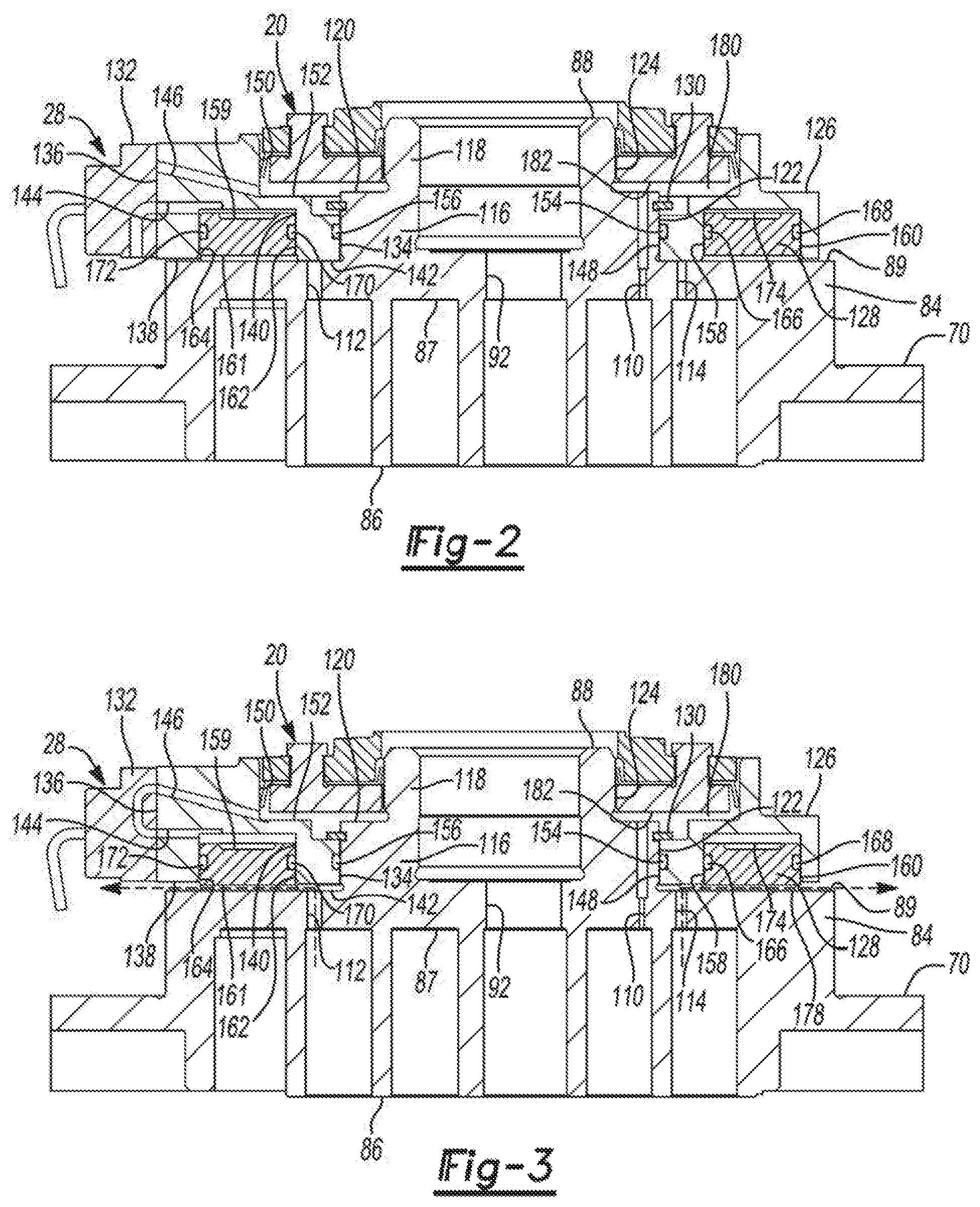
FIG. 2 is a section view of the non-orbiting scroll member and capacity modulation assembly of FIG. 1 in a first operating mode;
FIG. 3 is a section view of the non-orbiting scroll member and capacity modulation assembly of FIG. 1 in a second operating mode;
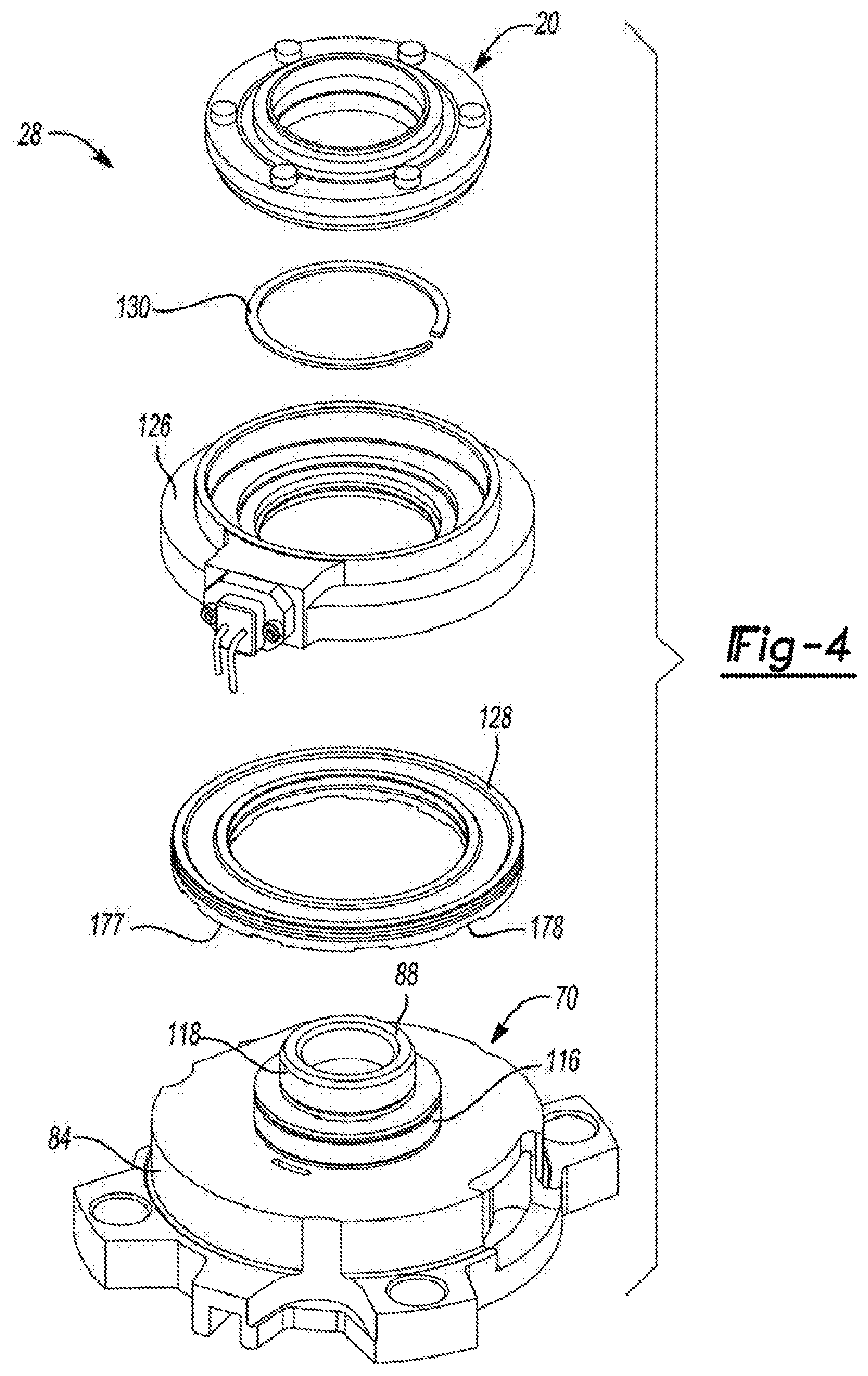
FIG. 4 is a perspective exploded view of the non-orbiting scroll member and capacity modulation assembly of FIG. 1;
FIG. 5 is a section view of an alternate non-orbiting scroll member and capacity modulation assembly according to the present disclosure in a first operating mode;
FIG. 6 is a section view of the non-orbiting scroll member and capacity modulation assembly of FIG. 5 in a second operating mode;
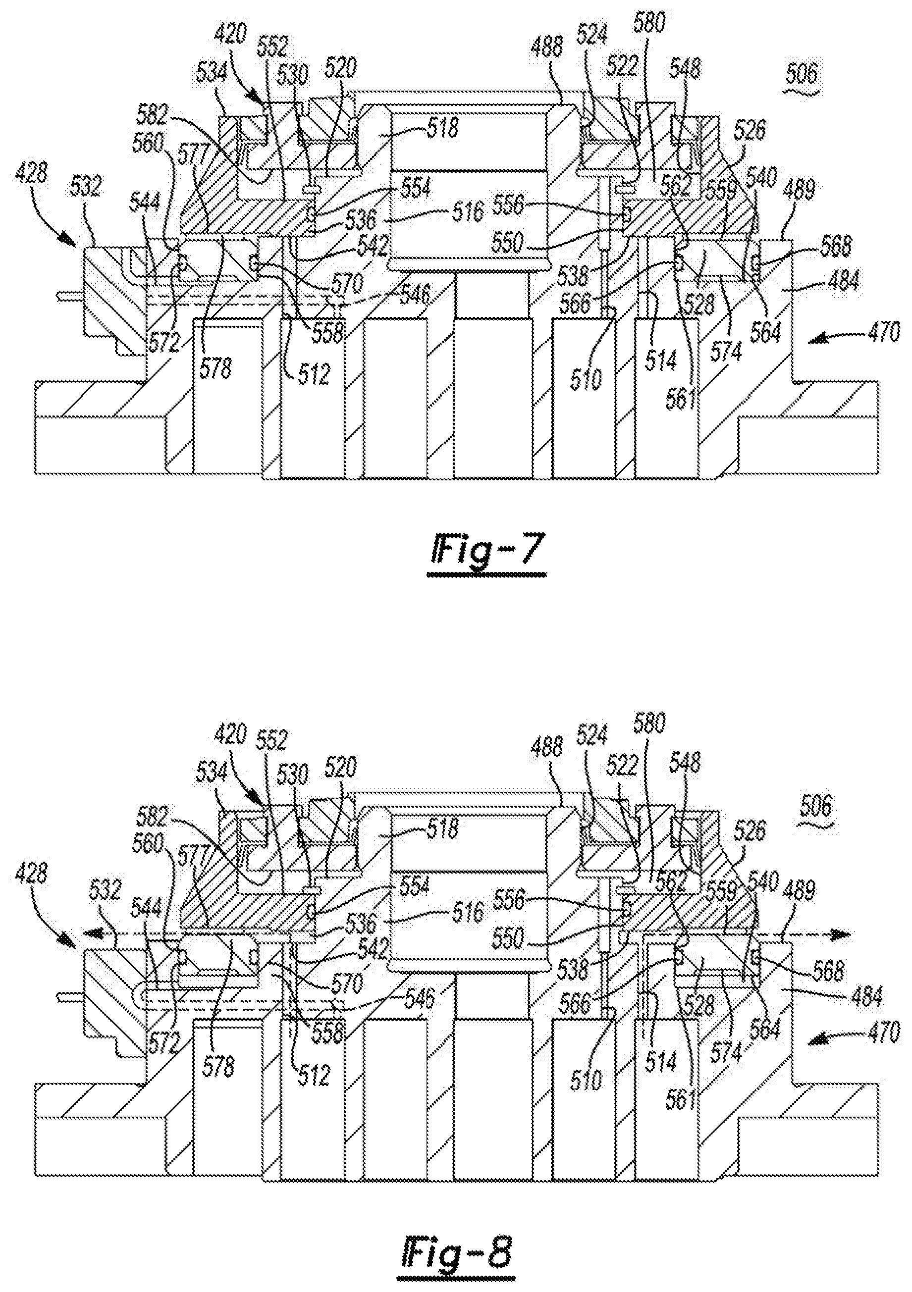
FIG. 7 is a section view of an alternate non-orbiting scroll member and capacity modulation assembly according to the present disclosure in a first operating mode;
FIG. 8 is a section view of the non-orbiting scroll member and capacity modulation assembly of FIG. 7 in a second operating mode;
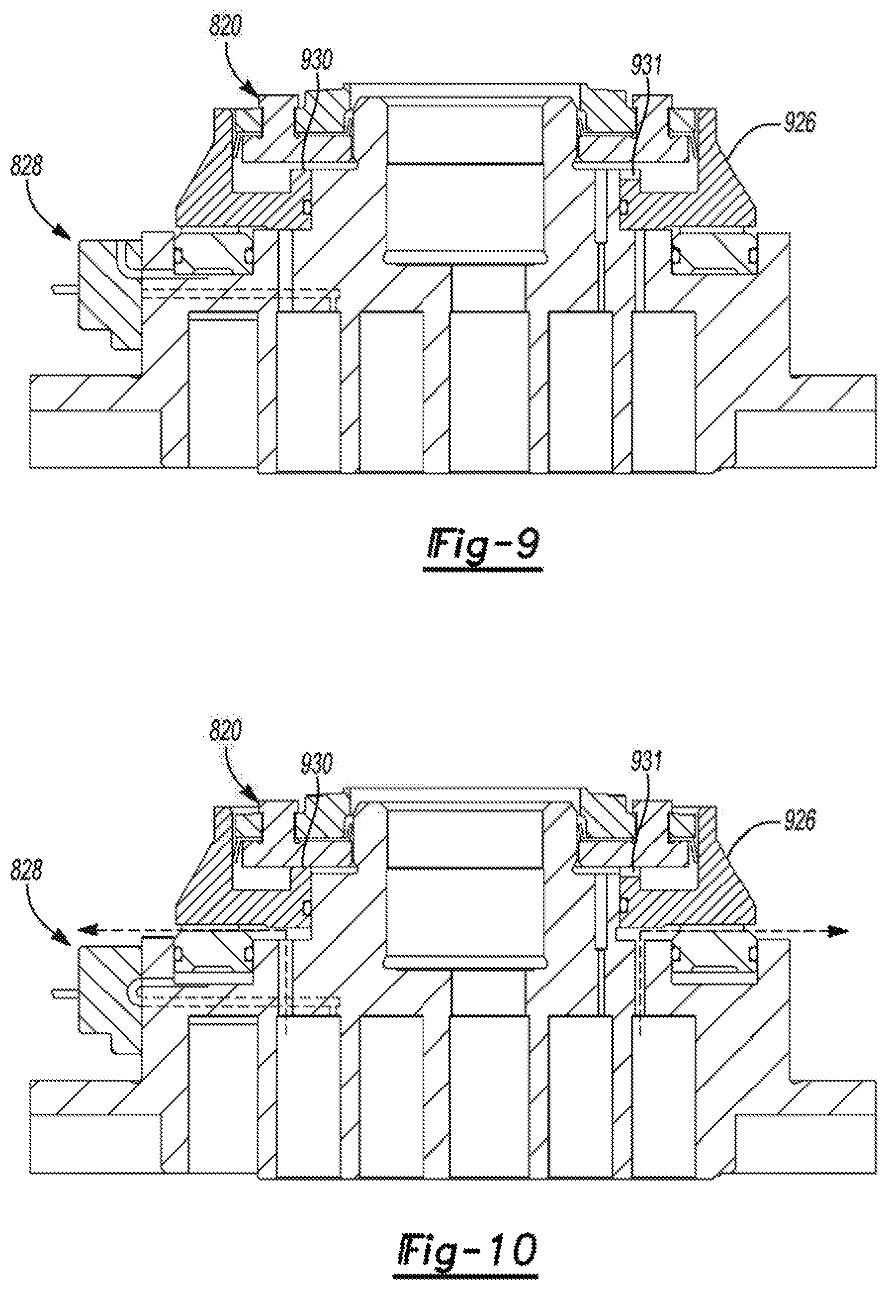
FIG. 9 is a section view of an alternate non-orbiting scroll member and capacity modulation assembly according to the present disclosure in a first operating mode;
FIG. 10 is a section view of the non-orbiting scroll member and capacity modulation assembly of FIG. 9 in a second operating mode;
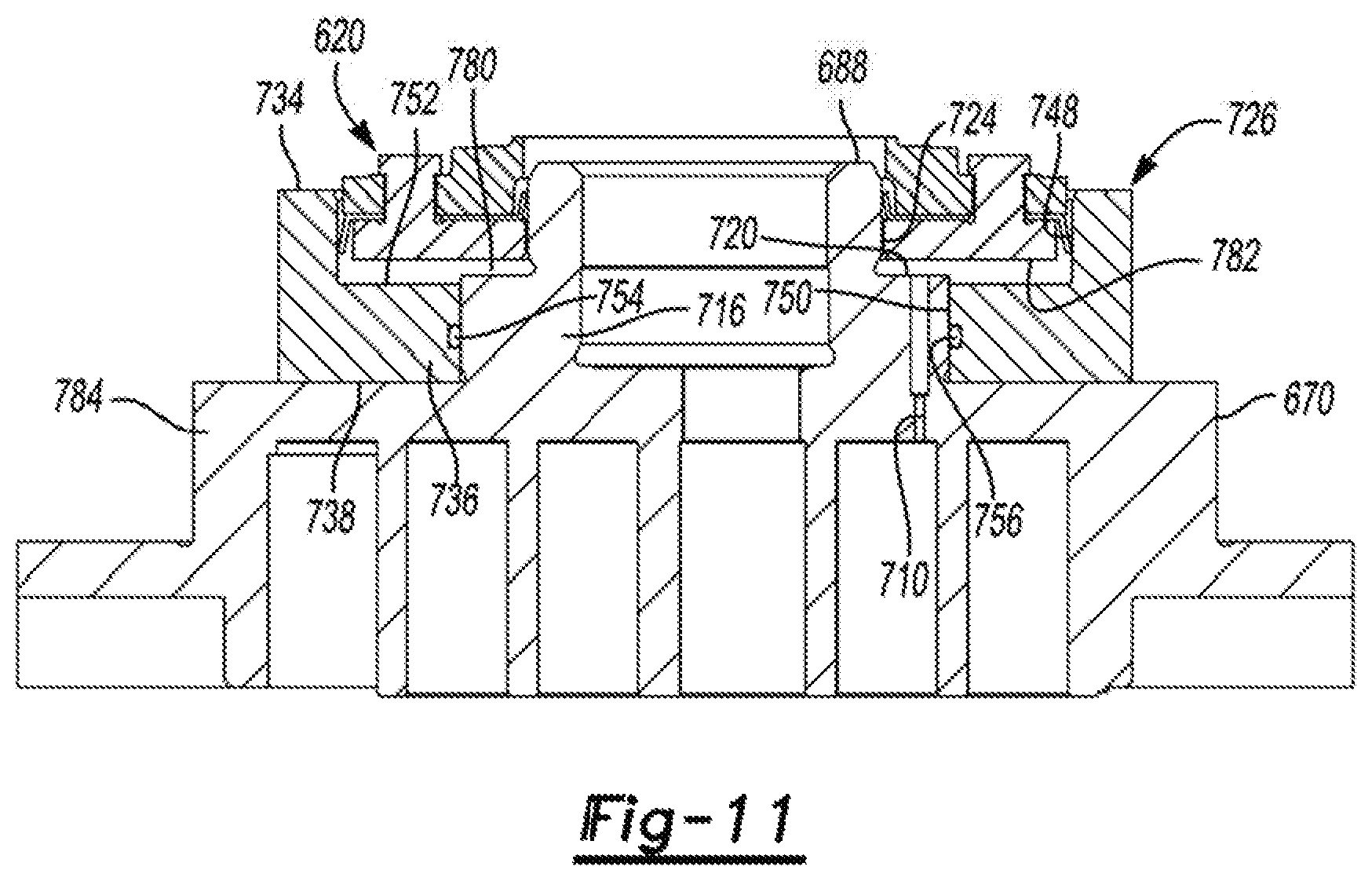
FIG. 11 is a section view of an alternate non-orbiting scroll member according to the present disclosure;
FIG. 12 is a schematic illustration of the capacity modulation assembly of FIG. 2 in the first operating mode;
FIG. 13 is a schematic illustration of the capacity modulation assembly of FIG. 3 in the second operating mode;
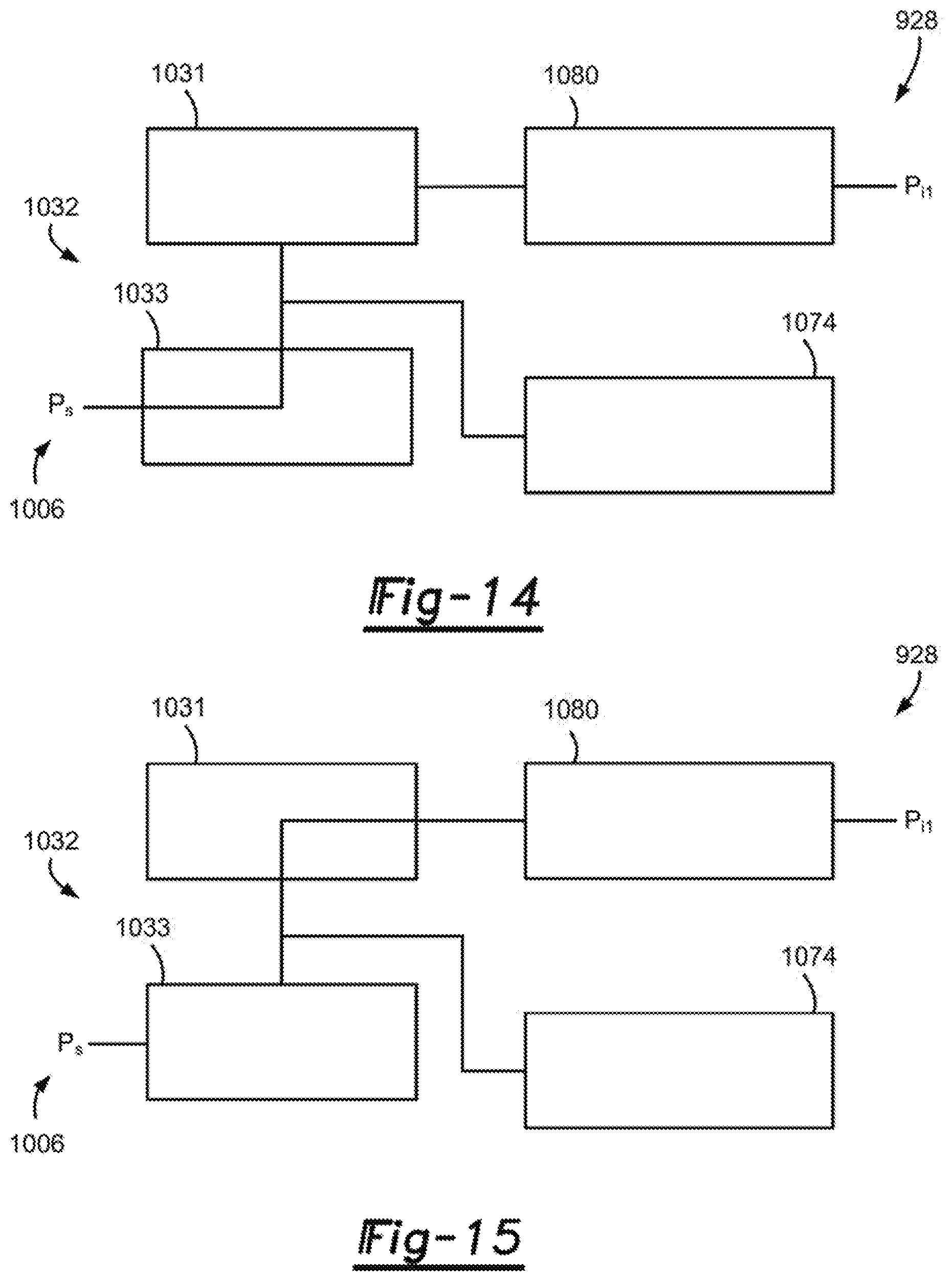
FIG. 14 is a schematic illustration of an alternate capacity modulation assembly in the first operating mode;
FIG. 15 is a schematic illustration of the alternate capacity modulation assembly of FIG. 14 in the second operating mode;
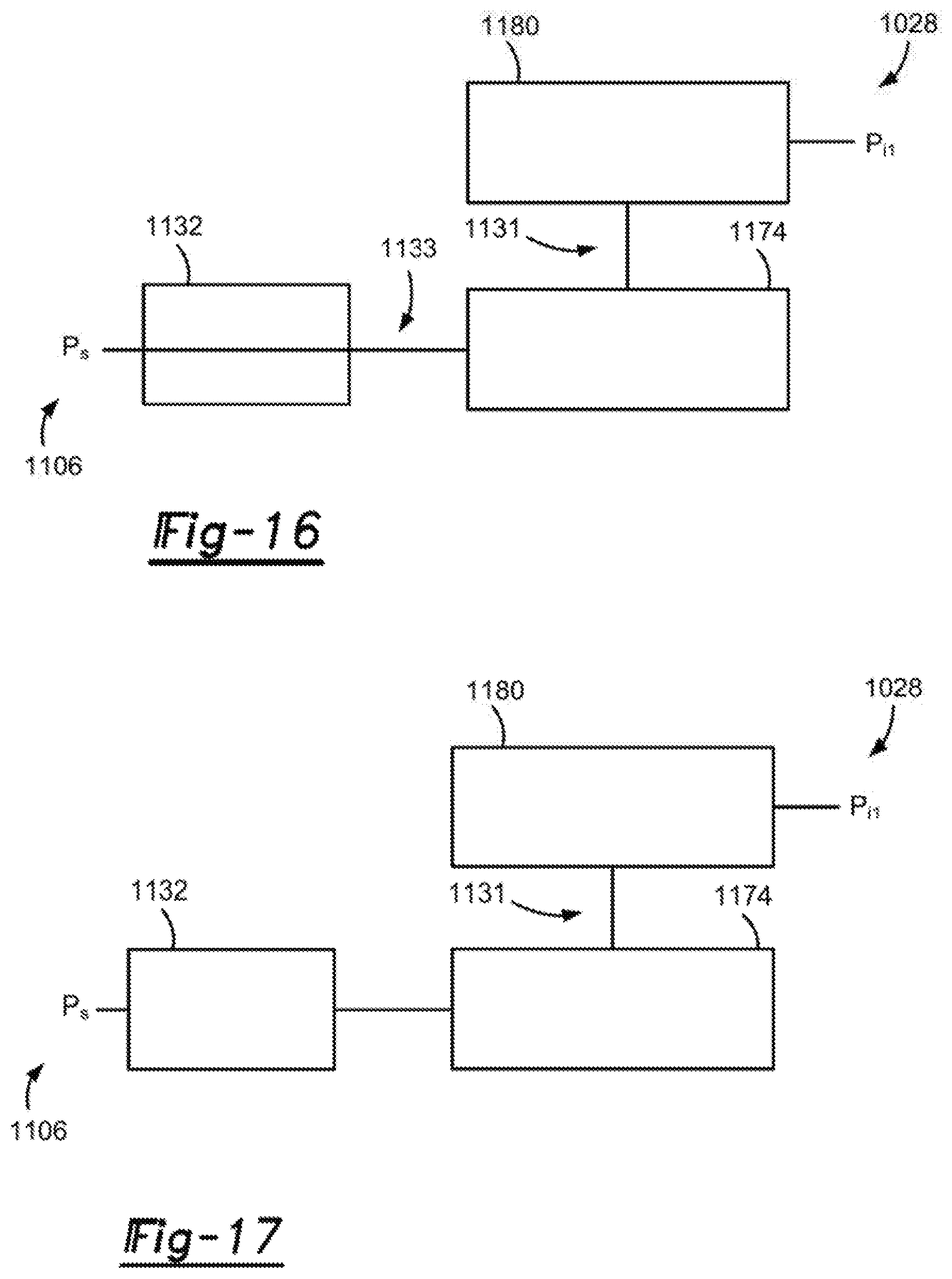
FIG. 16 is a schematic illustration of an alternate capacity modulation assembly in the first operating mode;
FIG. 17 is a schematic illustration of the alternate capacity modulation assembly of FIG. 16 in the second operating mode;
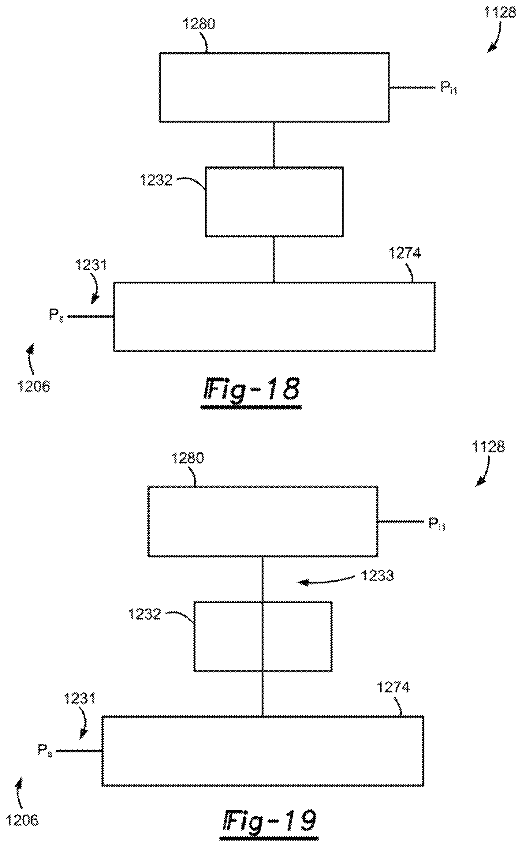
FIG. 18 is a schematic illustration of an alternate capacity modulation assembly in the first operating mode;
FIG. 19 is a schematic illustration of the alternate capacity modulation assembly of FIG. 18 in the second operating mode;
FIG. 20 is a schematic illustration of the capacity modulation assembly of FIG. 7 in the first operating mode;
FIG. 21 is a schematic illustration of the capacity modulation assembly of FIG. 8 in the second operating mode;
FIG. 22 is a schematic illustration of an alternate capacity modulation assembly in the first operating mode;
FIG. 23 is a schematic illustration of the alternate capacity modulation assembly of FIG. 22 in the second operating mode;
FIG. 24 is a schematic illustration of an alternate capacity modulation assembly in the first operating mode;
FIG. 25 is a schematic illustration of the alternate capacity modulation assembly of FIG. 24 in the second operating mode;
FIG. 26 is a schematic illustration of an alternate capacity modulation assembly in the first operating mode;
FIG. 27 is a schematic illustration of the alternate capacity modulation assembly of FIG. 26 in the second operating mode;
FIG. 28 is a section view of an alternate non-orbiting scroll member and capacity modulation assembly according to the present disclosure in a first operating mode;
FIG. 29 is a section view of the non-orbiting scroll member and capacity modulation assembly of FIG. 28 in a second operating mode; and
FIG. 30 is a schematic illustration of the capacity modulation assembly of FIGS. 14 and 15 in a third operating mode.
Corresponding reference numerals indicate corresponding parts throughout the several views of the drawings.
DETAILED DESCRIPTION
The following description is merely exemplary in nature and is not intended to limit the present disclosure, application, or uses. It should be understood that throughout the drawings, corresponding reference numerals indicate like or corresponding parts and features.
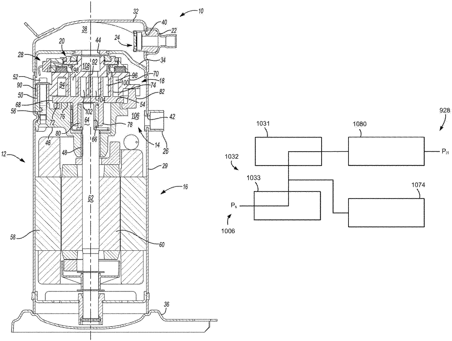
The present teachings are suitable for incorporation in many different types of scroll and rotary compressors, including hermetic machines, open drive machines and non-hermetic machines. For exemplary purposes, a compressor 10 is shown as a hermetic scroll refrigerant-compressor of the low-side type, i.e., where the motor and compressor are cooled by suction gas in the hermetic shell, as illustrated in the vertical section shown in FIG. 1.
With reference to FIG. 1, compressor 10 may include a hermetic shell assembly 12, a bearing housing assembly 14, a motor assembly 16, a compression mechanism 18, a seal assembly 20, a refrigerant discharge fitting 22, a discharge valve assembly 24, a suction gas inlet fitting 26, and a capacity modulation assembly 28. Shell assembly 12 may house bearing housing assembly 14, motor assembly 16, compression mechanism 18, and capacity modulation assembly 28.
Shell assembly 12 may generally form a compressor housing and may include a cylindrical shell 29, an end cap 32 at the upper end thereof, a transversely extending partition 34, and a base 36 at a lower end thereof. End cap 32 and partition 34 may generally define a discharge chamber 38. Discharge chamber 38 may generally form a discharge muffler for compressor 10. While illustrated as including discharge chamber 38, it is understood that the present disclosure applies equally to direct discharge configurations. Refrigerant discharge fitting 22 may be attached to shell assembly 12 at opening 40 in end cap 32. Discharge valve assembly 24 may be located within discharge fitting 22 and may generally prevent a reverse flow condition. Suction gas inlet fitting 26 may be attached to shell assembly 12 at opening 42. Partition 34 may include a discharge passage 44 therethrough providing communication between compression mechanism 18 and discharge chamber 38.
Bearing housing assembly 14 may be affixed to shell 29 at a plurality of points in any desirable manner, such as staking. Bearing housing assembly 14 may include a main bearing housing 46, a bearing 48 disposed therein, bushings 50, and fasteners 52. Main bearing housing 46 may house bearing 48 therein and may define an annular flat thrust bearing surface 54 on an axial end surface thereof. Main bearing housing 46 may include apertures 56 extending therethrough and receiving fasteners 52.
Motor assembly 16 may generally include a motor stator 58, a rotor 60, and a drive shaft 62. Motor stator 58 may be press fit into shell 29. Drive shaft 62 may be rotatably driven by rotor 60 and may be rotatably supported within first bearing 48. Rotor 60 may be press fit on drive shaft 62. Drive shaft 62 may include an eccentric crank pin 64 having a flat 66 thereon.
Compression mechanism 18 may generally include an orbiting scroll 68 and a non-orbiting scroll 70. Orbiting scroll 68 may include an end plate 72 having a spiral vane or wrap 74 on the upper surface thereof and an annular flat thrust surface 76 on the lower surface. Thrust surface 76 may interface with annular flat thrust bearing surface 54 on main bearing housing 46. A cylindrical hub 78 may project downwardly from thrust surface 76 and may have a drive bushing 80 rotatably disposed therein. Drive bushing 80 may include an inner bore in which crank pin 64 is drivingly disposed. Crank pin flat 66 may drivingly engage a flat surface in a portion of the inner bore of drive bushing 80 to provide a radially compliant driving arrangement. An Oldham coupling 82 may be engaged with the orbiting and non-orbiting scrolls 68, 70 to prevent relative rotation therebetween.
With additional reference to FIGS. 2-4, non-orbiting scroll 70 may include an end plate 84 defining a discharge passage 92 and having a spiral wrap 86 extending from a first side 87 thereof, an annular hub 88 extending from a second side 89 thereof opposite the first side, and a series of radially outwardly extending flanged portions 90 (FIG. 1) engaged with fasteners 52. Fasteners 52 may rotationally fix non-orbiting scroll 70 relative to main bearing housing 46 while allowing axial displacement of non-orbiting scroll 70 relative to main bearing housing 46. Spiral wraps 74, 86 may be meshingly engaged with one another defining pockets 94, 96, 98, 100, 102, 104 (FIG. 1). It is understood that pockets 94, 96, 98, 100, 102, 104 change throughout compressor operation.
A first pocket, pocket 94 in FIG. 1, may define a suction pocket in communication with a suction pressure region 106 of compressor 10 operating at a suction pressure (P.sub.s) and a second pocket, pocket 104 in FIG. 1, may define a discharge pocket in communication with a discharge pressure region 108 of compressor 10 operating at a discharge pressure (P.sub.d) via discharge passage 92. Pockets intermediate the first and second pockets, pockets 96, 98, 100, 102 in FIG. 1, may form intermediate compression pockets operating at intermediate pressures between the suction pressure (P.sub.s) and the discharge pressure (P.sub.d).
Referring again to FIGS. 2-4, end plate 84 may additionally include a biasing passage 110 and first and second modulation ports 112, 114. Biasing passage 110 and first and second modulation ports 112, 114 may each be in fluid communication with one of the intermediate compression pockets. Biasing passage 110 may be in fluid communication with one of the intermediate compression pockets operating at a higher pressure than ones of intermediate compression pockets in fluid communication with first and second modulation ports 112, 114.
Annular hub 88 may include first and second portions 116, 118 axially spaced from one another forming a stepped region 120 therebetween. First portion 116 may be located axially between second portion 118 and end plate 84 and may have an outer radial surface 122 defining a first diameter (D.sub.1) greater than or equal to a second diameter (D.sub.2) defined by an outer radial surface 124 of second portion 118.
Capacity modulation assembly 28 may include a modulation valve ring 126, a modulation lift ring 128, a retaining ring 130, and a modulation control valve assembly 132. Modulation valve ring 126 may include an inner radial surface 134, an outer radial surface 136, a first axial end surface 138 defining an annular recess 140 and a valve portion 142, and first and second passages 144, 146. Inner radial surface 134 may include first and second portions 148, 150 defining a second axial end surface 152 therebetween. First portion 148 may define a third diameter (D.sub.3) less than a fourth diameter (D.sub.4) defined by the second portion 150. The first and third diameters (D.sub.1, D.sub.3) may be approximately equal to one another and the first portions 116, 148 may be sealingly engaged with one another via a seal 154 located radially therebetween. More specifically, seal 154 may include an o-ring seal and may be located within an annular recess 156 in first portion 148 of modulation valve ring 126. Alternatively, the o-ring seal could be located in an annular recess in annular hub 88.
Modulation lift ring 128 may be located within annular recess 140 and may include an annular body defining inner and outer radial surfaces 158, 160, and first and second axial end surfaces 159, 161. Inner and outer radial surfaces 158, 160 may be sealingly engaged with sidewalls 162, 164 of annular recess 140 via first and second seals 166, 168. More specifically, first and second seals 166, 168 may include o-ring seals and may be located within annular recesses 170, 172 in inner and outer radial surfaces 158, 160 of modulation lift ring 128. Modulation valve ring 126 and modulation lift ring 128 may cooperate to define a modulation control chamber 174 between annular recess 140 and first axial end surface 159. First passage 144 may be in fluid communication with modulation control chamber 174. Second axial end surface 161 may face end plate 84 and may include a series of protrusions 177 defining radial flow passages 178 therebetween.
Seal assembly 20 may form a floating seal assembly and may be sealingly engaged with non-orbiting scroll 70 and modulation valve ring 126 to define an axial biasing chamber 180. More specifically, seal assembly 20 may be sealingly engaged with outer radial surface 124 of annular hub 88 and second portion 150 of modulation valve ring 126. Axial biasing chamber 180 is a source of intermediate-pressure working fluid (since the axial biasing chamber 180 is in fluid communication with an intermediate-pressure compression pocket via biasing passage 110) and may be defined axially between an axial end surface 182 of seal assembly 20 and second axial end surface 152 of modulation valve ring 126 and stepped region 120 of annular hub 88. Second passage 146 may be in fluid communication with axial biasing chamber 180. In this manner, the passage 146, axial biasing chamber 180, and intermediate-pressure compression pocket form a source of intermediate-pressure working fluid to the modulation control valve 132.
Retaining ring 130 may be axially fixed relative to non-orbiting scroll 70 and may be located within axial biasing chamber 180. More specifically, retaining ring 130 may be located within a recess in first portion 116 of annular hub 88 axially between seal assembly 20 and modulation valve ring 126. Retaining ring 130 may form an axial stop for modulation valve ring 126. Modulation control valve assembly 132 may include a solenoid operated valve and may be in fluid communication with first and second passages 144, 146 in modulation valve ring 126 and suction pressure region 106.
With additional reference to FIGS. 12 and 13, during compressor operation, modulation control valve assembly 132 may be operated in first and second modes. FIGS. 12 and 13 schematically illustrate operation of modulation control valve assembly 132. In the first mode, seen in FIGS. 2 and 12, modulation control valve assembly 132 may provide fluid communication between modulation control chamber 174 and suction pressure region 106. More specifically, modulation control valve assembly 132 may provide fluid communication between first passage 144 and suction pressure region 106 during operation in the first mode. In the second mode, seen in FIGS. 3 and 13, modulation control valve assembly 132 may provide fluid communication between modulation control chamber 174 and axial biasing chamber 180. More specifically, modulation control valve assembly 132 may provide fluid communication between first and second passages 144, 146 during operation in the second mode.
In an alternate capacity modulation assembly 928, seen in FIGS. 14 and 15, a modulation control valve assembly 1032 may include first and second modulation control valves 1031, 1033. Capacity modulation assembly 928 may be incorporated into compressor 10 as discussed below. First modulation control valve 1031 may be in communication with modulation control chamber 1074, biasing chamber 1080, and second modulation control valve 1033. Second modulation control valve 1033 may be in communication with suction pressure region 1006, first modulation control valve 1031, and modulation control chamber 1074. Modulation control valve assembly 1032 may be operated in first and second modes.
In the first mode, seen in FIG. 14, first modulation control valve 1031 may be closed, isolating modulation control chamber 1074 from biasing chamber 1080, and second modulation control valve 1033 may be open, providing communication between modulation control chamber 1074 and suction pressure region 1006. In the second mode, seen in FIG. 15, first modulation control valve 1031 may be open, providing communication between modulation control chamber 1074 and biasing chamber 1080, and second modulation control valve 1033 may be closed, isolating modulation control chamber 1074 from suction pressure region 1006.
Modulation control valve assembly 1032 may be modulated between the first and second modes to create a compressor operating capacity that is between a fully loaded capacity (first mode) and a part loaded capacity (second mode). Pulse-width-modulation of the opening and closing of first and second modulation control valves 1031, 1033 may be utilized to create this intermediate capacity. Second modulation control valve 1033 may be open during the first mode as seen in FIG. 14. Alternatively, second modulation control valve 1033 may be opened, for example, between 0.2 and 1.0 seconds when transitioning from the second mode to the first mode and then closed to be ready for transitioning to the second mode. This allows the modulation control chamber 1074 to reach suction pressure (P.sub.s) to allow compressor operation in the first mode.
Alternatively, modulation control valve assembly 1032 may be modulated between the second mode and a third mode. The third mode is schematically illustrated in FIG. 30 and provides an unloaded (zero capacity) condition. In the third mode, first and second modulation control valves 1031, 1033 may be open. Therefore, modulation control chamber 1074 and biasing chamber 1080 are both in communication with suction pressure region 1006. Modulation control valve assembly 1032 may be modulated between the second and third modes to create a compressor operating capacity that is between the part loaded capacity (second mode) and the unloaded capacity (third mode). Pulse-width-modulation of the opening and closing of first and second modulation control valves 1031, 1033 may be utilized to create this intermediate capacity.
Alternatively, modulation control valve assembly 1032 may be modulated between the first and third modes to create a compressor operating capacity that is between the fully loaded capacity (first mode) and the unloaded capacity (third mode). Pulse-width-modulation of the opening and closing of first and second modulation control valves 1031, 1033 may be utilized to create this intermediate capacity. When transitioning from the third mode to the first mode, second modulation control valve 1033 may remain open and first modulation control valve 1031 may be modulated between opened and closed positions. Alternatively, second modulation control valve 1033 may be closed when transitioning from the third mode to the first mode. In such arrangements, second modulation control valve 1033 may be closed after first modulation control valve 1031 by a delay (e.g., less than one second) to ensure that modulation control chamber 1074 is maintained at suction pressure (P.sub.s) and does not experience additional biasing pressure (P.sub.i1).
An alternate capacity modulation assembly 1028 is shown in FIGS. 16 and 17. Capacity modulation assembly 1028 may be incorporated into compressor 10 as discussed below. In the arrangement of FIGS. 16 and 17, modulation control chamber 1174 may be in communication with biasing chamber 1180 via a first passage 1131. Modulation control valve assembly 1132 may be in communication with modulation control chamber 1174 and suction pressure region 1106. Modulation control valve assembly 1132 may be operated in first and second modes.
In the first mode, seen in FIG. 16, modulation control valve assembly 1132 may be open, providing communication between modulation control chamber 1174 via a second passage 1133. First passage 1131 may define a greater flow restriction than second passage 1133. The greater flow restriction of first passage 1131 relative to second passage 1133 may generally prevent a total loss of biasing pressure within biasing chamber 1180 during the first mode. In the second mode, seen in FIG. 17, modulation control valve assembly 1132 may be closed, isolating modulation control chamber 1174 from suction pressure region 1106.
Another alternate capacity modulation assembly 1128 is shown in FIGS. 18 and 19. Capacity modulation assembly 1128 may be incorporated into compressor 10 as discussed below. In the arrangement of FIGS. 18 and 19, modulation control chamber 1274 may be in communication with suction pressure region 1206 via a first passage 1231. Modulation control valve assembly 1232 may be in communication with modulation control chamber 1274 and biasing chamber 1280. Modulation control valve assembly 1232 may be operated in first and second modes.
In the first mode, seen in FIG. 18, modulation control valve assembly 1232 may be closed, isolating modulation control chamber 1274 from biasing chamber 1280. In the second mode, seen in FIG. 19, modulation control valve assembly 1232 may be open, providing communication between modulation control chamber 1274 and biasing chamber 1280 via a second passage 1233. First passage 1231 may define a greater flow restriction than second passage 1233. The greater flow restriction of first passage 1231 relative to second passage 1233 may generally prevent a total loss of biasing pressure within biasing chamber 1280 during the second mode.
Modulation valve ring 126 may define a first radial surface area (A.sub.1) facing away from non-orbiting scroll 70 radially between first and second portions 148, 150 of inner radial surface 134 of modulation valve ring 126 (A.sub.1=(.pi.)(D.sub.4.sup.2-D.sub.3.sup.2)/4). Inner sidewall 162 may define a diameter (D.sub.5) less than a diameter (D.sub.6) defined by outer sidewall 164. Modulation valve ring 126 may define a second radial surface area (A.sub.2) opposite first radial surface area (A.sub.1) and facing non-orbiting scroll 70 radially between sidewalls 162, 164 of inner radial surface 134 of modulation valve ring 126 (A.sub.2=(.pi.)(D.sub.6.sup.2-D.sub.5.sup.2)/4). First radial surface area (A.sub.1) may be less than second radial surface area (A.sub.2). Modulation valve ring 126 may be displaced between first and second positions based on the pressure provided to modulation control chamber 174 by modulation control valve assembly 132. Modulation valve ring 126 may be displaced by fluid pressure acting directly thereon, as discussed below.
A first intermediate pressure (P.sub.i1) within axial biasing chamber 180 applied to first radial surface area (A.sub.1) may provide a first axial force (F.sub.1) urging modulation valve ring 126 axially toward non-orbiting scroll 70 during both the first and second modes. When modulation control valve assembly 132 is operated in the first mode, modulation valve ring 126 may be in the first position (FIG. 2). In the first mode, suction pressure (P.sub.s) within modulation control chamber 174 may provide a second axial force (F.sub.2) opposite first axial force (F.sub.1) urging modulation valve ring 126 axially away from non-orbiting scroll 70. First axial force (F.sub.1) may be greater than second axial force (F.sub.2). Therefore, modulation valve ring 126 may be in the first position during operation of modulation control valve assembly 132 in the first mode. The first position may include valve portion 142 of modulation valve ring 126 abutting end plate 84 and closing first and second modulation ports 112, 114.
When modulation control valve assembly 132 is operated in the second mode, modulation valve ring 126 may be in the second position (FIG. 3). In the second mode, first intermediate pressure (P.sub.i1) within modulation control chamber 174 may provide a third axial force (F.sub.3) acting on modulation valve ring 126 and opposite first axial force (F.sub.1) urging modulation valve ring 126 axially away from non-orbiting scroll 70. Since modulation control chamber 174 and axial biasing chamber 180 are in fluid communication with one another during operation of the modulation control valve assembly 132 in the second mode, both may operate at approximately the same first intermediate pressure (P.sub.i1). Third axial force (F.sub.3) may be greater than first axial force (F.sub.1) since second radial surface area (A.sub.2) is greater than first radial surface area (A.sub.1). Therefore, modulation valve ring 126 may be in the second position during operation of modulation control valve assembly 132 in the second mode. The second position may include valve portion 142 of modulation valve ring 126 being displaced from end plate 84 and opening first and second modulation ports 112, 114. Modulation valve ring 126 may abut retaining ring 130 when in the second position.
Modulation valve ring 126 and modulation lift ring 128 may be forced in axial directions opposite one another during operation of modulation control valve assembly 132 in the second mode. More specifically, modulation valve ring 126 may be displaced axially away from end plate 84 and modulation lift ring 128 may be urged axially toward end plate 84. Protrusions 177 of modulation lift ring 128 may abut end plate 84 and first and second modulation ports 112, 114 may be in fluid communication with suction pressure region 106 via radial flow passages 178 when modulation valve ring 126 is in the second position.
An alternate capacity modulation assembly 228 is illustrated in FIGS. 5 and 6. Capacity modulation assembly 228 may be generally similar to capacity modulation assembly 28 and may be incorporated into compressor 10 as discussed below. Therefore, it is understood that the description of capacity modulation assembly 28 applies equally to capacity modulation assembly 228 with the exceptions noted below. Modulation valve ring 326 may include axially extending protrusions 330 in place of retaining ring 130 of capacity modulation assembly 28. Protrusions 330 may be circumferentially spaced from one another, forming flow paths 331 therebetween. When modulation valve ring 326 is displaced from the first position (FIG. 5) to the second position (FIG. 6), protrusions 330 may abut seal assembly 220 to provide an axial stop for modulation valve ring 326.
An alternate capacity modulation assembly 1528 is illustrated in FIGS. 28 and 29. Capacity modulation assembly 1528 may be generally similar to capacity modulation assembly 28 and may be incorporated into compressor 10 as discussed below. Therefore, it is understood that the description of capacity modulation assembly 28 applies equally to capacity modulation assembly 1528 with the exceptions noted below. Modulation valve ring 1626 may include axially extending protrusions 1630 and modulation lift ring 1628 may include axially extending protrusions 1632. Protrusions 1630 may extend axially beyond and radially inward relative to protrusions 1632. When modulation valve ring 1626 is displaced from the first position (FIG. 28) to the second position (FIG. 29), protrusions 1630 may abut protrusions 1632 to provide an axial stop for modulation valve ring 1626.
An alternate non-orbiting scroll 470 and capacity modulation assembly 428 are illustrated in FIGS. 7 and 8. End plate 484 of non-orbiting scroll 470 may include a biasing passage 510, first and second modulation ports 512, 514, an annular recess 540, and first and second passages 544, 546. Biasing passage 510, first and second modulation ports 512, 514, and second passage 546 may each be in fluid communication with one of the intermediate compression pockets. Biasing passage 510 may be in fluid communication with one of the intermediate compression pockets operating at a higher pressure than ones of intermediate compression pockets in fluid communication with first and second modulation ports 512, 514. The second passage 546 is a source of intermediate-pressure working fluid to modulation control valve 532 since the passage 546 is in fluid communication with an intermediate-pressure compression pocket. In the arrangement shown in FIGS. 7 and 8, second passage 546 may be in communication with one of the intermediate compression pockets operating at a higher pressure than or equal to the intermediate compression pocket in communication with biasing passage 510.
Annular hub 488 may include first and second portions 516, 518 axially spaced from one another forming a stepped region 520 therebetween. First portion 516 may be located axially between second portion 518 and end plate 484 and may have an outer radial surface 522 defining a diameter (D.sub.7) greater than or equal to a diameter (D.sub.8) defined by an outer radial surface 524 of second portion 518.
Capacity modulation assembly 428 may include a modulation valve ring 526, a modulation lift ring 528, a retaining ring 530, and a modulation control valve assembly 532. Modulation valve ring 526 may include an axial leg 534 and a radial leg 536. Radial leg 536 may include a first axial end surface 538 facing end plate 484 and defining a valve portion 542 and a second axial end surface 552 facing seal assembly 420. An inner radial surface 548 of axial leg 534 may define a diameter (D.sub.9) greater than a diameter (D.sub.10) defined by an inner radial surface 550 of radial leg 536. The diameters (D.sub.7, D.sub.10) may be approximately equal to one another and first portion 516 of annular hub 488 may be sealingly engaged with radial leg 536 of modulation valve ring 526 via a seal 554 located radially therebetween. More specifically, seal 554 may include an o-ring seal and may be located within an annular recess 556 in inner radial surface 550 of modulation valve ring 526.
Modulation lift ring 528 may be located within annular recess 540 and may include an annular body defining inner and outer radial surfaces 558, 560, and first and second axial end surfaces 559, 561. Annular recess 540 may extend axially into second side 489 of end plate 484. Inner and outer radial surfaces 558, 560 may be sealingly engaged with sidewalls 562, 564 of annular recess 540 via first and second seals 566, 568. More specifically, first and second seals 566, 568 may include o-ring seals and may be located within annular recesses 570, 572 in inner and outer radial surfaces 558, 560 of modulation lift ring 528. End plate 484 and modulation lift ring 528 may cooperate to define a modulation control chamber 574 between annular recess 540 and second axial end surface 561. First passage 544 may be in fluid communication with modulation control chamber 574. First axial end surface 559 may face modulation valve ring 526 and may include a series of protrusions 577 defining radial flow passages 578 therebetween.
Seal assembly 420 may form a floating seal assembly and may be sealingly engaged with non-orbiting scroll 470 and modulation valve ring 526 to define an axial biasing chamber 580. More specifically, seal assembly 420 may be sealingly engaged with outer radial surface 524 of annular hub 488 and inner radial surface 548 of modulation valve ring 526. Axial biasing chamber 580 may be defined axially between an axial end surface 582 of seal assembly 420 and second axial end surface 552 of modulation valve ring 526 and by stepped region 520 of annular hub 488.
Retaining ring 530 may be axially fixed relative to non-orbiting scroll 470 and may be located within axial biasing chamber 580. More specifically, retaining ring 530 may be located within a recess in first portion 516 of annular hub 488 axially between seal assembly 420 and modulation valve ring 526. Retaining ring 530 may form an axial stop for modulation valve ring 526. Modulation control valve assembly 532 may include a solenoid operated valve and may be in fluid communication with first and second passages 544, 546 in end plate 484 and suction pressure region 506.
With additional reference to FIGS. 20 and 21, during compressor operation, modulation control valve assembly 532 may be operated in first and second modes. FIGS. 20 and 21 schematically illustrate operation of modulation control valve assembly 532. In the first mode, seen in FIGS. 7 and 20, modulation control valve assembly 532 may provide fluid communication between modulation control chamber 574 and suction pressure region 506. More specifically, modulation control valve assembly 532 may provide fluid communication between first passage 544 and suction pressure region 506 during operation in the first mode. In the second mode, seen in FIGS. 8 and 21, modulation control valve assembly 532 may provide fluid communication between modulation control chamber 574 and second passage 546.
In an alternate capacity modulation assembly 1228, seen in FIGS. 22 and 23, a modulation control valve assembly 1332 may include first and second modulation control valves 1331, 1333. Capacity modulation assembly 1228 may be incorporated into compressor 10 as discussed below. First modulation control valve 1331 may be in communication with suction pressure region 1306, modulation control chamber 1374 and second modulation control valve 1333. Second modulation control valve 1333 may be in communication with second passage 1346 (similar to second passage 546), modulation control chamber 1374 and first modulation control valve 1331. Modulation control valve assembly 1332 may be operated in first and second modes. Similar to the capacity modulation assembly 428, biasing chamber 1380 and first passage 1310 (similar to biasing passage 510) may be isolated from communication with modulation control valve assembly 1332 and modulation control chamber 1374 during both the first and second modes.
In the first mode, seen in FIG. 22, first modulation control valve 1331 may be open, providing communication between modulation control chamber 1374 and suction pressure region 1306, and second modulation control valve 1333 may be closed, isolating modulation control chamber 1374 from second passage 1346. In the second mode, seen in FIG. 23, first modulation control valve 1331 may be closed, isolating modulation control chamber 1374 from suction pressure region 1306, and second modulation control valve 1333 may be open, providing communication between modulation control chamber 1374 and second passage 1346.
An alternate capacity modulation assembly 1328 is shown in FIGS. 24 and 25. Capacity modulation assembly 1328 may be incorporated into compressor 10 as discussed below. In the arrangement of FIGS. 24 and 25, modulation control chamber 1474 may be in communication with second passage 1446 (similar to second passage 546) and modulation control valve assembly 1432. Modulation control valve assembly 1432 may be in communication with modulation control chamber 1474 and suction pressure region 1406. Modulation control valve assembly 1432 may be operated in first and second modes. Similar to capacity modulation assembly 428, biasing chamber 1480 and first passage 1410 (similar to biasing passage 510) may be isolated from communication with modulation control valve assembly 1432 and modulation control chamber 1474 during both the first and second modes.
In the first mode, seen in FIG. 24, modulation control valve assembly 1432 may be open, providing communication between modulation control chamber 1474 and suction pressure region 1406 via a third passage 1433. Second passage 1446 may define a greater flow restriction than third passage 1433. In the second mode, seen in FIG. 25, modulation control valve assembly 1432 may be closed, isolating modulation control chamber 1474 from communication with suction pressure region 1406.
Another capacity modulation assembly 1428 is shown in FIGS. 26 and 27. Capacity modulation assembly 1428 may be incorporated into compressor 10 as discussed below. In the arrangement of FIGS. 26 and 27, modulation control chamber 1574 may be in communication with suction pressure region 1506 via a third passage 1533. Modulation control valve assembly 1532 may be in communication with modulation control chamber 1574 and second passage 1546 (similar to second passage 546). Modulation control valve assembly 1532 may be operated in first and second modes. Similar to capacity modulation assembly 428, biasing chamber 1580 and first passage 1510 (similar to biasing passage 510) may be isolated form communication with modulation control valve assembly 1532 and modulation control chamber 1574 during both the first and second modes.
In the first mode, seen in FIG. 26, modulation control valve assembly 1532 may be closed, isolating modulation control chamber 1574 from communication with a biasing pressure. In the second mode, seen in FIG. 27, modulation control valve assembly 1532 may be open, providing communication between modulation control chamber 1574 and a biasing pressure via second passage 1546. Third passage 1533 may provide a greater flow restriction than second passage 1546.
Modulation valve ring 526 may define a first radial surface area (A.sub.11) facing away from non-orbiting scroll 470 radially between inner radial surfaces 548, 550 of modulation valve ring 526 (A.sub.11=(.pi.)(D.sub.9.sup.2-D.sub.10.sup.2)/4). Sidewalls 562, 564 may define inner and outer diameters (D.sub.11, D.sub.12). Modulation lift ring 528 may define a second radial surface area (A.sub.22) opposite first radial surface area (A.sub.11) and facing non-orbiting scroll 70 radially between sidewalls 562, 564 of end plate 484 (A.sub.22=(.pi.)(D.sub.12.sup.2-D.sub.11.sup.2)/4). First radial surface area (A.sub.11) may be greater than second radial surface area (A.sub.22). Modulation valve ring 526 may be displaced between first and second positions based on the pressure provided to modulation control chamber 574 by modulation control valve assembly 532. Modulation lift ring 528 may displace modulation valve ring 526, as discussed below. The arrangement shown in FIGS. 7 and 8 generally provides for a narrower non-orbiting scroll 470 and capacity modulation assembly 428 arrangements. However, it is understood that alternate arrangements may exist where the second radial surface area (A.sub.22) is greater than the first radial surface area (A.sub.11), as in FIGS. 2 and 3.
A second intermediate pressure (P.sub.i2) within axial biasing chamber 580 applied to first radial surface area (A.sub.11) may provide a first axial force (F.sub.11) urging modulation valve ring 526 axially toward non-orbiting scroll 470 during both the first and second modes. When modulation control valve assembly 532 is operated in the first mode, modulation valve ring 526 may be in the first position (FIG. 7). In the first mode, suction pressure (P.sub.s) within modulation control chamber 574 may provide a second axial force (F.sub.22) opposite first axial force (F.sub.11). Modulation lift ring 528 may apply second axial force (F.sub.22) to modulation valve ring 526 to bias modulation valve ring 526 axially away from non-orbiting scroll 470. First axial force (F.sub.11) may be greater than second axial force (F.sub.22). Therefore, modulation valve ring 526 may be in the first position during operation of modulation control valve assembly 532 in the first mode. The first position may include valve portion 542 of modulation valve ring 526 abutting end plate 484 and closing first and second modulation ports 512, 514.
When modulation control valve assembly 532 is operated in the second mode, modulation valve ring 526 may be in the second position (FIG. 8). In the second mode, a third intermediate pressure (P.sub.i3) from the intermediate compression pocket in fluid communication with second passage 546 may provide a third axial force (F.sub.33) opposite first axial force (F.sub.11) urging modulation lift ring 528 axially toward modulation valve ring 526. Modulation lift ring 528 may apply third axial force (F.sub.33) to modulation valve ring 526 to bias modulation valve ring 526 axially away from non-orbiting scroll 470. Third axial force (F.sub.33) may be greater than first axial force (F.sub.11) even when second radial surface area (A.sub.22) is less than first radial surface area (A.sub.11) since modulation control chamber 574 operates at a higher pressure than axial biasing chamber 580 during the second mode (P.sub.i3>P.sub.i2). Modulation control chamber 574 may operate at the same pressure as axial biasing chamber 580 and therefore A.sub.22 may be greater than A.sub.11. Therefore, modulation valve ring 526 may be in the second position during operation of modulation control valve assembly 532 in the second mode. The second position may include valve portion 542 of modulation valve ring 526 being displaced from end plate 484 and opening first and second modulation ports 512, 514. Modulation valve ring 526 may abut retaining ring 530 when in the second position.
Modulation valve ring 526 and modulation lift ring 528 may be forced in the same axial direction during operation of modulation control valve assembly 532 in the second mode. More specifically, modulation valve ring 526 and modulation lift ring 528 may both be displaced axially away from end plate 484. Protrusions 577 of modulation lift ring 528 may abut modulation valve ring 526 and first and second modulation ports 512, 514 may be in fluid communication with suction pressure region 506 via radial flow passages 578 when modulation valve ring 526 is in the second position.
An alternate capacity modulation assembly 828 is illustrated in FIGS. 9 and 10. Capacity modulation assembly 828 may be generally similar to capacity modulation assembly 428. Therefore, it is understood that the description of capacity modulation assembly 428 applies equally to capacity modulation assembly 828 with the exceptions noted below. Modulation valve ring 926 may include axially extending protrusions 930 in place of retaining ring 530 of capacity modulation assembly 428. Protrusions 930 may be circumferentially spaced from one another, forming flow paths 931 therebetween. When modulation valve ring 926 is displaced from the first position (FIG. 9) to the second position (FIG. 10), protrusions 930 may abut seal assembly 820 to provide an axial stop for modulation valve ring 926.
In an alternate arrangement, seen in FIG. 11, non-orbiting scroll 670 may be used in compressor 10 in place of non-orbiting scroll 70 and capacity modulation assembly 28. Non-orbiting scroll 670 may be similar to non-orbiting scroll 70, with the exception of first and second modulation ports 112, 114. Instead of capacity modulation assembly 28, non-orbiting scroll 670 may have an outer hub 726 engaged therewith. More specifically, outer hub 726 may include an axial leg 734 and a radial leg 736.
Radial leg 736 may include a first axial end surface 738 facing end plate 784 and a second axial end surface 752 facing seal assembly 620. First portion 716 of annular hub 688 may be sealingly engaged with radial leg 736 of outer hub 726 via a seal 754 located radially therebetween. More specifically, seal 754 may include an o-ring seal and may be located within an annular recess 756 in inner radial surface 750 of outer hub 726.
Seal assembly 620 may form a floating seal assembly and may be sealingly engaged with non-orbiting scroll 670 and outer hub 726 to define an axial biasing chamber 780. More specifically, seal assembly 620 may be sealingly engaged with outer radial surface 724 of annular hub 688 and inner radial surface 748 of axial leg 734. Axial biasing chamber 780 may be defined axially between an axial end surface 782 of seal assembly 620 and second axial end surface 752 of outer hub 726 and stepped portion 720 of annular hub 688. Biasing passage 710 may extend through stepped region 720 of annular hub 688 to provide fluid communication between axial biasing chamber 780 and an intermediate compression pocket.
Outer hub 726 may be press fit on non-orbiting scroll 670 and fixed thereto without the use of fasteners by the press-fit engagement, as well as by pressure within axial biasing chamber 780 acting on second axial end surface 752 during compressor operation. Therefore, a generally common non-orbiting scroll 70, 270, 470, 670 may be used for a variety of applications including compressors with and without capacity modulation assemblies or first and second modulation ports 112, 512, 114, 514 of non-orbiting scrolls 70, 270, 470.
* * * * *
D00000
D00001
D00002
D00003
D00004
D00005
D00006
D00007
D00008
D00009
D00010
D00011
D00012

D00013
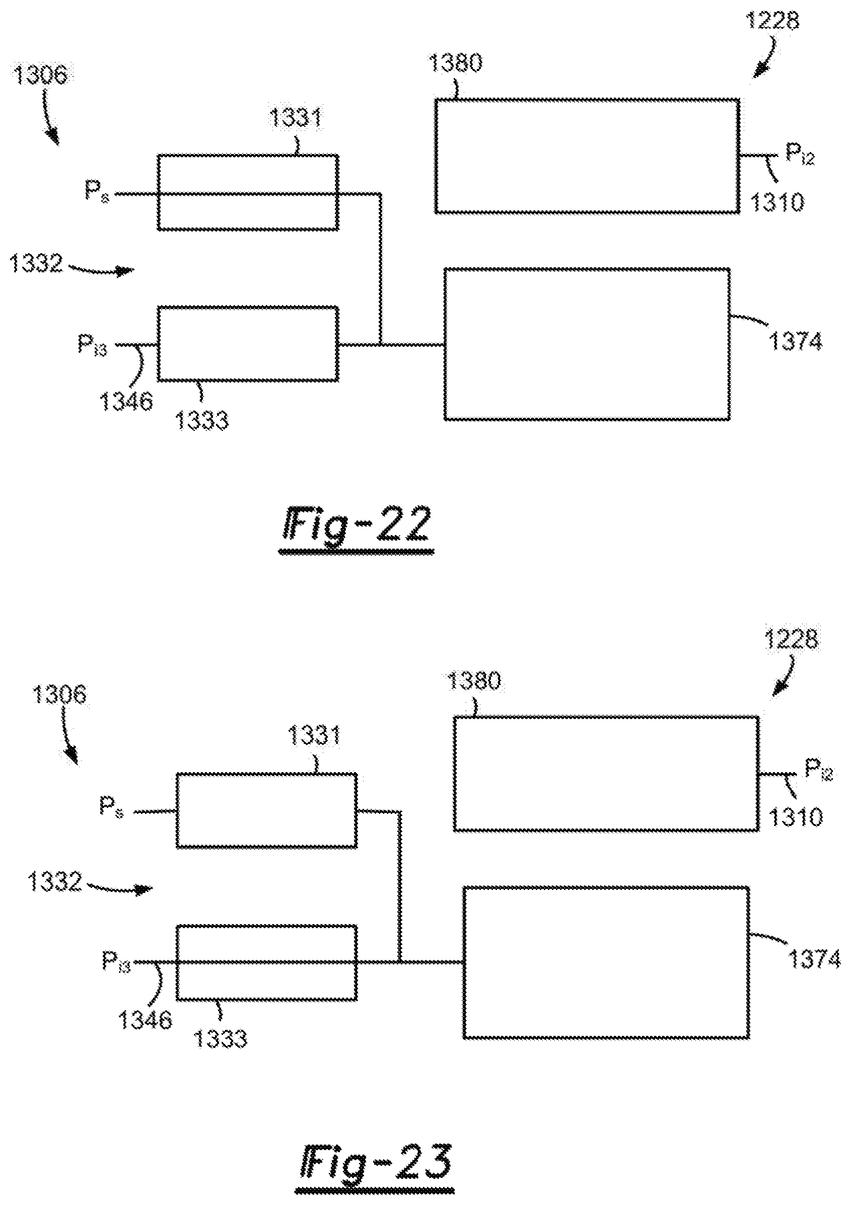
D00014
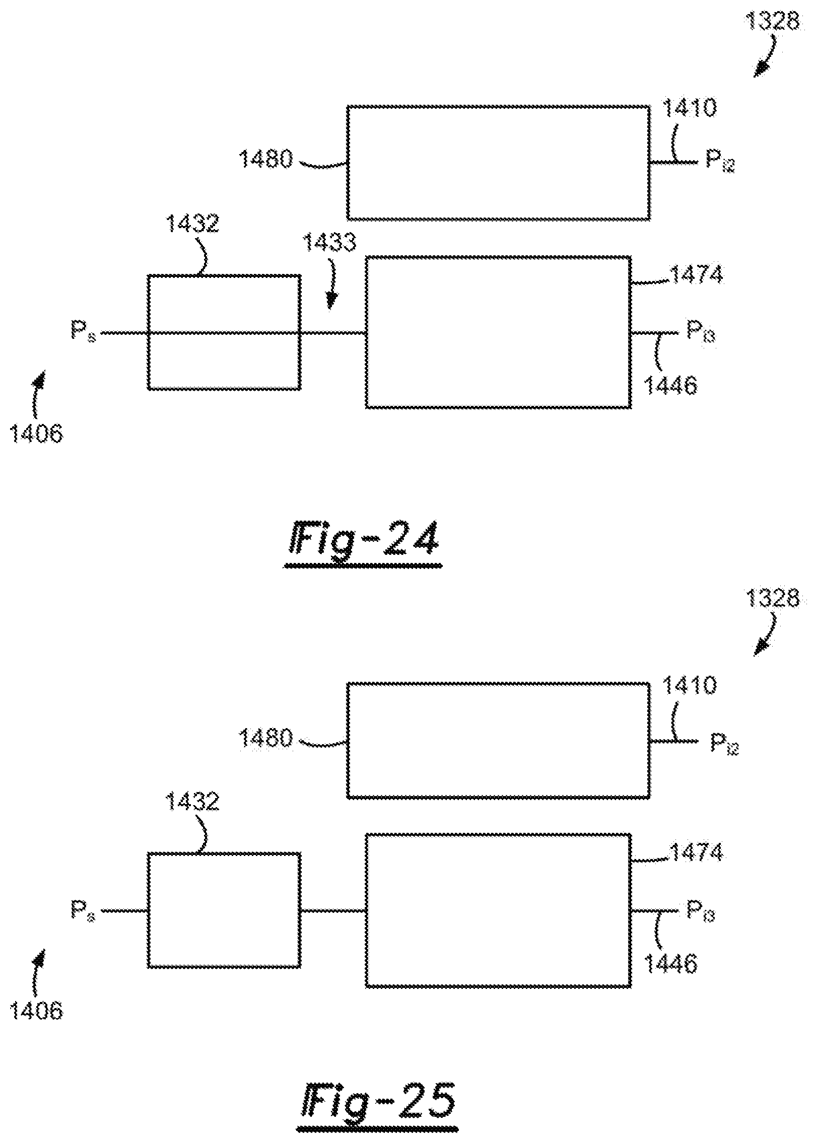
D00015
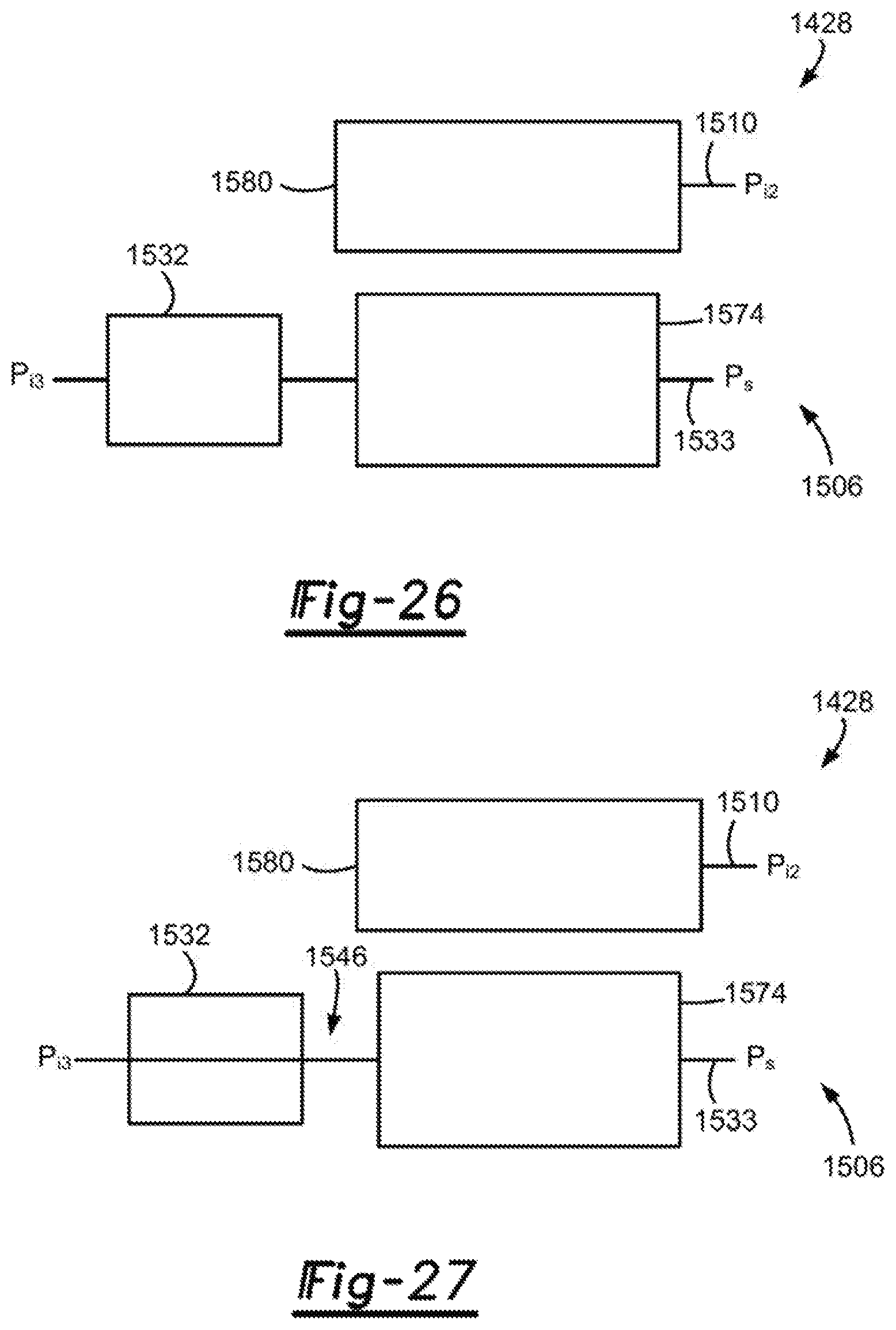
D00016
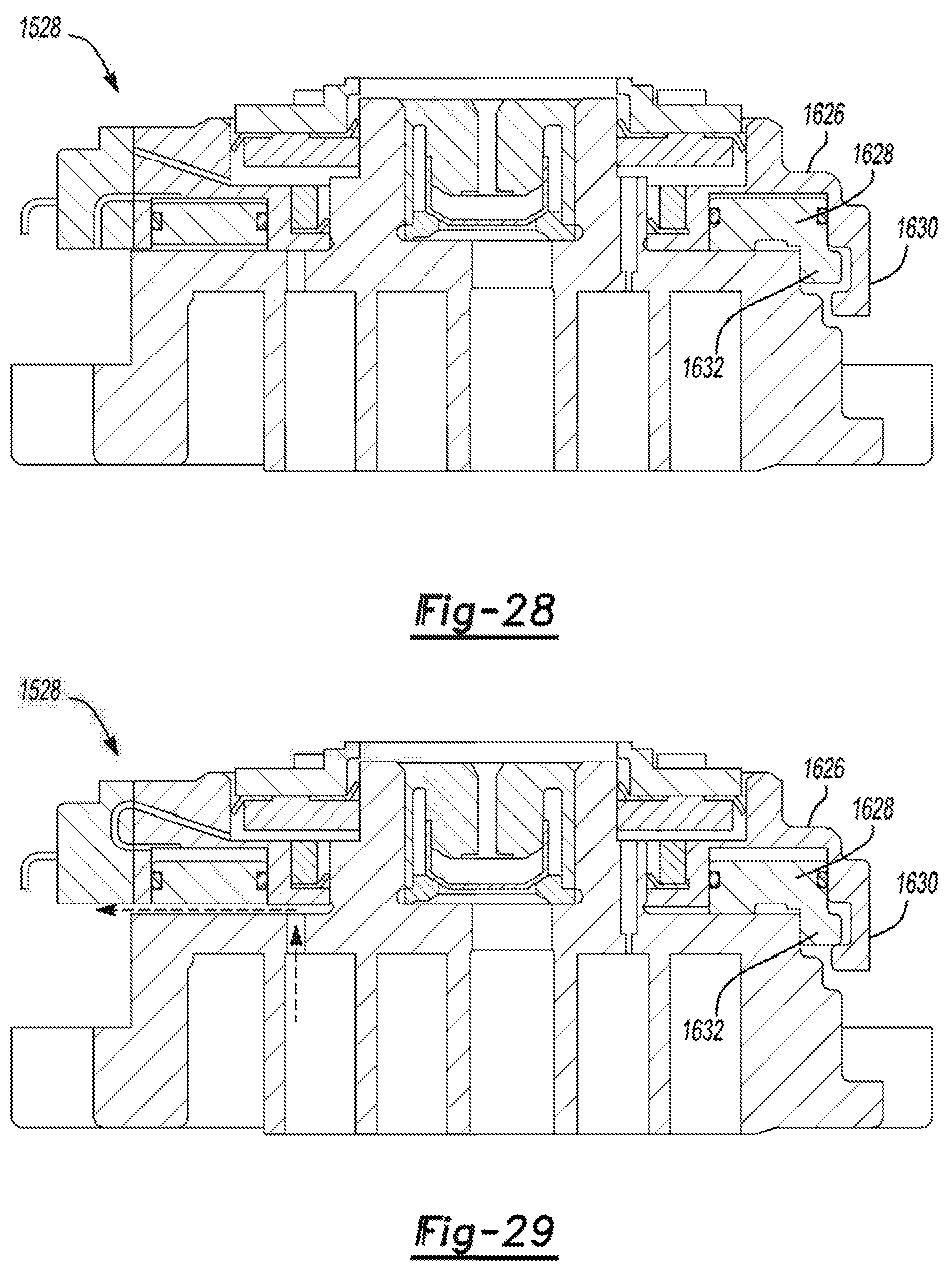
D00017

XML
uspto.report is an independent third-party trademark research tool that is not affiliated, endorsed, or sponsored by the United States Patent and Trademark Office (USPTO) or any other governmental organization. The information provided by uspto.report is based on publicly available data at the time of writing and is intended for informational purposes only.
While we strive to provide accurate and up-to-date information, we do not guarantee the accuracy, completeness, reliability, or suitability of the information displayed on this site. The use of this site is at your own risk. Any reliance you place on such information is therefore strictly at your own risk.
All official trademark data, including owner information, should be verified by visiting the official USPTO website at www.uspto.gov. This site is not intended to replace professional legal advice and should not be used as a substitute for consulting with a legal professional who is knowledgeable about trademark law.