Cutting burr shank configuration
del Rio , et al. March 23, 2
U.S. patent number 10,952,747 [Application Number 16/222,446] was granted by the patent office on 2021-03-23 for cutting burr shank configuration. This patent grant is currently assigned to DePuy Synthes Products, Inc.. The grantee listed for this patent is DePuy Synthes Products, Inc.. Invention is credited to Eddy H. del Rio, Duane Jeffrey Enck.


| United States Patent | 10,952,747 |
| del Rio , et al. | March 23, 2021 |
Cutting burr shank configuration
Abstract
A cutting burr that includes a pair of axially spaced diamond-shaped portions designed to be keyed into a spindle of a locking mechanism of a high speed surgical drilling instrument and adapted to fit into a single pawl thereof to lock said cutting burr in place so as to prevent axial movement thereof and provide concentric rotation of said cutting burr without any wobbling. The orientation of both portions may be identical with respect to a center plan and diamond shape in the portion at the proximal end of the shank of the cutting tool may be larger than the intermediately located diamond shape of the other portion. The apexes of the facets of the six-sided diamond shape may be disposed below the surface of the shank of the cutting burr.
| Inventors: | del Rio; Eddy H. (West Palm Beach, FL), Enck; Duane Jeffrey (West Palm Beach, FL) | ||||||||||
|---|---|---|---|---|---|---|---|---|---|---|---|
| Applicant: |
|
||||||||||
| Assignee: | DePuy Synthes Products, Inc.
(Raynham, MA) |
||||||||||
| Family ID: | 1000005436996 | ||||||||||
| Appl. No.: | 16/222,446 | ||||||||||
| Filed: | December 17, 2018 |
Prior Publication Data
| Document Identifier | Publication Date | |
|---|---|---|
| US 20190223888 A1 | Jul 25, 2019 | |
Related U.S. Patent Documents
| Application Number | Filing Date | Patent Number | Issue Date | ||
|---|---|---|---|---|---|
| 15818314 | Nov 20, 2017 | 10154849 | |||
| 15225043 | Nov 21, 2017 | 9820756 | |||
| 14223011 | Aug 2, 2016 | 9402638 | |||
| 13082016 | Apr 8, 2014 | 8690876 | |||
| Current U.S. Class: | 1/1 |
| Current CPC Class: | A61B 17/1617 (20130101); A61B 17/162 (20130101); Y10T 408/907 (20150115) |
| Current International Class: | A61B 17/16 (20060101) |
| Field of Search: | ;606/79-81,84,85,167,169-171,180 ;81/177.85,438 ;279/35,37,77,78,89,106,107,131,156 ;403/383 ;408/226 |
References Cited [Referenced By]
U.S. Patent Documents
| 170604 | November 1875 | Williams |
| 170694 | December 1875 | Williams |
| RE8360 | August 1878 | Williams |
| 233707 | October 1880 | Starr |
| 233709 | October 1880 | Starr |
| 269627 | December 1882 | Bonner |
| 283745 | August 1883 | Bartlett |
| 287683 | October 1883 | Johnston et al. |
| 302870 | July 1884 | Starr |
| 327558 | October 1885 | Kuder |
| 359798 | March 1887 | Mann |
| 415983 | November 1889 | Starr |
| 418108 | December 1889 | Browne |
| 474011 | May 1892 | Harrison |
| 553226 | January 1896 | Brockett |
| 748398 | December 1903 | Middleton |
| 988154 | March 1911 | Thiemer |
| 988903 | April 1911 | Smith |
| 1135057 | April 1915 | Schultis |
| 1188533 | June 1916 | Cobey |
| 1433590 | October 1922 | Ziegler |
| 1503962 | August 1924 | Milliken |
| 1578397 | March 1926 | Cone |
| 1717663 | June 1929 | Checkley |
| 1726012 | August 1929 | Bilz |
| 1862337 | June 1932 | Emrick |
| 1947957 | February 1934 | Tiliman |
| 2012280 | August 1935 | Johansen |
| 2101347 | December 1937 | Robinette |
| 2367863 | January 1945 | Grey |
| 2390950 | December 1945 | Lanfranconi |
| 2405018 | July 1946 | Crowley |
| 2448817 | September 1948 | McArthur |
| 2473380 | June 1949 | Ljunggren |
| 2494166 | January 1950 | Drissner |
| 2543290 | February 1951 | Johansson |
| 2614781 | October 1952 | Engel |
| 2686682 | August 1954 | Csaki |
| 2740974 | April 1956 | Lazarus |
| 2769643 | November 1956 | Berthold |
| 2787010 | April 1957 | Uphoff |
| 2874985 | February 1959 | March |
| 2939643 | June 1960 | Barsam, Jr. |
| 2955831 | October 1960 | Zandberg |
| 3046029 | July 1962 | Weber et al. |
| 3054308 | September 1962 | Larry |
| 3084898 | April 1963 | Miller |
| 3136347 | June 1964 | Linquist |
| RE25804 | June 1965 | Misuraca |
| 3252667 | May 1966 | Miller |
| 3466971 | September 1969 | Meyer |
| 3533638 | October 1970 | Sedgwick |
| 3574374 | April 1971 | Keller |
| 3589826 | June 1971 | Fenn |
| 3596917 | August 1971 | Meyer |
| 3599996 | August 1971 | Holt |
| 4032163 | June 1977 | Holt |
| 4055185 | October 1977 | Waldron |
| 4073497 | February 1978 | Flagg |
| 4114276 | September 1978 | Malata |
| 4115024 | September 1978 | Sussmuth |
| 4131165 | December 1978 | Wanner |
| 4298074 | November 1981 | Mattchen |
| 4303252 | December 1981 | Snider |
| 4325661 | April 1982 | Tickins |
| 4374481 | February 1983 | Brodie |
| 4565472 | January 1986 | Brennsteiner |
| 4632195 | December 1986 | Emmerich |
| 4710075 | December 1987 | Davison |
| 4984667 | January 1991 | Tjaden |
| 5037251 | August 1991 | Roth |
| 5074025 | December 1991 | Willard |
| 5152642 | October 1992 | Pitts et al. |
| 5218890 | June 1993 | Christ, Jr. |
| 5271697 | December 1993 | Johnson |
| 5421682 | June 1995 | Obermeier |
| 5433562 | July 1995 | Phillips |
| 5466101 | November 1995 | Meyen |
| 5542846 | August 1996 | Quinn |
| 5601560 | February 1997 | Del Rio |
| 5630818 | May 1997 | Del Rio |
| 5658305 | August 1997 | Baker |
| 5664792 | September 1997 | Tseng |
| 5735535 | April 1998 | McCombs |
| 5741263 | April 1998 | Umber |
| 5820136 | October 1998 | Han |
| 5833246 | November 1998 | Trott |
| 5833704 | November 1998 | McCombs et al. |
| 5888200 | March 1999 | Walen |
| 5904687 | May 1999 | Del Rio |
| 5921563 | July 1999 | Huggins |
| 5941891 | August 1999 | Walen |
| 5957634 | September 1999 | Carpinetti |
| 6033408 | March 2000 | Gage |
| 6045564 | April 2000 | Walen |
| 6129363 | October 2000 | Mack |
| 6135461 | October 2000 | Below et al. |
| RE37358 | September 2001 | Del Rio |
| 6302408 | October 2001 | Zierpka |
| 6341926 | January 2002 | Liu |
| 6409181 | June 2002 | Hsueh |
| 6533235 | March 2003 | Dymerski |
| 6533291 | March 2003 | Huggins |
| 6572311 | June 2003 | Vasudeva |
| 6607533 | August 2003 | Del Rio |
| 6623220 | September 2003 | Nuss et al. |
| 6705807 | March 2004 | Rudolph |
| 6725749 | April 2004 | Liou |
| 6733218 | May 2004 | Del Rio |
| 6769846 | August 2004 | Campbell, Jr. et al. |
| 6780189 | August 2004 | Tidwell |
| 7011661 | March 2006 | Riedel |
| 7028589 | April 2006 | Cheng |
| 7066940 | June 2006 | Riedel |
| 7114728 | October 2006 | Chen |
| 7140817 | November 2006 | Phillips |
| 7207400 | April 2007 | Bise |
| 7258349 | August 2007 | Frauhammer |
| 7316529 | January 2008 | Phillips |
| 7367762 | May 2008 | Takase et al. |
| 7465309 | December 2008 | Walen |
| 7712746 | May 2010 | Manschitz |
| 7845428 | December 2010 | Sakamaki |
| 8273097 | September 2012 | Malla |
| 8403338 | March 2013 | Hangleiter |
| 8690876 | April 2014 | del Rio |
| 8801713 | August 2014 | del Rio |
| 9113917 | August 2015 | del Rio |
| 9381023 | July 2016 | del Rio et al. |
| 9402638 | August 2016 | del Rio |
| 9681879 | June 2017 | del Rio et al. |
| 9820756 | November 2017 | del Rio et al. |
| 10154849 | December 2018 | del Rio et al. |
| 10194921 | February 2019 | del Rio et al. |
| 2001/0006280 | July 2001 | Hangleiter |
| 2001/0042964 | November 2001 | Bedi |
| 2002/0009341 | January 2002 | Vasudeva |
| 2002/0058958 | May 2002 | Walen |
| 2002/0151902 | October 2002 | Riedel |
| 2002/0159850 | October 2002 | Ravid |
| 2002/0165549 | November 2002 | Owusu-Akyaw |
| 2003/0060829 | March 2003 | Del Rio |
| 2003/0060841 | March 2003 | Del Rio |
| 2003/0130663 | July 2003 | Walen |
| 2003/0163134 | August 2003 | Riedel |
| 2005/0096661 | May 2005 | Farrow |
| 2006/0049587 | March 2006 | Cornwell |
| 2006/0053974 | March 2006 | Blust et al. |
| 2008/0119863 | May 2008 | Mellier |
| 2008/0208195 | August 2008 | Shores et al. |
| 2008/0208229 | August 2008 | Tidwell |
| 2009/0146421 | June 2009 | Engdahl |
| 2009/0273146 | November 2009 | Dezheng |
| 2009/0326540 | December 2009 | Estes |
| 2010/0063524 | March 2010 | McCombs |
| 2010/0219594 | September 2010 | Nash |
| 2012/0003057 | January 2012 | Leyba |
| 2012/0259336 | October 2012 | del Rio |
| 2012/0259337 | October 2012 | del Rio |
| 2012/0275875 | November 2012 | Gischus |
| 2013/0130663 | May 2013 | Jung et al. |
| 2015/0032111 | January 2015 | del Rio |
| 2019/0223888 | July 2019 | del Rio |
| 2631675 | Mar 2003 | CN | |||
| 1406700 | Apr 2003 | CN | |||
| 1672641 | Sep 2005 | CN | |||
| 2774405 | Apr 2006 | CN | |||
| 2882550 | Mar 2007 | CN | |||
| 101365390 | Feb 2009 | CN | |||
| 02009507 | Jan 1990 | JP | |||
| 02009507 | Jan 1990 | JP | |||
| 03019703 | Jan 1991 | JP | |||
| 03019703 | Jan 1991 | JP | |||
| 07214406 | Aug 1995 | JP | |||
| 07214406 | Aug 1995 | JP | |||
| 2000/052114 | Feb 2000 | JP | |||
| 2000052114 | Feb 2000 | JP | |||
| 2002/137111 | May 2002 | JP | |||
| 2002137111 | May 2002 | JP | |||
| 2011/136530 | Jul 2011 | JP | |||
| 1996/010962 | Apr 1996 | WO | |||
| 2004/082490 | Sep 2004 | WO | |||
| 2008/020828 | Feb 2008 | WO | |||
| WO-2008020828 | Feb 2008 | WO | |||
| 2012/138338 | Oct 2012 | WO | |||
Other References
|
Office Action, dated Dec. 16, 2014, received in connection with JP Patent Application No. 2014503639. (English Translation). cited by applicant . International Preliminary Report on Patentability and Written Opinion, dated Oct. 8, 2013, received in connection with corresponding International Patent Application No. PCT/US2011/031505. cited by applicant . International Search Report, dated Feb. 28, 2012, received in connection with corresponding International Patent Application No. PCT/US2011/031505. cited by applicant . International Preliminary Report on Patentability and Written Opinion, dated Oct. 8, 2013, received in connection with related International Patent Application No. PCT/US2011/031512. cited by applicant . International Search Report, dated Jan. 4, 2012, received in connection with related International Patent Application No. PCT/US2011/031512. cited by applicant. |
Primary Examiner: Gibson; Eric S
Attorney, Agent or Firm: Meunier Carlin & Curfman LLC
Parent Case Text
CROSS-REFERENCE TO RELATED APPLICATIONS
The subject matter described in this application is related to subject matter disclosed in the following commonly assigned applications: U.S. patent application Ser. No. 15/818,314 filed Nov. 20, 2017, which is a continuation of U.S. patent application Ser. No. 15/225,043 (now U.S. Pat. No. 9,820,756) filed Aug. 1, 2016, which is a continuation of U.S. patent application Ser. No. 14/223,011 (now U.S. Pat. No. 9,402,638) filed Mar. 24, 2014, which is a continuation of U.S. patent application Ser. No. 13/082,016 (now U.S. Pat. No. 8,690,876), filed on Apr. 7, 2011, entitled "CUTTING BURR SHANK CONFIGURATION," which are incorporated herein by reference in their entirety.
Claims
What is claimed:
1. A cutting burr comprising: a shank with an engagement feature at a proximal end of the shank sized and configured to receive rotational forces from a surgical drilling instrument and a cutting bit formed on a distal end of the shank, the engagement feature including four planar surfaces, where a first pair of the planar surfaces includes a first surface and a second surface that meet at a first apex, where a second pair of the planar surfaces includes a third surface and a fourth surface that meet at a second apex, where the first and the third surfaces are opposite and parallel each other and the second and the fourth surfaces are opposite and parallel each other, and an insert including a slot defined by substantially parallel opposing side walls and curved side walls extending between the parallel opposing side walls, where the engagement feature is received within the slot and a width of the slot measured between the opposing side walls corresponds to a width between the first surface and the third surface of the engagement feature such that shank cannot rotate within the slot when the shank is coupled to the insert.
2. The cutting burr of claim 1, wherein the insert is adapted to be inserted into a complementary shaped mating recess of a surgical drilling instrument, wherein engagement between the opposing side walls of the insert and the corresponding first or second pair of planar sides of the engagement feature provides rotational forces to the shank.
3. The cutting burr of claim 1, wherein a radius of curvature of the curved side walls corresponds to a radius of curvature of an outer wall of the insert.
4. The cutting burr of claim 1, wherein the first pair of the planar surfaces of the engagement feature is joined to the second pair of the planar surfaces by curved side edges, the first and fourth surfaces being joined by a first curved side edge and the second and third surfaces being joined by a second curved side edge, wherein the radius of curvature of the curved side walls of the slot corresponds to a radius of curvature of the first and second curved side edges of the engagement feature.
5. The cutting burr of claim 4, wherein a diameter of the slot defined at the curved side walls corresponds to a diameter defined between the first and second curved side edges of the engagement feature.
6. The cutting burr of claim 1, wherein the slot defines a diamond-shape in cross-section and is sized and configured to engage the first and second pairs of planar surfaces of the engagement feature.
7. The cutting burr of claim 1, wherein the insert further defines a pointed-shaped inlet end, where the inlet end facilitates an alignment and insertion of the cutting burr as it is advanced toward and into the slot, wherein, during coupling, contact between the proximal end of the shank and the pointed-shaped inlet end of the insert causes the shank to rotate thereby bringing the engagement feature into alignment with the slot.
8. The cutting burr of claim 7, wherein the pointed-shaped inlet end includes a first tapered surface extending from an outer surface of the insert towards a centerline of the insert and a second tapered surface extending from the outer surface of the insert towards the centerline of the insert opposite the first tapered surface.
9. The cutting burr of claim 1, wherein the insert includes a hole extending through a sidewall of the insert, where a dowel pin received within the hole locates the cutting burr and the engagement feature within the slot.
10. The cutting burr of claim 1, wherein the first and the third surfaces of the engagement feature have equal length measured around the circumference of the shank, wherein the second and fourth surfaces of the engagement feature have an equal length from the second length measured around a circumference of the shank.
11. The cutting burr of claim 1, wherein the width of the engagement feature measured between the first apex and the second apex is less than a diameter of the shank.
12. The cutting burr of claim 1, wherein the first apex and the second apex are in axial alignment.
13. The cutting burr of claim 1, wherein the engagement feature extends from the proximal end of the shank to a tapered surface extending from each of the four planar surfaces to an outer surface of the shank.
14. The cutting burr of claim 1, wherein the first pair of the planar surfaces is joined to the second pair of the planar surfaces around a circumference of the shank by curved side edges, the first and fourth surfaces being joined by a first curved side edge and the second and third surfaces being joined by a second curved side edge, and wherein the curved side edges have a radius of curvature corresponding to an outermost radius of curvature of the shank.
15. A surgical instrument including: a surgical drilling instrument including a motor and a locking pawl; a cutting burr releasably connected to the locking pawl and receiving rotational forces output from the motor, the cutting burr comprising: a shank with an engagement feature at a proximal end of the shank sized and configured to receive rotational forces from the surgical instrument and a cutting bit formed on a distal end of the shank, the engagement feature including four planar surfaces, where a first pair of the planar surfaces includes a first surface and a second surface that meet at a first apex, where a second pair of the planar surfaces includes a third surface and a fourth surface that meet at a second apex, where the first and the third surfaces are opposite and parallel each other and the second and the fourth surfaces are opposite and parallel each other, and an insert including a slot defined by substantially parallel opposing side walls and curved side walls extending between the parallel opposing side walls, where the engagement feature is received within the slot and a width of the slot measured between the opposing side walls corresponds to a width between the first surface and the third surface of the engagement feature such that shank cannot rotate within the slot when the shank is coupled to the insert.
16. The surgical instrument of claim 15, wherein the four planar surfaces of the engagement feature are adapted to accept rotational engagement forces of the motor, wherein the locking pawl engages the cutting burr to fix an axial position of the cutting burr with respect to the surgical drilling instrument.
17. The surgical instrument of claim 15, wherein the first pair of the planar surfaces of the engagement feature is joined to the second pair of the planar surfaces by curved side edges, the first and fourth surfaces being joined by a first curved side edge and the second and third surfaces being joined by a second curved side edge, wherein a radius of curvature of the curved side walls of the slot corresponding to a radius of curvature of the first and second curved side edges of the engagement feature.
18. The surgical instrument of claim 15, wherein the slot defines a diamond-shaped slot sized and configured to engage the first and second pairs of planar surfaces of the engagement feature.
19. The surgical instrument of claim 15, wherein the insert further defines a pointed-shaped inlet end, and wherein the inlet end facilitates an alignment and insertion of the cutting burr as it is advanced toward and into the slot, wherein, during coupling, contact between the proximal end of the shank and the pointed-shaped inlet end of the insert causes the shank to rotate thereby bringing the engagement feature into alignment with the keyed slot, wherein the pointed-shaped inlet end includes a first tapered surface extending from an outer surface of the insert towards a centerline of the insert and a second tapered surface extending from the outer surface of the insert towards a centerline of the insert opposite the first tapered surface.
Description
BACKGROUND
When performing surgery, surgeons may utilize a surgical drilling instrument for drilling, cutting or shaping bones that utilize a numerous different kinds and sizes of cutting burrs and attachments. During certain medical operations, the cutting burr needs to be changed. The change must be done timely and efficiently in view of the surgical demands. To this end, the portion of the cutting burr, namely, the proximate end of the shank typically lacks a configuration to accommodate this change of the cutting burr.
SUMMARY
Disclosed herein is a cutting burr that provides for a quick release that is fast and simple, and which facilitates the insertion of the cutting burr into a surgical drilling instrument. The cutting burr may have a pair of axially spaced six sided diamond-shaped portions, where one diamond-shaped portion may be formed at an edge of the proximal end of the cutting burr and provides a positive connection with a drive spindle that is connected to a drive motor of the surgical drilling instrument. A second, axially disposed diamond-shaped portion is adapted to mate with a locking pawl of the surgical drilling instrument. The locking pawl engages the axially disposed diamond-shaped portion to lock the cutting burr into the surgical drilling instrument with substantially no axial movement.
In some implementations, a detent pawl is provided to hold the cutting burr within the surgical instrument when it is in a loading position. The detent pawl may engage the axially disposed diamond-shaped portion at a side opposite the locking pawl.
In some implementations, the diamond-shaped portion at the proximal end is sized such that it can be used with older surgical drilling instruments that may not be provided with a complementary receiving recess for the diamond-shaped portion.
This summary is provided to introduce a selection of concepts in a simplified form that are further described below in the detailed description. This summary is not intended to identify key features or essential features of the claimed subject matter, nor is it intended to be used to limit the scope of the claimed subject matter.
BRIEF DESCRIPTION OF THE DRAWINGS
The foregoing summary is better understood when read in conjunction with the appended drawings. For the purposes of illustration, there is shown in the drawings exemplary implementations; however, these implementations are not limited to the specific methods and instrumentalities disclosed. In the drawings:
FIG. 1 a fragmentary top plan view illustrating the axially spaced six-sided diamond-shaped cut out portion or portions formed on the proximate end of the shank of the cutting burr;
FIG. 2 is a perspective view of FIG. 1;
FIG. 3 is another prospective view of FIG. 1 slightly turned illustrating one of the facets in each of the six-sided diamond-shaped portions;
FIG. 4 is another perspective view of FIG. 2 slightly turned illustrating the top facets of the six-sided diamond-shaped portions;
FIG. 5 is an end view taken along lines 5-5 of FIG. 3 illustrating the shape of the six-sided diamond-shaped portion formed in the cutting burr shank;
FIG. 6 is a sectional view taken along lines 6-6 of FIG. 4 illustrating the shape of the six-sided diamond-shaped portion and illustrating the different sizes and the orientation of the six-sided diamond portion formed in the cutting burr shank;
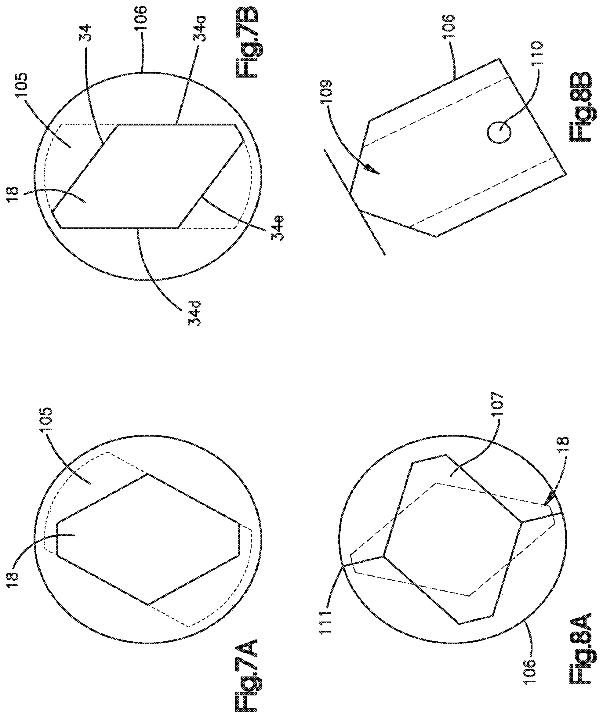
FIGS. 7A and 7B illustrate a backwards compatibility of the cutting burr of FIGS. 1-6 within a receiving portion of conventional surgical drill;
FIGS. 8A and 8B illustrate a self-alignment aspect of the diamond-shaped portion at a proximal end of the cutting burr in relation to a keyed slot of a surgical drill;
FIG. 9 is an elevated view of the cutting burr with a spherical shaped cutting bit illustrating the diamond-shaped portions formed in the shank thereof;
FIG. 10 is another elevated view of an example cutting burr; and
FIG. 11 is another elevated view of an example cutting burr.
DETAILED DESCRIPTION
As used herein, the term "cutting burr" may be analogous with terms such as bit, drill bit, surgical drill bit and the like. The term "attachment" may have several meanings within the text of this application, but when generalized as a component of a surgical drilling instrument it refers to a portion of the instrument that attaches to the end of the motor/locking mechanism and receives the cutting burr. An "attachment" may be a controlled depth attachment, a minimally invasive attachment and the like. The surgical drilling instrument may include an integral motor (electric or pneumatic) and a locking mechanism and an attachment releasably connected to the locking mechanism.
High speed surgical drills are increasingly being used by surgeons when performing delicate bone dissection in areas such as the cervical and lumbar spine. Such surgical drills operate at very high R.P.M., and are able to rotationally drive multiple types of attachments and cutting burrs. As will be described below, a cutting burr of the present disclosure includes a shank that defines two substantially diamond-shaped portions. The substantially diamond-shaped portions provide for ease of insertion and removal of the cutting burr to and from a compatible surgical drill. The substantially diamond-shaped portions also enable the surgical drill to direct higher levels of torque to the cutting burr during surgical procedures.
Referring to FIGS. 1-6, the cutting burr is generally illustrated by reference numeral 10. The attachment portion 12 of the shank 16 of the cutting burr 10 is generally shown as reference numeral 12. A proximal end 14 of the shank 16 is formed with a pair of axially spaced six-sided diamond-shaped portions 18 and 20. As shown in FIGS. 4 and 5, an upper surface of portion 18 includes an apex 32 and a pair of facets 34 and 34a also fairing to side edges 34b and 34c. The side edges 34b and 34c may be curved to match the radius of curvature of an outer surface of the shank 16. As shown in FIGS. 4 and 6, an upper surface 24 of the portion 20 includes apex 26 and a pair of facets 30 and 30a fairing from the apex 26 to the side edges 30b and 30c. The side edges 30b and 30c may be curved to match the radius of curvature of an outer surface of the shank 16.
As shown in the Figs. the diametrical dimensions of the vertices in both portions is less than the diameter of the main body of the shank. The shank 16 may include an annular groove 29. The lower surfaces of the pair of six-sided diamond portions 18 and 20 are a mirror image of the upper surface. While the diamond-shaped portions 18 and 20 are described as being "diamond-shaped," it is noted that such terminology is intended to encompass any six-sided (hexagon) shape having a cross-section with flat edges that meet at a six vertices, curved edges that meet at six points, or some combination of both to form the six sides. The flat and curved edges, and combinations thereof, may be applied to other polygon shapes having different numbers of sides.
The diamond-shaped portion 18 at the outermost proximal end is designed to be inserted into a mating drive portion of a surgical drill, as will be described with reference to FIGS. 8A and 8B. The diamond-shaped portion 20 is provided as an abutment surface of a retractable locking pawl of the surgical drill to provide axial locking of the shank 16 within the surgical drill. The locking pawl may axially abut the adjacent abutment surface of the diamond-shaped portion 20 to axially lock the cutting burr 10 in place, thus providing substantially zero axial movement. For example, an engagement portion of locking pawl may be contoured having a generally V-shape with inner surfaces that fit against the facets 30 and 30a of the diamond-shaped portion 20.
As shown in FIG. 3, a back wall 42 may be formed perpendicular with relation to the central line A and faces a front wall 40 that is tapered from the facet (e.g., 30a) to the outside diameter of the shank 16. In accordance with some aspects, an engagement face of the locking pawl may abut against the back wall 42 to provide axial locking of the cutting burr 10 within the surgical drill. A tapered front wall 40 may facilitate the engagement of the locking pawl into the diamond-shaped portion 20.
The diamond-shaped portion 20 may also be engaged by a detent pawl of the surgical drill. For example, an engagement end of detent pawl may be contoured, e.g., having a generally hill shape to partially fit into the diamond-shaped portion 20 on an opposite side of the engagement end of the locking pawl. The detent pawl may be provided to apply a sufficient force on the diamond-shaped portion 20 to allow the cutting burr 10 to be moved in and out of the surgical drill, while reducing the likelihood that the cutting burr will inadvertently fall out of the surgical drill when in a loading position.
As shown by the a comparison of the sectional views of the diamond-shaped portions 18 and 20 (FIGS. 5 and 6), the two diamond shapes may be different in size, where the diamond shape in diamond-shaped portion 18 is larger than the diamond shape of the diamond-shaped portion 20. As illustrated, the vertices 32 and 36 fall below the outer diameter of the shank 16 and both diamond shapes are in axial alignment with each other and may be oriented in parallel relationship. In some implementations, the diamond-shaped portion 20 and the diamond-shaped portion 18 may be the same size, or the diamond-shaped portion 18 may be larger than the diamond-shaped portion 20. In the various configurations, the vertices 26 and 32 of diamond-shaped portions 20 and 18, respectively, are along a same line and in a same plane as the center line A. Exemplary dimensions of the six-sided diamond diamond-shaped portions 18 and 20 are listed in degrees (.degree.) and inches ('') and may be substantially as follows:
The angle of the facets of the six-sided diamond in the diamond-shaped portion 20-a=47.degree.;
The width of the facets of the six-sided diamond in the diamond-shaped portion 20-b=0.046'';
The width of the facets of the six-sided diamond in the diamond-shaped portion 18-c=0.065'';
The width of the shank 16 at the space between diamond-shaped portions 18 and 20-d=0.029'';
The length of the diamond-shaped portion 20-e=0.068''; and
The length between the proximal end and the back wall of diamond-shaped portion 18 f=0.149''. This dimension may contribute to the feature of substantially reducing the axial play of the cutting burr.
Thus, in accordance with the above, the diamond-shaped portions 18 and 20 provide sufficient cross-sectional dimensions to meet strength and reliability requirements needed for high-speed, large force surgical applications. Facets 34 and 34a of the diamond shape 18 provide positive engagement surfaces in both clockwise and counter-clockwise rotational directions and are sufficiently sized to withstand rotations forces in either direction without wobbling within the surgical drill. For example, some surgical drills provide bi-directional rotation, allowing the surgeon to selectively reverse rotation for various surgical techniques. In conventional designs, there may be rotational play between a bit end and a drive portion. However, the symmetrical diamond facets 34 and 34a of the diamond-shaped portion 18 provide substantial drive surfaces in either direction.
With reference to FIGS. 7A and 7B, the diamond-shaped portion 18 at the outermost proximal end of the cutting burr 10 is designed to have unidirectional backward compatibility with older drill instruments in accordance with aspects of the disclosure. For example, a conventional drill instrument may include an insert 106 that defines a generally rectangular slot 105 having rounded side walls. The rounded side walls may be shaped with a radius of curvature that parallels the outer wall of the insert 106. Conventional cutting burrs may include a complementary generally rectangular portion having rounded side walls that is received by the slot 105. The insert 106 may be driven by a motor, thus providing rotational force on the cutting burr.
As shown in FIG. 7A, in accordance with some implementations, facets 34a and 34d of the diamond-shaped portion 18 engage the inner walls of the slot 105. The dimension c of the diamond-shaped portion 18, noted above, may be sized such that the surface area of the facets 34a and 34d is substantial enough to withstand the torque provided by the motor of the conventional drill instrument. Thus, the cutting burr 10 of the present disclosure may be utilized by conventional drill instruments.
Referring now to FIGS. 8A and 8B, in some implementations, the cutting burr 10 of the present disclosure provides for a level of self-alignment within the insert 106. The insert 106 may be provided in a compatible surgical drill and define a diamond-shaped key slot 107, a pointed shaped inlet end 109, and opposing holes 110 that formed in the insert 106 for receiving dowel pin which may serve to locate the cutting burr 10 when inserted into the key slot 107. The inlet end 109 serves to facilitate the alignment and insertion of the cutting burr 10 as it is advanced toward and into the key slot 107 of the insert 106. For example, if the diamond-shaped portion 18 is not in alignment with the key slot 107 (FIG. 8A), a bottom surface of the diamond-shaped portion 18 will contact an apex 111 of the inlet end 109 causing the cutting burr 10 to rotate into alignment with the key slot 107. As such, the cooperative engagement of the diamond-shaped portion 18 and inlet end 109 facilitates the easy insertion of the cutting burr 10 into the compatible surgical drill. As such, the diamond portion 18 serves to provide a secure connection in the key slot 107.
FIGS. 9, 10, and 11 illustrate different example cutting bits 22 provided at a distal end on the shank 16. As described above, the shank 16 may include the attachment portion 12. The cutting bits 22 may be milled or cut-out portions. The cutting burr 10 in FIG. 9 exemplifies a fluted ball or drill bit; the cutting burr 10 in FIG. 10 exemplifies a diamond ball; and the cutting burr 10 in FIG. 11 exemplifies a twist drill. The cutting bits 22 are presented only as examples and are not intended to limit the scope of the present disclosure as numerous variations are possible.
Thus, as described above, a cutting burr is provided with an attachment end that has a configuration and dimensions that serve to facilitate the insertion of the cutting burr into the surgical cutting instrument. When locked in the running position there is a structure that prevents the cutting burr from having any axial movement. Also, there is a positive connection such that the cutting burr rotates concentrically without any wobbling motion.
While particular aspects of the present subject matter described herein have been shown and described, it will be apparent to those skilled in the art that, based on the teachings herein, changes and modifications may be made without departing from the subject matter described herein and its broader aspects and, therefore, the appended claims are to encompass within their scope all such changes and modifications as are within the true spirit and scope of the subject matter described herein.
* * * * *
D00000
D00001
D00002
D00003
XML
uspto.report is an independent third-party trademark research tool that is not affiliated, endorsed, or sponsored by the United States Patent and Trademark Office (USPTO) or any other governmental organization. The information provided by uspto.report is based on publicly available data at the time of writing and is intended for informational purposes only.
While we strive to provide accurate and up-to-date information, we do not guarantee the accuracy, completeness, reliability, or suitability of the information displayed on this site. The use of this site is at your own risk. Any reliance you place on such information is therefore strictly at your own risk.
All official trademark data, including owner information, should be verified by visiting the official USPTO website at www.uspto.gov. This site is not intended to replace professional legal advice and should not be used as a substitute for consulting with a legal professional who is knowledgeable about trademark law.