Camera optical lens
Fang , et al. March 16, 2
U.S. patent number 10,948,691 [Application Number 15/982,195] was granted by the patent office on 2021-03-16 for camera optical lens. This patent grant is currently assigned to AAC Optics Solutions Pte. Ltd.. The grantee listed for this patent is AAC Technologies Pte. Ltd.. Invention is credited to Yuanshan Cui, Chunhuan Fang, Yanmei Wang, Lei Zhang.


| United States Patent | 10,948,691 |
| Fang , et al. | March 16, 2021 |
Camera optical lens
Abstract
The present disclosure discloses a camera optical lens. The camera optical lens including, in an order from an object side to an image side, a first lens, a second lens having a positive refractive power, a third lens having a positive refractive power, a fourth lens, a fifth lens, and a sixth lens. The first lens is made of plastic material, the second lens is made of plastic material, the third lens is made of plastic material, the fourth lens is made of plastic material, the fifth lens is made of glass material, and the sixth lens is made of plastic material. The camera optical lens further satisfies specific conditions.
| Inventors: | Fang; Chunhuan (Shenzhen, CN), Zhang; Lei (Shenzhen, CN), Wang; Yanmei (Shenzhen, CN), Cui; Yuanshan (Shenzhen, CN) | ||||||||||
|---|---|---|---|---|---|---|---|---|---|---|---|
| Applicant: |
|
||||||||||
| Assignee: | AAC Optics Solutions Pte. Ltd.
(Singapore, SG) |
||||||||||
| Family ID: | 1000005424622 | ||||||||||
| Appl. No.: | 15/982,195 | ||||||||||
| Filed: | May 17, 2018 |
Prior Publication Data
| Document Identifier | Publication Date | |
|---|---|---|
| US 20190285839 A1 | Sep 19, 2019 | |
Foreign Application Priority Data
| Mar 13, 2018 [CN] | 201810203693.2 | |||
| Mar 13, 2018 [CN] | 201810203738.6 | |||
| Current U.S. Class: | 1/1 |
| Current CPC Class: | G02B 9/62 (20130101); G02B 13/0045 (20130101); G02B 27/0037 (20130101) |
| Current International Class: | G02B 9/62 (20060101); G02B 27/00 (20060101); G02B 13/00 (20060101) |
References Cited [Referenced By]
U.S. Patent Documents
| 8964096 | February 2015 | Katou |
Assistant Examiner: Patel; Vipin
Attorney, Agent or Firm: IPro, PLLC Xu; Na
Claims
What is claimed is:
1. A camera optical lens comprising, from an object side to an image side in sequence: a first lens, a second lens having a positive refractive power, a third lens having a positive refractive power, a fourth lens, a fifth lens, and a sixth lens; wherein the camera optical lens further satisfies the following conditions: 0.5.ltoreq.f1/f.ltoreq.10; 1.7.ltoreq.n5.ltoreq.2.2; 0.01.ltoreq.d9/TTL.ltoreq.0.2; 0.57.ltoreq.f12/f.ltoreq.1.96; where f: the focal length of the camera optical lens; f1: the focal length of the first lens; f12: the combined focal length of the first lens and the second lens; n5: the refractive index of the fifth lens; d9: the thickness on-axis of the fifth lens; TTL: the total optical length of the camera optical lens.
2. The camera optical lens as described in claim 1, wherein the first lens is made of plastic material, the second lens is made of plastic material, the third lens is made of plastic material, the fourth lens is made of plastic material, the fifth lens is made of glass material, the sixth lens is made of plastic material.
3. The camera optical lens as described in claim 1 further satisfying the following conditions: 1.125.ltoreq.f1/f.ltoreq.7.995; 1.704.ltoreq.n5.ltoreq.2.1; 0.027.ltoreq.d9/TTL.ltoreq.0.132.
4. The camera optical lens as described in claim 1, wherein first lens has a positive refractive power with a convex object side surface and a concave image side surface to the proximal axis, the camera optical lens further satisfies the following conditions: -30.87(R1+R2)/(R1-R2).ltoreq.-3.57; 0.13 mm.ltoreq.d1.ltoreq.0.62 mm; where R1: the curvature radius of object side surface of the first lens; R2: the curvature radius of image side surface of the first lens; d1: the thickness on-axis of the first lens.
5. The camera optical lens as described in claim 4 further satisfying the following conditions: -19.29.ltoreq.(R1+R2)/(R1-R2).ltoreq.-4.47; 0.21 mm.ltoreq.d1.ltoreq.0.5 mm.
6. The camera optical lens as described in claim 1, wherein the second lens has a convex object side surface and a concave image side surface; the camera optical lens further satisfies the following conditions: 0.8.ltoreq.f2/f.ltoreq.4.64; -6.12.ltoreq.(R3+R4)/(R3-R4).ltoreq.-1.11; 0.21 mm.ltoreq.d3.ltoreq.0.71 mm; where f: the focal length of the camera optical lens; f2: the focal length of the second lens; R3: the curvature radius of the object side surface of the second lens; R4: the curvature radius of the image side surface of the second lens; d3: the thickness on-axis of the second lens.
7. The camera optical lens as described in claim 6 further satisfying the following conditions: 1.27.ltoreq.f2/f.ltoreq.3.71; -3.83.ltoreq.(R3+R4)/(R3-R4).ltoreq.-1.39; 0.33 mm.ltoreq.d3.ltoreq.0.57 mm.
8. The camera optical lens as described in claim 1, wherein the third lens has a convex object side surface and a concave image side surface to the proximal axis; the camera optical lens further satisfies the following conditions: 0.12 mm.ltoreq.d5.ltoreq.0.39 mm; where d5: the thickness on-axis of the third lens.
9. The camera optical lens as described in claim 8 further satisfying the following conditions: 0.19 mm.ltoreq.d5.ltoreq.0.31 mm.
10. The camera optical lens as described in claim 1, wherein the fourth lens has a positive refractive power with a concave object side surface and a convex image side surface to the proximal axis; the camera optical lens further satisfies the following conditions: 0.51.ltoreq.f4/f.ltoreq.1.59; 1.61.ltoreq.(R7+R8)/(R7-R8).ltoreq.5.03; 0.28 mm.ltoreq.d7.ltoreq.0.86 mm; where f: the focal length of the camera optical lens; f4: the focal length of the fourth lens; R7: the curvature radius of the object side surface of the fourth lens; R8: the curvature radius of the image side surface of the fourth lens; d7: the thickness on-axis of the fourth lens.
11. The camera optical lens as described in claim 10 further satisfying the following conditions: 0.81.ltoreq.f4/f.ltoreq.1.27; 2.58.ltoreq.(R7+R8)/(R7-R8).ltoreq.4.02; 0.45 mm.ltoreq.d7.ltoreq.0.69 mm.
12. The camera optical lens as described in claim 1, wherein the fifth lens has a negative refractive power with a concave object side surface and a convex image side surface to the proximal axis; the camera optical lens further satisfies the following conditions: -1.93.ltoreq.f5/f.ltoreq.-0.53; -5.51.ltoreq.(R9+R10)/(R9-R10).ltoreq.-1.49; 0.13 mm.ltoreq.d9.ltoreq.0.52 mm; where f: the focal length of the camera optical lens; f5: the focal length of the fifth lens; R9: the curvature radius of the object side surface of the fifth lens; R10: the curvature radius of the image side surface of the fifth lens; d9: the thickness on-axis of the fifth lens.
13. The camera optical lens as described in claim 12 further satisfying the following conditions: -1.21.ltoreq.f5/f.ltoreq.-0.66; -3.45.ltoreq.(R9+R10)/(R9-R10).ltoreq.-1.87; 0.20 mm.ltoreq.d9.ltoreq.0.42 mm.
14. The camera optical lens as described in claim 1, wherein the sixth lens has a positive refractive power with a convex object side surface and a concave image side surface to the proximal axis; the camera optical lens further satisfies the following conditions: 1.00.ltoreq.f6/f.ltoreq.4.2; -94.45.ltoreq.(R11+R12)/(R11-R12).ltoreq.-18.52; 0.44 mm.ltoreq.d11.ltoreq.1.42 mm; where f: the focal length of the camera optical lens; f6: the focal length of the sixth lens; R11: the curvature radius of the object side surface of the sixth lens; R12: the curvature radius of the image side surface of the sixth lens; d11: the thickness on-axis of the sixth lens.
15. The camera optical lens as described in claim 14 further satisfying the following conditions: 1.59.ltoreq.f6/f.ltoreq.3.36; -59.03.ltoreq.(R11+R12)/(R11-R12).ltoreq.-23.15; 0.71 mm.ltoreq.d11.ltoreq.-1.14 mm.
16. The camera optical lens as described in claim 1 further satisfying the following condition: 0.91.ltoreq.f12/f.ltoreq.1.57.
17. The camera optical lens as described in claim 1, wherein the total optical length TTL of the camera optical lens is less than or equal to 6.06 mm.
18. The camera optical lens as described in claim 17, wherein the total optical length TTL of the camera optical lens is less than or equal to 5.79 mm.
19. The camera optical lens as described in claim 1, wherein the aperture F number of the camera optical lens is less than or equal to 2.06.
20. The camera optical lens as described in claim 19, wherein the aperture F number of the camera optical lens is less than or equal to 2.02.
Description
CROSS-REFERENCE TO RELATED APPLICATIONS
This application claims the priority benefit of Chinese Patent Applications Ser. No. 201810203738.6 and Ser. No. 201810203693.2 filed on Mar. 13, 2018, the entire content of which is incorporated herein by reference.
FIELD OF THE PRESENT DISCLOSURE
The present disclosure relates to optical lens, in particular to a camera optical lens suitable for handheld devices such as smart phones and digital cameras and imaging devices.
DESCRIPTION OF RELATED ART
With the emergence of smart phones in recent years, the demand for miniature camera lens is increasing day by day, but the photosensitive devices of general camera lens are no other than Charge Coupled Device (CCD) or Complementary metal-Oxide Semiconductor Sensor (CMOS sensor), and as the progress of the semiconductor manufacturing technology makes the pixel size of the photosensitive devices shrink, coupled with the current development trend of electronic products being that their functions should be better and their shape should be thin and small, miniature camera lens with good imaging quality therefor has become a mainstream in the market. In order to obtain better imaging quality, the lens that is traditionally equipped in mobile phone cameras adopts a three-piece or four-piece lens structure. And, with the development of technology and the increase of the diverse demands of users, and under this circumstances that the pixel area of photosensitive devices is shrinking steadily and the requirement of the system for the imaging quality is improving constantly, the five-piece, six-piece and seven-piece lens structure gradually appear in lens design. There is an urgent need for ultra-thin wide-angle camera lenses which have good optical characteristics and the chromatic aberration of which is fully corrected.
BRIEF DESCRIPTION OF THE DRAWINGS
Many aspects of the exemplary embodiments can be better understood with reference to the following drawings. The components in the drawing are not necessarily drawn to scale, the emphasis instead being placed to upon clearly illustrating the principles of the present disclosure.
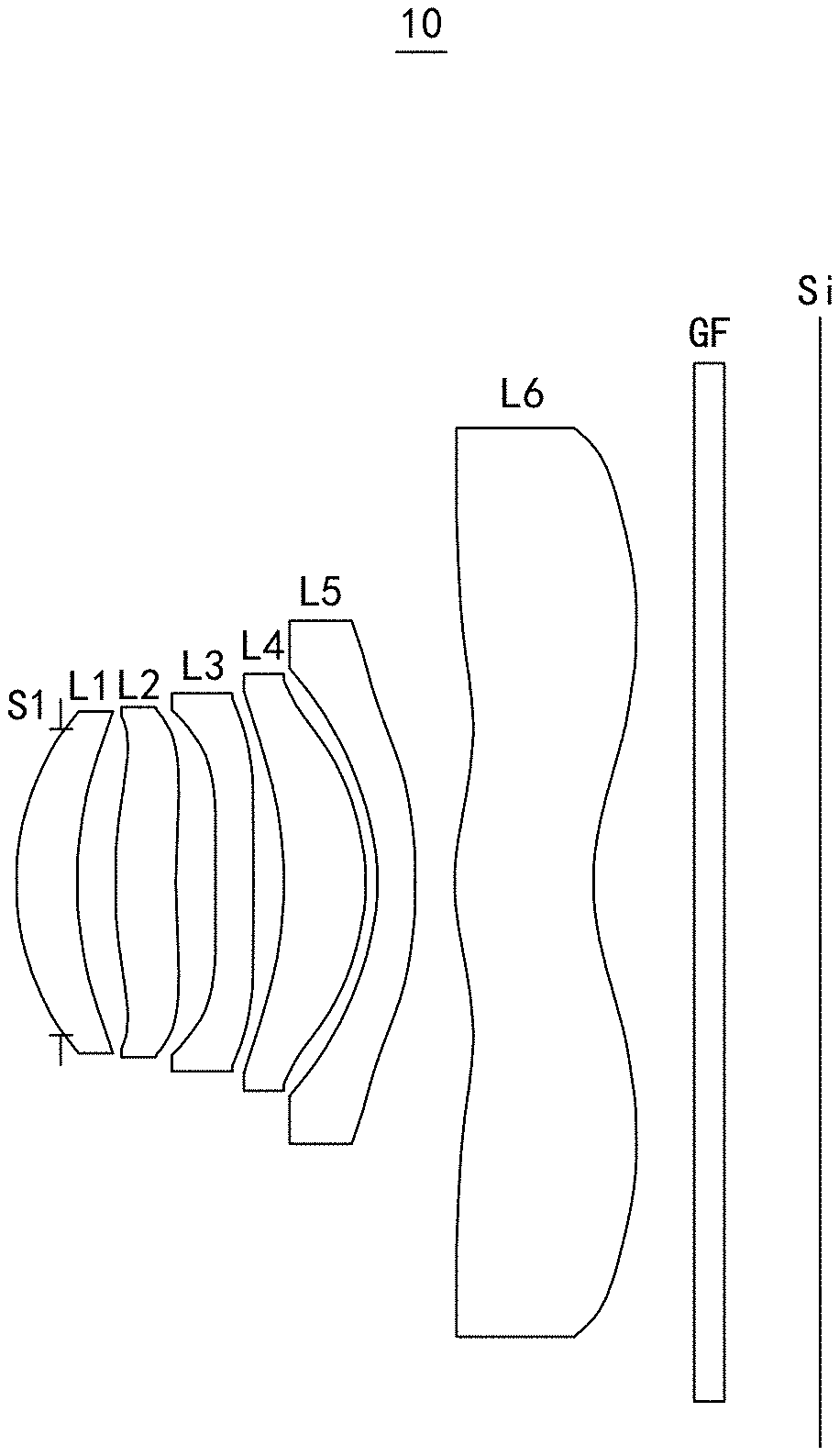
FIG. 1 is a schematic diagram of a camera optical lens in accordance with a first embodiment of the present invention;
FIG. 2 shows the longitudinal aberration of the camera optical lens shown in FIG. 1;
FIG. 3 shows the lateral color of the camera optical lens shown in FIG. 1;
FIG. 4 presents a schematic diagram of the field curvature and distortion of the camera optical lens shown in FIG. 1;
FIG. 5 is a schematic diagram of a camera optical lens in accordance with a second embodiment of the present invention;
FIG. 6 presents the longitudinal aberration of the camera optical lens shown in FIG. 5;
FIG. 7 presents the lateral color of the camera optical lens shown in FIG. 5;
FIG. 8 presents the field curvature and distortion of the camera optical lens shown in FIG. 5:
FIG. 9 is a schematic diagram of a camera optical lens in accordance with a third embodiment of the present invention;
FIG. 10 presents the longitudinal aberration of the camera optical lens shown in FIG. 9;
FIG. 11 presents the lateral color of the camera optical lens shown in FIG. 9;
FIG. 12 presents the field curvature and distortion of the camera optical lens shown in FIG. 9.
DETAILED DESCRIPTION OF THE EXEMPLARY EMBODIMENTS
The present disclosure will hereinafter be described in detail with reference to several exemplary embodiments. To make the technical problems to be solved, technical solutions and beneficial effects of the present disclosure more apparent, the present disclosure is described in further detail together with the figure and the embodiments. It should be understood the specific embodiments described hereby is only to explain the disclosure, not intended to limit the disclosure.
Embodiment 1
As referring to FIG. 1, the present invention provides a camera optical lens 10. FIG. 1 shows the camera optical lens 10 of embodiment 1 of the present invention, the camera optical lens 10 comprises 6 lenses. Specifically, from the object side to the image side, the camera optical lens 10 comprises in sequence: an aperture S1, a first lens L1, a second lens L2, a third lens L3, a fourth lens L4, a fifth lens L5, and a sixth lens L6. Optical element like optical filter GF can be arranged between the sixth lens L6 and the image surface Si.
The first lens L1 is made of plastic material, the second lens L2 is made of plastic material, the third lens L3 is made of plastic material, the fourth lens L4 is made of plastic material, the fifth lens L5 is made of glass material, and the sixth lens L6 is made of plastic material.
The second lens L2 has a positive refractive power, and the third lens L3 has a positive refractive power.
Here, the focal length of the whole camera optical lens 10 is defined as f, the focal length of the first lens is defined as f1. The camera optical lens 10 further satisfies the following condition: 0.5.ltoreq.f1/f.ltoreq.10. Condition 0.5.ltoreq.f1/f.ltoreq.10 fixes the positive refractive power of the first lens L1. If the lower limit of the set value is exceeded, although it benefits the ultra-thin development of lenses, but the positive refractive power of the first lens L1 will be too strong, problem like aberration is difficult to be corrected, and it is also unfavorable for wide-angle development of lens. On the contrary, if the upper limit of the set value is exceeded, the positive refractive power of the first lens L1 becomes too weak, it is then difficult to develop ultra-thin lenses. Preferably, the following condition shall be satisfied, 1.125.ltoreq.f1/f.ltoreq.7.995.
The refractive index of the fifth lens L5 is defined as n5. Here the following condition should be satisfied: 1.7.ltoreq.n5.ltoreq.2.2. This condition fixes the refractive index of the fifth lens L5, and refractive index within this range benefits the ultra-thin development of lenses, and it also benefits the correction of aberration. Preferably, the following condition shall be satisfied, 1.704.ltoreq.n5.ltoreq.2.1.
The thickness on-axis of the fifth lens L5 is defined as d9, and the total optical length of the camera optical lens 10 is defined as TTL. The following condition: 0.01.ltoreq.d9/TTL.ltoreq.0.2 should be satisfied. This condition fixes the ratio between the thickness on-axis of the fifth lens L5 and the total optical length TTL. When the condition is satisfied, it is beneficial for realization of the ultra-thin lens. Preferably, the condition 0.0275.ltoreq.d9/TTL.ltoreq.0.132 shall be satisfied.
When the focal length of the camera optical lens 10 of the present invention, the focal length of each lens, the refractive power of the related lens, and the total optical length, the thickness on-axis and the curvature radius of the camera optical lens satisfy the above conditions, the camera optical lens 10 has the advantage of high performance and satisfies the design requirement of low TTL.
In this embodiment, the first lens L1 has a positive refractive power with a convex object side surface relative to the proximal axis and a concave image side surface relative to the proximal axis.
The curvature radius of the object side surface of the first lens L1 is defined as R1, the curvature radius of the image side surface of the first lens L1 is defined as R2. The camera optical lens 10 further satisfies the following condition: -30.87.ltoreq.(R1+R2)/(R1-R2).ltoreq.-3.57, by which, the shape of the first lens L1 can be reasonably controlled and it is effectively for correcting spherical aberration of the camera optical lens. Preferably, the condition -19.29.ltoreq.(R1+R2)/(R1-R2).ltoreq.-4.47 shall be satisfied.
The thickness on-axis of the first lens L1 is defined as d1. The following condition: 0.13.ltoreq.d1.ltoreq.0.62 should be satisfied. When the condition is satisfied, it is beneficial for realization of the ultra-thin lens. Preferably, the condition 0.21.ltoreq.d1.ltoreq.0.5 shall be satisfied.
In this embodiment, the second lens L2 has a convex object side surface relative to the proximal axis and a concave image side surface relative to the proximal axis.
The focal length of the whole camera optical lens 10 is f, the focal length of the second lens L2 is f2. The following condition should be satisfied: 0.8.ltoreq.f2/f.ltoreq.4.64, which can effectively reduce the sensitivity of lens group used in camera and further enhance the imaging quality. Preferably, the condition 1.27.ltoreq.f2/f.ltoreq.3.71 should be satisfied.
The curvature radius of the object side surface of the second lens L2 is defined as R3, the curvature radius of the image side surface of the second lens L2 is defined as R4. The following condition should be satisfied: -6.12.ltoreq.(R3+R4)/(R3-R4).ltoreq.-1.11, which fixes the shape of the second lens L2 and when beyond this range, with the development into the direction of ultra-thin and wide-angle lenses, problem like chromatic aberration of the on-axis is difficult to be corrected. Preferably, the following condition shall be satisfied, -3.83.ltoreq.(R3+R4)/(R3-R4).ltoreq.-1.39.
The thickness on-axis of the second lens L2 is defined as d3. The following condition: 0.21.ltoreq.d3.ltoreq.0.71 should be satisfied. When the condition is satisfied, it is beneficial for realization of the ultra-thin lens. Preferably, the condition 0.33.ltoreq.d3.ltoreq.0.57 shall be satisfied.
In this embodiment, the third lens L3 has a convex object side surface relative to the proximal axis and a concave image side surface relative to the proximal axis.
The thickness on-axis of the third lens L3 is defined as d5. The following condition: 0.12.ltoreq.d5.ltoreq.0.39 should be satisfied. When the condition is satisfied, it is beneficial for realization of the ultra-thin lens. Preferably, the condition 0.19.ltoreq.d5.ltoreq.0.31 shall be satisfied.
In this embodiment, the fourth lens L4 has a positive refractive power with a concave object side surface relative to the proximal axis and a convex image side surface relative to the proximal axis.
The focal length of the whole camera optical lens 10 is f, the focal length of the fourth lens L4 is f4. The following condition should be satisfied: 0.51.ltoreq.f4/f.ltoreq.1.59, which can effectively reduce the sensitivity of lens group used in camera and further enhance the imaging quality. Preferably, the condition 0.81.ltoreq.f4/f.ltoreq.1.27 should be satisfied.
The curvature radius of the object side surface of the fourth lens L4 is defined as R7, the curvature radius of the image side surface of the fourth lens L4 is defined as R8. The following condition should be satisfied: 1.61.ltoreq.(R7+R8)/(R7-R8).ltoreq.5.03, by which, the shape of the fourth lens L4 is fixed, further, when beyond this range, with the development into the direction of ultra-thin and wide-angle lenses, problem like aberration of the off-axis picture angle is difficult to be corrected. Preferably, the following condition shall be satisfied, 2.58.ltoreq.(R7+R8)/(R7-R8).ltoreq.4.02.
The thickness on-axis of the fourth lens L4 is defined as d7. The following condition: 0.28.ltoreq.d7.ltoreq.0.86 should be satisfied. When the condition is satisfied, it is beneficial for realization of the ultra-thin lens. Preferably, the condition 0.45.ltoreq.d7.ltoreq.0.69 shall be satisfied.
In this embodiment, the fifth lens L5 has a negative refractive power with a concave object side surface relative to the proximal axis and a convex image side surface relative to the proximal axis.
The focal length of the whole camera optical lens 10 is f, the focal length of the fifth lens L5 is f5. The following condition should be satisfied: -1.93.ltoreq.f5/f.ltoreq.-0.53, which can effectively smooth the light angles of the camera and reduce the tolerance sensitivity. Preferably, the condition -1.21.ltoreq.f5/f.ltoreq.-0.66 should be satisfied.
The curvature radius of the object side surface of the fifth lens L5 is defined as R9, the curvature radius of the image side surface of the fifth lens L5 is defined as R10. The following condition should be satisfied: -5.51.ltoreq.(R9+R10)/(R9-R10).ltoreq.-1.49, by which, the shape of the fifth lens L5 is fixed, further, when beyond this range, with the development into the direction of ultra-thin and wide-angle lenses, problem like aberration of the off-axis picture angle is difficult to be corrected. Preferably, the following condition shall be satisfied, -3.45.ltoreq.(R9+R10)/(R9-R10).ltoreq.-1.87.
The thickness on-axis of the fifth lens L5 is defined as d9. The following condition: 0.13.ltoreq.d9.ltoreq.0.52 should be satisfied. When the condition is satisfied, it is beneficial for realization of the ultra-thin lens. Preferably, the condition 0.20.ltoreq.d9.ltoreq.0.42 shall be satisfied.
In this embodiment, the sixth lens L6 has a positive refractive power with a convex object side surface relative to the proximal axis and a concave image side surface relative to the proximal axis.
The focal length of the whole camera optical lens 10 is f, the focal length of the sixth lens L6 is f6. The following condition should be satisfied: 1.00.ltoreq.f6/f.ltoreq.4.2, which can effectively reduce the sensitivity of lens group used in camera and further enhance the imaging quality. Preferably, the condition 1.595.ltoreq.f6/f.ltoreq.3.36 should be satisfied.
The curvature radius of the object side surface of the sixth lens L6 is defined as R11, the curvature radius of the image side surface of the sixth lens L6 is defined as R12. The following condition should be satisfied: -94.45.ltoreq.(R11+R12)/(R11-R12).ltoreq.-18.52, by which, the shape of the sixth lens L6 is fixed, further, when beyond this range, with the development into the direction of ultra-thin and wide-angle lenses, problem like aberration of the off-axis picture angle is difficult to be corrected. Preferably, the following condition shall be satisfied, -59.03.ltoreq.(R11+R12)/(R11-R12).ltoreq.-23.15.
The thickness on-axis of the sixth lens L6 is defined as d11. The following condition: 0.44.ltoreq.d11.ltoreq.1.42 should be satisfied. When the condition is satisfied, it is beneficial for realization of the ultra-thin lens. Preferably, the condition 0.71.ltoreq.d11.ltoreq.1.14 shall be satisfied.
The focal length of the whole camera optical lens 10 is f, the combined focal length of the first lens L1 and the second lens L2 is f12. The following condition should be satisfied: 0.575.ltoreq.f12/f.ltoreq.1.96, which can effectively avoid the aberration and field curvature of the camera optical lens, and can suppress the rear focal length for realizing the ultra-thin lens. Preferably, the condition 0.91.ltoreq.f12/f.ltoreq.1.57 should be satisfied.
In this embodiment, the total optical length TTL of the camera optical lens 10 is less than or equal to 6.06 mm, it is beneficial for the realization of ultra-thin lenses. Preferably, the total optical length TTL of the camera optical lens 10 is less than or equal to 5.79 mm.
In this embodiment, the aperture F number of the camera optical lens 10 is less than or equal to 2.06. A large aperture has better imaging performance. Preferably, the aperture F number of the camera optical lens 10 is less than or equal to 2.02.
With such design, the total optical length TTL of the whole camera optical lens 10 can be made as short as possible, thus the miniaturization characteristics can be maintained.
In the following, an example will be used to describe the camera optical lens 10 of the present invention. The symbols recorded in each example are as follows. The unit of distance, radius and center thickness is mm.
TTL: Optical length (the distance on-axis from the object side surface of the first lens L1 to the image surface).
Preferably, inflexion points and/or arrest points can also be 2s arranged on the object side surface and/or image side surface of the lens, so that the demand for high quality imaging can be satisfied, the description below can be referred for specific implementable scheme.
The design information of the camera optical lens 10 in the first embodiment of the present invention is shown in the following, the unit of the focal length, distance, radius and center thickness is mm.
The design information of the camera optical lens 10 in the first embodiment of the present invention is shown in the tables 1 and 2.
TABLE-US-00001 TABLE 1 R d nd vd S1 .infin. d0= -0.306 R1 1.853 d1= 0.415 nd1 1.6806 v1 56.30 R2 2.682 d2= 0.263 R3 3.414 d3= 0.414 nd2 1.5140 v2 56.80 R4 6.727 d4= 0.271 R5 139.345 d5= 0.258 nd3 1.6515 v3 20.50 R6 139.243 d6= 0.209 R7 -3.010 d7= 0.558 nd4 1.7057 v4 55.02 R8 -1.627 d8= 0.079 R9 -1.538 d9= 0.261 nd5 1.7092 v5 25.60 R10 -3.880 d10= 0.270 R10 1.562 d11= 0.948 nd6 1.5418 v6 35.34 R12 1.630 d12= 0.683 R13 .infin. d13= 0.210 ndg 1.5168 vg 64.17 R14 .infin. d14= 0.667
Where:
In which, the meaning of the various symbols is as follows.
S1: Aperture;
R: The curvature radius of the optical surface, the central curvature radius in case of lens;
R1: The curvature radius of the object side surface of the first lens L1;
R2: The curvature radius of the image side surface of the first lens L1;
R3: The curvature radius of the object side surface of the second lens L2;
R4: The curvature radius of the image side surface of the second lens L2;
R5: The curvature radius of the object side surface of the third lens L3;
R6: The curvature radius of the image side surface of the third lens L3;
R7: The curvature radius of the object side surface of the fourth lens L4;
R8: The curvature radius of the image side surface of the fourth lens L4;
R9: The curvature radius of the object side surface of the fifth lens L5;
R10: The curvature radius of the image side surface of the fifth lens L5;
R11: The curvature radius of the object side surface of the sixth lens L6;
R12: The curvature radius of the image side surface of the sixth lens L6;
R13: The curvature radius of the object side surface of the optical filter GF;
R14: The curvature radius of the image side surface of the optical filter GF;
d: The thickness on-axis of the lens and the distance on-axis between the lens;
d0: The distance on-axis from aperture S1 to the object side surface of the first lens L1;
d1: The thickness on-axis of the first lens L1;
d2: The distance on-axis from the image side surface of the first lens L1 to the object side surface of the second lens L2;
d3: The thickness on-axis of the second lens L2;
d4: The distance on-axis from the image side surface of the second lens L2 to the object side surface of the third lens L3;
d5: The thickness on-axis of the third lens L3;
d6: The distance on-axis from the image side surface of the third lens L3 to the object side surface of the fourth lens L4;
d7: The thickness on-axis of the fourth lens L4;
d8: The distance on-axis from the image side surface of the fourth lens L4 to the object side surface of the fifth lens L5;
d9: The thickness on-axis of the fifth lens L5;
d10: The distance on-axis from the image side surface of the fifth lens L5 to the object side surface of the sixth lens L6;
d11: The thickness on-axis of the sixth lens L6;
d12: The distance on-axis from the image side surface of the sixth lens L6 to the object side surface of the optical filter GF;
d13: The thickness on-axis of the optical filter GF;
d14: The distance on-axis from the image side surface to the image surface of the optical filter GF;
nd: The refractive index of the d line;
nd1: The refractive index of the d line of the first lens L1;
nd2: The refractive index of the d line of the second lens L2;
nd3: The refractive index of the d line of the third lens L3;
nd4: The refractive power refractive index of the d line of the fourth lens L4;
nd5: The refractive index of the d line of the fifth lens L5;
nd6: The refractive index of the d line of the sixth lens L6;
ndg: The refractive power refractive index of the d line of the optical filter GF;
vd: The abbe number;
v1: The abbe number of the first lens L1;
v2: The abbe number of the second lens L2;
v3: The abbe number of the third lens L3;
v4: The abbe number of the fourth lens L4;
v5: The abbe number of the fifth lens L5;
v6: The abbe number of the sixth lens L6;
vg: The abbe number of the optical filter GF.
Table 2 shows the aspherical surface data of the camera optical lens 10 in the embodiment 1 of the present invention.
TABLE-US-00002 TABLE 2 Conic Index Aspherical Surface Index k A4 A6 A8 A10 A12 A14 A16 R1 5.37E-01 -1.01E-02 8.45E-03 -1.23E-02 1.35E-02 -9.64E-03 3.24E-03 -3.65E-04 R2 8.95E-01 -9.09E-03 -1.25E-03 3.68E-03 -7.47E-04 -8.41E-03 6.68E-03 -2.44E-03 R3 -1.78E+01 1.23E-02 -4.45E-02 -1.43E-03 3.49E-02 -6.49E-02 3.16E-02 -4.74E-03 R4 7.58E+00 -5.59E-02 -3.67E-02 -3.25E-02 5.44E-02 -6.10E-02 2.49E-02 -7.76E-04 R5 0.00E+00 -7.68E-02 -4.30E-02 -5.39E-02 -5.60E-03 2.63E-02 3.11E-03 -2.44E-03 R6 0.00E+00 -4.33E-02 4.71E-02 -1.42E-01 1.50E-01 -8.76E-02 2.09E-02 9.04E-04 R7 3.91E+00 -3.12E-02 3.60E-02 6.69E-02 -5.70E-02 -1.14E-02 2.20E-02 -4.20E-03 R8 -2.72E-01 1.03E-02 -3.81E-02 5.52E-02 -3.71E-02 1.61E-02 -2.52E-03 1.64E-04 R9 -4.86E+00 1.89E-02 -1.90E-01 3.64E-01 -4.35E-01 3.04E-01 -1.11E-01 1.60E-02 R10 -3.91E+00 -1.58E-01 2.43E-01 -2.57E-01 1.71E-01 -6.39E-02 1.23E-02 -9.64E-04 R11 -9.39E+00 -1.58E-01 3.10E-02 -2.02E-03 -2.74E-04 1.15E-05 7.23E-06 -6.54E-07 R12 -4.12E+00 -1.13E-01 1.70E-02 -2.94E-03 3.05E-04 -1.68E-05 4.43E-07 -9.15E-09
Among them, K is a conic index, A4, A6, A8, A10, A12, A14, A16 are aspheric surface indexes.
IH: Image height y=(x.sup.2/R)/[1+{1-(k+1)(x.sup.2/R.sup.2)}.sup.1/2]+A4x.sup.4+A6x.sup.6+- A8x.sup.8+A10x.sup.10+A12x.sup.12+A14x.sup.14+A16x.sup.16 (1)
For convenience, the aspheric surface of each lens surface uses the aspheric surfaces shown in the above condition (1). However, the present invention is not limited to the aspherical polynomials form shown in the condition (1).
Table 3 and table 4 show the inflexion points and the arrest point design data of the camera optical lens 10 lens in embodiment 1 of the present invention. In which, P1R1 and P1R2 represent respectively the object side surface and image side surface of the first lens L1, P2R1 and P2R2 represent respectively the object side surface and image side surface of the second lens L2, P3R1 and P3R2 represent respectively the object side surface and image side surface of the third lens L3, P4R1 and P4R2 represent respectively the object side surface and image side surface of the fourth lens L4, P5R1 and P5R2 represent respectively the object side surface and image side surface of the fifth lens L5, P6R1 and P6R2 represent respectively the object side surface and image side surface of the sixth lens L6. The data in the column named "inflexion point position" are the vertical distances from the inflexion points arranged on each lens surface to the optic axis of the camera optical lens 10. The data in the column named "arrest point position" are the vertical distances from the arrest points arranged on each lens surface to the optic axis of the camera optical lens 10.
TABLE-US-00003 TABLE 3 Inflexion point Inflexion point Inflexion point Inflexion point number position 1 position 2 position3 P1R1 0 P1R2 1 1.025 P2R1 1 0.635 P2R2 1 0.425 P3R1 2 0.095 1.135 P3R2 2 0.125 1.165 P4R1 2 1.115 1.295 P4R2 1 1.125 P5R1 1 1.395 P5R2 2 1.115 1.525 P6R1 3 0.485 1.525 2.225 P6R2 1 0.745
TABLE-US-00004 TABLE 4 Arrest point Arrest point Arrest point Arrest point number position 1 position 2 position 3 P1R1 0 P1R2 0 P2R1 1 0.935 P2R2 1 0.665 P3R1 1 0.155 P3R2 1 0.215 P4R1 0 P4R2 1 1.395 P5R1 0 P5R2 0 P6R1 3 1.045 2.155 2.275 P6R2 1 1.745
FIG. 2 and FIG. 3 show the longitudinal aberration and lateral color schematic diagrams after light with a wavelength of 486 nm, 588 nm and 656 nm passes the camera optical lens 10 in the first embodiment. FIG. 4 shows the field curvature and distortion schematic diagrams after light with a wavelength of 588 nm passes the camera optical lens 10 in the first embodiment, the field curvature S in FIG. 4 is a field curvature in the sagittal direction, T is a field curvature in the meridian direction.
Table 13 shows the various values of the embodiments 1, 2, 3, and the values corresponding with the parameters which are already specified in the conditions.
As shown in Table 13, the first embodiment satisfies the various conditions.
In this embodiment, the pupil entering diameter of the camera optical lens is 2.092 mm, the full vision field image height is 3.512 mm, the vision field angle in the diagonal direction is 80.03.degree., it has wide-angle and is ultra-thin, its on-axis and off-axis chromatic aberrations are fully corrected, and it has excellent optical characteristics.
Embodiment 2
Embodiment 2 is basically the same as embodiment 1, the meaning of its symbols is the same as that of embodiment 1, in the following, only the differences are described.
Table 5 and table 6 show the design data of the camera optical lens 20 in embodiment 2 of the present invention.
TABLE-US-00005 TABLE 5 R d nd Nd S1 .infin. d0= -0.304 R1 1.845 d1= 0.413 nd1 1.6683 v1 56.30 R2 2.692 d2= 0.260 R3 3.281 d3= 0.415 nd2 1.5140 v2 56.80 R4 6.615 d4= 0.280 R5 83.557 d5= 0.235 nd3 1.6390 v3 20.50 R6 83.465 d6= 0.216 R7 -3.000 d7= 0.563 nd4 1.7057 v4 52.68 R8 -1.611 d8= 0.078 R9 -1.642 d9= 0.250 nd5 2.0025 v5 25.60 R10 -3.511 d10= 0.266 R11 1.464 d11= 0.935 nd6 1.6018 v6 35.24 R12 1.572827 d12= 0.703 R13 .infin. d13= 0.210 ndg 1.5168 vg 64.17 R14 .infin. d14= 0.687
Table 6 shows the aspherical surface data of each lens of the camera optical lens 20 in embodiment 2 of the present invention.
TABLE-US-00006 TABLE 6 Conic index Aspherical Surface Index k A4 A6 A8 A10 A12 A14 A16 R1 5.32E-01 -1.04E-02 8.25E-03 -1.25E-02 1.34E-02 -9.69E-03 3.22E-03 -3.65E-04 R2 8.58E-01 -9.32E-03 -1.86E-03 3.61E-03 -7.09E-04 -8.40E-03 6.64E-03 -2.50E-03 R3 -1.67E+01 1.28E-02 -4.53E-02 -2.15E-03 3.45E-02 -6.51E-02 3.15E-02 -4.73E-03 R4 5.30E+00 -5.75E-02 -3.70E-02 -3.24E-02 5.45E-02 -6.10E-02 2.49E-02 -8.21E-04 R5 0.00E+00 -7.94E-02 -4.35E-02 -5.38E-02 -5.42E-03 2.64E-02 3.23E-03 -2.35E-03 R6 0.00E+00 -4.12E-02 4.79E-02 -1.42E-01 1.49E-01 -8.77E-02 2.09E-02 8.80E-04 R7 3.97E+00 -2.95E-02 3.58E-02 6.68E-02 -5.69E-02 -1.13E-02 2.21E-02 -4.17E-03 R8 -2.68E-01 1.10E-02 -3.89E-02 5.49E-02 -3.71E-02 1.61E-02 -2.48E-03 1.88E-04 R9 -4.27E+00 1.94E-02 -1.87E-01 3.65E-01 -4.35E-01 3.04E-01 -1.11E-01 1.60E-02 R10 -4.09E+00 -1.60E-01 2.42E-01 -2.57E-01 1.71E-01 -6.39E-02 1.23E-02 -9.64E-04 R11 -8.99E+00 -1.60E-01 3.09E-02 -2.02E-03 -2.71E-04 1.18E-05 7.23E-06 -6.61E-07 R12 -4.51E+00 -1.13E-01 1.70E-02 -2.94E-03 3.06E-04 -1.68E-05 4.41E-07 -9.47E-09
Table 7 and table 8 show the inflexion points and the arrest point design data of the camera optical lens 20 lens in embodiment 2 of the present invention.
TABLE-US-00007 TABLE 7 Inflexion point Inflexion point Inflexion point Inflexion point number position 1 position 2 position3 P1R1 0 P1R2 1 1.015 P2R1 1 0.635 P2R2 1 0.415 P3R1 2 0.115 1.125 P3R2 2 0.165 1.175 P4R1 2 1.115 1.275 P4R2 1 1.125 P5R1 1 1.395 P5R2 2 1.165 1.465 P6R1 3 0.485 1.535 2.245 P6R2 1 0.725
TABLE-US-00008 TABLE 8 Arrest point Arrest point Arrest point Arrest point number position 1 position 2 position 3 P1R1 0 P1R2 0 P2R1 1 0.935 P2R2 1 0.665 P3R1 1 0.195 P3R2 1 0.285 P4R1 0 P4R2 1 1.395 P5R1 0 P5R2 0 P6R1 3 1.055 2.175 2.295 P6R2 1 1.715
FIG. 6 and FIG. 7 show the longitudinal aberration and lateral color schematic diagrams after light with a wavelength of 486 nm, 588 nm and 656 nm passes the camera optical lens 20 in the second embodiment. FIG. 8 shows the field curvature and distortion schematic diagrams after light with a wavelength of 588 nm passes the camera optical lens 20 in the second embodiment.
As shown in Table 13, the second embodiment satisfies the various conditions.
In this embodiment, the pupil entering diameter of the camera optical lens is 2.086 mm, the full vision field image height is 3.512 mm, the vision field angle in the diagonal direction is 80.18.degree., it has wide-angle and is ultra-thin, its on-axis and off-axis chromatic aberrations are fully corrected, and it has excellent optical characteristics.
Embodiment 3
Embodiment 3 is basically the same as embodiment 1, the meaning of its symbols is the same as that of embodiment 1, in the following, only the differences are described.
Table 9 and table 10 show the design data of the camera optical lens 30 in embodiment 3 of the present invention.
TABLE-US-00009 TABLE 9 R d nd Nd S1 .infin. d0= -0.233 R1 1.971 d1= 0.265 nd1 1.5187 v1 56.30 R2 2.244 d2= 0.120 R3 2.459 d3= 0.472 nd2 1.5140 v2 56.80 R4 9.850 d4= 0.307 R5 15.282 d5= 0.241 nd3 1.5397 v3 22.85 R6 15.197 d6= 0.249 R7 -3.053 d7= 0.575 nd4 1.7057 v4 70.00 R8 -1.609 d8= 0.086 R9 -1.562 d9= 0.347 nd5 1.7099 v5 25.60 R10 -4.084 d10= 0.216 R11 1.321 d11= 0.887 nd6 1.5408 v6 37.10 R12 1.390418 d12= 0.746 R13 .infin. d13= 0.210 ndg 1.5168 vg 64.17 R14 .infin. d14= 0.731
Table 10 shows the aspherical surface data of each lens of the camera optical lens 30 in embodiment 3 of the present invention.
TABLE-US-00010 TABLE 10 Conic Index Aspherical Surface Index k A4 A6 A8 A10 A12 A14 A16 R1 5.20E-01 -1.02E-02 6.27E-03 -1.30E-02 1.37E-02 -9.29E-03 3.46E-03 -5.26E-04 R2 2.00E-01 -2.65E-02 -2.71E-03 2.43E-03 -2.34E-03 -9.58E-03 6.34E-03 -2.17E-03 R3 -8.23E+00 2.51E-02 -4.68E-02 -5.13E-03 3.30E-02 -6.63E-02 3.01E-02 -6.25E-03 R4 2.38E+01 -5.08E-02 -3.46E-02 -3.27E-02 5.36E-02 -6.15E-02 2.48E-02 -7.49E-04 R5 0.00E+00 -8.69E-02 -4.29E-02 -5.32E-02 -4.51E-03 2.71E-02 3.75E-03 -2.08E-03 R6 0.00E+00 -4.75E-02 4.49E-02 -1.43E-01 1.49E-01 -8.83E-02 2.06E-02 8.16E-04 R7 3.90E+00 -3.01E-02 3.51E-02 6.69E-02 -5.69E-02 -1.14E-02 2.19E-02 -4.38E-03 R8 -2.74E-01 1.03E-02 -3.78E-02 5.47E-02 -3.75E-02 1.59E-02 -2.52E-03 2.26E-04 R9 -6.21E+00 1.61E-02 -1.88E-01 3.65E-01 -4.35E-01 3.04E-01 -1.11E-01 1.60E-02 R10 -4.42E+00 -1.55E-01 2.43E-01 -2.57E-01 1.71E-01 -6.39E-02 1.23E-02 -9.64E-04 R11 -7.27E+00 -1.55E-01 3.05E-02 -2.06E-03 -2.69E-04 1.29E-05 7.15E-06 -6.73E-07 R12 -4.09E+00 -1.13E-01 1.70E-02 -2.95E-03 3.03E-04 -1.69E-05 4.47E-07 -8.50E-09
Table 11 and table 12 show the inflexion points and the arrest point design data of the camera optical lens 30 lens in embodiment 3 of the present invention.
TABLE-US-00011 TABLE 11 Inflexion point Inflexion point Inflexion point Inflexion point number position 1 position 2 position 3 P1R1 0 P1R2 1 0.925 P2R1 1 0.695 P2R2 1 0.375 P3R1 2 0.245 1.095 P3R2 2 0.365 1.215 P4R1 2 1.125 1.315 P4R2 1 1.135 P5R1 1 1.405 P5R2 2 1.095 1.715 P6R1 3 0.505 1.595 2.065 P6R2 1 0.745
TABLE-US-00012 TABLE 12 Arrest point Arrest point number position 1 P1R1 0 P1R2 0 P2R1 1 0.965 P2R2 1 0.595 P3R1 1 0.405 P3R2 1 0.595 P4R1 0 P4R2 0 P5R1 0 P5R2 0 P6R1 1 1.135 P6R2 1 1.845
FIG. 10 and FIG. 11 show the longitudinal aberration and lateral color schematic diagrams after light with a wavelength of 486 nm, 588 nm and 656 nm passes the camera optical lens 30 in the third embodiment. FIG. 12 shows the field curvature and distortion schematic diagrams after light with a wavelength of 588 nm passes the camera optical lens 30 in the third embodiment.
As shown in Table 13, the third embodiment satisfies the various conditions.
In this embodiment, the pupil entering diameter of the camera optical lens is 1.957 mm, the full vision field image height is 3.512 mm, the vision field angle in the diagonal direction is 83.79.degree., it has wide-angle and is ultra-thin, its on-axis and off-axis chromatic aberrations are fully corrected, and it has excellent optical characteristics.
TABLE-US-00013 TABLE 13 Embodiment Embodiment Embodiment 1 2 3 f 4.183227866 4.172143734 3.914532977 f1 7.323642953 7.347240238 23.44938867 f2 12.94009748 12.1542058 6.238774613 f3 9.56E+12 1.00E+10 3.29E+13 f4 4.300807447 4.223856802 4.140313739 f5 -3.766827755 -3.298724921 -3.779336744 f6 11.7226863 8.30584367 8.904844562 f12 4.833621917 4.739294463 5.116545745 (R1 + R2)/(R1 - R2) -5.470192599 -5.360602103 -15.43261256 (R3 + R4)/(R3 - R4) -3.061210496 -2.968665597 -1.66522099 (R7 + R8)/(R7 - R8) 3.353751644 3.320712425 3.229988225 (R9 + R10)/(R9 - -2.31341657 -2.757325541 -2.238788614 R10) (R11 + R12)/(R11 - -47.22590363 -27.77624754 -38.8163751 R12) f1/f 1.75071576 1.761022799 5.990341326 f2/f 3.093328381 2.913180027 1.593746853 f4/f 1.028107382 1.012394843 1.057677573 f5/f -0.900459615 -0.790654669 -0.965462998 f6/f 2.802306419 1.990785601 2.274816591 f12/f 1.155476601 1.135937486 1.307064157 d1 0.415000388 0.412750303 0.265207605 d3 0.413551573 0.415029777 0.472228637 d5 0.258455563 0.234672084 0.241182865 d7 0.558222314 0.562820801 0.575292708 d9 0.260998419 0.250046589 0.346780032 d11 0.948142399 0.934893526 0.887394579 Fno 2.000003761 2.00000179 1.999996412 TTL 5.506285314 5.509807727 5.453604356 d1/TTL 0.075368486 0.074911925 0.048629785 d3/TTL 0.075105366 0.075325637 0.08659019 d5/TTL 0.04693828 0.042591701 0.044224489 d7/TTL 0.101379112 0.1021489 0.10548853 d9/TTL 0.04740009 0.04538209 0.06358731 d11/TTL 0.172192748 0.169678067 0.16271708 n1 1.680561 1.668287 1.518659 n2 1.514 1.514 1.514 n3 1.651491 1.639018 1.539718 n4 1.705679 1.705679 1.705679 n5 1.709195 2.002463 1.70992 n6 1.541814 1.601758 1.540775 v1 56.3 56.3 56.3 v2 56.8 56.8 56.8 v3 20.499626 20.499471 22.852293 v4 55.018517 52.682222 70.00021 v5 25.6 25.6 25.6 v6 35.344735 35.236904 37.097636
It is to be understood, however, that even though numerous characteristics and advantages of the present exemplary embodiments have been set forth in the foregoing description, together with details of the structures and functions of the embodiments, the disclosure is illustrative only, and changes may be made in detail, especially in matters of shape, size, and arrangement of parts within the principles of the invention to the full extent indicated by the broad general meaning of the terms where the appended claims are expressed.
* * * * *
D00000
D00001
D00002
D00003
D00004
D00005
D00006
D00007
XML
uspto.report is an independent third-party trademark research tool that is not affiliated, endorsed, or sponsored by the United States Patent and Trademark Office (USPTO) or any other governmental organization. The information provided by uspto.report is based on publicly available data at the time of writing and is intended for informational purposes only.
While we strive to provide accurate and up-to-date information, we do not guarantee the accuracy, completeness, reliability, or suitability of the information displayed on this site. The use of this site is at your own risk. Any reliance you place on such information is therefore strictly at your own risk.
All official trademark data, including owner information, should be verified by visiting the official USPTO website at www.uspto.gov. This site is not intended to replace professional legal advice and should not be used as a substitute for consulting with a legal professional who is knowledgeable about trademark law.