Systems and methods for determining relationships between datasets
Colgrove , et al. March 9, 2
U.S. patent number 10,942,947 [Application Number 15/900,289] was granted by the patent office on 2021-03-09 for systems and methods for determining relationships between datasets. This patent grant is currently assigned to Palantir Technologies Inc.. The grantee listed for this patent is Palantir Technologies Inc.. Invention is credited to Caitlin Colgrove, Gabrielle Javitt, Harsh Pandey.


| United States Patent | 10,942,947 |
| Colgrove , et al. | March 9, 2021 |
Systems and methods for determining relationships between datasets
Abstract
A first dataset from one or more databases and a second dataset from the one or more databases may be identified. The first dataset may contain first data while the second dataset may contain second data. A first relationship measure may be computed for the first dataset, where the first relationship measure is configured to represent the first data in a first condensed format. A second relationship measure may be computed for the second dataset, where the second relationship measure is configured to represent the second data in a second condensed format. A join key may be computed using the first relationship measure and the second relationship measure. The join key may represent a correspondence area between the first dataset and the second dataset. An interactive user interface element may be configured to display a graphical depiction of the correspondence area between the first dataset and the second dataset.
| Inventors: | Colgrove; Caitlin (Palo Alto, CA), Pandey; Harsh (New York, NY), Javitt; Gabrielle (New York, NY) | ||||||||||
|---|---|---|---|---|---|---|---|---|---|---|---|
| Applicant: |
|
||||||||||
| Assignee: | Palantir Technologies Inc.
(Palo Alto, CA) |
||||||||||
| Family ID: | 1000005410708 | ||||||||||
| Appl. No.: | 15/900,289 | ||||||||||
| Filed: | February 20, 2018 |
Prior Publication Data
| Document Identifier | Publication Date | |
|---|---|---|
| US 20190018889 A1 | Jan 17, 2019 | |
Related U.S. Patent Documents
| Application Number | Filing Date | Patent Number | Issue Date | ||
|---|---|---|---|---|---|
| 62533517 | Jul 17, 2017 | ||||
| Current U.S. Class: | 1/1 |
| Current CPC Class: | G06F 16/23 (20190101); G06F 16/284 (20190101); G06F 16/2456 (20190101) |
| Current International Class: | G06F 16/28 (20190101); G06F 16/23 (20190101); G06F 16/2455 (20190101) |
References Cited [Referenced By]
U.S. Patent Documents
| 4881179 | November 1989 | Vincent |
| 5241625 | August 1993 | Epard et al. |
| 5845300 | December 1998 | Comer |
| 5999911 | December 1999 | Berg et al. |
| 6065026 | May 2000 | Cornelia et al. |
| 6101479 | August 2000 | Shaw |
| 6232971 | May 2001 | Haynes |
| 6237138 | May 2001 | Hameluck et al. |
| 6243706 | June 2001 | Moreau et al. |
| 6279018 | August 2001 | Kudrolli et al. |
| 6370538 | April 2002 | Lamping et al. |
| 6430305 | August 2002 | Decker |
| 6523019 | February 2003 | Borthwick |
| 6642945 | November 2003 | Sharpe |
| 6665683 | December 2003 | Meltzer |
| 6850317 | February 2005 | Mullins et al. |
| 6944777 | September 2005 | Belani et al. |
| 6944821 | September 2005 | Bates et al. |
| 6967589 | November 2005 | Peters |
| 6978419 | December 2005 | Kantrowitz |
| 7086028 | August 2006 | Davis et al. |
| 7174377 | February 2007 | Bernard et al. |
| 7194680 | March 2007 | Roy et al. |
| 7213030 | May 2007 | Jenkins |
| 7392254 | June 2008 | Jenkins |
| 7441182 | October 2008 | Beilinson et al. |
| 7441219 | October 2008 | Perry et al. |
| 7627812 | December 2009 | Chamberlain et al. |
| 7634717 | December 2009 | Chamberlain et al. |
| 7716140 | May 2010 | Nielsen et al. |
| 7765489 | July 2010 | Shah |
| 7770100 | August 2010 | Chamberlain et al. |
| 7877421 | January 2011 | Berger et al. |
| 7880921 | February 2011 | Dattilo et al. |
| 7941336 | May 2011 | Robin-Jan |
| 7958147 | June 2011 | Turner et al. |
| 7962848 | June 2011 | Bertram |
| 7966199 | June 2011 | Frasher |
| 8001465 | August 2011 | Kudrolli et al. |
| 8001482 | August 2011 | Bhattiprolu et al. |
| 8010507 | August 2011 | Poston et al. |
| 8073857 | December 2011 | Sreekanth |
| 8191005 | May 2012 | Baier et al. |
| 8225201 | July 2012 | Michael |
| 8290838 | October 2012 | Thakur et al. |
| 8302855 | November 2012 | Ma et al. |
| 8312367 | November 2012 | Foster |
| 8392556 | March 2013 | Goulet et al. |
| 8527949 | September 2013 | Pleis et al. |
| 8620641 | December 2013 | Farnsworth et al. |
| 8682696 | March 2014 | Shanmugam |
| 8688573 | April 2014 | Ruknoic et al. |
| 8732574 | May 2014 | Burr et al. |
| 8799313 | August 2014 | Satlow |
| 8807948 | August 2014 | Luo et al. |
| 8930874 | January 2015 | Duff et al. |
| 8938686 | January 2015 | Erenrich et al. |
| 8984390 | March 2015 | Aymeloglu et al. |
| 9058315 | June 2015 | Burr et al. |
| 9165100 | October 2015 | Begur et al. |
| 9286373 | March 2016 | Elliot et al. |
| 9348880 | May 2016 | Kramer et al. |
| 2001/0021936 | September 2001 | Bertram |
| 2002/0032677 | March 2002 | Morgenthaler et al. |
| 2002/0095360 | July 2002 | Joao |
| 2002/0103705 | August 2002 | Brady |
| 2002/0196229 | December 2002 | Chen et al. |
| 2003/0028560 | February 2003 | Kudrolli et al. |
| 2003/0036927 | February 2003 | Bowen |
| 2003/0061132 | March 2003 | Mason et al. |
| 2003/0093755 | May 2003 | O'Carroll |
| 2003/0126102 | July 2003 | Borthwick |
| 2004/0034570 | February 2004 | Davis |
| 2004/0044648 | March 2004 | Anfindsen et al. |
| 2004/0078451 | April 2004 | Dietz et al. |
| 2004/0205492 | October 2004 | Newsome |
| 2004/0236688 | November 2004 | Bozeman |
| 2004/0236711 | November 2004 | Nixon et al. |
| 2005/0010472 | January 2005 | Quatse et al. |
| 2005/0028094 | February 2005 | Allyn |
| 2005/0039116 | February 2005 | Slack-Smith |
| 2005/0091186 | April 2005 | Elish |
| 2005/0125715 | June 2005 | Di Franco et al. |
| 2006/0026561 | February 2006 | Bauman et al. |
| 2006/0031779 | February 2006 | Theurer et al. |
| 2006/0045470 | March 2006 | Poslinski et al. |
| 2006/0053097 | March 2006 | King et al. |
| 2006/0053170 | March 2006 | Hill et al. |
| 2006/0059423 | March 2006 | Lehmann et al. |
| 2006/0074866 | April 2006 | Chamberlain et al. |
| 2006/0080139 | April 2006 | Mainzer |
| 2006/0129746 | June 2006 | Porter |
| 2006/0136513 | June 2006 | Ngo et al. |
| 2006/0143075 | June 2006 | Carr et al. |
| 2006/0155654 | July 2006 | Plessis et al. |
| 2006/0178915 | August 2006 | Chao |
| 2006/0265417 | November 2006 | Amato et al. |
| 2006/0277460 | December 2006 | Forstall et al. |
| 2007/0000999 | January 2007 | Kubo et al. |
| 2007/0018986 | January 2007 | Hauser |
| 2007/0043686 | February 2007 | Teng et al. |
| 2007/0061752 | March 2007 | Cory |
| 2007/0113164 | May 2007 | Hansen et al. |
| 2007/0136095 | June 2007 | Weinstein |
| 2007/0168871 | July 2007 | Jenkins |
| 2007/0174760 | July 2007 | Chamberlain et al. |
| 2007/0185850 | August 2007 | Walters et al. |
| 2007/0219952 | September 2007 | Ahmed |
| 2007/0245339 | October 2007 | Bauman et al. |
| 2007/0284433 | December 2007 | Domenica et al. |
| 2007/0299697 | December 2007 | Friedlander et al. |
| 2008/0016155 | January 2008 | Khalatian |
| 2008/0091693 | April 2008 | Murthy |
| 2008/0109714 | May 2008 | Kumar et al. |
| 2008/0172607 | July 2008 | Baer |
| 2008/0177782 | July 2008 | Poston et al. |
| 2008/0186904 | August 2008 | Koyama et al. |
| 2008/0249820 | October 2008 | Pathria |
| 2008/0276167 | November 2008 | Michael |
| 2008/0288475 | November 2008 | Kim et al. |
| 2008/0313132 | December 2008 | Hao et al. |
| 2008/0313243 | December 2008 | Poston et al. |
| 2009/0024962 | January 2009 | Gotz |
| 2009/0031401 | January 2009 | Cudich et al. |
| 2009/0043801 | February 2009 | LeClair |
| 2009/0089651 | April 2009 | Herberger et al. |
| 2009/0106178 | April 2009 | Chu |
| 2009/0112678 | April 2009 | Luzardo |
| 2009/0112745 | April 2009 | Stefanescu |
| 2009/0150868 | June 2009 | Chakra et al. |
| 2009/0164934 | June 2009 | Bhattiprolu et al. |
| 2009/0177962 | July 2009 | Gusmorino et al. |
| 2009/0187546 | July 2009 | Whyte et al. |
| 2009/0199106 | August 2009 | Jonsson et al. |
| 2009/0216562 | August 2009 | Faulkner et al. |
| 2009/0248757 | October 2009 | Havewala et al. |
| 2009/0249178 | October 2009 | Ambrosino et al. |
| 2009/0249244 | October 2009 | Robinson et al. |
| 2009/0271343 | October 2009 | Vaiciulis et al. |
| 2009/0281839 | November 2009 | Lynn et al. |
| 2009/0282068 | November 2009 | Shockro et al. |
| 2009/0287470 | November 2009 | Farnsworth et al. |
| 2009/0307049 | December 2009 | Elliott et al. |
| 2009/0313463 | December 2009 | Pang et al. |
| 2009/0319891 | December 2009 | MacKinlay |
| 2010/0004857 | January 2010 | Pereira et al. |
| 2010/0057622 | March 2010 | Faith et al. |
| 2010/0070842 | March 2010 | Aymeloglu et al. |
| 2010/0070844 | March 2010 | Aymeloglu et al. |
| 2010/0076813 | March 2010 | Ghosh et al. |
| 2010/0098318 | April 2010 | Anderson |
| 2010/0122152 | May 2010 | Chamberlain et al. |
| 2010/0223260 | September 2010 | Wu |
| 2010/0238174 | September 2010 | Haub et al. |
| 2010/0262901 | October 2010 | DiSalvo |
| 2010/0280851 | November 2010 | Merkin |
| 2010/0306722 | December 2010 | LeHoty et al. |
| 2010/0313239 | December 2010 | Chakra et al. |
| 2011/0047540 | February 2011 | Williams et al. |
| 2011/0074788 | March 2011 | Regan et al. |
| 2011/0093327 | April 2011 | Fordyce, III et al. |
| 2011/0099133 | April 2011 | Chang et al. |
| 2011/0107196 | May 2011 | Foster |
| 2011/0161409 | June 2011 | Nair |
| 2011/0173093 | July 2011 | Psota et al. |
| 2011/0179048 | July 2011 | Satlow |
| 2011/0208565 | August 2011 | Ross et al. |
| 2011/0225482 | September 2011 | Chan et al. |
| 2012/0004894 | January 2012 | Butler |
| 2012/0022945 | January 2012 | Falkenborg et al. |
| 2012/0059853 | March 2012 | Jagota |
| 2012/0065987 | March 2012 | Farooq et al. |
| 2012/0084117 | April 2012 | Tavares et al. |
| 2012/0084184 | April 2012 | Raleigh |
| 2012/0123989 | May 2012 | Yu et al. |
| 2012/0188252 | July 2012 | Law |
| 2012/0197657 | August 2012 | Prodanovic |
| 2012/0197660 | August 2012 | Prodanovic |
| 2012/0215784 | August 2012 | King et al. |
| 2012/0226590 | September 2012 | Love et al. |
| 2012/0266245 | October 2012 | McDougal et al. |
| 2012/0284670 | November 2012 | Kashik et al. |
| 2012/0304244 | November 2012 | Xie et al. |
| 2012/0323829 | December 2012 | Stokes et al. |
| 2013/0016106 | January 2013 | Yip et al. |
| 2013/0055264 | February 2013 | Burr et al. |
| 2013/0097482 | April 2013 | Marantz et al. |
| 2013/0124567 | May 2013 | Balinsky et al. |
| 2013/0151305 | June 2013 | Akinola et al. |
| 2013/0151453 | June 2013 | Bhanot et al. |
| 2013/0151502 | June 2013 | Yoon |
| 2013/0166480 | June 2013 | Popescu et al. |
| 2013/0262527 | October 2013 | Hunter et al. |
| 2013/0262528 | October 2013 | Foit |
| 2013/0263019 | October 2013 | Castellanos et al. |
| 2013/0288719 | October 2013 | Alonzo |
| 2014/0089339 | March 2014 | Siddiqui et al. |
| 2014/0129936 | May 2014 | Richards et al. |
| 2014/0156635 | June 2014 | Grochowski |
| 2014/0208281 | July 2014 | Ming |
| 2014/0222793 | August 2014 | Sadkin et al. |
| 2014/0244284 | August 2014 | Smith |
| 2014/0280143 | September 2014 | Milenova |
| 2014/0358829 | December 2014 | Hurwitz |
| 2015/0026622 | January 2015 | Roaldson et al. |
| 2015/0073954 | March 2015 | Braff |
| 2015/0089353 | March 2015 | Folkening |
| 2015/0100907 | April 2015 | Erenrich et al. |
| 2015/0106379 | April 2015 | Elliot et al. |
| 2015/0186483 | July 2015 | Tappan et al. |
| 2015/0212663 | July 2015 | Papale et al. |
| 2015/0254220 | September 2015 | Burr et al. |
| 2016/0062555 | March 2016 | Ward et al. |
| 2016/0098176 | April 2016 | Cervelli et al. |
| 2016/0110369 | April 2016 | Cervelli et al. |
| 2016/0162519 | June 2016 | Stowe et al. |
| 2017/0024384 | January 2017 | Kant |
| 2018/0039399 | February 2018 | Kaltegaertner |
| 2018/0046674 | February 2018 | Grochowski |
| 2018/0074786 | March 2018 | Oberbreckling |
| 2018/0075104 | March 2018 | Oberbreckling |
| 2018/0075115 | March 2018 | Murray |
| 2013251186 | Nov 2015 | AU | |||
| 102054015 | May 2014 | CN | |||
| 1672527 | Jun 2006 | EP | |||
| 2993595 | Mar 2016 | EP | |||
| 3002691 | Apr 2016 | EP | |||
| 3009943 | Apr 2016 | EP | |||
| 3032441 | Jun 2016 | EP | |||
| WO 01/025906 | Apr 2001 | WO | |||
| WO 2001/088750 | Nov 2001 | WO | |||
| WO 2007/133206 | Nov 2007 | WO | |||
| WO 2010/030913 | Mar 2010 | WO | |||
| WO 2010/030914 | Mar 2010 | WO | |||
| WO 2012/119008 | Sep 2012 | WO | |||
Other References
|
"GrabUp--What a Timesaver!" <http://atlchris.com/191/grabup/>, Aug. 11, 2008, pp. 3. cited by applicant . "Remove a Published Document or Blog Post," Sharing and Collaborating on Blog Post. cited by applicant . Abbey, Kristen, "Review of Google Docs," May 1, 2007, pp. 2. cited by applicant . Adams et al., "Worklets: A Service-Oriented Implementation of Dynamic Flexibility in Workflows," R. Meersman, Z. Tari et al. (Eds.): OTM 2006, LNCS, 4275, pp. 291-308, 2006. cited by applicant . Bluttman et al., "Excel Formulas and Functions for Dummies," 2005, Wiley Publishing, Inc., pp. 280, 284-286. cited by applicant . Chaudhuri et al., "An Overview of Business Intelligence Technology," Communications of the ACM, Aug. 2011, vol. 54, No. 8. cited by applicant . Conner, Nancy, "Google Apps: The Missing Manual," May 1, 2008, pp. 15. cited by applicant . Ferreira et al., "A Scheme for Analyzing Electronic Payment Systems," Basil 1997. cited by applicant . Galliford, Miles, "SnagIt Versus Free Screen Capture Software: Critical Tools for Website Owners," <http://www.subhub.com/articles/free-screen-capture-software>, Mar. 27, 2008, pp. 11. cited by applicant . Gu et al., "Record Linkage: Current Practice and Future Directions," Jan. 15, 2004, pp. 32. cited by applicant . Hua et al., "A Multi-attribute Data Structure with Parallel Bloom Filters for Network Services", HiPC 2006, LNCS 4297, pp. 277-288, 2006. cited by applicant . JetScreenshot.com, "Share Screenshots via Internet in Seconds," <http://web.archive.org/web/20130807164204/http://www.jetscreenshot.co- m/>, Aug. 7, 2013, pp. 1. cited by applicant . Kwout, <http://web.archive.org/web/20080905132448/http://www.kwout.com/- > Sep. 5, 2008, pp. 2. cited by applicant . Microsoft Windows, "Microsoft Windows Version 2002 Print Out 2," 2002, pp. 1-6. cited by applicant . Microsoft, "Registering an Application to a URI Scheme," <http://msdn.microsoft.com/en-us/library/aa767914.aspx>, printed Apr. 4, 2009 in 4 pages. cited by applicant . Microsoft, "Using the Clipboard," <http://msdn.microsoft.com/en-us/library/ms649016.aspx>, printed Jun. 8, 2009 in 20 pages. cited by applicant . Nitro, "Trick: How to Capture a Screenshot as PDF, Annotate, Then Share It," <http://blog.nitropdf.com/2008/03/04/trick-how-to-capture-a-scree- nshot-as-pdf-annotate-it-then-share/>, Mar. 4, 2008, pp. 2. cited by applicant . Online Tech Tips, "Clip2Net--Share files, folders and screenshots easily," <http://www.online-tech-tips.com/free-software-downloads/share-files-f- olders-screenshots/>, Apr. 2, 2008, pp. 5. cited by applicant . O'Reilly.com, http://oreilly.com/digitalmedia/2006/01/01/mac-os-x-screenshot-secrets.ht- ml published Jan. 1, 2006 in 10 pages. cited by applicant . Schroder, Stan, "15 Ways to Create Website Screenshots," <http://mashable.com/2007/08/24/web-screenshots/>, Aug. 24, 2007, pp. 2. cited by applicant . SnagIt, "SnagIt 8.1.0 Print Out 2," Software release date Jun. 15, 2006, pp. 1-3. cited by applicant . SnagIt, "SnagIt 8.1.0 Print Out," Software release date Jun. 15, 2006, pp. 6. cited by applicant . SnagIt, "SnagIt Online Help Guide," <http://download.techsmith.com/snagit/docs/onlinehelp/enu/snagit_help.- pdf>, TechSmith Corp., Version 8.1, printed Feb. 7, 2007, pp. 284. cited by applicant . Wang et al., "Research on a Clustering Data De-Duplication Mechanism Based on Bloom Filter," IEEE 2010, 5 pages. cited by applicant . Warren, Christina, "TUAW Faceoff: Screenshot apps on the firing line," <http://www.tuaw.com/2008/05/05/tuaw-faceoff-screenshot-apps-on-the-fi- ring-line/>, May 5, 2008, pp. 11. cited by applicant. |
Primary Examiner: Choi; Yuk Ting
Attorney, Agent or Firm: Sheppard Mullin Richter & Hampton LLP
Parent Case Text
CROSS REFERENCE TO RELATED APPLICATIONS
This application claims the benefit under 35 U.S.C. .sctn. 119(e) of U.S. Provisional Application Ser. No. 62/533,517 filed Jul. 17, 2017, the content of which is incorporated by reference in its entirety into the present disclosure.
Claims
The invention claimed is:
1. A system comprising: one or more processors; and memory storing instructions that, when executed by the one or more processors, cause the system to perform: identifying a first dataset from one or more databases and a second dataset from the one or more databases, the first dataset having first data, and the second dataset having second data; condensing the first data into first condensed data, the condensing the first data including applying a hash function to the first dataset, the first condensed data comprising first hash values generated from the applying the hash function to the first dataset; condensing the second data into second condensed data, the condensing the second data including applying the hash function to the second dataset, the second condensed data comprising second hash values generated from the applying the hash function to the second dataset; determining proportions of unique values in each of columns in the first dataset and the second dataset based on the first hash values and the second hash values; estimating a degree of overlap between a column of the columns in the first dataset and a column of the columns of the second dataset based on the first hash values and the second hash values, and based on the proportions of entries having unique values in each of the columns in the first dataset and the second dataset; determining parameters for any one or more of a left join, an inner join, an outer join, and a right join operation, the parameters comprising: numbers of rows to keep, match, or add from the first dataset; and numbers of rows to keep, match, or add from the second dataset, the determined parameters being based at least in part on the proportions of entries having unique values; and suggesting a join operation, from any one or more of the left join, the inner join, the outer join, and the right join, based on any of: the proportions of unique values in each of the columns; and the estimated degree of overlap; computing a first relationship measure for the first dataset, the first relationship measure including the first condensed data; computing a second relationship measure for the second dataset, the second relationship measure including the second condensed data; computing a join key using the first relationship measure and the second relationship measure, and using the determined parameters, the join key representing a correspondence area between the first dataset and the second dataset; and selecting an operation, from any one or more of the left join, the inner join, the outer join, and the right join, based on the join key.
2. The system of claim 1, wherein the join operation is suggested based on an overlap suggestion measure based on the first relationship measure and the second relationship measure.
3. The system of claim 2, wherein the overlap suggestion measure comprises a null measure to identify a null portion of the first dataset or the second dataset.
4. The system of claim 2, wherein the overlap suggestion measure comprises one or more of: a first uniqueness measure configured to identify a first unique portion of the first dataset, and a second uniqueness measure configured to identify a second unique portion.
5. The system of claim 2, wherein the instructions cause the system to perform configuring an interactive user interface element to display the overlap suggestion measure.
6. The system of claim 1, wherein the first relationship measure is based on a first hash value of the first data in the first dataset.
7. The system of claim 1, wherein the second relationship measure is based on a second hash value of the second data in the second dataset.
8. The system of claim 1, wherein the correspondence area comprises one or more of: a left correspondence area configured to represent the first dataset and left matching data from the second dataset, the left matching data matching at least a portion of the first dataset; a right correspondence area configured to represent the second dataset and right matching data from the first dataset, the right matching data matching at least a portion of the second dataset; an inner correspondence area configured to represent inner matching data representing only an overlapping portion of the first dataset and the second dataset; and an outer correspondence area configured to represent outer matching data representing the first dataset and the second dataset.
9. The system of claim 1, wherein the first dataset comprises a first column of a first database of the one or more databases.
10. The system of claim 9, wherein the second dataset comprises a second column of a second database of the one or more databases.
11. A method being implemented by a computing system including one or more physical processors and storage media storing machine-readable instructions, the method comprising: identifying a first dataset from one or more databases and a second dataset from the one or more databases, the first dataset having first data, and the second dataset having second data; condensing the first data into first condensed data, the condensing the first data including applying a hash function to the first dataset, the first condensed data comprising first hash values generated from the applying the hash function to the first dataset; condensing the second data into second condensed data, the condensing the second data including applying the hash function to the second dataset, the second condensed data comprising second hash values generated from the applying the hash function to the second dataset; determining proportions of unique values in each of columns in the first dataset and the second dataset based on the first hash values and the second hash values; estimating a degree of overlap between a column of the columns in the first dataset and a column of the columns of the second dataset based on the first hash values and the second hash values, and based on the proportions of entries having unique values in each of the columns in the first dataset and the second dataset; determining parameters for any one or more of a left join, an inner join, an outer join, and a right join operation, the parameters comprising: numbers of rows to keep, match, or add from the first dataset; and numbers of rows to keep, match, or add from the second dataset, the determined parameters being based at least in part on the proportions of entries having unique values; and suggesting a join operation, from any one or more of the left join, the inner join, the outer join, and the right join, based on any of: the proportions of unique values in each of the columns; and the estimated degree of overlap; computing a first relationship measure for the first dataset, the first relationship measure including the first condensed data; computing a second relationship measure for the second dataset, the second relationship measure including the second condensed data; computing a join key using the first relationship measure and the second relationship measure, and using the determined parameters, the join key representing a correspondence area between the first dataset and the second dataset; and selecting an operation, from any one or more of the left join, the inner join, the outer join, and the right join, based on the join key.
12. The method of claim 11, wherein the join operation is suggested based on an overlap suggestion measure based on the first relationship measure and the second relationship measure.
13. The method of claim 12, wherein the overlap suggestion measure comprises a null measure to identify a null portion of the first dataset or the second dataset.
14. The method of claim 12, wherein the overlap suggestion measure comprises one or more of: a first uniqueness measure configured to identify a first unique portion of the first dataset, and a second uniqueness measure configured to identify a second unique portion.
15. The method of claim 12, further comprising configuring an interactive user interface element to display the overlap suggestion measure.
16. The method of claim 11, wherein the correspondence area comprises one or more of: a left correspondence area configured to represent the first dataset and left matching data from the second dataset, the left matching data matching at least a portion of the first dataset; a right correspondence area configured to represent the second dataset and right matching data from the first dataset, the right matching data matching at least a portion of the second dataset; an inner correspondence area configured to represent inner matching data representing only an overlapping portion of the first dataset and the second dataset; and an outer correspondence area configured to represent outer matching data representing the first dataset and the second dataset.
17. The method of claim 11, wherein the first dataset comprises a first column of a first database of the one or more databases.
18. The system of claim 1, wherein the instructions further cause the system to perform: computing a null measure of the first dataset and the second dataset based on the first hash values and the second hash values; and wherein the suggesting the join operation is based on the computed null measure, and wherein the determining, for the left join, the inner join, the outer join, and the right join operation, the numbers of rows to keep, match, or add from the first dataset and from the second dataset, is further based on the null measure of the first dataset and the second dataset.
19. The system of claim 1, wherein the instructions further cause the system to perform: presenting: for the left join operation, a number of rows to keep from the first dataset and a number of rows to match from the second dataset; for the inner join operation, a number of rows to keep from the first dataset and from the second dataset; for the outer join operation, a number of rows to keep from the first dataset and a number of rows to add from the second dataset; and for the right join operation, a number of rows to keep from the second dataset and a number of rows to match from the first dataset.
20. The system of claim 1, wherein the instructions further cause the system to perform: presenting, along with a graphical depiction: a number of rows of the first dataset having a match with corresponding rows of the second dataset; a number of rows of the first dataset not matching any rows of the second dataset; and a number of rows of the second dataset not matching any rows of the first dataset.
Description
BACKGROUND
Technical Field
This disclosure relates to approaches for determining relationships between datasets, and more particularly, for determining relationships between datasets using relationship measures.
Description of Related Art
Combining datasets may involve identifying the datasets, and then joining the datasets. Joining the datasets may involve performing a join operation. Examples of join operations include left join operations, right join operations, inner join operations, and outer/full join operations. Unfortunately, many join operations involve complex computations, particularly when joining data from structured and/or large-scale databases. Many conventional systems require these join operations to be performed up-front, often before a user has a chance to evaluate whether the datasets are comparable. Thus, conventional approaches may make it difficult to identify the datasets that can be joined together. Conventional approaches may also limit the flexibility of users who have not decided whether they want to perform a join operation on those datasets.
SUMMARY
Various embodiments of the present disclosure include systems, methods, and non-transitory computer readable media configured to identify a first dataset from one or more databases and a second dataset from the one or more databases, the first dataset having first data, and the second dataset having second data. A first relationship measure may be computed for the first dataset, where the first relationship measure is configured to represent the first data in a first condensed format. A second relationship measure may be computed for the second dataset, where the second relationship measure is configured to represent the second data in a second condensed format. A join key may be computed using the first relationship measure and the second relationship measure, where the join key represents a correspondence area between the first dataset and the second dataset. An interactive user interface element may be configured to display a graphical depiction of the correspondence area between the first dataset and the second dataset.
In some embodiments, the instructions cause the system to perform computing an overlap suggestion measure, the overlap suggestion measure including join suggestion information to suggest a join operation to join the first dataset and the second dataset, and the overlap suggestion measure being based on the first relationship measure and the second relationship measure. The overlap suggestion measure may comprise a null measure to identify a null portion of the first dataset or the second dataset.
The overlap suggestion measure may comprise one or more of: a first uniqueness measure configured to identify a first unique portion of the first dataset, and a second uniqueness measure configured to identify a second unique portion.
The instructions may cause the system to perform configuring the interactive user interface element to display the overlap suggestion measure.
In some embodiments, the first relationship measure is based on a first hash value of the first data in the first dataset. The second relationship measure may be based on a second hash value of the second data in the second dataset.
The correspondence area may comprise a left correspondence area configured to represent the first dataset and left matching data from the second dataset, the left matching data matching at least a portion of the first dataset.
The correspondence area may comprise a right correspondence area configured to represent the second dataset and right matching data from the first dataset, the right matching data matching at least a portion of the second dataset. The correspondence area may comprise an inner correspondence area configured to represent inner matching data representing only an overlapping portion of the first dataset and the second dataset.
The correspondence area may comprise an outer correspondence area configured to represent outer matching data representing the first dataset and the second dataset.
In some embodiments, the first dataset comprises a first column of a first database of the one or more databases. The second dataset may comprise a second column of a second database of the one or more databases. These and other features of the systems, methods, and non-transitory computer readable media disclosed herein, as well as the methods of operation and functions of the related elements of structure and the combination of parts and economies of manufacture, will become more apparent upon consideration of the following description and the appended claims with reference to the accompanying drawings, all of which form a part of this specification, wherein like reference numerals designate corresponding parts in the various figures. It is to be expressly understood, however, that the drawings are for purposes of illustration and description only and are not intended as a definition of the limits of the invention.
BRIEF DESCRIPTION OF THE DRAWINGS
Features of various embodiments of the present technology are set forth with particularity in the appended claims. A better understanding of the features and advantages of the technology will be obtained by reference to the following detailed description that sets forth illustrative embodiments, in which the principles of the technology are utilized, and the accompanying drawings of which:
FIG. 1 is a diagram of an example of a dataset relationship management environment, per some embodiments.
FIG. 2 is a diagram of an example of a method for configuring an interactive user interface element to display a graphical depiction of a correspondence area between a first dataset and a second dataset, per some embodiments.
FIG. 3 is a diagram of a screen capture of a graphical user interface configured to display a join operation board of a correspondence area between a first dataset and a second dataset, per some embodiments.
FIG. 4 is a diagram of a screen capture of a graphical user interface configured to display a join operation board of a correspondence area between a first dataset and a second dataset, per some embodiments.
FIG. 5 is a diagram of two screen captures of a graphical user interface configured to display a join operation board of a correspondence area between a first dataset and a second dataset, per some embodiments.
FIG. 6A is a diagram of two screen captures of a graphical user interface configured to display a join operation board of a correspondence area between a first dataset and a second dataset, per some embodiments.
FIG. 6B is a diagram of two screen captures of a graphical user interface configured to display a join operation board of a correspondence area between a first dataset and a second dataset, per some embodiments.
FIG. 7 depicts a block diagram of an example of a computer system upon which any of the embodiments described herein may be implemented.
DETAILED DESCRIPTION
A claimed solution rooted in computer technology overcomes problems with modeling correspondence of datasets that specifically arise in the realm of database and other computer technologies. Through selection or an automated agent, a user may identify datasets from database(s). The datasets may include database columns the user wants to combine using a join operation. Relationship measures that represent data in the datasets in a condensed format may be calculated for each dataset. The relationship measures may correspond to a hash or other condensed representation of the values in the datasets. A join key that represents correspondence areas between the datasets may be calculated based on the relationship measures. An interactive user interface element may be configured to display a graphical depiction of any correspondence areas between the datasets. In some implementations, the user interface element may be configured to display overlap suggestion measures, such as the extent that specific datasets contain null data and/or unique data, to suggest join operations to join the datasets. Advantageously, the relationship measures may allow a user to estimate correspondence areas even when primary keys, foreign keys, and/or other keys used to join datasets are unknown and/or not readily available.
FIG. 1 is a diagram of an example of a dataset relationship management environment 100, per some embodiments. The dataset relationship management environment 100 shown in FIG. 1 includes one or more database(s) 102 (shown as a first database 102(1) through an Nth database 102(N) (where "N" may represent an arbitrary integer)) and a dataset relationship management system 104. The database(s) 102 and the dataset relationship management system 104 may be coupled to one another through one or more computer networks (e.g., LAN, WAN, or the like) or another transmission media. The computer networks and/or transmission media may provide communication between the database(s) 102 and the dataset relationship management system 104 and/or between components in those systems. Communication networks and transmission mediums are discussed further herein.
The database(s) 102 may include one or more databases configured to store data. The database(s) 102 may include tables, comma-separated values (CSV) files, structured databases (e.g., those structured in Structured Query Language (SQL)), or other applicable known or convenient organizational formats. The database(s) 102 may support queries and/or other requests for data from other modules, such as the dataset relationship management system 104. In some embodiments, the database(s) 102 may provide stored data in response to the queries/requests. The databases may include "datasets," which as used herein, may refer to collections of data within a database. A dataset may include all data in a database that follows a specific format or structure. As an example, a dataset may include a column or a row or a database. A dataset may also include any arbitrary collection of data, such as a specific collection of data identified by a user or an automated agent. The database(s) 102 may store datasets in similar or different formats.
The dataset relationship management system 104 may include modules configured to measure and graphically represent relationships and/or overlaps between datasets. The dataset relationship management system 104 includes a dataset identification engine 106, a dataset relationship measurement engine 108, a join key computation engine 110, null value analysis engine 112, a unique value analysis engine 114, an overlap suggestion engine 116, a mode selection engine 118, a join operation estimation engine 120, and a user interface (UI) configuration engine 122, and a dataset joining engine 124.
The dataset identification engine 106 may be configured to identify datasets of interest in the database(s) 102. The dataset identification engine 106 may be configured to execute specific queries to identify datasets from the database(s) 102. In some embodiments, the dataset identification engine 106 identifies first and second datasets from the database(s) 102. The first dataset may include first data, and the second dataset may include second data. The first data and the second data may be completely distinct from one another, have portions that overlap with each other, or may completely overlap with one another. In some embodiments, the first dataset comprises a "primary dataset" and the second dataset comprises a "secondary dataset" to be joined to the primary dataset through left join, right join, inner join, or full join operations.
In some embodiments, the dataset identification engine 106 is configured to identify columns of two or more databases in the database(s) 102. The dataset identification engine 106 may be configured to identify rows of two or more databases in the database(s) 102. In various embodiments, the dataset identification engine 106 is configured to identify datasets that match date and/or time ranges, are responsive to keyword searches, fall within subject areas of interest, are responsive other structured and/or unstructured queries, and/or the like. In some implementations, the dataset identification engine 106 receives instructions from a user to identify the datasets of interest. The dataset identification engine 106 may also receive instructions from automated agents, such as automated processes executed on the dataset relationship management system 104, to identify the datasets of interest. The dataset identification engine 106 may provide the identified datasets of interest to one or more other modules, including but not limited to the dataset relationship management engine 108.
The dataset relationship measurement engine 108 may be configured to identify relationship measures of datasets identified by the dataset identification engine 106. A "relationship measure," as used herein, may include a representation of data in a dataset in a condensed format. A "condensed format," as used herein, may include any format that represents data without fully including the data. A relationship measure may include a value that reduces entries of data in a dataset into a number.
In some embodiments, relationship measures may be based on a hash value of data in a dataset. Thus, the dataset relationship measurement engine 108 may be configured to calculate a hash value of data in datasets identified by the dataset identification engine 106. Relationship measures may be based on encrypted and/or encoded values of data in a dataset. In such embodiments, the dataset relationship measurement engine 108 may be configured to calculate encrypted and/or encoded values corresponding to data in a dataset. The dataset relationship measurement engine 108 may provide relationship measures to other modules of the dataset relationship management system 104, including but not limited to the join key computation engine 110, the null value analysis engine 112, and the unique value analysis engine 114.
The join key computation engine 110 may be configured to compute join keys for two or more datasets to be joined. A "join key," as used herein, may include one or more values that provide a basis to join two or more datasets. In some embodiments, the join key computation engine 110 bases a join key on relationship measures of datasets to be joined. As an example, the join key computation engine 110 may base a join key on a comparison of the extent that relationship measures of two datasets overlap and/or correspond with one another.
In embodiments where relationship measures are based on hash values of datasets, the join key computation engine 110 may be configured to compare hash values of datasets to compute join keys. In some embodiments, the join key computation engine 110 bases join keys on relationship measures of only one dataset, such as on the relationship measure of a secondary dataset used as the basis of a right, left, inner, or outer join operation. Advantageously, by using condensed values, the join key computation engine 110 may provide estimates of correspondence areas even when primary keys, foreign keys, and/or other keys used to join datasets are unknown and/or not readily available (e.g., because of the particular database implementation).
The null value analysis engine 112 may be configured to analyze datasets for null values. A "null value," as used herein, may include a value that corresponds to a blank entry and/or other null entry in a dataset. In various embodiments, the null value analysis engine 112 analyzes relationship measures of datasets computed by the dataset relationship measurement engine 108 to determine null values in those datasets. The null value analysis engine 112 may, for instance, analyze hash values of datasets that were computed by the dataset relationship measurement engine 108 to determine null measures (e.g., amounts and/or percentage(s)) of entries in those datasets that contain null values. The null value analysis engine 112 may provide null values and/or null measures of datasets to other modules, such as the overlap suggestion engine 116.
The unique value analysis engine 114 may be configured to analyze datasets for unique values. A "unique value," as used herein, may include an entry in a dataset that lacks duplicates in that dataset. In some embodiments, the unique value analysis engine 114 analyzes relationship measures of datasets computed by the dataset relationship measurement engine 108 to determine unique values in those datasets. The unique value analysis engine 114 may, for instance, analyze hash values of datasets that were computed by the dataset relationship measurement engine 108 to determine uniqueness measures (e.g., amounts and/or percentage(s)) of entries in those datasets that contain unique values. The unique value analysis engine 114 may provide unique values and/or uniqueness measures of datasets to other modules, such as the overlap suggestion engine 116.
The overlap suggestion engine 116 may be configured to compute an overlap suggestion measure for two or more datasets. An "overlap suggestion measure," as used herein, may include a value that represents the extent that two or more datasets are likely to overlap with one another. In some embodiments, an overlap suggestion measure is based on relationship measures between datasets. As an example, an overlap suggestion measure may be based on the hash values, encrypted values, encoded values, etc., in two or more datasets that correspond with one another. In various embodiments, an overlap suggestion measure is based on null measures of datasets, uniqueness measures of datasets, and/or some combination thereof. The overlap suggestion measure computed by the overlap suggestion engine may include join suggestion information, which, as used herein, may include any information to suggest a join operation for two or more datasets. In some embodiments, the overlap suggestion engine 116 functions to provide an approximate measure of overlap between two or more datasets, and/or portions thereof. For example, the overlap suggestion engine 116 may calculate an approximate value (e.g., percentage value, percentage value range) of overlap between two columns in two datasets.
The mode selection engine 118 may be configured to select an automated mode of operation or a manual mode of operation. In an automated mode of operation, an automated agent may select datasets for join operations. In a manual mode, a user may select datasets for join operations. In some implementations, the mode selection engine 118 receives selection of a mode of operation from parts of a user interface, such as from buttons, links, and/or other user elements in a user interface.
The join operation estimation engine 120 may be configured to compute estimates of join operations used to join datasets. An estimate may be based on the extent that relationship measures of two datasets overlap and/or correspond with one another. The join operation estimation engine 120 may use the estimate in an automated mode in which estimates of join keys are suggested to users.
The user interface configuration engine 122 may configure an interactive user interface element to display data related to join operations and/or proposed join operations for datasets. The user interface configuration engine 122 may configure an interactive user interface element to display graphical depictions of datasets used for join operations, including dataset names and/or the number of rows and columns in those datasets. The user interface configuration engine 122 may also configure an interactive user interface element to display graphical depictions of correspondence areas, including correspondence areas based on relationship measures. In some embodiments, the user interface configuration engine 122 configures an interactive user interface element to display graphical depictions of null measures and/or uniqueness measures. Graphical depictions may include icons, menus, radio and/or other buttons, text boxes, selection areas, and/or any relevant graphical user interface elements. The user interface configuration engine 122 may also receive and/or process interactions with user interface elements. In some embodiments, the user interface configuration engine 122 receives and/or processes instructions to join datasets.
The dataset joining engine 124 may be configured to facilitate joining datasets identified by the dataset identification engine 106. The dataset joining engine 124 may base joins on join keys computed by the join key computation engine 110. In some embodiments, the dataset joining engine 124 processes instructions from a UI and/or the UI configuration engine 122.
FIG. 2 is a diagram of an example of a method 200 for configuring an interactive user interface element to display a graphical depiction of a correspondence area between a first dataset and a second dataset, per some embodiments. In this and other flowcharts, the flowchart illustrates by way of example a sequence of operations. It should be understood the operations may be reorganized for parallel execution, or reordered, as applicable. Moreover, some operations that could have been included may have been removed to avoid providing too much information for the sake of clarity and some steps that were included could be removed, but may have been included for the sake of illustrative clarity.
At an operation 202, a first dataset from one or more databases and a second dataset from the one or more databases may be identified. The first dataset may have first data, and the second dataset may have second data. In an illustrative embodiment, the dataset identification engine 106 may identify first and second datasets from the database(s) 102. The first dataset may contain first data and the second dataset may contain second data. The first data and second data may not overlap, may overlap in part, or may wholly overlap. In some embodiments, the first dataset may be stored in the first database 102(1) and the second dataset may be stored in the Nth database 102(N), e.g., the first dataset and the second dataset may be stored in different databases. It is noted that the dataset identification engine 106 may identify more than two datasets, and that, in some embodiments, the dataset identification engine 106 may identify an arbitrary number of datasets. The dataset identification engine 106 may provide the first dataset, the second dataset, and/or other datasets to other modules, such as the dataset relationship management engine 108.
At an operation 204, a first relationship measure may be computed for the first dataset. The first relationship measure may be configured to represent the first data in a first condensed format. The dataset relationship measurement engine 108 may, after receiving the identifier of the first dataset, compute a first relationship measure for the first dataset. In some embodiments, the dataset relationship measurement engine 108 computes a hash value of the first data in the first dataset. The dataset relationship measurement engine 108 may also and/or alternatively compute encrypted and/or encoded values from the first data in the first dataset. The dataset relationship measurement engine 108 may base the first relationship measure on computed hash values, encrypted values, and/or encoded values.
At an operation 206, a second relationship measure may be computed for the second dataset. The second relationship measure may be configured to represent the second data in a second condensed format. The dataset relationship measurement engine 108 may, after receiving the identifier of the second dataset, compute a second relationship measure for the second dataset. The dataset relationship measurement engine 108 may compute a hash value of the second data in the second dataset. The dataset relationship measurement engine 108 may also and/or alternatively compute encrypted and/or encoded values from the second data in the second dataset. The dataset relationship measurement engine 108 may base the second relationship measure on computed hash values, encrypted values, and/or encoded values. The dataset relationship measurement engine 108 may provide the first relationship measure and the second relationship measure to other modules, such as the join key computation engine 110.
At an operation 208, an overlap suggestion measure may be computed. The overlap suggestion measure may include join suggestion information that suggests a join operation to join the first dataset and the second dataset. In example embodiments, the operation 208 may be implemented by one or more of the null value analysis engine 112, the unique value analysis engine 114, and the overlap suggestion engine 116.
The null value analysis engine 112 may evaluate the first data and the second data for the presence or the absence of null values. The null value analysis engine 112 may compute one or more null measures for the first dataset and the second dataset based on this analysis. The unique value analysis engine 114 may further evaluate the first data and the second data for the presence or the absence of unique values. The unique value analysis engine 114 may compute one or more uniqueness measures for the first dataset and the second dataset based on this analysis. The null value analysis engine 112 and/or the unique value analysis engine 114 may provide null measures and/or uniqueness measures to the overlap suggestion engine 116.
The overlap suggestion engine 116 may compute an overlap suggestion measure based on the null measures, the uniqueness measures, or some combination thereof. The overlap suggestion measure may provide the basis to suggest, e.g., left join operations, right join operations, inner join operations, and/or outer/full join operations.
At an operation 210, a join key may be computed using the first relationship measure and the second relationship measure computed by the dataset relationship measurement engine 108. The join key may represent a correspondence area between the first dataset and the second dataset.
In an example embodiment, the join key computation engine 110 may compute a join key using the first relationship measure and the second relationship measure. The join key may represent a correspondence area between the first dataset and the second dataset. In some implementations, the correspondence area may include a left correspondence area that represents the first dataset and left matching data from the second dataset, the left matching data matching at least a portion of the first dataset. The correspondence area may include a right correspondence area that represents the second dataset and right matching data from the first dataset, the right matching data matching at least a portion of the second dataset. The correspondence area may include an inner correspondence area configured to represent inner matching data representing only an overlapping portion of the first dataset and the second dataset. The correspondence area may represent an outer correspondence area configured to represent outer matching data representing the first dataset and the second dataset.
At an operation 212, an interactive user interface element may be configured to display a graphical depiction of the overlap suggestion measure. In some embodiments, the UI configuration engine 122 may configure an interactive user interface element to display a graphical depiction of the overlap suggestion measure.
At an operation 214, the interactive user interface element may be configured to display a graphical depiction the correspondence area. In various embodiments, the UI configuration engine 122 may configure the interactive user interface element to display a graphical depiction of the correspondence area.
At an operation 216, the first dataset and the second dataset may be joined based on a join instruction received by the user interface element. In various embodiments, the UI configuration engine 122 may process instructions to join the first dataset and the second dataset. The dataset joining engine 124 may join the first dataset and the second dataset using the join key computed by the join key computation engine 110. The dataset joining engine 124 may store a joined dataset in the database(s) 102.
FIG. 3 is a diagram of a screen capture 300 of a graphical user interface configured to display a join operation board of a correspondence area between a first dataset and a second dataset, per some embodiments. The join operation board includes a graphical depiction of proposed join operations between datasets. The join operation may include a current datasets virtual tile 302, an incoming datasets virtual tile 304, an automatic mode button 306, a manual mode button 308, and matching columns virtual tiles 310.
The current datasets virtual tile 302 may include a graphical depiction of first dataset(s) from one or more databases. In this example, the current datasets virtual tile 302 depicts the contents of a first database of which a column is a primary dataset used as the basis of a join operation. In some implementations, the dataset identification engine 106 may have gathered the first database (and/or columns thereof) from one of the database(s) 102. The current datasets virtual tile 302 may allow a user to add a prefix to column names.
The incoming datasets virtual tile 304 may include a graphical depiction of second dataset(s) from one or more databases. In this example, the incoming datasets virtual tile 304 depicts the contents of a second database of which a column is a secondary dataset used as the basis of a join operation. In some implementations, the dataset identification engine 106 may have gathered the second database (and/or columns thereof) from one of the database(s) 102. The incoming datasets virtual tile 304 may allow a user to add a prefix to column names. A hyperlink listing the name of the database may allow a user to select a database by name. In some embodiments, selecting the hyperlink will allow the user to navigate to a local or networked location (e.g., file listing, network location listing, Internet location) that stores the second database.
The automated mode button 306 may include a graphical depiction of an automated mode of operation. In some implementations, the automatic mode button 306 provides an estimate of join keys that can be used for a join operation to join parts of the second database to parts of the first database. The manual mode button 308 may include a graphical depiction of a manual mode of operation, discussed further in the context of FIGS. 4, 5, 6A, and 6B. In various implementations, selection of the automated mode button 306 or the manual mode button 308 may select a mode of operation by the mode selection engine 118.
In the example of FIG. 3, the automated mode button 306 has been selected, and thus, the matching columns virtual tiles 310 is displayed. The matching columns virtual tiles 310 may include a first menu 312 (shown as specifying a column of a primary dataset (entitled "Category")), a second menu 314 (shown as specifying a column of a secondary dataset (entitled "Category2")), and a graphical depiction of an estimated match 316. In this example, the join operation estimation engine 120 has provided an estimate of the extent that columns of the primary dataset and the secondary dataset that are likely to match. As depicted, the join operation estimation engine 120 has provided an estimate that 93% of the data in the primary dataset and the secondary dataset are likely to match.
FIG. 4 is a diagram of a screen capture 400 of a graphical user interface configured to display a join operation board of a correspondence area between a first dataset and a second dataset, per some embodiments. In the example of FIG. 4, the manual mode button 308 has been selected, and thus, a join options tile 402 is displayed. The join options tile 402 may allow a user to select a type of join operation to join the primary dataset and the secondary dataset. In this example, the join options tile 402 provides a user with options to select a left join operation, an inner join operation, an outer join operation, and a right join operation.
FIG. 5 is a diagram of two screen captures 500 of a graphical user interface configured to display a join operation board of a correspondence area between a first dataset and a second dataset, per some embodiments. In FIG. 5, the user has expanded the first menu 312 and has been provided a first expanded listing 502. The first expanded listing 502 may include each column of the first dataset(s). The first expanded listing 502 may include null measures and/or uniqueness measures associated with each column. In some embodiments, the dataset identification engine 106 may have identified columns of the first dataset(s), the null value analysis engine 112 may have computed null measures for each identified column, and the unique value analysis engine 114 may have computed uniqueness measures for each identified column.
FIG. 5 further shows a second expanded listing, corresponding to the user having scrolled through the first menu 302. In the example of FIG. 5, the first expanded listing 502 includes columns with larger uniqueness measures and/or smaller null measures. The second expanded listing 512 includes columns with smaller uniqueness measures and larger null measures. In this example, the columns in the first menu 302 have been ranked by uniqueness measures and/or null measures, which advantageously provides a user with the ability to manually identify which columns are good candidates for a join operation.
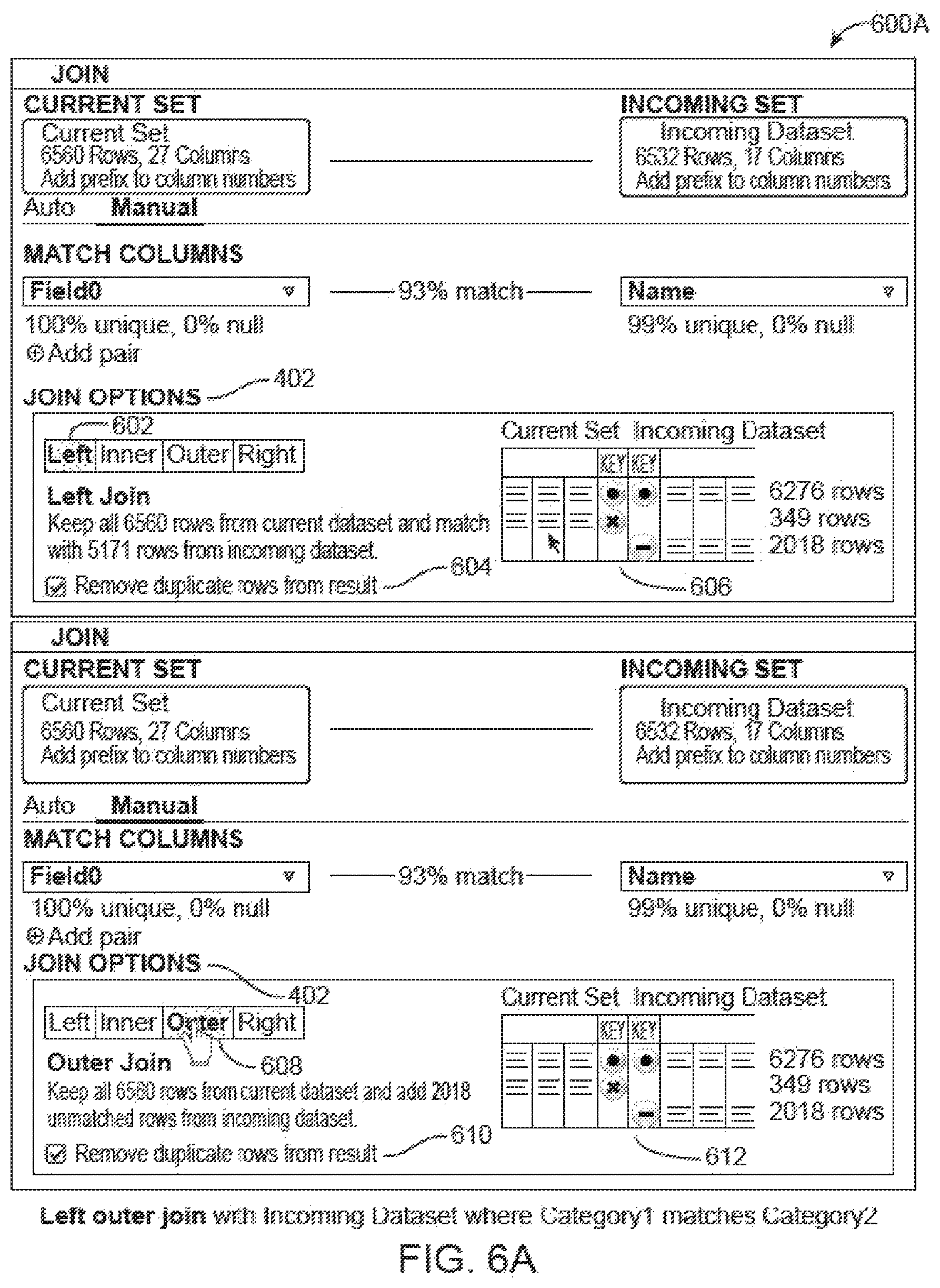
FIG. 6A is a diagram of two screen captures 600A of a graphical user interface configured to display a join operation board of a correspondence area between a first dataset and a second dataset, per some embodiments. The screen capture on the left side of FIG. 6A shows graphical depictions of join operations. A left join button 602 has been selected, causing a left join informational portion 604 to be displayed. Also displayed is a left join graphical table 606 graphically displaying the result of a left join operation. The screen capture on the right side of FIG. 6A shows an outer join button 608 having been selected, causing an outer join information portion 610 and an outer join graphical table 612 to be displayed. FIG. 6B is a diagram of two screen captures 600B of a graphical user interface configured to display a join operation board of a correspondence area between a first dataset and a second dataset, per some embodiments. The screen capture on the left side of FIG. 6B shows a right join button 614 having been selected, causing a right join information portion 616 and a right join graphical table 618 to be displayed. Similarly, the screen capture on the right side of FIG. 6B shows an inner join button 620 having been selected, causing an inner join information portion 622 and an inner join graphical table 624 to be displayed.
Hardware Embodiment
FIG. 7 depicts a block diagram of an example of a computer system 700 upon which any of the embodiments described herein may be implemented. The computer system 700 includes a bus 702 or other communication mechanism for communicating information, one or more hardware processors 704 coupled with bus 702 for processing information. Hardware processor(s) 704 may be, for example, one or more general purpose microprocessors.
The computer system 700 also includes a main memory 706, such as a random access memory (RAM), cache and/or other dynamic storage devices, coupled to bus 702 for storing information and instructions to be executed by processor 704. Main memory 706 also may be used for storing temporary variables or other intermediate information during execution of instructions to be executed by processor 704. Such instructions, when stored in storage media accessible to processor 704, render computer system 700 into a special-purpose machine that is customized to perform the operations specified in the instructions.
The computer system 700 further includes a read only memory (ROM) 708 or other static storage device coupled to bus 702 for storing static information and instructions for processor 704. A storage device 710, such as a magnetic disk, optical disk, or USB thumb drive (Flash drive), etc., is provided and coupled to bus 702 for storing information and instructions.
The computer system 700 may be coupled via bus 702 to a display 712, such as a cathode ray tube (CRT) or LCD display (or touch screen), for displaying information to a computer user. An input device 714, including alphanumeric and other keys, is coupled to bus 702 for communicating information and command selections to processor 704. Another type of user input device is cursor control 716, such as a mouse, a trackball, or cursor direction keys for communicating direction information and command selections to processor 704 and for controlling cursor movement on display 712. This input device typically has two degrees of freedom in two axes, a first axis (e.g., x) and a second axis (e.g., y), that allows the device to specify positions in a plane. In some embodiments, the same direction information and command selections as cursor control may be implemented via receiving touches on a touch screen without a cursor.
The computing system 700 may include a user interface module to implement a GUI that may be stored in a mass storage device as executable software codes that are executed by the computing device(s). This and other modules may include, by way of example, components, such as software components, object-oriented software components, class components and task components, processes, functions, attributes, procedures, subroutines, segments of program code, drivers, firmware, microcode, circuitry, data, databases, data structures, tables, arrays, and variables.
In general, the word "module," as used herein, refers to logic embodied in hardware or firmware, or to a collection of software instructions, possibly having entry and exit points, written in a programming language, such as, for example, Java, C or C++. A software module may be compiled and linked into an executable program, installed in a dynamic link library, or may be written in an interpreted programming language such as, for example, BASIC, Perl, or Python. It will be appreciated that software modules may be callable from other modules or from themselves, and/or may be invoked in response to detected events or interrupts. Software modules configured for execution on computing devices may be provided on a computer readable medium, such as a compact disc, digital video disc, flash drive, magnetic disc, or any other tangible medium, or as a digital download (and may be originally stored in a compressed or installable format that requires installation, decompression or decryption prior to execution). Such software code may be stored, partially or fully, on a memory device of the executing computing device, for execution by the computing device. Software instructions may be embedded in firmware, such as an EPROM. It will be further appreciated that hardware modules may be included of connected logic units, such as gates and flip-flops, and/or may be included of programmable units, such as programmable gate arrays or processors. The modules or computing device functionality described herein are preferably implemented as software modules, but may be represented in hardware or firmware. Generally, the modules described herein refer to logical modules that may be combined with other modules or divided into sub-modules despite their physical organization or storage.
The computer system 700 may implement the techniques described herein using customized hard-wired logic, one or more ASICs or FPGAs, firmware and/or program logic which in combination with the computer system causes or programs computer system 700 to be a special-purpose machine. Per one embodiment, the techniques herein are performed by computer system 700 in response to processor(s) 704 executing one or more sequences of one or more instructions contained in main memory 706. Such instructions may be read into main memory 706 from another storage medium, such as storage device 710. Execution of the sequences of instructions contained in main memory 706 causes processor(s) 704 to perform the process steps described herein. In alternative embodiments, hard-wired circuitry may be used in place of or in combination with software instructions.
The term "non-transitory media," and similar terms, as used herein refers to any media that store data and/or instructions that cause a machine to operate in a specific fashion. Such non-transitory media may include non-volatile media and/or volatile media. Non-volatile media includes, for example, optical or magnetic disks, such as storage device 710. Volatile media includes dynamic memory, such as main memory 706. Common forms of non-transitory media include, for example, a floppy disk, a flexible disk, hard disk, solid state drive, magnetic tape, or any other magnetic data storage medium, a CD-ROM, any other optical data storage medium, any physical medium with patterns of holes, a RAM, a PROM, and EPROM, a FLASH-EPROM, NVRAM, any other memory chip or cartridge, and networked versions of the same.
Non-transitory media is distinct from but may be used in conjunction with transmission media. Transmission media participates in transferring information between non-transitory media. For example, transmission media includes coaxial cables, copper wire and fiber optics, including the wires that include bus 702. Transmission media can also take the form of acoustic or light waves, such as those generated during radio-wave and infra-red data communications.
Various forms of media may be involved in carrying one or more sequences of one or more instructions to processor 704 for execution. For example, the instructions may initially be carried on a magnetic disk or solid state drive of a remote computer. The remote computer can load the instructions into its dynamic memory and send the instructions over a telephone line using a modem. A modem local to computer system 700 can receive the data on the telephone line and use an infra-red transmitter to convert the data to an infra-red signal. An infra-red detector can receive the data carried in the infra-red signal and appropriate circuitry can place the data on bus 702. Bus 702 carries the data to main memory 706, from which processor 704 retrieves and executes the instructions. The instructions received by main memory 706 may retrieves and executes the instructions. The instructions received by main memory 706 may optionally be stored on storage device 710 either before or after execution by processor 704.
The computer system 700 also includes a communication interface 718 coupled to bus 702. Communication interface 718 provides a two-way data communication coupling to one or more network links that are connected to one or more local networks. For example, communication interface 718 may be an integrated services digital network (ISDN) card, cable modem, satellite modem, or a modem to provide a data communication connection to a corresponding type of telephone line. As another example, communication interface 718 may be a local area network (LAN) card to provide a data communication connection to a compatible LAN (or WAN component to communicated with a WAN). Wireless links may also be implemented. In any such embodiment, communication interface 718 sends and receives electrical, electromagnetic or optical signals that carry digital data streams representing various types of information.
A network link typically provides data communication through one or more networks to other data devices. For example, a network link may provide a connection through local network to a host computer or to data equipment operated by an Internet Service Provider (ISP). The ISP in turn provides data communication services through the world wide packet data communication network now commonly referred to as the "Internet". Local network and Internet both use electrical, electromagnetic or optical signals that carry digital data streams. The signals through the various networks and the signals on network link and through communication interface 718, which carry the digital data to and from computer system 700, are example forms of transmission media.
The computer system 700 can send messages and receive data, including program code, through the network(s), network link and communication interface 718. In the Internet example, a server might transmit a requested code for an application program through the Internet, the ISP, the local network and the communication interface 718.
The received code may be executed by processor 704 as it is received, and/or stored in storage device 710, or other non-volatile storage for later execution.
Engines, Components, and Logic
Certain embodiments are described herein as including logic or a number of components, engines, or mechanisms. Engines may constitute either software engines (e.g., code embodied on a machine-readable medium) or hardware engines. A "hardware engine" is a tangible unit capable of performing certain operations and may be configured or arranged in a certain physical manner. In various example embodiments, one or more computer systems (e.g., a standalone computer system, a client computer system, or a server computer system) or one or more hardware engines of a computer system (e.g., a processor or a group of processors) may be configured by software (e.g., an application or application portion) as a hardware engine that operates to perform certain operations as described herein.
In some embodiments, a hardware engine may be implemented mechanically, electronically, or any suitable combination thereof. For example, a hardware engine may include dedicated circuitry or logic that is permanently configured to perform certain operations. For example, a hardware engine may be a special-purpose processor, such as a Field-Programmable Gate Array (FPGA) or an Application Specific Integrated Circuit (ASIC). A hardware engine may also include programmable logic or circuitry that is temporarily configured by software to perform certain operations. For example, a hardware engine may include software executed by a general-purpose processor or other programmable processor. Once configured by such software, hardware engines become specific machines (or specific components of a machine) uniquely tailored to perform the configured functions and are no longer general-purpose processors. It will be appreciated that the decision to implement a hardware engine mechanically, in dedicated and permanently configured circuitry, or in temporarily configured circuitry (e.g., configured by software) may be driven by cost and time considerations.
Accordingly, the phrase "hardware engine" should be understood to encompass a tangible entity, be that an entity that is physically constructed, permanently configured (e.g., hardwired), or temporarily configured (e.g., programmed) to operate in a certain manner or to perform certain operations described herein. As used herein, "hardware-implemented engine" refers to a hardware engine. Considering embodiments in which hardware engines are temporarily configured (e.g., programmed), each of the hardware engines need not be configured or instantiated at any one instance in time. For example, where a hardware engine includes a general-purpose processor configured by software to become a special-purpose processor, the general-purpose processor may be configured as respectively different special-purpose processors (e.g., comprising different hardware engines) at different times. Software accordingly configures a particular processor or processors, for example, to constitute a particular hardware engine at one instance of time and to constitute a different hardware engine at a different instance of time.
Hardware engines can provide information to, and receive information from, other hardware engines. Accordingly, the described hardware engines may be regarded as being communicatively coupled. Where multiple hardware engines exist contemporaneously, communications may be achieved through signal transmission (e.g., over appropriate circuits and buses) between or among two or more of the hardware engines. In embodiments in which multiple hardware engines are configured or instantiated at different times, communications between such hardware engines may be achieved, for example, through the storage and retrieval of information in memory structures to which the multiple hardware engines have access. For example, one hardware engine may perform an operation and store the output of that operation in a memory device to which it is communicatively coupled. A further hardware engine may then, at a later time, access the memory device to retrieve and process the stored output. Hardware engines may also initiate communications with input or output devices, and can operate on a resource (e.g., a collection of information).
The various operations of example methods described herein may be performed, at least partially, by one or more processors that are temporarily configured (e.g., by software) or permanently configured to perform the relevant operations. Whether temporarily or permanently configured, such processors may constitute processor-implemented engines that operate to perform one or more operations or functions described herein. As used herein, "processor-implemented engine" refers to a hardware engine implemented using one or more processors.
Similarly, the methods described herein may be at least partially processor-implemented, with a particular processor or processors being an example of hardware. For example, at least some of the operations of a method may be performed by one or more processors or processor-implemented engines. Moreover, the one or more processors may also operate to support performance of the relevant operations in a "cloud computing" environment or as a "software as a service" (SaaS). For example, at least some of the operations may be performed by a group of computers (as examples of machines including processors), with these operations being accessible via a network (e.g., the Internet) and via one or more appropriate interfaces (e.g., an Application Program Interface (API)).
The performance of certain of the operations may be distributed among the processors, not only residing within a single machine, but deployed across a number of machines. In some example embodiments, the processors or processor-implemented engines may be located in a single geographic location (e.g., within a home environment, an office environment, or a server farm). In other example embodiments, the processors or processor-implemented engines may be distributed across a number of geographic locations.
Language
Throughout this specification, plural instances may implement components, operations, or structures described as a single instance. Although individual operations of one or more methods are illustrated and described as separate operations, one or more of the individual operations may be performed concurrently, and nothing requires that the operations be performed in the order illustrated. Structures and functionality presented as separate components in example configurations may be implemented as a combined structure or component. Similarly, structures and functionality presented as a single component may be implemented as separate components. These and other variations, modifications, additions, and improvements fall within the scope of the subject matter herein.
Although an overview of the subject matter has been described with reference to specific example embodiments, various modifications and changes may be made to these embodiments without departing from the broader scope of embodiments of the present disclosure. Such embodiments of the subject matter may be referred to herein, individually or collectively, by the term "invention" merely for convenience and without intending to voluntarily limit the scope of this application to any single disclosure or concept if more than one is, in fact, disclosed.
The embodiments illustrated herein are described in sufficient detail to enable those skilled in the art to practice the teachings disclosed. Other embodiments may be used and derived therefrom, such that structural and logical substitutions and changes may be made without departing from the scope of this disclosure. The Detailed Description, therefore, is not to be taken in a limiting sense, and the scope of various embodiments is defined only by the appended claims, along with the full range of equivalents to which such claims are entitled.
It will be appreciated that an "engine," "system," "datastore," and/or "database" may include software, hardware, firmware, and/or circuitry. In one example, one or more software programs comprising instructions capable of being executable by a processor may perform one or more of the functions of the engines, datastores, databases, or systems described herein. In another example, circuitry may perform the same or similar functions. Alternative embodiments may include more, less, or functionally equivalent engines, systems, datastores, or databases, and still be within the scope of present embodiments. For example, the functionality of the various systems, engines, datastores, and/or databases may be combined or divided differently.
The datastores described herein may be any suitable structure (e.g., an active database, a relational database, a self-referential database, a table, a matrix, an array, a flat file, a documented-oriented storage system, a non-relational No-SQL system, and the like), and may be cloud-based or otherwise.
As used herein, the term "or" may be construed in either an inclusive or exclusive sense. Moreover, plural instances may be provided for resources, operations, or structures described herein as a single instance. Additionally, boundaries between various resources, operations, engines, engines, and data stores are somewhat arbitrary, and particular operations are illustrated in a context of specific illustrative configurations. Other allocations of functionality are envisioned and may fall within a scope of various embodiments of the present disclosure. In general, structures and functionality presented as separate resources in the example configurations may be implemented as a combined structure or resource. Similarly, structures and functionality presented as a single resource may be implemented as separate resources. These and other variations, modifications, additions, and improvements fall within a scope of embodiments of the present disclosure as represented by the appended claims. The specification and drawings are, accordingly, to be regarded in an illustrative rather than a restrictive sense.
Each of the processes, methods, and algorithms described in the preceding sections may be embodied in, and fully or partially automated by, code modules executed by one or more computer systems or computer processors comprising computer hardware. The processes and algorithms may be implemented partially or wholly in application-specific circuitry.
The various features and processes described above may be used independently of one another, or may be combined in various ways. All possible combinations and sub-combinations are intended to fall within the scope of this disclosure. In addition, certain method or process blocks may be omitted in some embodiments. The methods and processes described herein are also not limited to any particular sequence, and the blocks or states relating thereto can be performed in other sequences that are appropriate. For example, described blocks or states may be performed in an order other than that specifically disclosed, or multiple blocks or states may be combined in a single block or state. The example blocks or states may be performed in serial, in parallel, or in some other manner. Blocks or states may be added to or removed from the disclosed example embodiments. The example systems and components described herein may be configured differently than described. For example, elements may be added to, removed from, or rearranged compared to the disclosed example embodiments.
Conditional language, such as, among others, "can," "could," "might," or "may," unless specifically stated otherwise, or otherwise understood within the context as used, is generally intended to convey that certain embodiments include, while other embodiments do not include, certain features, elements and/or steps. Thus, such conditional language is not generally intended to imply that features, elements and/or steps are in any way required for one or more embodiments or that one or more embodiments necessarily include logic for deciding, with or without user input or prompting, whether these features, elements and/or steps are included or are to be performed in any particular embodiment.
Any process descriptions, elements, or blocks in the flow diagrams described herein and/or depicted in the attached figures should be understood as potentially representing modules, segments, or portions of code which include one or more executable instructions for implementing specific logical functions or steps in the process. Alternate embodiments are included within the scope of the embodiments described herein in which elements or functions may be deleted, executed out of order from that shown or discussed, including substantially concurrently or in reverse order, depending on the functionality involved, as would be understood by those skilled in the art.
It should be emphasized that many variations and modifications may be made to the above-described embodiments, the elements of which are to be understood as being among other acceptable examples. All such modifications and variations are intended to be included herein within the scope of this disclosure. The foregoing description details certain embodiments of the invention. It will be appreciated, however, that no matter how detailed the foregoing appears in text, the invention can be practiced in many ways. As is also stated above, it should be noted that the use of particular terminology when describing certain features or aspects of the invention should not be taken to imply that the terminology is being re-defined herein to be restricted to including any specific characteristics of the features or aspects of the invention with which that terminology is associated. The scope of the invention should therefore be construed in accordance with the appended claims and any equivalents thereof.
* * * * *
References
-
atlchris.com/191/grabup
-
subhub.com/articles/free-screen-capture-software
-
jetscreenshot.com
-
kwout.com
-
msdn.microsoft.com/en-us/library/aa767914.aspx
-
-
blog.nitropdf.com/2008/03/04/trick-how-to-capture-a-screenshot-as-pdf-annotate-it-then-share
-
online-tech-tips.com/free-software-downloads/share-files-folders-screenshots
-
oreilly.com/digitalmedia/2006/01/01/mac-os-x-screenshot-secrets.htmlpublishedJan
-
mashable.com/2007/08/24/web-screenshots
-
download.techsmith.com/snagit/docs/onlinehelp/enu/snagit_help.pdf
-
tuaw.com/2008/05/05/tuaw-faceoff-screenshot-apps-on-the-firing-line
D00000
D00001
D00002
D00003
D00004
D00005
D00006
D00007
D00008
XML
uspto.report is an independent third-party trademark research tool that is not affiliated, endorsed, or sponsored by the United States Patent and Trademark Office (USPTO) or any other governmental organization. The information provided by uspto.report is based on publicly available data at the time of writing and is intended for informational purposes only.
While we strive to provide accurate and up-to-date information, we do not guarantee the accuracy, completeness, reliability, or suitability of the information displayed on this site. The use of this site is at your own risk. Any reliance you place on such information is therefore strictly at your own risk.
All official trademark data, including owner information, should be verified by visiting the official USPTO website at www.uspto.gov. This site is not intended to replace professional legal advice and should not be used as a substitute for consulting with a legal professional who is knowledgeable about trademark law.