Systems and methods for identifying a diameter of a sampling point
Miheli , et al. March 9, 2
U.S. patent number 10,942,021 [Application Number 16/000,194] was granted by the patent office on 2021-03-09 for systems and methods for identifying a diameter of a sampling point. This patent grant is currently assigned to Honeywell International Inc.. The grantee listed for this patent is Honeywell International Inc.. Invention is credited to Marco Causero, Jochen Hahn, Mauro Miheli.

| United States Patent | 10,942,021 |
| Miheli , et al. | March 9, 2021 |
Systems and methods for identifying a diameter of a sampling point
Abstract
Systems and methods for identifying a diameter of a sampling point on a pipe within an aspirated smoke detector system are provided. Such systems and methods may include a clip having a body portion configured to circumscribe a surface of a circumference of a pipe, an opening defined by, extending through, and surrounded by the body portion, and size indicating indicia affixed to the body portion that visually identifies a size of the opening.
| Inventors: | Miheli; Mauro (Trieste, IT), Causero; Marco (Trieste, IT), Hahn; Jochen (Moenchengladbach, DE) | ||||||||||
|---|---|---|---|---|---|---|---|---|---|---|---|
| Applicant: |
|
||||||||||
| Assignee: | Honeywell International Inc.
(Charlotte, NC) |
||||||||||
| Family ID: | 1000005409888 | ||||||||||
| Appl. No.: | 16/000,194 | ||||||||||
| Filed: | June 5, 2018 |
Prior Publication Data
| Document Identifier | Publication Date | |
|---|---|---|
| US 20190368854 A1 | Dec 5, 2019 | |
| Current U.S. Class: | 1/1 |
| Current CPC Class: | G01B 5/12 (20130101) |
| Current International Class: | G01B 5/12 (20060101) |
| Field of Search: | ;33/555.1 |
References Cited [Referenced By]
U.S. Patent Documents
| 6143090 | November 2000 | Lietz |
| 6708782 | March 2004 | Turney |
| 2004/0074100 | April 2004 | Polk, Jr. |
| 2007/0008157 | January 2007 | Siemens et al. |
| 2009/0267345 | October 2009 | Choi |
| 2011/0017026 | January 2011 | Chang |
| 2012/0242080 | September 2012 | Nezu |
| 2015/0379846 | December 2015 | Bressanutti |
| 2016/0115781 | April 2016 | Douglas |
| 2019/0358762 | November 2019 | Lause |
| 2020/0080829 | March 2020 | Swenson, Jr. |
| 101421762 | Apr 2009 | CN | |||
| 104200605 | Dec 2014 | CN | |||
| 19605842 | Apr 1997 | DE | |||
| 29905039 | Jun 1999 | DE | |||
Other References
|
Aspirating smoke detectors, AMX4004, .COPYRGT. Viking GmbH & Co. KG, www.viking-emea.com, Oct. 31, 2017. cited by applicant . Smoke Extraction System--Titanus PRO Sens, BOSCH Security Systems, www.boschsecuritysystems.com, Oct. 31, 2017. cited by applicant . Extended Search Report from related European Patent Application No. 19177747, dated Oct. 23, 2019, 8 pages. cited by applicant . Chinese Office Action & Search Report for related Chinese Application No. 201910471533.0, dated Oct. 12, 2020 (7 pgs) & English Translation of Search Report (3 pgs); Total: 10 pgs. cited by applicant. |
Primary Examiner: Bennett; George B
Attorney, Agent or Firm: Brooks, Cameron & Huebsch, PLLC
Claims
What is claimed is:
1. A clip comprising: a body portion configured to circumscribe a surface of a circumference of a pipe of an aspirated smoke detector system including at least one pre-drilled hole; an opening defined by, extending through, and surrounded by the body portion; and size indicating indicia affixed to the body portion, wherein the size indicating indicia visually identifies a first size of the opening, second size indicating indicia affixed to the body portion, wherein the second size indicating indicia visually identifies intermediate dimensions of the first size of the opening, and wherein the opening provides a flow channel into and out of the at least one pre-drilled hole.
2. The clip of claim 1 wherein the body portion is configured to tension grip the surface of the circumference of the pipe.
3. The clip of claim 1 wherein the body portion is configured to friction grip the surface of the circumference of the pipe.
4. The clip of claim 1 wherein the size indicating indicia is selected from a reference table of a plurality of size indicating indicia and a plurality of sizes.
5. The clip of claim 1 wherein the size indicating indicia includes a color representative of the size of the opening.
6. The clip of claim 1 wherein the size indicating indicia includes a symbol representative of the first size of the opening.
7. The clip of claim 1 wherein the size indicating indicia includes a combination of a symbol and a color representative of the first size of the opening.
8. The clip of claim 1 wherein the first size includes a diameter.
9. The clip of claim 1 wherein the opening and the body portion alter a second size of the pre-drilled hole.
10. A system comprising: a pipe of an aspirated smoke detector system including at least one pre-drilled hole; and a clip that includes a body portion circumscribing a surface of a circumference of the pipe, an opening defined by, extending through, and surrounded by the body portion, a first size indicating indicia affixed to the body portion that visually identifies a first size of the opening, and second size indicating indicia affixed to the body portion, wherein the second size indicating indicia visually identifies intermediate dimensions of the first size of the opening, and wherein the opening provides a flow channel into and out of the predrilled hole.
11. The system of claim 10 wherein the body portion tension grips the surface of the circumference of the pipe.
12. The system of claim 10 wherein the body portion friction grips the surface of the circumference of the pipe.
13. The system of claim 10 wherein the size indicating indicia is selected from a reference table of a plurality of size indicating indicia and a plurality of sizes.
14. The system of claim 10 wherein the size indicating indicia includes a color representative of the first size of the opening.
15. The system of claim 10 wherein the size indicating indicia includes a symbol representative of the first size of the opening.
16. The system of claim 10 wherein the size indicating indicia includes a combination of a symbol and a unique representative of the first size of the opening.
17. The system of claim 10 wherein the first size includes a diameter.
18. The system of claim 10 wherein the first size matches a second size of the pre-drilled hole.
19. The system of claim 10 wherein the opening and the body portion alter a second size of the pre-drilled hole.
Description
FIELD
The present invention relates generally to an aspirated smoke detector system. More particularly, the present invention relates to systems and methods for creating and identifying diameters of sampling points on a plurality of pipes within the aspirated smoke detector system.
BACKGROUND
A known aspirated smoke detector system requires a distributed pipe network with multiple sampling points. The sampling points may include holes having diameters of different sizes to be drilled into pipes of the pipe network to ensure proper functioning of the aspirated smoke detector system. However, the pipes are often deployed directly underneath a ceiling, which can visually obscure the pipes from an installer attempting to view or identify a size of a hole.
In view of the above, there is a continuing, ongoing need for improved systems and methods.
BRIEF DESCRIPTION OF THE DRAWINGS
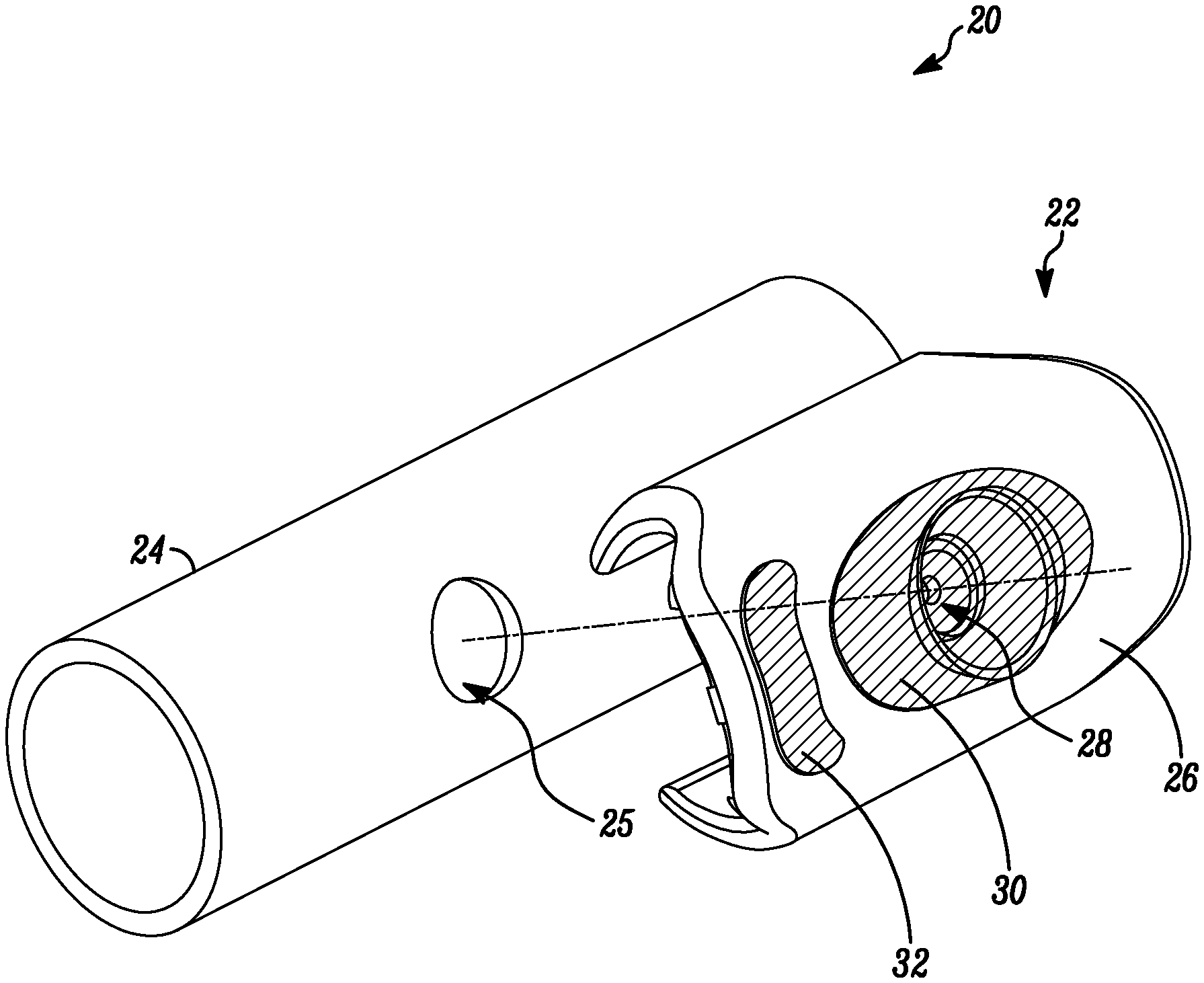
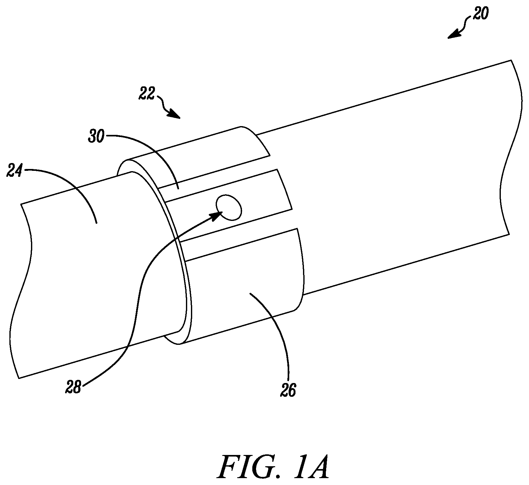
FIG. 1A is a perspective view of a clip and a pipe in accordance with disclosed embodiments; and
FIG. 1B is a perspective view of a clip and a pipe in accordance with disclosed embodiments.
DETAILED DESCRIPTION
While this invention is susceptible of an embodiment in many different forms, there are shown in the drawings and will be described herein in detail specific embodiments thereof with the understanding that the present disclosure is to be considered as an exemplification of the principles of the invention. It is not intended to limit the invention to the specific illustrated embodiments.
Embodiments disclosed herein may include systems and methods for identifying a diameter of a sampling point on a pipe within an aspirated smoke detector system. For example, systems and methods disclosed herein may include a clip for circumscribing at least a portion of a circumference of the pipe at a location along a length of the pipe at which a standard size hole (sampling point) in the pipe is located. In some embodiments, the standard size hole can include a diameter of 10 mm. Additionally or alternatively, the clip can alter the standard hole to a different diameter and a size indicating indicia can identify the altered hole diameter.
In accordance with disclosed embodiments, the clip may include a body portion configured to grip or affix to a surface of the circumference of the pipe, an opening defined by, extending through, and surrounded by the body portion, and size indicating indicia on at least a portion of the body portion. In some embodiments, the size indicating indicia may visually identify a size of the opening, such as a diameter thereof, and, therefore, a size (diameter) of the hole in the pipe at the location of the clip on the pipe. That is, in some embodiments, the size of the opening in the clip may match the size of the hole in the pipe.
In some embodiments, the body portion of the clip may tension grip the pipe. Additionally or alternatively, in some embodiments, the clip may friction grip the pipe. Additionally or alternatively, the clip may be coupled to the pipe in any manner as would be known and understood by one of ordinary skill in the art.
In some embodiments, the size indicating indicia may include a color representative of the size of the opening in the clip and, therefore, the size of the hole in the pipe at the location of the clip on the pipe. For example, the color red can represent the size of 1 inch, and the color blue can represent the size of 2 inches. In some embodiments a second size indicating indicia can be included to indicate intermediate dimensions of the opening in the clip. For example, the first or main size indicating indicia can be blue to indicate a primary dimension of 6 mm and the second size indicating indicia on a tab of the clip can be blue to indicate the opening is an additional 0.5 mm in diameter for a total diameter or 6.5 mm. Additionally or alternatively, in some embodiments, the size indicating indicia may include a symbol representative of the size of the opening in the clip and, therefore, the size of the hole in the pipe at the location of the clip on the pipe. Additionally or alternatively, in some embodiments, the size indicating indicia may include a combination of the symbol and the color, such as the symbol having the color, representative of the size of the opening in the clip and, therefore, the size of the hole in the pipe at the location of the clip on the pipe.
In some embodiments, the size indicating indicia on the clip may be selected from and/or compared to a reference table that identifies the size of the opening in the clip represented by the size indicating indicia. In some embodiments, the table may include separate entries for a first size indicating indicia and a second size indicating indicia used to indicate intermediate measurements.
FIG. 1A and FIG. 1B are a perspective view of a system 20 in accordance with disclosed embodiments. As seen, the system 20 may include a clip 22 coupled to a pipe 24. The clip 22 may include a body portion 26 configured to grip a surface of a circumference of the pipe 24, an opening 28 defined by, extending through, and surrounded by the body portion 26, and size indicating indicia 30 on a portion of the body portion 26 that visually identifies a size of the opening 28 and, therefore, a size of at least one pre-drilled hole 25 in the pipe 24 existing at a location of the clip 22 on the pipe 24. The opening 28 can provide a flow channel into and out of the at least one pre-drilled hole 25. In some embodiments, the body portion 26 and the opening 28 can alter a size of the pre-drilled hole 25. For example, the body portion 26 and the opening 28 can reduce the diameter of the pre-drilled hole 25. In some embodiments, the clip 22 can include a tab 32 which can include a second size indicating indicia used to document intermediate sizes of the opening 28.
From the foregoing, it will be observed that numerous variations and modifications may be effected without departing from the spirit and scope of the invention. It is to be understood that no limitation with respect to the specific system or method described herein is intended or should be inferred. It is, of course, intended to cover all such modifications as fall within the spirit and scope of the invention.
* * * * *
References
D00000
D00001
D00002
XML
uspto.report is an independent third-party trademark research tool that is not affiliated, endorsed, or sponsored by the United States Patent and Trademark Office (USPTO) or any other governmental organization. The information provided by uspto.report is based on publicly available data at the time of writing and is intended for informational purposes only.
While we strive to provide accurate and up-to-date information, we do not guarantee the accuracy, completeness, reliability, or suitability of the information displayed on this site. The use of this site is at your own risk. Any reliance you place on such information is therefore strictly at your own risk.
All official trademark data, including owner information, should be verified by visiting the official USPTO website at www.uspto.gov. This site is not intended to replace professional legal advice and should not be used as a substitute for consulting with a legal professional who is knowledgeable about trademark law.