Sealing and cover strip for the B-pillar of a passenger vehicle
Ertl March 9, 2
U.S. patent number 10,940,745 [Application Number 16/081,227] was granted by the patent office on 2021-03-09 for sealing and cover strip for the b-pillar of a passenger vehicle. This patent grant is currently assigned to CADEA GESELLSCHAFT FUR ANWENDUNG UND REALISIERUNG COMPUTERUNTERSTUTZTER SYSTEME MBH. The grantee listed for this patent is Cadea Gesellschaft fur Anwendung und Realisierung computerunterstutzter Systeme mbH. Invention is credited to Harald Ertl.
| United States Patent | 10,940,745 |
| Ertl | March 9, 2021 |
Sealing and cover strip for the B-pillar of a passenger vehicle
Abstract
The invention comprises a sealing and cover strip (8) for the B-pillar (7) of a passenger vehicle (1) comprising a support cover (10) and a decorative cover (9), each of which has a sealing half of a sealing profile for a lowerable side window on at least one of their common longitudinal sides. The present invention improves a sealing and cover strip (8) in such a way that the assembly effort during production of the vehicle is reduced and the optical appearance is improved. This follows from the fact that each sealing profile (11, 12) comprises two sealing halves (13, 14 and 13', 14'), respective halves (13, 13') being integral with the decorative cover (9), and respective halves (14, 14') being integral with the support cover (10).
| Inventors: | Ertl; Harald (Eichenau, DE) | ||||||||||
|---|---|---|---|---|---|---|---|---|---|---|---|
| Applicant: |
|
||||||||||
| Assignee: | CADEA GESELLSCHAFT FUR ANWENDUNG
UND REALISIERUNG COMPUTERUNTERSTUTZTER SYSTEME MBH (Eichenau,
DE) |
||||||||||
| Family ID: | 1000005408723 | ||||||||||
| Appl. No.: | 16/081,227 | ||||||||||
| Filed: | January 19, 2017 | ||||||||||
| PCT Filed: | January 19, 2017 | ||||||||||
| PCT No.: | PCT/EP2017/051022 | ||||||||||
| 371(c)(1),(2),(4) Date: | August 30, 2018 | ||||||||||
| PCT Pub. No.: | WO2017/148613 | ||||||||||
| PCT Pub. Date: | September 08, 2017 |
Prior Publication Data
| Document Identifier | Publication Date | |
|---|---|---|
| US 20190077239 A1 | Mar 14, 2019 | |
Foreign Application Priority Data
| Mar 4, 2016 [DE] | 10 2016 002 681.2 | |||
| Current U.S. Class: | 1/1 |
| Current CPC Class: | B60J 10/7775 (20160201); B29C 45/14 (20130101); B60J 10/77 (20160201); B60J 10/45 (20160201); B60R 13/04 (20130101); B60J 10/79 (20160201); B29L 2031/302 (20130101) |
| Current International Class: | B60J 10/777 (20160101); B60J 10/77 (20160101); B60J 10/79 (20160101); B60J 10/00 (20160101); B60R 13/04 (20060101); B29C 45/14 (20060101) |
References Cited [Referenced By]
U.S. Patent Documents
| 5027556 | July 1991 | Ginster |
| 5067281 | November 1991 | Dupuy |
| 5092078 | March 1992 | Keys |
| 5174066 | December 1992 | Dupuy |
| 5345718 | September 1994 | Dupuy |
| 5860692 | January 1999 | Nozaki |
| 6103168 | August 2000 | Kelly |
| 6817651 | November 2004 | Carvalho |
| 7434867 | October 2008 | Matthies |
| 7866727 | January 2011 | Fuetterer |
| 8388039 | March 2013 | Gerndorf et al. |
| 2006/0150523 | July 2006 | Matthies |
| 2007/0094933 | May 2007 | Matthies |
| 2009/0001755 | January 2009 | Fuetterer |
| 2009/0267373 | October 2009 | Gerndorf et al. |
| 20304269 | Jun 2003 | DE | |||
| 102004041741 | Jun 2005 | DE | |||
| 1695808 | Aug 2006 | EP | |||
| 2113422 | Nov 2009 | EP | |||
| 3118040 | Jan 2017 | EP | |||
| 2247489 | Mar 1992 | GB | |||
| 2002154323 | May 2002 | JP | |||
| 2006520293 | Sep 2006 | JP | |||
| 200996228 | May 2009 | JP | |||
Other References
|
English translation of International Search Report for international application PCT/EP2017/051022, international filing date of Jan. 19, 2017, dated Apr. 26, 2017, 3 pages. cited by applicant . English Translation of Written Opinion for international application PCT/EP2017/051022, international filing date of Jan. 19, 2017, dated Apr. 26, 2017, 4 pages. cited by applicant . India Examination Report; India Application No. 201817034158; dated Dec. 17, 2019; 6 pages. cited by applicant . Japanese Office Action with English Translation; Japanese Application No. 2018-545488; dated Aug. 14, 2019; 5 pages. cited by applicant. |
Primary Examiner: Menezes; Marcus
Attorney, Agent or Firm: Cantor Colburn LLP
Claims
The invention claimed is:
1. Sealing and cover strip for the B-pillar of a passenger vehicle having a roof column, the sealing and cover strip comprising a decorative cover and a support cover, the decorative cover being configured to face outwardly of the vehicle to thereby provide a visible surface of the sealing and cover strip, the support cover underlying the decorative cover and configured for fastening the sealing and cover strip to the B-pillar of the vehicle, wherein the decorative cover and the support cover cooperate to define respective opposite longitudinal sides of the sealing and cover strip, and a sealing profile for lowerable side windows is disposed on each of the opposite longitudinal sides, characterized in that the sealing profiles each consists of two separate sealing halves which are configured to contact and seal their respective associated lowerable side windows, one respective sealing half of each sealing profile being integral with the decorative cover and the respective other sealing half of each sealing profile being integral with the support cover.
2. Sealing and cover strip according to claim 1, characterized in that one of the sealing halves of the sealing profile is produced by two-component injection molding with the decorative cover to render that sealing half integral with the decorative cover and the other sealing half is produced by two-component injection molding with the support cover to render the other sealing half integral with the support cover.
3. Sealing and cover strip according to claim 1 or claim 2, characterized in that a side of one sealing half is disposed adjacent to the visible surface of the decorative cover and merges into the visible surface of the decorative cover without gaps.
4. Sealing and cover strip according to claim 1 or claim 2, characterized in that the support cover has an upper end which merges into a window edging on the roof column of the passenger vehicle, and corner pieces integral with the support cover are provided at the upper end of the support cover, and wherein the corner pieces are produced by two-component injection molding together with the support cover.
5. Sealing and cover strip according to claim 1 or claim 2, characterized in that the decorative cover has an upper end and a lower end, and end pieces integral with the decorative cover are provided at the upper end and at the lower end, wherein the end pieces are injection-molded integrally with the decorative cover.
6. Sealing and cover strip according to claim 1 or claim 2, characterized in that the decorative cover is bonded to the support cover.
7. Sealing and cover strip according to claim 3, characterized in that the sealing and cover strip comprises two respective ones of the sealing profile, one sealing profile being provided on each of the longitudinal sides.
8. Sealing and cover strip according to claim 3, characterized in that the support cover has an upper end which merges into a window edging on the roof column of the passenger vehicle, and corner pieces integral with the support cover are provided at the upper end of the support cover, and wherein the corner pieces are produced by two-component injection molding together with the support cover.
9. Sealing and cover strip according to claim 1, characterized in that the support cover has an upper end which merges into a window edging on the roof column of the passenger vehicle, wherein cover pieces integral with the support cover are provided at the upper end of the support cover and the corner pieces are produced by two-component injection molding together with the support cover.
10. Sealing and cover strip according to claim 3, characterized in that the decorative cover has an upper end and a lower end, and end pieces integral with the decorative cover are disposed at the upper end and at the lower end, and wherein the end pieces are injection-molded integrally with the decorative cover.
11. Sealing and cover strip according to claim 3, characterized in that the decorative cover is bonded to the support cover.
Description
CROSS-REFERENCE TO RELATED APPLICATIONS
This application is a U.S. national stage application of International Application No. PCT/EP2017/051022, which has an international filing date of 19 Jan. 2017, and which claims priority to German patent application number DE 10 2016 002 681.2, filed 4 Mar. 2016.
BACKGROUND OF THE INVENTION
Field of the Invention
The invention refers to a sealing and cover strip for the B-pillar of a two- or four-door passenger vehicle with frameless doors.
Description of Related Art
The B-pillar of a passenger vehicle is located between the front door and the rear door of a passenger vehicle, or in the case of a coupe between the side window of the front door and the rear movable or fixed side glazing of a passenger vehicle. In vehicles with frameless side windows, the seals are attached directly to the B-pillar. In these cases, the B-pillar usually has a support cover and a decorative cover, which together form a groove on the longitudinal side, which is assigned to a lowerable side window, into which groove a sealing profile is clipped in or inserted. Such a sealing strip is known from DE 10 2004 041 7 41 B3, for example. Inserting or clipping in the seal requires increased assembly effort. In addition, it can happen that, especially in older vehicles, the seals are no longer firmly seated, so that between the decorative strip of the B-pillar and the seal an optically unattractive gap can form which varies in size. The seal itself consists of two profiles and three vulcanized-on corners.
SUMMARY OF THE INVENTION
It is therefore the object of the present invention to design a sealing and cover strip of the type mentioned above in such a way that the assembly effort during manufacture of the vehicle is reduced, the optical appearance and quality are improved and the costs are reduced.
According to the invention, this object is solved by the features of claim 1. The cover now consists of two halves. The decorative cover including molded-on seal and the support cover with molded-on seal are joined to form a single component. The seal is no longer clipped into the groove formed between the support cover and the decorative cover; rather, the seal is divided into two halves, with one half connected to the decorative cover and the other half connected to the support cover. As soon as the support cover and decorative cover are connected, the two halves form a sealing profile which was previously made in one piece.
The respective seal halves of the seal can be connected to the decorative cover and the support cover by two-component injection molding in a particularly simple manner. For this purpose, only one of the mold halves has to be replaced during the injection process in order to inject the second component, here the elastomeric material for the seal.
It is particularly preferred if the side of one half of the seal facing the visible surface of the decorative cover merges into the visible surface of the decorative cover without gaps. If the color of the plastic material for the decorative cover and that of the half seal is chosen appropriately, there is hardly any difference between the seal and the decorative cover on the B-pillar.
An advantageous variant of the invention provides that seals are provided on both longitudinal sides and on the lower side of the support cover and decorative cover. In this way, the window of the rear vehicle door can also be frameless.
The assembly effort can be further reduced if corner pieces are provided at the upper end of the support cover, which merge into the window frame on the roof column of the passenger vehicle, whereby the end pieces are formed, allocated also partly on the support cover and partly on the decorative cover, by two-component injection molding.
In the same way, the seal halves can have end pieces at the lower end which are injection-molded integrally with the cover parts. Thus, all sealing elements as well as end and corner pieces are connected with a total of two parts. In an advantageous way, both parts, i.e. the decorative cover and the support cover, can be substance-to-substance bonded, for example by ultrasonic welding.
BRIEF DESCRIPTION OF THE DRAWINGS
In the following, an embodiment of the invention is explained in more detail on the basis of a drawing.
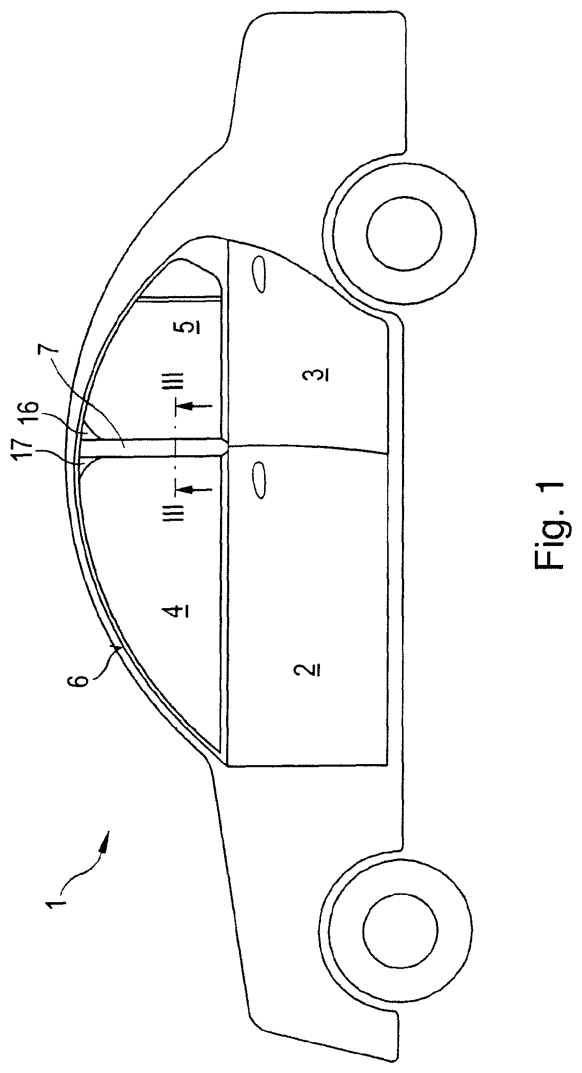
FIG. 1 shows a passenger vehicle with a B-pillar,
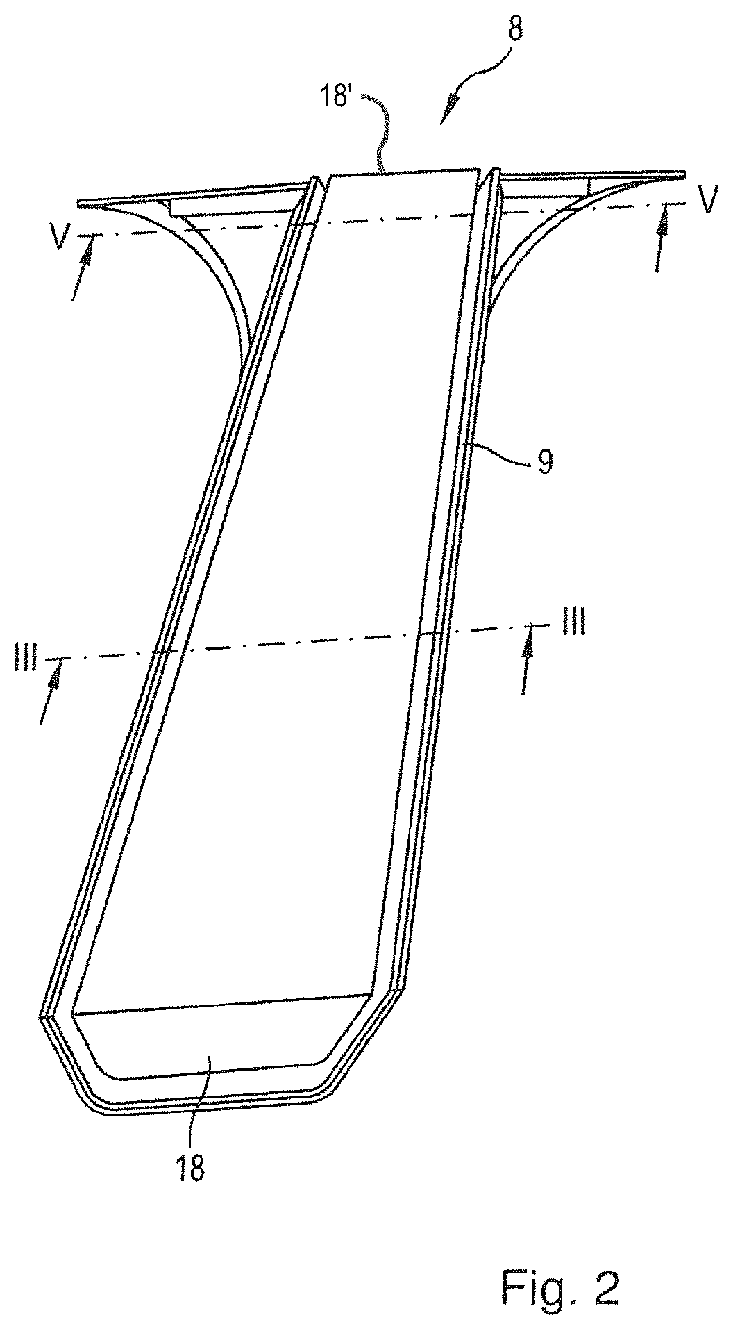
FIG. 2 shows a sealing and cover strip for a B-pillar according to FIG. 1,
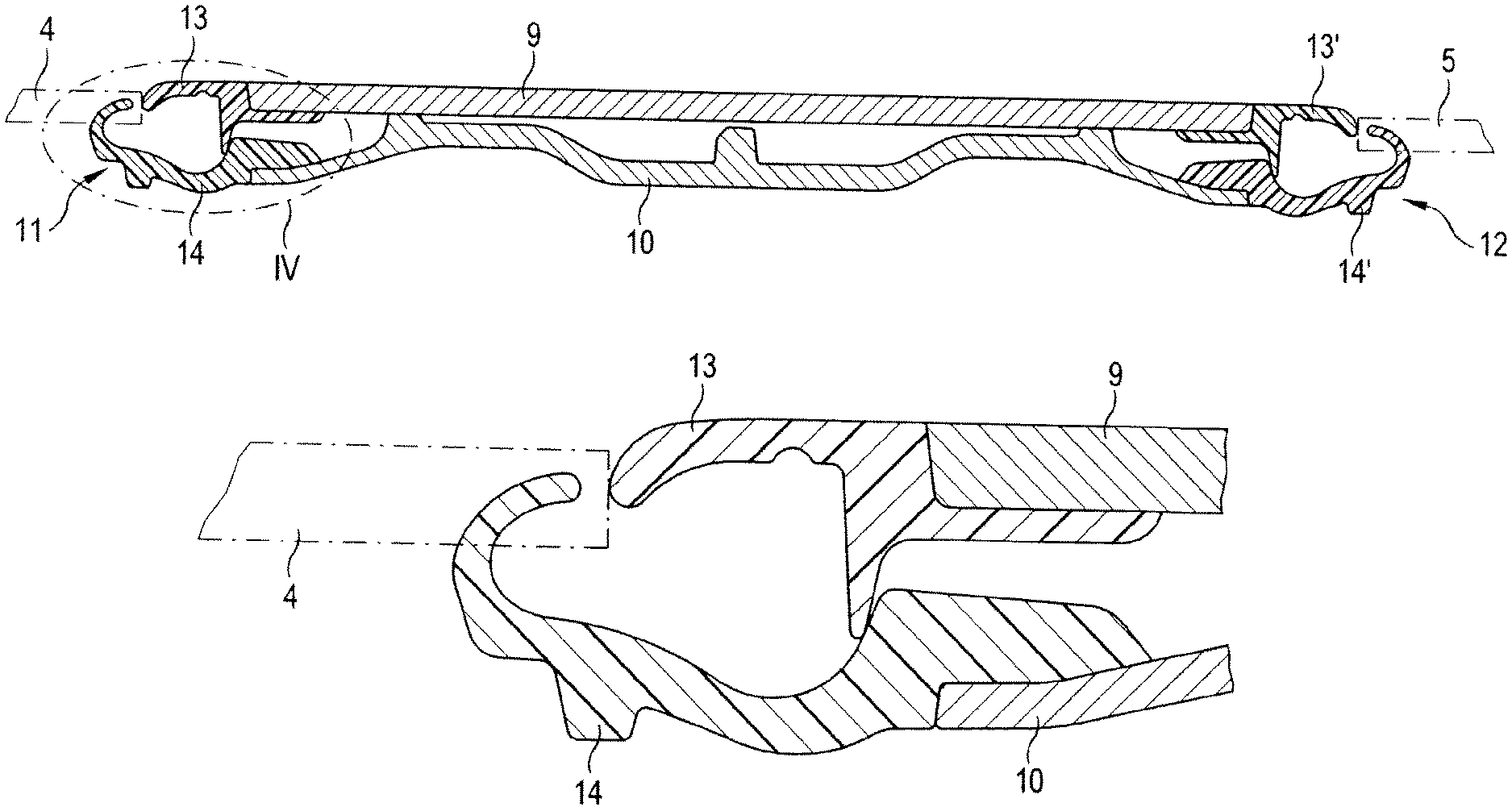
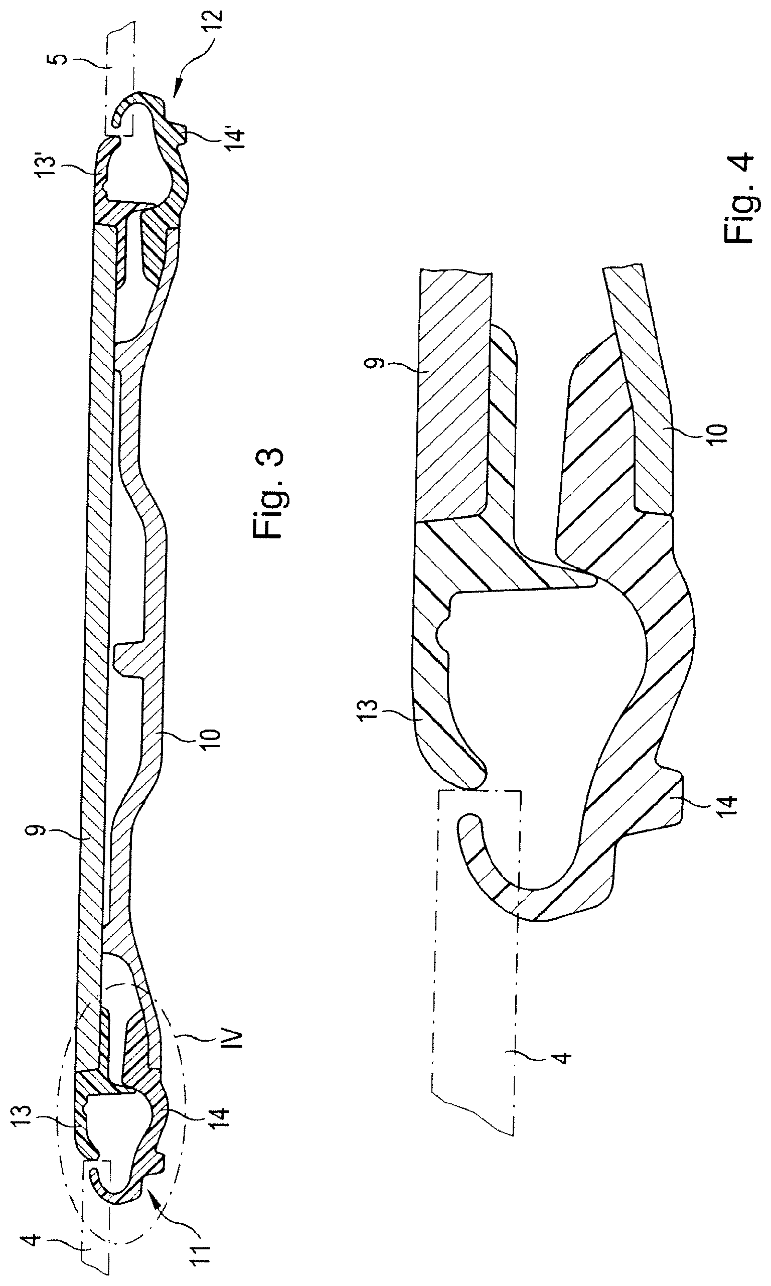
FIG. 3 shows a sectional view along the line III-Ill through the sealing and cover strip according to FIG. 2,
FIG. 4 shows an enlarged detailed view of the detail IV from FIG. 3, and
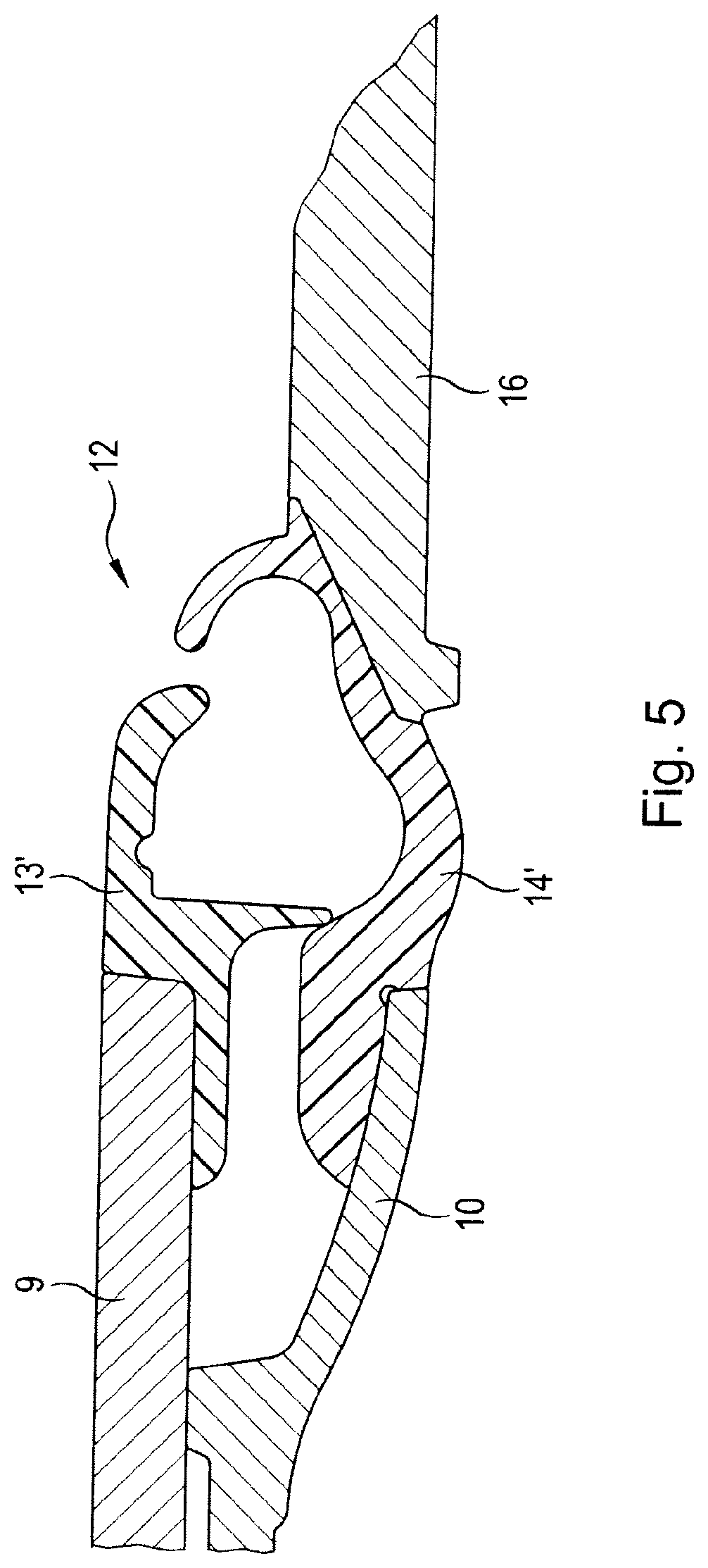
FIG. 5 shows in an enlarged detailed view a sectional view along Line V-V line through the sealing and cover strip according to FIG. 2.
DETAILED DESCRIPTION OF THE INVENTION AND SPECIFIC EMBODIMENTS THEREOF
The passenger vehicle shown in FIG. 1 is a vehicle which has a frameless window 4 and 5 both in the area of the front door 2 and in the area of the rear door 3. In the area of the roof column 6 and the door shafts, the windows 4 and 5 are sealed by known window edgings. In the area of the B-pillar 7, a sealing and cover strip 8 (FIG. 2) is provided for this purpose, which is shown in more detail in FIG. 2. When looking at FIG. 3, the sealing and cover strip 8 are seen to comprise an outer decorative cover 9, which faces the outside of the vehicle, and an underlying support cover 10, with which the sealing and cover strip 8 is fastened to the B-pillar of the vehicle. Seals 11 and 12 are provided for the side windows 4 and 5 on the common longitudinal sides of support cover 10 and decorative cover 9. These seals 11 and 12 each consist of two sealing halves 13 and 14 or 13' and 14', of which one half 13 or 13' is connected to the decorative cover and the other half 14 or 14' is connected to the support cover 10.
Corner pieces 16 and 17 are provided at the upper end of the sealing and cover strip 8, which form the transition from the sealing and cover strip 8 to the window edging 6 on the upper roof column. These corner pieces 16 and 17, as well as the sealing halves 14 and 14', are manufactured integrally with the support cover 10 by two-component injection molding. In the same way, the sealing halves 13 and 13' are connected integrally with the decorative cover 9, also by two-component injection molding.
In a similar manner, end pieces 18, 18' (FIG. 2) covering the door shaft are also molded onto the decorative cover 9 and the support cover 10. The decorative cover 9 and the support cover 10 are joined by ultrasonic or laser welding. Alternatively, both components can also be glued together.
The mode of action and function of the invention is explained in more detail below.
By separating the sealing profiles 11 and 12 into individual halves 13 and 14 or 13' and 14' as best seen in FIG. 3, it is possible to produce these individual halves integrally with, respectively, the decorative cover 9 and the support cover 10 by using two-component injection molding. By simply connecting the decorative cover 9 to the support cover 10, sealing profiles 11 and 12 are formed without the sealing profiles having to be subsequently threaded between the support cover and the decorative cover. Another advantage is that all other end and corner pieces 16, 17 and 18 can also be produced integrally with the decorative cover 9 and the support cover 10, so that only the decorative cover 9 has to be connected with the support cover 10 to complete the sealing and cover strip 8. In this way, the manufacturing process, and in particular the assembly of the sealing and cover strip, is significantly simplified. The use of suitable materials, such as friction-optimized, thermoplastic elastomers for the sealing function, means that the time-consuming and cost-intensive assembly processes of the previous system can be dispensed with.
* * * * *
D00000
D00001
D00002
D00003
D00004
XML
uspto.report is an independent third-party trademark research tool that is not affiliated, endorsed, or sponsored by the United States Patent and Trademark Office (USPTO) or any other governmental organization. The information provided by uspto.report is based on publicly available data at the time of writing and is intended for informational purposes only.
While we strive to provide accurate and up-to-date information, we do not guarantee the accuracy, completeness, reliability, or suitability of the information displayed on this site. The use of this site is at your own risk. Any reliance you place on such information is therefore strictly at your own risk.
All official trademark data, including owner information, should be verified by visiting the official USPTO website at www.uspto.gov. This site is not intended to replace professional legal advice and should not be used as a substitute for consulting with a legal professional who is knowledgeable about trademark law.