Thermal air flow meter
Ogata , et al. February 23, 2
U.S. patent number 10,928,232 [Application Number 15/519,452] was granted by the patent office on 2021-02-23 for thermal air flow meter. This patent grant is currently assigned to Hitachi Automotive Systems, Ltd.. The grantee listed for this patent is Hitachi Automotive Systems, Ltd.. Invention is credited to Hiroaki Hoshika, Norio Ishitsuka, Masatoshi Ogata, Takayuki Yogo.


View All Diagrams
| United States Patent | 10,928,232 |
| Ogata , et al. | February 23, 2021 |
Thermal air flow meter
Abstract
The purpose is to improve the measurement accuracy of a thermal air flow meter. The device has: an auxiliary passage for entraining a portion of a fluid being measured; a sensor chip arranged in the auxiliary passage, for measuring the flow rate of the fluid being measured; an electronic component having an internal resistor, for converting the fluid flow rate detected by the sensor chip to an electrical signal; and a substrate on which the sensor chip and the electronic component are mounted. The substrate is covered by a filler material, on the surface of which the electronic component is mounted.
| Inventors: | Ogata; Masatoshi (Tokyo, JP), Ishitsuka; Norio (Tokyo, JP), Yogo; Takayuki (Ibaraki, JP), Hoshika; Hiroaki (Ibaraki, JP) | ||||||||||
|---|---|---|---|---|---|---|---|---|---|---|---|
| Applicant: |
|
||||||||||
| Assignee: | Hitachi Automotive Systems,
Ltd. (Hitachinaka, JP) |
||||||||||
| Family ID: | 55908895 | ||||||||||
| Appl. No.: | 15/519,452 | ||||||||||
| Filed: | September 24, 2015 | ||||||||||
| PCT Filed: | September 24, 2015 | ||||||||||
| PCT No.: | PCT/JP2015/076833 | ||||||||||
| 371(c)(1),(2),(4) Date: | April 14, 2017 | ||||||||||
| PCT Pub. No.: | WO2016/072166 | ||||||||||
| PCT Pub. Date: | May 12, 2016 |
Prior Publication Data
| Document Identifier | Publication Date | |
|---|---|---|
| US 20170241820 A1 | Aug 24, 2017 | |
Foreign Application Priority Data
| Nov 6, 2014 [JP] | JP2014-225706 | |||
| Current U.S. Class: | 1/1 |
| Current CPC Class: | G01F 1/6842 (20130101); G01F 15/02 (20130101); G01F 1/684 (20130101); F02M 35/10386 (20130101); G01F 15/006 (20130101); G01F 1/696 (20130101) |
| Current International Class: | G01F 1/696 (20060101); G01F 15/02 (20060101); G01F 1/684 (20060101); G01F 15/00 (20060101); F02M 35/10 (20060101) |
| Field of Search: | ;73/204.11-204.27 |
References Cited [Referenced By]
U.S. Patent Documents
| 4381668 | May 1983 | Sato et al. |
| 5440924 | August 1995 | Itsuji et al. |
| 6070462 | June 2000 | Igarashi et al. |
| 6516785 | February 2003 | Nakada et al. |
| 6779393 | August 2004 | Muller et al. |
| 2001/0023983 | September 2001 | Kobayashi et al. |
| 2001/0027683 | October 2001 | Igarashi et al. |
| 2002/0092349 | July 2002 | Watanabe et al. |
| 2003/0084718 | May 2003 | Igarashi et al. |
| 2003/0209067 | November 2003 | Igarashi et al. |
| 2003/0233886 | December 2003 | Uramachi et al. |
| 2004/0055376 | March 2004 | Thompson et al. |
| 2004/0177684 | September 2004 | Igarashi et al. |
| 2006/0112763 | June 2006 | Uramachi et al. |
| 2008/0264165 | October 2008 | Abe et al. |
| 2010/0031742 | February 2010 | Muziol et al. |
| 2011/0140211 | June 2011 | Kono et al. |
| 2011/0179871 | July 2011 | Misawa et al. |
| 2011/0296904 | December 2011 | Tagawa et al. |
| 2012/0000280 | January 2012 | Kishikawa |
| 2013/0192388 | August 2013 | Kono et al. |
| 2014/0109691 | April 2014 | Kono et al. |
| 2014/0190273 | July 2014 | Kono et al. |
| 2015/0122012 | May 2015 | Tokuyasu et al. |
| 2015/0137282 | May 2015 | Kono et al. |
| 2016/0025539 | January 2016 | Ogata et al. |
| 2016/0146651 | May 2016 | Isoya et al. |
| 2017/0363455 | December 2017 | Tokuyasu et al. |
| 2018/0073905 | March 2018 | Kono et al. |
| 2019/0162569 | May 2019 | Tokuyasu et al. |
| 1437697 | Aug 2003 | CN | |||
| 101246027 | Aug 2008 | CN | |||
| 102162774 | Aug 2011 | CN | |||
| 103791956 | May 2014 | CN | |||
| 105324644 | Feb 2016 | CN | |||
| 102 17 883 | Nov 2003 | DE | |||
| 103 44 493 | May 2004 | DE | |||
| 10 2010 049 118 | Jan 2012 | DE | |||
| 1 319 929 | Jun 2003 | EP | |||
| 1 790 954 | May 2007 | EP | |||
| 2 154 493 | Feb 2010 | EP | |||
| 2 339 302 | Jun 2011 | EP | |||
| 2 629 065 | Aug 2013 | EP | |||
| 3 026 402 | Jun 2016 | EP | |||
| 3 203 195 | Aug 2017 | EP | |||
| 56-30616 | Mar 1981 | JP | |||
| 62-152198 | Jul 1987 | JP | |||
| 6-207842 | Jul 1994 | JP | |||
| 8-62009 | Mar 1996 | JP | |||
| 8-338279 | Dec 1996 | JP | |||
| 10-38608 | Feb 1998 | JP | |||
| 11-163002 | Jun 1999 | JP | |||
| 2000-46608 | Feb 2000 | JP | |||
| 2001-12987 | Jan 2001 | JP | |||
| 2001-15649 | Jan 2001 | JP | |||
| 2001-244376 | Sep 2001 | JP | |||
| 2002-318146 | Oct 2002 | JP | |||
| 2002-318147 | Oct 2002 | JP | |||
| 2003-270016 | Sep 2003 | JP | |||
| 2004-28631 | Jan 2004 | JP | |||
| 2006-153694 | Jun 2006 | JP | |||
| 2009-31067 | Feb 2009 | JP | |||
| 2010-96614 | Apr 2010 | JP | |||
| 2010-112804 | May 2010 | JP | |||
| 2010-133829 | Jun 2010 | JP | |||
| 2010-204005 | Sep 2010 | JP | |||
| 2011-119500 | Jun 2011 | JP | |||
| 2011-122984 | Jun 2011 | JP | |||
| 201 1-1 7491 | Sep 2011 | JP | |||
| 2011-252796 | Dec 2011 | JP | |||
| 2012-15222 | Jan 2012 | JP | |||
| 2012-32320 | Feb 2012 | JP | |||
| 2013-24822 | Feb 2013 | JP | |||
| 2013-170997 | Sep 2013 | JP | |||
| 2014-1976 | Jan 2014 | JP | |||
| 2014-102219 | Jun 2014 | JP | |||
| 2014-173960 | Sep 2014 | JP | |||
| 10-0740019 | Jul 2007 | KR | |||
| 2012003145 | Sep 2012 | MX | |||
| WO 99/14560 | Mar 1999 | WO | |||
| WO 02/10694 | Feb 2002 | WO | |||
| WO 2012/049934 | Apr 2012 | WO | |||
| WO 2013/186910 | Dec 2013 | WO | |||
Other References
|
English machine translation for Document JP 2011-119500. cited by examiner . "Engineering Materials," the Engineering ToolBox, https://www.engineeringtoolbox.com/engineering-materials-properties-d html PDF, retrieved with the date of Jan. 7, 2012 using WayBack Machine. cited by examiner . International Search Report (PCT/ISA/210) issued in PCT Application No. PCT/JP2015/076833 dated Jan. 19, 2016 with English translation (six (6) pages). cited by applicant . Japanese-language Written Opinion (PCT/ISA/237) issued in PCT Application No. PCT/JP2015/076833 dated Jan. 19, 2016 (four (4) pages). cited by applicant . Japanese-language Office Action issued in counterpart Japanese Application No. 2014-225706 dated Jul. 17, 2018 with unverified English translation (six pages). cited by applicant . Extended European Search Report issued in counterpart European Application No. 15856909.5 dated Aug. 1, 2018 (eight pages). cited by applicant . Communication pursuant to Rule 114(2) EPC issued in counterpart European Application No. 15856909.5 dated Aug. 8, 2018 (11 pages). cited by applicant . European Communication pursuant to Rule 114(2) EPC issued in counterpart European Application No. 15856909.5 dated Jan. 4, 2019 (three (3) pages). cited by applicant . Cover page of EP 0 938 648 A1 published Sep. 1, 1999 (one (1) page). cited by applicant . Japanese-language Presentation of Publications issued in counterpart Japanese Application No. 2014-225706 dated Oct. 22, 2018 with English translation (11 pages). cited by applicant . Okada Y., "Study on Inventive Step, Novelty and Description Requirements under Japanese Patent Law (2)--Focusing on Inventions with Numerical Range Limitations" Patent Studies, Sep. 30, 2006, pp. 21-43, No. 42, (12 pages). cited by applicant . "Test Method for Young's modulus of Metallic Materials at Elevated Temperature" JIS Z2280, Feb. 1, 1993, (four (4) pages). cited by applicant . Mitani, Y., "About Measurement Technology of Young's Modules", IIC Review, Apr. 2010, pp. 30-34, No. 43, (three (3) pages). cited by applicant . Communication pursuant to Rule 114(2) EPC issued in counterpart European Application No. 15856909.5 dated Feb. 4, 2019 (three (3) pages). cited by applicant . Mirnezhad M., "Effect of Temperature on Young's Modulus of Graphene", Journal of Thermal Stresses, Aug. 8, 2012, pp. 913-920, vol. 35, Issue 10, Taylor & Francis Group (nine (9) pages). cited by applicant . Li W., "A Model of Temperature-Dependent Young's Modulus for Ultrahigh Temperature Ceramics" Physics Research International, Jan. 2, 2011, pp. 1-3, vol. 2011, Hindawi (three (3) pages). cited by applicant . Japanese Presentation of Publications issued in counterpart Japanese Application No. 2014-225706 dated Jan. 31, 2019 with English translation (12 pages). cited by applicant . Yoshioka T., "Elastic Modulus of Ceramics at Elevated Temperature" Journal of the Ceramic Society of Japan, Mar. 14, 1995, pp. 598-602, vol. 6 (three (3) pages). cited by applicant . "Preparation of Leucite Ceramic and Its High Thermal Expansion", cited in Japanese Presentation of Publications dated Jan. 31, 2019 (seven (7) pages). cited by applicant . Communication pursuant to Rule 114(2) EPC issued in counterpart European Application No. 15856909.5 dated Oct. 25, 2018 (three (3) pages). cited by applicant . Communication pursuant to Rule 114(2) issued in counterpart European Application No. 15856909.5 dated Oct. 5, 2018 (three (3) pages). cited by applicant . Third Party Observation issued in counterpart European Application No. 15856909.5 dated Feb. 28, 2019 (three (3) pages). cited by applicant . Third Party Observation issued in counterpart European Application No. 15856909.5 dated Mar. 19, 2019 (two (2) pages). cited by applicant . European Communication pursuant to Rule 114(2) EPC issued in counterpart European Application No. 15856909.5 dated May 27, 2019 (three (3) pages). cited by applicant . "Fine Ceramics for Electronics," the New Value Frontier Kyocera, 2018 Kyocera Corporation, pp. 1-40 (40 pages). cited by applicant . "Coefficients of Linear Thermal Expansion," the Engineering ToolBox, http://www.engineeringtoolbox.com/linear-expansion-coefficients-d 95 html, retrieved May 17, 2019, pp. 1-10 (10 pages). cited by applicant . P. Prabhu et al, "Improving Fracture Toughness of Glass/Epoxy Composites by Using Rubber Particles Together with Zirconium Toughened Alumina (ZTA) Nanoparticles," Research and Reviews: Journal of Engineering and Technology, Jan.-- Mar., 2014, pp. 21-28, vol. 3, No. 1, (eight (8) pages). cited by applicant . Roylance, "Stresses in Beams," Department of Materials Science Engineering, Massachusetts Institute of Technology, Nov. 21, 2000, pp. 1-18 (18 pages). cited by applicant . European Third Party Communication issued in counterpart European Application No. 15856909.5 dated Jun. 27, 2019 (eight (8) pages). cited by applicant . Japanese-language Presentation of Publications issued in counterpart Japanese Application No. 2014-225706 dated Aug. 27, 2019 with English translation (30 pages). cited by applicant . Japanese-language Office Action issued in counterpart Japanese Application No. 2014-225706 dated Mar. 5, 2019 with English translation (nine (9) pages). cited by applicant . Japanese-language Office Action issued in Japanese Application No. 2014-225706 dated Nov. 17, 2020 with English translation (18 pages). cited by applicant. |
Primary Examiner: Larkin; Daniel S
Assistant Examiner: Megna Fuentes; Anthony W
Attorney, Agent or Firm: Crowell & Moring LLP
Claims
The invention claimed is:
1. A thermal air flow meter comprising: a sub- passage through which part of a fluid to be measured is drawn; a sensor chip disposed in the sub-passage, the sensor chip measuring a flow rate of the fluid to be measured; an electronic component that includes a resistor and that converts a fluid flow rate detected by the sensor chip to a corresponding electric signal; and a substrate on which the sensor chip and the electronic component are disposed, wherein the substrate has a surface, on which the electronic component is disposed, covered with a filling material, the substrate and the filling material have a Young's modulus and coefficients of linear expansion that fall within a predetermined range that is determined by a ratio of a Young's modulus of the substrate to a Young's modulus of the filling material, and a ratio of a coefficient of linear expansion of the substrate to a coefficient of linear expansion of the filling material, the predetermined range encompasses variations in resistance of the resistor to be held within +/-1%, and the ratio of Young's modulus of the substrate to the Young's modulus of the filling material is Y, and the ratio of the coefficient of linear expansion of the substrate to the coefficient of linear expansion of the filling material is X, then a relation of Y <0.4X.sup.-9.0 holds.
2. The thermal air flow meter according to claim 1, wherein at least part of the filling material is exposed to the fluid to be measured.
3. The thermal air flow meter according to claim 2, further comprising: a housing that includes a connector configured for external output and, the connector and the substrate are electrically connected with each other by wire bonding.
4. The thermal air flow meter according to claim 3, wherein the electronic component is electrically connected with the substrate by wire bonding or soldering.
5. The thermal air flow meter according to claim 1, wherein a relation of E1/E2 <0.1 holds for the predetermined range that is determined by the ratio of the Young's modulus of the substrate to the Young's modulus of the filling material, where El denotes the Young's modulus of the substrate and E2 denotes the Young's modulus of the filling material, the substrate is integrally molded by a housing and a first resin at a fixing zone, and the filling material is applied to a space formed by the substrate and a housing so as to cover the electronic component.
6. The thermal air flow meter according to claim 5, wherein the filling material is an epoxy resin.
7. The thermal air flow meter according to claim 6, wherein the substrate is a printed substrate.
8. The thermal air flow meter according to claim 7, wherein the housing is a thermoplastic resin.
9. The thermal air flow meter according to claim 3, wherein the filling material is applied to a space formed by the substrate and the housing so as to cover the electronic component.
Description
TECHNICAL FIELD
The present invention relates to flow meters for measuring flow rates of gases to be measured and, more particularly, to a thermal air flow meter that measures an intake air amount of an internal combustion engine.
BACKGROUND ART
A thermal air flow meter for measuring a gas flow rate include a flow rate detection unit that measures the flow rate of gas and is configured to determine the flow rate of gas through heat transfer between the flow rate detection unit and the gas to be measured. The flow rate measured by the thermal air flow meter is widely used as an important control parameter in various types of devices. The thermal air flow meter is characterized by being capable of measuring the gas flow rate, e.g., mass flow rate, with relatively high accuracy compared with flow meters operating on other systems.
A need nonetheless exists for further improvement in measurement accuracy of the gas flow rate. In a vehicle in which as internal combustion engine is mounted, for example, particularly great needs exist for fuel economy and exhaust gas purification. Meeting these needs requires that an intake air mount as a major parameter of the internal combustion engine be measured with high accuracy. A thermal air flow meter that measures an amount of intake air introduced into an internal combustion engine includes a sub-passage through which part of the intake air is drawn and a flow rate detection unit disposed in the sub-passage. The flow rate detection unit performs heat transfer with the gas to be measured to thereby determine a state of the gas to be measured flowing through the sub-passage and outputs an electric signal that represents the amount of intake air introduced into the internal combustion engine. Such a technique is disclosed in, for example, JP 2011-252796 A (PTL 1).
CITATION LIST
Patent Literature
PTL 1: JP 2011-252796 A
SUMMARY OF INVENTION
Technical Problem
In the technique disclosed in PTL 1, a housing that includes a sub-passage having therein a hole in which the flow rate detection unit is to be fitted is manufactured in advance using a resin, a sensor assembly that includes the flow rate detection unit is manufactured separately from the housing, and, under a condition in which the flow rate detection unit is inserted in the hole in the sub-passage, the sensor assembly is fixed to the housing. An elastic adhesive is applied to fill a gap between the hole in the sub-passage and the flow rate detection unit and a gap in a portion in which the sensor assembly is fitted in the housing. A difference in coefficient of linear expansion involved between the adjoining parts is absorbed by an elastic force of the adhesive.
The foregoing structure, however, entails greater variations in position when the sensor assembly including the flow rate detection unit is fixed to the housing including the sub-passage. Specfically, a state of the adhesive, for example, can readily affect to vary a position and an angle of the sensor assembly with respect to the sub-passage included in the housing. Thus, the known thermal air flow meter finds difficulty in further improving accuracy in detecting the flow rate.
Fixing the sensor assembly including the flow rate detection unit simultaneously with the molding of the housing is effective in accurately positioning the flow rate detection unit with respect to the sub-passage. The foregoing approach, however, poses a problem of reduced measurement accuracy because of the following reason: specifically, thermal stress that occurs in a resistor in an LSI and that arises from the difference in the coefficient of linear expansion between parts is higher than that when the adhesive is used; additionally, heat generated in electronic components reduces accuracy in temperature correction.
An object of the invention is to provide a thermal air flow meter that offers high measurement accuracy.
Solution to Problem
In order to solve the above object, the present invention provides a thermal air flow meter including: a sub-passage through which part of a fluid to be measured is drawn; a sensor chip disposed in the sub-passage, the sensor chip measuring a flow rate of the fluid to be measured; an electronic component that includes a resistor and that converts a fluid flow rate detected by the sensor chip to a corresponding electric signal; and a substrate on which the sensor chip and the electronic component are disposed, wherein the substrate has a surface, on which the electronic component is disposed, covered with a filling material.
Advantageous Effects of Invention
According to the invention, a thermal air flow meter that offers high measurement accuracy can be provided.
BRIEF DESCRIPTION OF DRAWINGS
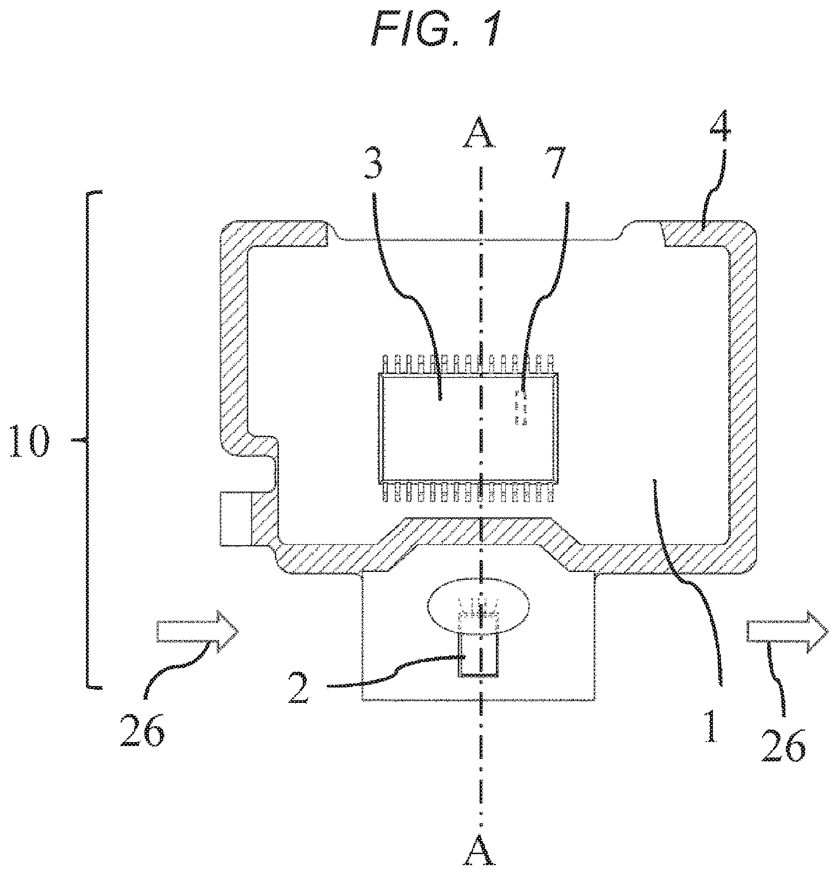
FIG. 1 is a plan view of a sensor assembly according to a first embodiment of the present application.
FIG. 2 is a plan view of a thermal air flow meter according to the first embodiment of the present application.
FIG. 3 is a plan view of the thermal air flow meter that has been sealed by a filling material in the first embodiment of the present application.
FIG. 4 is a cross-sectional view of the thermal air flow meter that has been sealed by the filling material according to the first embodiment of the present application, taken along line C-C.
FIG. 5 is a cross-sectional view of a thermal air flow meter that has been sealed by a filling material according to a second embodiment of the present application when the thermal air flow meter is subjected to a change in temperature.
FIG. 6 is a characteristic diagram of distortion occurring in an electronic component according to the second embodiment of the present application.
FIG. 7 is a plan view of a thermal air flow meter according to a third embodiment of the present application.
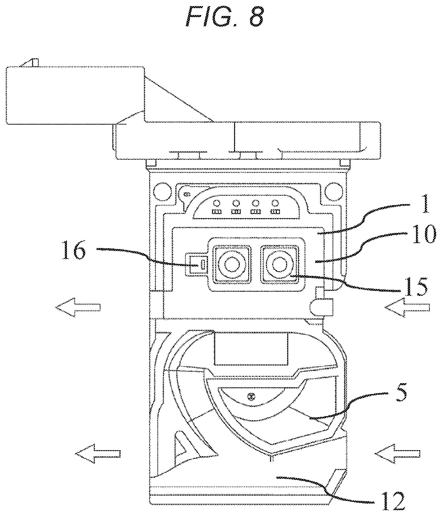
FIG. 8 is a bottom view of the thermal air flow meter according to the third embodiment of the present application.
FIG. 9 is a plan view of the thermal air flow meter that has been sealed by a filling material in the third embodiment of the present application.
FIG. 10 is a plan view of a thermal air flow meter that has been sealed by a filling material in a fourth embodiment of the present application.
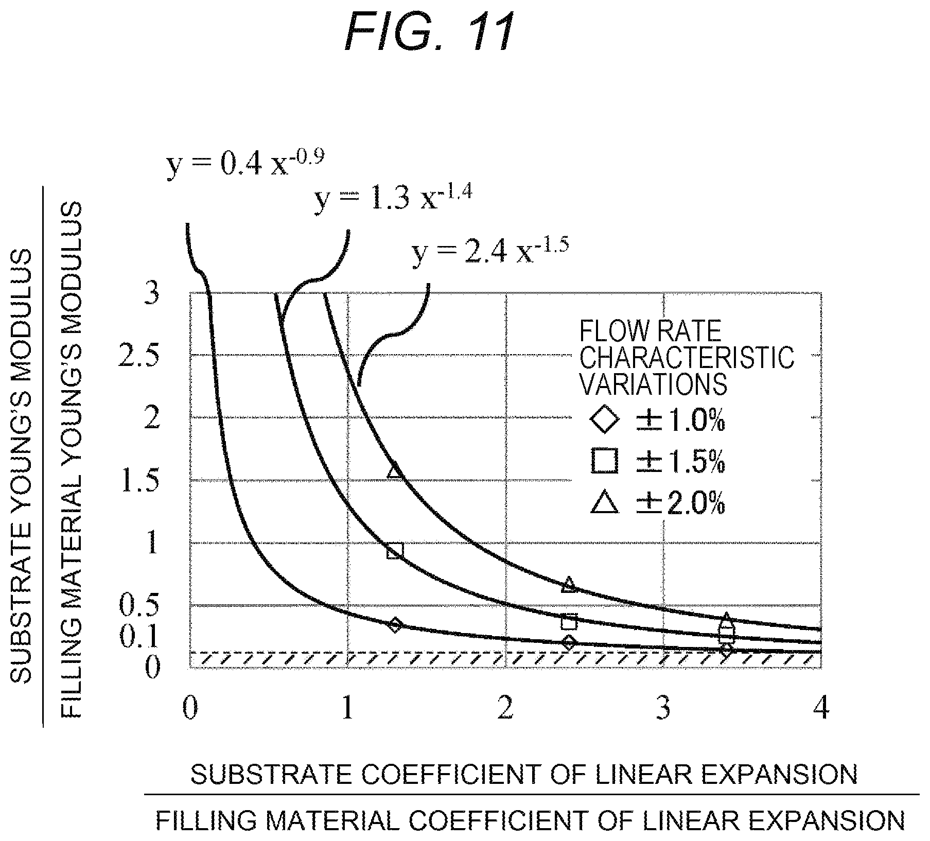
FIG. 11 is a characteristic diagram of distortion occurring in an electronic component according to a fifth embodiment of the present application.
DESCRIPTION OF EMBODIMENTS
Embodiments of the present invention will be described below with reference to the accompanying drawings.
First Embodiment
A thermal air flow meter according to a first embodiment of the present invention will first be described.
As shown in FIG. 1, a sensor assembly 10 includes an electronic component 3 and a sensor chip 2 mounted on a substrate 1. It is noted that a ceramic substrate or a printed substrate may be used for the substrate 1. The electronic component 3 may, for example, be an LSI. A resistor 7 is disposed inside the electronic component 3 and is used, for example, as a reference oscillator (clock) or an A/D converter. The substrate 1 and the sensor chip 2, and the substrate 1 and the electronic component 3, are each electrically wired using a solder or a bonding wire. During flow rate detection, air 26 flows from a direction of the arrow in FIG. 1 or a direction opposite thereto to pass through a flow rate detection part in the sensor chip 2, so that the flow rate is measured.
FIG. 2 is a plan view of the sensor assembly 10 mounted on a housing 5 that includes a sub-passage 12. The housing 5 includes the sub-passage 12 for introducing air that flows through a main passage to the sensor chip 2. The housing 5 formed of a first resin is integrally molded with the sensor assembly 10. The sensor assembly 10 is fixed to the housing 5 via a fixing zone 4 hatched in FIG. 1. The first resin used for the housing 5 is, for example, a thermoplastic resin. In this case, the sensor chip 2 including the flow rate detection part, being intended to measure the air flow rate, is disposed in the sub-passage 12.
FIG. 3 is a plan view of the thermal air flow meter that has been sealed by a filling material 6. FIG. 4 is a cross-sectional view taken along line C-C in FIG. 3. As shown in FIGS. 3 and 4, the filling material 6 is applied to a space formed by the sensor assembly 10 and the housing 5 so as to cover the electronic component 3. An epoxy resin, for example, is used as the filing material.
Effects of the first embodiment will be described below. During flow rate measurement, voltage is applied to the resistor 7 within the electronic component 3, so that the resistor 7 generates heat. The generation of heat increases a temperature of the thermal air flow meter to thereby increase a difference in temperature between the thermal air flow meter and an environment. This results in degraded flow rate measurement accuracy. Thus, the temperature of the thermal air flow meter needs to be prevented from increasing, as caused by the heat generated by the resistor. Covering the electronic component 3 with the filling material 6 as shown in FIG. 3 improves thermal conductivity. This causes the electronic component 3 to readily dissipate heat, so that the temperature can be prevented from increasing. In addition, the thermal air flow meter is applied to flow rate measurement in, for example, a vehicle inwhich an internal combustion engine is mounted, so that the thermal air flow meter is exposed to an environment containing, for example, exhaust gases, gasoline, and salt water. The covering of the electronic component 3 mounted on the sensor assembly 10 with the filling material 6 prevents the electronic component 3 from being exposed to the above environment, so that variations in characteristics of the electronic component 3 can be prevented and a thermal air flow meter offering even higher accuracy can be provided.
Second Embodiment
A second embodiment of the present invention will be described below with reference to FIGS. 5 and 6. FIG. 5 is a cross-sectional view of a thermal air flow meter that, is subjected to a change in temperature. When an electronic component 3 on a sensor assembly 10 is covered with a filling material 6, bending deformation as shown in FIG. 5 occurs in the thermal air flow meter and a substrate 1, as caused by a difference in coefficient, of linear expansion or in resin contraction between the substrate 1 and the filling material 6. This results in stress (distortion) occurring also in a resistor 7 inside the electronic component 3. The stress (distortion) occurring in the resistor 7 causes a resistance value to be varied by a piezo effect, so that an output characteristic of the LSI 3 changes to thus affect measurementaccuracy of the air flow rate. FIG. 6 represents calculations, performed through stress analysis, of variations in a flow rate characteristic caused by thermal stress encountered by the resistor 7 in the electronic component 3 with respect to a ratio of Young's modulus of the filling material 6 to Young's modulus of the substrate 1 and a ratio of a coefficient of linear expansion of the filling material 6 to a coefficient of linear expansion of the substrate 1. In FIG. 6, the ordinate (y-axis) represents the ratio of the Young's modulus of the substrate 1 to the Young's modulus of the filling material 6 and the abscissa (x-axis) represents the ratio of the coefficient of linear expansion of the filling material 6 to the coefficient of linear expansion of the substrate 1. The both ratios are non-dimensional. FIG. 6 plots the relations, as calculated using stress analysis, between the ratio of the Young's modulus of the filling material 6 to the Young's modulus of the substrate 1 and the ratio of the coefficient of linear expansion of the filling material 6 to the coefficient of linear expansion of the substrate 1 when the variations in the flow rate characteristic as caused by the thermal stress encountered by the resistor 7 are .+-.1.0%, .+-.1.5%, and .+-.2.0%. Additionally, using the above plot, the relation between the ratios of the coefficient of linear expansion and the Young's modulus and the variations in the flow rate characteristic is obtained through power approximation. FIG. 6 reveals that the variations in the flow rate characteristic increase with increasing ratios of the coefficient of linear expansion and the Young's modulus.
In the present embodiment, the ratios of the Young's modulus and the coefficient of linear expansion of the substrate 1 to the Young's modulus and the coefficient of linear expansion of the filling material 6 are arranged to fall within a predetermined range indicated by a hatched portion in FIG. 6. Specifically, let x be the ratio of the coefficient of linear expansion of the substrate 1 to the coefficient of linear expansion of the filling material 6 and let y be the ratio of the Young's modulus of the substrate 1 to the Young's modulus of the filling material 6; then, a relation of y<0.4x.sup.-0.9 holds. Through these arrangements, variations in the resistance value of the resistor 7 with changing temperatures can be reduced and the variations in the flow rate characteristic can be held within .+-.1%. Further enhancement of the flow rate detection accuracy can thus be achieved.
Third Embodiment
A third embodiment of the present invention will be described below with reference to FIGS. 7 to 9. FIG. 7 is a plan view of a thermal air flow meter in which a sensor assembly 10 is fixed to a housing 5. FIG. 8 is a bottom view. A configuration of the third embodiment differs from the preceding embodiments in that, as shown in FIGS. 7 and 8, a plurality of electronic components 13 to 16 are disposed on a substrate. Examples of the electronic components include, but are not limited to, a thermistor, a microprocessor, a pressure sensor, and a humidity sensor. As shown in FIG. 7, a bonding wire 20 is used to electrically connect the sensor assembly 10 with a connector 21 disposed in the housing. Examples of the material used for the bonding wire include, but are not limited to, Al, Au, and Cu. FIG. 9 is a plan view of the thermal air flow meter that has been sealed by a filling material 6. Understandably, the configuration shown in FIG. 9 achieves equivalent effects. Furthermore, protection provided for the bonding wire 20 by the filling material 6 can prevent the bonding wire 20 from being deformed from vibration, so that a highly reliable flow meter can be provided.
Fourth Embodiment
A fourth embodiment of the present invention will be described below with reference to FIG. 10.
A configuration of the fourth embodiment differs from the preceding embodiments in that a cover 8 is disposed on a housing 5 for forming a sub-passage and the cover 8 has a hole formed in at least part thereof. This results in a structure in which a filling material 6 is exposed to a main passage for a resultant greater heat dissipating effect of the filling material. Thus, further reduction in a temperature rise due to heat generated by electronic components 3 and 13 to 16 can be achieved. In addition, understandably, a structure featuring tight contact between the cover 8 and the filling material enhances a heat dissipating effect by air flow through the main passage, achieving higher accuracy.
Fifth Embodiment
A fifth embodiment of the present invention will be described below with reference to FIG. 11.
The fifth embodiment differs from the preceding embodiments in that, as shown in FIG. 11, the relation between the ratios of the Young's modulus and the coefficient of linear expansion of the substrate 1 included in the thermal air flow meter to the Young's modulus and the coefficient of linear expansion of the filling material 6 included in the thermal air flow meter falls within a range indicated by the hatched portion in FIG. 11. Specifically, let y be the ratio of the Young's modulus of the substrate 1 to the Young's modulus of the filling material 6; then, a relation of y<0.1 holds. The electronic components 3, and 13 to 16 shown in FIGS. 7 and 8 are electrically connected with a substrate 1 using a solder or a bonding wire. Furthermore, the substrate 1 and a connector 21 disposed in a housing are electrically connected with each other using the bonding wire 20. To enhance reliability of the solder and the bonding wire in terms of thermal deformation and to achieve a long service life, preferably, the difference in coefficient of linear expansion between these bonding materials and the filling material 6 is minimized. Having the relation within the range indicated by the hatched portion in FIG. 11 enables variations in the resistance value to be held within .+-.1% regardless of the ratio of the coefficient of linear expansion of the substrate 1 to the coefficient of linear expansion of the filling material 6. The difference in the coefficient of linear expansion between the solder or bonding wire and the filling material can thus be minimized and variations in the resistance value can be held within .+-.1%, so that a highly reliable flow meter offering high accuracy can be provided.
REFERENCE SIGNS LIST
1 substrate 2 sensor chip 3 electronic component 4 fixing zone 5 housing 6 filling material 7 resistor 8 cover 10 sensor assembly 11 housing 12 sub-passage 13 to 16 electronic component 20 bonding wire 21 connector
* * * * *
References
D00000
D00001
D00002
D00003
D00004
D00005
D00006
D00007
D00008
D00009
D00010
D00011
XML
uspto.report is an independent third-party trademark research tool that is not affiliated, endorsed, or sponsored by the United States Patent and Trademark Office (USPTO) or any other governmental organization. The information provided by uspto.report is based on publicly available data at the time of writing and is intended for informational purposes only.
While we strive to provide accurate and up-to-date information, we do not guarantee the accuracy, completeness, reliability, or suitability of the information displayed on this site. The use of this site is at your own risk. Any reliance you place on such information is therefore strictly at your own risk.
All official trademark data, including owner information, should be verified by visiting the official USPTO website at www.uspto.gov. This site is not intended to replace professional legal advice and should not be used as a substitute for consulting with a legal professional who is knowledgeable about trademark law.