Implant having locking holes with collection cavity for shavings
Rush , et al. February 23, 2
U.S. patent number 10,925,651 [Application Number 16/230,880] was granted by the patent office on 2021-02-23 for implant having locking holes with collection cavity for shavings. This patent grant is currently assigned to DePuy Synthes Products, Inc.. The grantee listed for this patent is DePuy Synthes Products, Inc.. Invention is credited to Simon M. Bosshard, Christopher Keegan, Michael McGurk, Jesse B. Rush.


| United States Patent | 10,925,651 |
| Rush , et al. | February 23, 2021 |
Implant having locking holes with collection cavity for shavings
Abstract
A bone plate includes locking holes that reconfigured to threadedly mate with locking screws to fix the bone plate to an underlying bone. Some of the locking holes are standard-type locking holes. Alternatively or additionally, some of the locking holes are variable-angle locking holes. The bone plate defines a collection cavity in the locking holes that are configured to collect shavings that can be produced if the bone screw is cross threaded in the locking hole.
| Inventors: | Rush; Jesse B. (Telford, PA), Keegan; Christopher (Hatboro, PA), McGurk; Michael (Williamstown, NJ), Bosshard; Simon M. (Bern, CH) | ||||||||||
|---|---|---|---|---|---|---|---|---|---|---|---|
| Applicant: |
|
||||||||||
| Assignee: | DePuy Synthes Products, Inc.
(Raynham, MA) |
||||||||||
| Family ID: | 71098124 | ||||||||||
| Appl. No.: | 16/230,880 | ||||||||||
| Filed: | December 21, 2018 |
Prior Publication Data
| Document Identifier | Publication Date | |
|---|---|---|
| US 20200197056 A1 | Jun 25, 2020 | |
| Current U.S. Class: | 1/1 |
| Current CPC Class: | A61B 17/1728 (20130101); A61B 17/8057 (20130101); A61B 17/8061 (20130101); A61B 17/808 (20130101); A61B 17/8014 (20130101); A61B 17/8605 (20130101); A61B 17/8004 (20130101) |
| Current International Class: | A61B 17/17 (20060101); A61B 17/80 (20060101); A61B 17/86 (20060101) |
References Cited [Referenced By]
U.S. Patent Documents
| 327296 | September 1885 | Mcginnis |
| 1105105 | July 1914 | Sherman |
| 1203546 | October 1916 | Parsons |
| 2228584 | January 1941 | Piace |
| 2352297 | June 1944 | Wales |
| 2414882 | January 1947 | Longfellow |
| 2443363 | June 1948 | Kenneth et al. |
| 2477430 | July 1949 | Swanstrom |
| 2496126 | January 1950 | Haboush |
| 2526959 | October 1950 | Lorenzo |
| 2612159 | September 1952 | Collison |
| 2627855 | February 1953 | Price |
| 2699774 | January 1955 | Livingston |
| 2772676 | December 1956 | Pohl |
| 2801631 | August 1957 | Charnley |
| 2846701 | August 1958 | Bedford, Jr. |
| 2874691 | February 1959 | Mason |
| 3025853 | March 1962 | Mason |
| 3229743 | January 1966 | Derby |
| 3263949 | August 1966 | Conrad |
| 3314326 | April 1967 | Bedford, Jr. |
| 3364807 | January 1968 | Holton |
| 3374786 | March 1968 | Callender, Jr. |
| 3388732 | June 1968 | Holton |
| 3463148 | August 1969 | Treace |
| 3489143 | January 1970 | Halloran |
| 3534731 | October 1970 | Muller |
| 3551389 | December 1970 | Prince, Jr. |
| 3552389 | January 1971 | Allgower et al. |
| 3561437 | February 1971 | Orlich |
| 3577601 | May 1971 | Mariani et al. |
| 3630261 | December 1971 | Gley |
| 3668972 | June 1972 | Allgower et al. |
| 3688972 | September 1972 | Mahon |
| 3695259 | October 1972 | Yost |
| 3695618 | October 1972 | Woolley et al. |
| 3716050 | February 1973 | Johnston |
| 3741205 | June 1973 | Markolf et al. |
| 3744488 | July 1973 | Cox |
| 3779240 | December 1973 | Kondo |
| 3782374 | January 1974 | Fischer |
| 3824995 | July 1974 | Getscher et al. |
| 3842825 | October 1974 | Wagner |
| 3877339 | April 1975 | Muenchinger |
| RE28841 | June 1976 | Martin et al. |
| 3967049 | June 1976 | Brandt |
| 3996834 | December 1976 | Reynolds |
| 3996931 | December 1976 | Callender, Jr. |
| 4009712 | March 1977 | Burstein et al. |
| 4029091 | June 1977 | Von et al. |
| 4040129 | August 1977 | Steinemann et al. |
| 4095591 | June 1978 | Graham et al. |
| 4120298 | October 1978 | Fixel |
| 4172452 | October 1979 | Forte et al. |
| 4175555 | November 1979 | Herbert |
| 4219015 | August 1980 | Steinemann |
| 4236512 | December 1980 | Aginsky |
| 4263904 | April 1981 | Judet |
| 4269180 | May 1981 | Dall et al. |
| 4304039 | December 1981 | Asmus |
| 4338926 | July 1982 | Kummer et al. |
| 4355198 | October 1982 | Gartland, Jr. |
| 4379451 | April 1983 | Getscher |
| 4388921 | June 1983 | Sutter et al. |
| 4408601 | October 1983 | Wenk |
| 4429690 | February 1984 | Angelino-Pievani |
| 4438762 | March 1984 | Kyle |
| 4454876 | June 1984 | Mears |
| RE31628 | July 1984 | Allgower et al. |
| 4484570 | November 1984 | Sutter et al. |
| 4484750 | November 1984 | Scruggs |
| 4488543 | December 1984 | Tornier |
| 4491317 | January 1985 | Bansal |
| 4493317 | January 1985 | Klaue |
| 4494535 | January 1985 | Haig |
| 4513744 | April 1985 | Klaue |
| 4537185 | August 1985 | Stednitz |
| 4565193 | January 1986 | Streli |
| 4580225 | April 1986 | Thompson |
| 4612920 | September 1986 | Lower |
| 4612923 | September 1986 | Kronenthal |
| 4616638 | October 1986 | Griggs |
| 4617922 | October 1986 | Griggs |
| 4621629 | November 1986 | Koeneman |
| 4628923 | December 1986 | Medoff |
| 4629455 | December 1986 | Kanno |
| 4630985 | December 1986 | Simons |
| 4651724 | March 1987 | Berentey et al. |
| 4657001 | April 1987 | Fixel |
| 4683878 | August 1987 | Carter |
| 4717613 | January 1988 | Ottaviano |
| 4747613 | May 1988 | Brichoud et al. |
| 4776329 | October 1988 | Treharne |
| 4776330 | October 1988 | Chapman et al. |
| 4781183 | November 1988 | Casey et al. |
| 4791918 | December 1988 | Von Hasselbach |
| 4794918 | January 1989 | Wolter |
| 4795473 | January 1989 | Grimes |
| 4800874 | January 1989 | David et al. |
| 4838252 | June 1989 | Klaue |
| 4848328 | July 1989 | Laboureau et al. |
| 4858601 | August 1989 | Glisson |
| 4867144 | September 1989 | Karas et al. |
| 4903691 | February 1990 | Heinl |
| 4905680 | March 1990 | Tunc |
| 4927421 | May 1990 | Goble et al. |
| 4955886 | September 1990 | Pawluk |
| 4957496 | September 1990 | Schmidt |
| 4957497 | September 1990 | Hoogland et al. |
| 4964403 | October 1990 | Karas et al. |
| 4966599 | October 1990 | Pollock |
| 4973332 | November 1990 | Kummer |
| 4973333 | November 1990 | Treharne |
| 4988350 | January 1991 | Herzberg |
| 5002544 | March 1991 | Klaue et al. |
| 5006120 | April 1991 | Carter |
| 5013313 | May 1991 | Surer |
| 5013315 | May 1991 | Barrows |
| 5015248 | May 1991 | Burstein et al. |
| 5027904 | July 1991 | Miller et al. |
| 5039265 | August 1991 | Rath et al. |
| 5041113 | August 1991 | Biedermann et al. |
| 5041114 | August 1991 | Chapman et al. |
| 5041116 | August 1991 | Wilson |
| 5053036 | October 1991 | Perren et al. |
| 5085660 | February 1992 | Lin |
| 5087260 | February 1992 | Fixel |
| 5108399 | April 1992 | Eitenmuller et al. |
| 5108449 | April 1992 | Gray |
| 5116336 | May 1992 | Frigg |
| 5127914 | July 1992 | Calderale et al. |
| 5129901 | July 1992 | Decoste |
| 5139497 | August 1992 | Tilghman et al. |
| 5147361 | September 1992 | Ojima et al. |
| 5147363 | September 1992 | Haerle |
| 5151103 | September 1992 | Tepic et al. |
| 5152794 | October 1992 | Davidson |
| 5190544 | March 1993 | Chapman et al. |
| 5197966 | March 1993 | Sommerkamp |
| 5201733 | April 1993 | Etheredge, III |
| 5261910 | November 1993 | Warden et al. |
| 5269784 | December 1993 | Mast |
| 5275601 | January 1994 | Gogolewski et al. |
| 5290281 | March 1994 | Tschakaloff |
| 5300074 | April 1994 | Frigg |
| 5304180 | April 1994 | Slocum |
| 5306275 | April 1994 | Bryan |
| 5324290 | June 1994 | Zdeblick et al. |
| 5324292 | June 1994 | Meyers |
| 5336224 | August 1994 | Selman |
| 5356410 | October 1994 | Pennig |
| 5360429 | November 1994 | Jeanson et al. |
| 5360448 | November 1994 | Thramann |
| 5364398 | November 1994 | Chapman et al. |
| 5364399 | November 1994 | Lowery et al. |
| 5372598 | December 1994 | Luhr et al. |
| 5376126 | December 1994 | Lin |
| 5395372 | March 1995 | Holt et al. |
| 5403136 | April 1995 | Mathys |
| 5413577 | May 1995 | Pollock |
| 5429641 | July 1995 | Gotfried |
| 5433719 | July 1995 | Pennig |
| 5458654 | October 1995 | Tepic |
| 5462547 | October 1995 | Weigum |
| 5484439 | January 1996 | Olson et al. |
| 5514138 | May 1996 | McCarthy |
| 5520690 | May 1996 | Errico et al. |
| 5522902 | June 1996 | Yuan et al. |
| 5531746 | July 1996 | Errico et al. |
| 5534032 | July 1996 | Hodorek |
| 5558674 | September 1996 | Heggeness et al. |
| 5569248 | October 1996 | Mathews |
| 5571109 | November 1996 | Bertagnoli |
| 5571198 | November 1996 | Drucker et al. |
| 5586985 | December 1996 | Putnam et al. |
| 5591168 | January 1997 | Judet et al. |
| 5601551 | February 1997 | Taylor et al. |
| 5601553 | February 1997 | Trebing et al. |
| 5607426 | March 1997 | Ralph et al. |
| 5607427 | March 1997 | Tschakaloff |
| 5607428 | March 1997 | Lin |
| 5620445 | April 1997 | Brosnahan et al. |
| 5647872 | July 1997 | Gilbert et al. |
| 5655089 | August 1997 | Bucci |
| 5658339 | August 1997 | Tronzo et al. |
| 5662655 | September 1997 | Laboureau et al. |
| 5674222 | October 1997 | Berger et al. |
| 5676667 | October 1997 | Hausman |
| 5681311 | October 1997 | Foley et al. |
| D385963 | November 1997 | Hansson |
| 5690633 | November 1997 | Taylor et al. |
| 5693055 | December 1997 | Zahiri et al. |
| 5702396 | December 1997 | Hoenig et al. |
| 5702399 | December 1997 | Kilpela et al. |
| 5709682 | January 1998 | Medoff |
| 5709686 | January 1998 | Talos et al. |
| 5709687 | January 1998 | Pennig |
| 5718704 | February 1998 | Medoff |
| 5718705 | February 1998 | Sammarco |
| 5728099 | March 1998 | Tellman et al. |
| 5733287 | March 1998 | Tepic et al. |
| 5735853 | April 1998 | Olerud |
| 5741256 | April 1998 | Bresina |
| 5741258 | April 1998 | Klaue et al. |
| 5743912 | April 1998 | Lahille et al. |
| 5749872 | May 1998 | Kyle et al. |
| 5766175 | June 1998 | Martinotti |
| 5772662 | June 1998 | Chapman et al. |
| 5779706 | July 1998 | Tschakaloff |
| 5785713 | July 1998 | Jobe |
| 5797916 | August 1998 | McDowell |
| 5800553 | September 1998 | Albrektsson et al. |
| 5810821 | September 1998 | Vandewalle |
| 5810822 | September 1998 | Mortier |
| 5810823 | September 1998 | Klaue et al. |
| 5827286 | October 1998 | Incavo et al. |
| 5853413 | December 1998 | Carter et al. |
| 5921988 | July 1999 | Legrand |
| 5928084 | July 1999 | Green |
| 5931801 | August 1999 | Burbank et al. |
| 5931839 | August 1999 | Medoff |
| 5938664 | August 1999 | Winquist et al. |
| 5954722 | September 1999 | Bono |
| 5961524 | October 1999 | Crombie |
| 5968046 | October 1999 | Castleman |
| 5968047 | October 1999 | Reed |
| 5973223 | October 1999 | Tellman et al. |
| 5976139 | November 1999 | Bramlet |
| 5976141 | November 1999 | Haag et al. |
| 5989255 | November 1999 | Pepper et al. |
| 5999940 | December 1999 | Ranger |
| 6001099 | December 1999 | Huebner |
| 6007535 | December 1999 | Rayhack et al. |
| 6022352 | February 2000 | Vandewalle |
| 6030162 | February 2000 | Huebner |
| 6030389 | February 2000 | Wagner et al. |
| 6059785 | May 2000 | Schavan et al. |
| 6066141 | May 2000 | Dall et al. |
| 6096040 | August 2000 | Esser |
| 6113603 | September 2000 | Medoff |
| 6129728 | October 2000 | Schumacher et al. |
| 6129730 | October 2000 | Bono et al. |
| 6152927 | November 2000 | Farris et al. |
| 6155756 | December 2000 | Mericle et al. |
| 6183474 | February 2001 | Bramlet et al. |
| 6183475 | February 2001 | Lester et al. |
| 6187007 | February 2001 | Frigg et al. |
| 6206881 | March 2001 | Frigg et al. |
| 6221073 | April 2001 | Weiss et al. |
| 6221075 | April 2001 | Toermala et al. |
| D443060 | May 2001 | Benirschke et al. |
| 6224602 | May 2001 | Hayes |
| 6228085 | May 2001 | Theken et al. |
| 6235032 | May 2001 | Link |
| 6235033 | May 2001 | Brace et al. |
| 6258250 | July 2001 | Weissenbacher et al. |
| 6261291 | July 2001 | Talaber et al. |
| 6283969 | September 2001 | Grusin et al. |
| 6287309 | September 2001 | Baccelli et al. |
| 6290703 | September 2001 | Ganem |
| 6306136 | October 2001 | Baccelli |
| 6306140 | October 2001 | Siddiqui |
| 6322562 | November 2001 | Wolter |
| 6325803 | December 2001 | Schumacher et al. |
| 6338734 | January 2002 | Burke et al. |
| 6342055 | January 2002 | Eisermann et al. |
| 6348052 | February 2002 | Sammarco |
| 6350265 | February 2002 | Blaustein et al. |
| 6355041 | March 2002 | Martin |
| 6355042 | March 2002 | Winquist et al. |
| 6358250 | March 2002 | Orbay |
| 6364882 | April 2002 | Orbay |
| 6375657 | April 2002 | Doubler et al. |
| 6379359 | April 2002 | Dahners |
| D458374 | June 2002 | Bryant et al. |
| D458683 | June 2002 | Bryant et al. |
| D458684 | June 2002 | Bryant et al. |
| D458996 | June 2002 | Bryant et al. |
| 6423064 | July 2002 | Kluger |
| 6440131 | August 2002 | Haidukewych |
| 6440135 | August 2002 | Orbay et al. |
| D463557 | September 2002 | Bryant et al. |
| D463558 | September 2002 | Bryant et al. |
| D463559 | September 2002 | Bryant et al. |
| 6454769 | September 2002 | Wagner et al. |
| 6454770 | September 2002 | Klaue |
| D464136 | October 2002 | Bryant et al. |
| D464731 | October 2002 | Bryant et al. |
| 6468278 | October 2002 | Mueckter |
| 6488685 | December 2002 | Manderson |
| D469532 | January 2003 | Bryant et al. |
| D469533 | January 2003 | Bryant et al. |
| D469534 | January 2003 | Bryant et al. |
| 6503252 | January 2003 | Hansson |
| 6503281 | January 2003 | Mallory |
| 6508819 | January 2003 | Orbay |
| D469874 | February 2003 | Bryant et al. |
| D469875 | February 2003 | Bryant et al. |
| D470588 | February 2003 | Bryant et al. |
| 6525525 | February 2003 | Azinger |
| 6527776 | March 2003 | Michelson |
| 6533789 | March 2003 | Hall et al. |
| 6565525 | May 2003 | Burbank et al. |
| 6565569 | May 2003 | Assaker et al. |
| 6575975 | June 2003 | Brace et al. |
| 6602256 | August 2003 | Hayes |
| 6605090 | August 2003 | Trieu et al. |
| D479331 | September 2003 | Pike et al. |
| D480141 | September 2003 | Benirschke et al. |
| 6623486 | September 2003 | Weaver et al. |
| 6648891 | November 2003 | Kim |
| 6666868 | December 2003 | Fallin |
| 6669700 | December 2003 | Farris et al. |
| 6669701 | December 2003 | Steiner et al. |
| 6712820 | March 2004 | Orbay |
| 6719759 | April 2004 | Wagner et al. |
| 6730091 | May 2004 | Pfefferle et al. |
| 6767351 | July 2004 | Orbay et al. |
| 6835197 | December 2004 | Roth et al. |
| 6863483 | March 2005 | Koenig et al. |
| 6866665 | March 2005 | Orbay |
| 6875215 | April 2005 | Taras et al. |
| 6893443 | May 2005 | Frigg et al. |
| 6955677 | October 2005 | Dahners |
| 6974461 | December 2005 | Wolter |
| 7001388 | February 2006 | Orbay et al. |
| 7044953 | May 2006 | Capanni |
| 7128744 | October 2006 | Weaver et al. |
| 7169149 | January 2007 | Hajianpour |
| 7179260 | February 2007 | Gerlach et al. |
| 7229445 | June 2007 | Hayeck et al. |
| 7282053 | October 2007 | Orbay |
| 7294130 | November 2007 | Orbay |
| 7309340 | December 2007 | Fallin et al. |
| 7316687 | January 2008 | Aikins et al. |
| 7338491 | March 2008 | Baker et al. |
| 7341589 | March 2008 | Weaver et al. |
| 7354441 | April 2008 | Frigg |
| 7517350 | April 2009 | Weiner et al. |
| 7527639 | May 2009 | Orbay et al. |
| 7537596 | May 2009 | Jensen |
| 7635381 | December 2009 | Orbay |
| 7637928 | December 2009 | Fernandez |
| 7641677 | January 2010 | Weiner et al. |
| 7695472 | April 2010 | Young |
| 7695502 | April 2010 | Orbay et al. |
| 7766916 | August 2010 | Leyden et al. |
| 7771433 | August 2010 | Orbay et al. |
| 7771457 | August 2010 | Kay et al. |
| 7776076 | August 2010 | Grady et al. |
| 7776916 | August 2010 | Freeman et al. |
| 7857838 | December 2010 | Orbay |
| 7867260 | January 2011 | Meyer et al. |
| 7905909 | March 2011 | Orbay et al. |
| 7951176 | May 2011 | Grady et al. |
| 8075561 | December 2011 | Wolter |
| 8092505 | January 2012 | Sommers |
| 8118846 | February 2012 | Leither et al. |
| 8118848 | February 2012 | Ducharme et al. |
| 8337535 | December 2012 | White et al. |
| 8343196 | January 2013 | Schneider |
| 8403967 | March 2013 | Orbay |
| 8506607 | August 2013 | Eckhof et al. |
| 8518042 | August 2013 | Winslow et al. |
| 8556945 | October 2013 | Orbay |
| 8574268 | November 2013 | Chan et al. |
| 8579946 | November 2013 | Orbay |
| 8641744 | February 2014 | Weaver et al. |
| 8758346 | June 2014 | Koay et al. |
| 8814918 | August 2014 | Orbay et al. |
| 8845698 | September 2014 | Schneider |
| 8852245 | October 2014 | Schneider |
| 8876873 | November 2014 | Schneider |
| 8894693 | November 2014 | Petit et al. |
| 8940029 | January 2015 | Leung et al. |
| 9072558 | July 2015 | Orbay |
| 9107711 | August 2015 | Hainard |
| 9168075 | October 2015 | Dell Oca |
| 9265542 | February 2016 | Koay et al. |
| 9277947 | March 2016 | Koay et al. |
| 9295505 | March 2016 | Schneider |
| 9308034 | April 2016 | Grady |
| 9314284 | April 2016 | Chan et al. |
| 9387022 | July 2016 | Koay |
| 9433454 | September 2016 | Paolino et al. |
| 9498267 | November 2016 | Pfeiffer et al. |
| 9510880 | December 2016 | Terrill et al. |
| 9554909 | January 2017 | Donner et al. |
| 9855083 | January 2018 | Mighell et al. |
| 9867643 | January 2018 | Terrill et al. |
| 9931148 | April 2018 | Grady |
| 2001/0000186 | April 2001 | Bramlet et al. |
| 2001/0011172 | August 2001 | Orbay et al. |
| 2001/0012940 | August 2001 | Tunc |
| 2002/0013587 | January 2002 | Winquist et al. |
| 2002/0032446 | March 2002 | Orbay |
| 2002/0045901 | April 2002 | Wagner et al. |
| 2002/0049445 | April 2002 | Hall et al. |
| 2002/0062127 | May 2002 | Schumacher et al. |
| 2002/0065516 | May 2002 | Winquist et al. |
| 2002/0128654 | September 2002 | Steger et al. |
| 2002/0143337 | October 2002 | Orbay et al. |
| 2002/0143338 | October 2002 | Orbay et al. |
| 2002/0156474 | October 2002 | Inack et al. |
| 2002/0183752 | December 2002 | Steiner et al. |
| 2002/0183753 | December 2002 | Manderson |
| 2003/0040748 | February 2003 | Aikins et al. |
| 2003/0055435 | March 2003 | Barrick |
| 2003/0060827 | March 2003 | Coughlin |
| 2003/0083660 | May 2003 | Orbay |
| 2003/0083661 | May 2003 | Orbay et al. |
| 2003/0105461 | June 2003 | Putnam |
| 2003/0125738 | July 2003 | Khanna |
| 2003/0135212 | July 2003 | Y Chow |
| 2003/0135216 | July 2003 | Sevrain |
| 2004/0030339 | February 2004 | Wack et al. |
| 2004/0049193 | March 2004 | Capanni |
| 2004/0059334 | March 2004 | Weaver et al. |
| 2004/0059335 | March 2004 | Weaver et al. |
| 2004/0073218 | April 2004 | Dahners |
| 2004/0097937 | May 2004 | Pike et al. |
| 2004/0097941 | May 2004 | Weiner et al. |
| 2004/0111089 | June 2004 | Stevens et al. |
| 2004/0215198 | October 2004 | Marnay et al. |
| 2004/0254579 | December 2004 | Buhren et al. |
| 2004/0260291 | December 2004 | Jensen |
| 2004/0260306 | December 2004 | Fallin et al. |
| 2005/0015089 | January 2005 | Young et al. |
| 2005/0049593 | March 2005 | Duong et al. |
| 2005/0080421 | April 2005 | Weaver et al. |
| 2005/0085818 | April 2005 | Huebner |
| 2005/0107796 | May 2005 | Gerlach et al. |
| 2005/0165400 | July 2005 | Fernandez |
| 2005/0171544 | August 2005 | Falkner, Jr. |
| 2005/0187555 | August 2005 | Biedermann et al. |
| 2005/0216001 | September 2005 | David |
| 2005/0261688 | November 2005 | Grady et al. |
| 2005/0277937 | December 2005 | Leung et al. |
| 2006/0004361 | January 2006 | Hayeck et al. |
| 2006/0009771 | January 2006 | Orbay et al. |
| 2006/0058797 | March 2006 | Mathieu et al. |
| 2006/0200151 | September 2006 | Ducharme et al. |
| 2006/0217722 | September 2006 | Dutoit et al. |
| 2006/0235400 | October 2006 | Schneider |
| 2006/0264946 | November 2006 | Young |
| 2007/0016205 | January 2007 | Beutter et al. |
| 2007/0083207 | April 2007 | Ziolo et al. |
| 2007/0088360 | April 2007 | Orbay |
| 2007/0162016 | July 2007 | Matityahu |
| 2007/0206244 | September 2007 | Kobayashi |
| 2007/0208378 | September 2007 | Bonutti et al. |
| 2007/0225716 | September 2007 | Deffenbaugh et al. |
| 2007/0260244 | November 2007 | Wolter |
| 2007/0276386 | November 2007 | Gerlach et al. |
| 2007/0276402 | November 2007 | Frankel et al. |
| 2008/0065070 | March 2008 | Freid et al. |
| 2008/0132960 | June 2008 | Weaver et al. |
| 2008/0140130 | June 2008 | Chan et al. |
| 2008/0208259 | August 2008 | Gilbert et al. |
| 2008/0234749 | September 2008 | Forstein |
| 2008/0234752 | September 2008 | Dahners |
| 2008/0300637 | December 2008 | Austin et al. |
| 2009/0018557 | January 2009 | Pisharodi |
| 2009/0018588 | January 2009 | Eckhof et al. |
| 2009/0036933 | February 2009 | Dube et al. |
| 2009/0076553 | March 2009 | Wolter |
| 2009/0076554 | March 2009 | Huebner et al. |
| 2009/0099610 | April 2009 | Johnson et al. |
| 2009/0118768 | May 2009 | Sixto et al. |
| 2009/0143824 | June 2009 | Austin et al. |
| 2009/0143825 | June 2009 | Graham et al. |
| 2009/0216242 | August 2009 | Riemer et al. |
| 2009/0281543 | November 2009 | Orbay et al. |
| 2009/0287258 | November 2009 | Vannemreddy |
| 2009/0292318 | November 2009 | White et al. |
| 2009/0312803 | December 2009 | Austin |
| 2010/0016858 | January 2010 | Michel |
| 2010/0030277 | February 2010 | Haidukewych et al. |
| 2010/0057086 | March 2010 | Price et al. |
| 2010/0076496 | March 2010 | Fernandez |
| 2010/0094357 | April 2010 | Wallenstein et al. |
| 2010/0100134 | April 2010 | Mocanu |
| 2010/0137919 | June 2010 | Wolter |
| 2010/0274296 | October 2010 | Appenzeller et al. |
| 2010/0312285 | December 2010 | White et al. |
| 2010/0312286 | December 2010 | Dell Oca |
| 2011/0046681 | February 2011 | Prandi et al. |
| 2011/0087229 | April 2011 | Kubiak et al. |
| 2011/0106081 | May 2011 | Graham et al. |
| 2011/0224671 | September 2011 | Koay et al. |
| 2011/0301608 | December 2011 | Roth et al. |
| 2012/0143193 | June 2012 | Hulliger |
| 2012/0197307 | August 2012 | Fritzinger et al. |
| 2012/0245642 | September 2012 | Giannoudis et al. |
| 2013/0096631 | April 2013 | Leung |
| 2013/0116735 | May 2013 | Schneider |
| 2013/0172943 | July 2013 | Austin et al. |
| 2013/0190828 | July 2013 | Schneider |
| 2013/0197589 | August 2013 | Schneider |
| 2013/0245699 | September 2013 | Orbay et al. |
| 2013/0261675 | October 2013 | Fritzinger |
| 2014/0005728 | January 2014 | Koay |
| 2014/0018862 | January 2014 | Koay et al. |
| 2014/0180345 | June 2014 | Chan et al. |
| 2014/0207194 | July 2014 | Wolter |
| 2014/0236154 | August 2014 | Liao et al. |
| 2014/0271028 | September 2014 | Arnett |
| 2014/0277180 | September 2014 | Paolino et al. |
| 2014/0316473 | October 2014 | Pfeiffer et al. |
| 2014/0324108 | October 2014 | Orbay et al. |
| 2015/0051651 | February 2015 | Terrill et al. |
| 2015/0105829 | April 2015 | Laird |
| 2015/0257802 | September 2015 | Wolf et al. |
| 2015/0327897 | November 2015 | Hulliger |
| 2015/0327898 | November 2015 | Martin |
| 2015/0359575 | December 2015 | Pech et al. |
| 2016/0074081 | March 2016 | Weaver et al. |
| 2016/0089191 | March 2016 | Pak et al. |
| 2016/0143676 | May 2016 | Koay et al. |
| 2016/0166294 | June 2016 | Schneider |
| 2016/0242829 | August 2016 | Kim et al. |
| 2016/0278826 | September 2016 | Epperly |
| 2016/0310184 | October 2016 | Kazanovicz et al. |
| 2016/0317205 | November 2016 | Baker |
| 2016/0367299 | December 2016 | Paolino et al. |
| 2017/0265915 | September 2017 | Langdale |
| 2017/0319248 | November 2017 | Milella et al. |
| 2018/0008326 | January 2018 | Hulliger et al. |
| 2018/0036049 | February 2018 | Kobayashi |
| 2018/0064476 | March 2018 | Lopez et al. |
| 2018/0064477 | March 2018 | Lopez |
| 2018/0064479 | March 2018 | Lopez et al. |
| 2018/0132913 | May 2018 | Davison |
| 2018/0235681 | August 2018 | Chambers |
| 2019/0290338 | September 2019 | Bosshard |
| 2019/0298426 | October 2019 | Bosshard et al. |
| 1112803 | Nov 1981 | CA | |||
| 2047521 | Jan 1992 | CA | |||
| 2536960 | Mar 2005 | CA | |||
| 611147 | May 1979 | CH | |||
| 670755 | Jul 1989 | CH | |||
| 672245 | Nov 1989 | CH | |||
| 675531 | Oct 1990 | CH | |||
| 1486162 | Mar 2004 | CN | |||
| 2933637 | Apr 1980 | DE | |||
| 3442004 | Apr 1986 | DE | |||
| 3722852 | Jan 1989 | DE | |||
| 3743638 | Jul 1989 | DE | |||
| 4004941 | Aug 1990 | DE | |||
| 3942326 | Jun 1991 | DE | |||
| 4201531 | Jul 1993 | DE | |||
| 4341980 | Jun 1995 | DE | |||
| 4343117 | Jun 1995 | DE | |||
| 4438264 | Mar 1996 | DE | |||
| 19636733 | Apr 1997 | DE | |||
| 19629011 | Jan 1998 | DE | |||
| 9321544 | Sep 1999 | DE | |||
| 19832513 | Feb 2000 | DE | |||
| 19858889 | Jun 2000 | DE | |||
| 10015734 | Sep 2001 | DE | |||
| 10125092 | Dec 2001 | DE | |||
| 20309361 | Sep 2003 | DE | |||
| 20317651 | Mar 2004 | DE | |||
| 10319781 | Aug 2004 | DE | |||
| 102004009429 | Sep 2005 | DE | |||
| 102005042766 | Jan 2007 | DE | |||
| 202006019220 | May 2007 | DE | |||
| 202008000914 | Mar 2008 | DE | |||
| 202007017159 | May 2008 | DE | |||
| 102010048052 | Apr 2012 | DE | |||
| 102016112845 | Jan 2018 | DE | |||
| 202014011161 | Mar 2018 | DE | |||
| 0053999 | Jun 1982 | EP | |||
| 0158030 | Oct 1985 | EP | |||
| 0180532 | May 1986 | EP | |||
| 0207884 | Jan 1987 | EP | |||
| 0241914 | Oct 1987 | EP | |||
| 0244782 | Nov 1987 | EP | |||
| 0251583 | Jan 1988 | EP | |||
| 0266146 | May 1988 | EP | |||
| 0274713 | Jul 1988 | EP | |||
| 0290138 | Nov 1988 | EP | |||
| 0291632 | Nov 1988 | EP | |||
| 0299160 | Jan 1989 | EP | |||
| 0337288 | Oct 1989 | EP | |||
| 0360139 | Mar 1990 | EP | |||
| 0381462 | Aug 1990 | EP | |||
| 0382256 | Aug 1990 | EP | |||
| 0410309 | Jan 1991 | EP | |||
| 0436885 | Jul 1991 | EP | |||
| 0471418 | Feb 1992 | EP | |||
| 0506420 | Sep 1992 | EP | |||
| 0515828 | Dec 1992 | EP | |||
| 0530585 | Mar 1993 | EP | |||
| 0532421 | Mar 1993 | EP | |||
| 0546460 | Jun 1993 | EP | |||
| 0649635 | Apr 1995 | EP | |||
| 0668059 | Aug 1995 | EP | |||
| 0760231 | Mar 1997 | EP | |||
| 0848600 | Jun 1998 | EP | |||
| 1132052 | Sep 2001 | EP | |||
| 1468655 | Oct 2004 | EP | |||
| 1568329 | Aug 2005 | EP | |||
| 1604619 | Dec 2005 | EP | |||
| 1658015 | May 2006 | EP | |||
| 1712197 | Oct 2006 | EP | |||
| 1741397 | Jan 2007 | EP | |||
| 1767160 | Mar 2007 | EP | |||
| 1878394 | Jan 2008 | EP | |||
| 2529685 | Dec 2012 | EP | |||
| 0742618 | Mar 1933 | FR | |||
| 2233973 | Jan 1975 | FR | |||
| 2405062 | May 1979 | FR | |||
| 2405705 | May 1979 | FR | |||
| 2405706 | May 1979 | FR | |||
| 2496429 | Jun 1982 | FR | |||
| 2606268 | May 1988 | FR | |||
| 2622431 | May 1989 | FR | |||
| 2650500 | Feb 1991 | FR | |||
| 2671966 | Jul 1992 | FR | |||
| 2674118 | Sep 1992 | FR | |||
| 2677876 | Dec 1992 | FR | |||
| 2706763 | Dec 1994 | FR | |||
| 2739151 | Mar 1997 | FR | |||
| 2757370 | Jun 1998 | FR | |||
| 2802082 | Jun 2001 | FR | |||
| 0997733 | Jul 1965 | GB | |||
| 1237405 | Jun 1971 | GB | |||
| 1250413 | Oct 1971 | GB | |||
| 1312189 | Apr 1973 | GB | |||
| 1385398 | Feb 1975 | GB | |||
| 2017502 | Oct 1979 | GB | |||
| 1575194 | Sep 1980 | GB | |||
| 2090745 | Jul 1982 | GB | |||
| 2245498 | Jan 1992 | GB | |||
| 2257913 | Jan 1993 | GB | |||
| 02-121652 | May 1990 | JP | |||
| 03-058150 | Mar 1991 | JP | |||
| 03-158150 | Jul 1991 | JP | |||
| 04-138152 | May 1992 | JP | |||
| 06-045941 | Feb 1994 | JP | |||
| 06-125918 | May 1994 | JP | |||
| 06-245941 | Sep 1994 | JP | |||
| 08-098846 | Apr 1996 | JP | |||
| 08-126650 | May 1996 | JP | |||
| 08-257034 | Oct 1996 | JP | |||
| 08-266562 | Oct 1996 | JP | |||
| 09-108237 | Apr 1997 | JP | |||
| 10-118096 | May 1998 | JP | |||
| 11-076259 | Mar 1999 | JP | |||
| 11-299804 | Aug 1999 | JP | |||
| 11-276501 | Oct 1999 | JP | |||
| 11-512004 | Oct 1999 | JP | |||
| 11-318930 | Nov 1999 | JP | |||
| 2000-000247 | Jan 2000 | JP | |||
| 2000-152944 | Jun 2000 | JP | |||
| 2001-149379 | Jun 2001 | JP | |||
| 2001-161704 | Jun 2001 | JP | |||
| 2001-514039 | Sep 2001 | JP | |||
| 2001-525701 | Dec 2001 | JP | |||
| 2001-525702 | Dec 2001 | JP | |||
| 2002-095673 | Apr 2002 | JP | |||
| 2002-232185 | Aug 2002 | JP | |||
| 2002-532185 | Oct 2002 | JP | |||
| 2002-345836 | Dec 2002 | JP | |||
| 2002-542875 | Dec 2002 | JP | |||
| 2003-024344 | Jan 2003 | JP | |||
| 2003-038508 | Feb 2003 | JP | |||
| 2003-038509 | Feb 2003 | JP | |||
| 2003-509107 | Mar 2003 | JP | |||
| 2003-521303 | Jul 2003 | JP | |||
| 10-2007-0034449 | Mar 2007 | KR | |||
| 10-2008-0028917 | Apr 2008 | KR | |||
| 1037911 | Aug 1983 | SU | |||
| 1279626 | Dec 1986 | SU | |||
| 87/00419 | Jan 1987 | WO | |||
| 87/06982 | Nov 1987 | WO | |||
| 88/03781 | Jun 1988 | WO | |||
| 92/11819 | Jul 1992 | WO | |||
| 93/11714 | Jun 1993 | WO | |||
| 93/15678 | Aug 1993 | WO | |||
| 93/22982 | Nov 1993 | WO | |||
| 94/02073 | Feb 1994 | WO | |||
| 95/32674 | Dec 1995 | WO | |||
| 96/17556 | Jun 1996 | WO | |||
| 96/25892 | Aug 1996 | WO | |||
| 96/29948 | Oct 1996 | WO | |||
| 97/08999 | Mar 1997 | WO | |||
| 97/09000 | Mar 1997 | WO | |||
| 97/20514 | Jun 1997 | WO | |||
| 98/02105 | Jan 1998 | WO | |||
| 98/05263 | Feb 1998 | WO | |||
| 98/51226 | Nov 1998 | WO | |||
| 98/51368 | Nov 1998 | WO | |||
| 99/25266 | May 1999 | WO | |||
| 99/44529 | Sep 1999 | WO | |||
| 00/53110 | Sep 2000 | WO | |||
| 00/53111 | Sep 2000 | WO | |||
| 00/66012 | Nov 2000 | WO | |||
| 01/19267 | Mar 2001 | WO | |||
| 01/19268 | Mar 2001 | WO | |||
| 01/26566 | Apr 2001 | WO | |||
| 01/54601 | Aug 2001 | WO | |||
| 01/89400 | Nov 2001 | WO | |||
| 02/71963 | Sep 2002 | WO | |||
| 02/96309 | Dec 2002 | WO | |||
| 03/02856 | Jan 2003 | WO | |||
| 03/22166 | Mar 2003 | WO | |||
| 03/28567 | Apr 2003 | WO | |||
| 03/57055 | Jul 2003 | WO | |||
| 2004/043277 | May 2004 | WO | |||
| 2004/089233 | Oct 2004 | WO | |||
| 2004/107957 | Dec 2004 | WO | |||
| 2005/018472 | Mar 2005 | WO | |||
| 2005/044121 | May 2005 | WO | |||
| 2007/014279 | Feb 2007 | WO | |||
| 2007/108734 | Sep 2007 | WO | |||
| 2009/023666 | Feb 2009 | WO | |||
| 2009/058969 | May 2009 | WO | |||
| 2011/032140 | Mar 2011 | WO | |||
| 2012/112327 | Aug 2012 | WO | |||
| 2013/045713 | Apr 2013 | WO | |||
| 2017/048909 | Mar 2017 | WO | |||
Other References
|
Zimmer Advertisement, J. of Orthopaedic Trauma, vol. 12, No. 5, Jun./Jul. 1998. cited by applicant . Vattolo, M., Thesis, "The Effect of Grooves in Osteosynthesis Plates on the Restructuring of the Corticalis," Laboratory for Experimental Surgery, Swiss Research Institute, 1986 (original in German, translation to English attached with Certification). cited by applicant . U.S. Appl. No. 15/940,761, Locking Structures for Affixing Bone Anchors to a Bone Plate, and Related Systems and Methods, filed Mar. 29, 2018. cited by applicant . U.S. Appl. No. 15/926,390, Bone Plate With Form-Fitting Variable-Angle Locking Hole, filed Mar. 20, 2018. cited by applicant . Update, Titanium LC-DCP Condylar Buttress Plate, Jun. 15,1995 (Synthes) ("The LC-DCP update"). cited by applicant . Universelle Rekonstruktionsplatte URP 2 4-3.2 (UniRecon-Registered), Swiss Dent, 17,1996, pp. 19-25. cited by applicant . The Titanium Distal Radius Plate Technique Guide, published by Synthes, 1997. cited by applicant . The Titanium Distal Radius Plate Technique Guide, (the "DRP Guide") published by Synthes in 1996. cited by applicant . The Locking Reconstruction Plate Technique Guide, published by Synthes, 1997. cited by applicant . The Distal Radius Plate Instrument and Implant Set Technique Guide, (Synthes) ("1999 Radius Plate Guide"). cited by applicant . The Distal Radius Plate Instrument and Implant Set Technique Guide, (Synthes) ("1998 Radius Plate Guide"). cited by applicant . Technique Guide: 2.4 mm Variable Angle LCP Distal Radius System. Synthes, 2008,43 pages. cited by applicant . Technique Guide, Less Invasive Stabilization (LISS), Oct. 2003. cited by applicant . Synthes' Supporting Memorandum for Reconsideration of Claim Construction (without supporting Declaration) in the Pennsylvania Action, dated Feb. 19, 2008. cited by applicant . Synthes' Summary Judgment Motion of No Invalidity Based on K982222 Summary including supporting memorandum, and declarations of A. Silversti and B. Liu (with supporting exhibits), dated Sep. 10, 2008. cited by applicant . Synthes' Responsive Claim Construction Brief (without exhibits) for the Pennsylvania Action, dated Apr. 20, 2007. cited by applicant . Synthes' Response to Smith & Nephew's Statement of Facts in Support of Smith & Nephew's Motion for Summary Judgment of Invalidity of the '744 patent; dated Sep. 29, 2008; 19 pages. cited by applicant . Synthes' Response to Motion for Leave to Amend Answer, Civil Action No. Mar. 0084 (E.D. Pa.), dated Aug. 9, 2007. cited by applicant . Synthes' Reply to Smith & Nephew's Opposition to Synthes Motion for Reconsideration of Claim Construction for the '486 patent in the Pennsylvania Action, dated Mar. 14, 2008. cited by applicant . Synthes' Opposition to Smith & Nephew's Motion for Summary Judgment of Invalidity of the '744 patent; dated Sep. 29, 2008; 22 pages. cited by applicant . Synthes' Opening Claim Construction Brief (without supporting declaration and attached exhibits but including Appendix A & B) for the Pennsylvania Action, dated Mar. 16, 2007 (Dkt. 54) (Ex. 5). cited by applicant . Synthes' 1996 Titanium Modular Hand System brochure (the "Hand System Brochure") [SNI-0290287-294] (Ex. 47). cited by applicant . Synthes Titanium Modular Hand System, 1996. cited by applicant . Synthes Opposition to Smith & Nephew's Motion for Summary Judgment of Invalidity of Claims 10-12 of the '486 Patent, dated Sep. 29, 2008 (Dkt. 159) (Ex 67). cited by applicant . Synthes 1997 Catalog, published by Synthes, Mar. 1997; part 2, 261 pgs. cited by applicant . Synthes 1997 Catalog, published by Synthes, Mar. 1997; part 1, 200 pgs. cited by applicant . Sutter, F., et al., "Titanplasma-beschichtetes Hohlschrauben--und Rekonstructions-platten-System (THRP) zur Oberbriickung van Kieferdefekten," Chirurg No. 55, pp. 741-748,1984 [SNI-0006164-171], and translation thereof [SNI-0006152-163] (Ex. 33). cited by applicant . Surgical Instruments Catalog, Collin & Co., 1935 (original in French, translation to English of pp. 392-397 attached with certification). cited by applicant . Supplemental Expert Report of Clifford FI. Turen, M.D., May 2009 (with Exhibit 1), dated Aug. 8, 2008(Ex.60). cited by applicant . Supplement to Apr. 9, 2008 Expert Report of John F. Witherspoon (without exhibits), dated May 14, 2008 (Ex. 74). cited by applicant . Supplement to Apr. 9, 2008 Expert Report of J. Lawrence Marsh in the Pennsylvania Action (with Exhibit 1), dated May 14, 2008 (Ex. 46). cited by applicant . Summary of Safety and Effectiveness Information [510(k) Summary], K982222, Jul. 29, 1998. cited by applicant . Stryker, "VariAx Distal Radius: Locking Plate System", wwvv.osteosynthesis.stryker.com, 2006, 12 pages. cited by applicant . Stay Order in Pennsylvania Action, dated Jul. 13, 2009. cited by applicant . Smith and Nephew's Opposition to Synthes Motion for Summary Judgment of No Invalidity Based on K982222(including Opposition Memorandum, Statement of Undisputed Facts, K. Doyle Declaration with Exhibits A-F and R. King's Declaration with Exhibits A-D), dated Sep. 29, 2008( Dkt. 154) (Ex. 63). cited by applicant . Smith & Newphew Statement of Undisputed Facts in Support of its Motion for Summary Judgment of Invalidity of U.S. Pat. No. 7,128,744; dated Sep. 29, 2008; 8 pages. cited by applicant . Smith & Nephew, Inc. v. Rea, Federal Circuit Opinion dated Jul. 9, 2013, 18 pages. cited by applicant . Smith & Nephew's Third Supplemental Response to Interrogatories Nos. 4, 5, 6, 8 and 9; Second Supplemental Responses to Interrogatories Nos. 1,2, 3,10,11 and 12; and First Supplemental Responses to Interrogatories Nos. 13,15 and 17 (with Smith & Nephew Exhibit 1 thereto), dated Aug. 11, 2008 (Ex. 14). cited by applicant . Smith & Nephew's Responsive Claim Construction Brief (without exhibits) for the Pennsylvania Action, dated Apr. 20, 2007 (Dkt. 60) (Ex. 8). cited by applicant . Smith & Nephew's Responses and Objections to Plaintiffs Fourth Set of Interrogatories Nos. 15-16, dated May 21, 2008 (Ex. 55). cited by applicant . Smith & Nephew's Opposition to Synthes' Motion for Reconsideration of Claim Construction for the '486 Patent in the Pennsylvania Action, dated Mar. 4, 2008 (Dkt. 108) (Ex. 11). cited by applicant . Smith & Nephew's Opening Claim Construction Brief (without exhibits) for the Pennsylvania Action, dated Mar. 16, 2007 (Dkt. 53) (Ex. 6). cited by applicant . Smith & Nephew's Memorandum in Support of Motion for Leave to file Amended Answer in the Pennsylvania Action, dated Aug. 7, 2007 (Dkt. 77) (Ex. 70). cited by applicant . Smith & Nephew's Memorandum in Support of its Motion for Summary Judgment of Invalidly of U.S. Pat. No. 7,128,744; dated Sep. 10, 2008; 22 pages. cited by applicant . Smith & Nephew's Memorandum in Support of its Motion for Partial Summary Judgment of Invalidity of Claims 10-12 of the '486 patent, dated Sep. 10, 2008. cited by applicant . Smith & Nephew's Amended Answer in the Pennsylvania Action (without Exhibits A-S ) in the Pennsylvania Action, dated Aug. 7, 2007. cited by applicant . Smith & Nephew Amended Answer and Counterclaims of Defendant, Civil Action No. 03-0084 (E.D. Pa.), dated Aug. 7, 2007. cited by applicant . Second Supplement to Apr. 9, 2008 Expert Report of J. Lawrence Marsh (with Exhibit 1), dated Sep. 3, 2008. cited by applicant . Second Supplement to Apr. 9, 2008 Expert Report of David Seligson, M.D., dated Sep. 3, 2008. cited by applicant . Schuhli Technique Guide, published by Synthes, 1995. cited by applicant . Schuhli Technique Guide 1998, (Synthes) ("Schuhli Guide"). cited by applicant . Schmoker, The Locking Reconstruction Plate 2.4-3.2, originally published in Swiss Dent 17,1996. cited by applicant . Schandelmaier, et al., Distal Femur Fractures and LISS Stabilization, Injury, Int. J. Care Injured, vol. 32, Suppl. 3, 55-63, 2001. cited by applicant . Ring, D., et al. "Prospective Multicenter Trial of a Plate for Distal Fixation of Distal Radius Fractures," J. of Hand Surgery, vol. 22a(5), pp. 777-784, Sep. 1997. cited by applicant . Ring, D., et al,"A New Plate for Internal Fixation of the Distal Radius," AO.ASIF Dialogue, vol. IX, issue I, Jun. 1996 [SNI-0254971-973] (Ex. 53). cited by applicant . Reply to Counterclaims, Civil Action No. 03-0084 (E.D. Pa.), filed Jan. 2, 2007. cited by applicant . Rebuttal Expert Report of Russell Parsons, Ph.D., (with Exhibit 1), dated Jul. 15, 2008. cited by applicant . Rebuttal Expert Report of Mad Truman, P.E., (with Exhibit 2), dated May 14, 2008 (Ex. 79). cited by applicant . Rebuttal Expert Report of Eric R. Gozna, M.D., P.ENG., (with Exhibit 1), dated May 13, 2008 (Ex. 56). cited by applicant . Rebuttal Expert Report of Clifford H. Turen, M.D., (with Exhibit 1 ), dated May 14, 2008. cited by applicant . Rebuttal Expert Report of Charles E. Van Horn (without Exhibits), dated May 12, 2008 (Ex. 77). cited by applicant . Pure Titanium Implants Catalog, published Dec. 1993 (Synthes) ("PTI") [SN10259670-673] (Ex. 23). cited by applicant . Printout of http://www.aofoundation.org web site, dated May 23, 2007 (attached as Exhibit L to Amended Answer). cited by applicant . Printout from USFDA 510(k) Premarket Notification Database, dated May 23, 2007, listing Synthes Distal Femur Plate (DFP) System, and bearing 510(k) No. K982222 (attached as Exhibit N to Amended Answer. cited by applicant . Printout from USFDA 510(k) Premarket Notification Database, dated May 22, 2007, listing Synthes 2.4 mm Universal Locking Plate System, and bearing 510(k) No. K961421 (attached as Exhibit R to Amended Answer). cited by applicant . Printout from US FDA 510(k) Premarket Notification Database, dated May 22, 2007, listing Synthes Anatomical Locking Plate System, and bearing 510(k) No. K961413 (attached as Exhibit P to Amended Answer). cited by applicant . Photographs of the Bolhofner Distal Femur Plating System (Bolhofner DFPS), Apr. 14, 2008. cited by applicant . Perren, S., et al., "Early Temporary Porosis of Bone Induced by Internal Fixation Implants," Clinical Orthopaedics and Related Research, No. 232, Jul. 1988, 139-151. cited by applicant . Perren, et al., "The Limited Contact Dynamic Compression Plate (LC-DCP)," Arch. Orthopaedic & Trauma Surg., 1990, vol. 109, 304-310. cited by applicant . Ms. Truman's Jul. 24, 2008 deposition transcript in the Pennsylvania Action (Ex. 81). cited by applicant . Mr. Van Horn's Jul. 15, 2008 deposition transcript in the Pennsylvania Action (Ex. 78). cited by applicant . Marsh Exhibit C, Declaration of J. Lawrence Marsh, MD., in support of Smith & Nephew's, Inc's Motion for Partial Summary Judgement of Invalidity of Claims 10-12 of U.S. Pat. No. 6,623,486, dated Sep. 9, 2008, pp. 1-20. cited by applicant . Marsh Exhibit B, Supplement to Apr. 9, 2008 Expert Report of J. Lawrence Marsh, MD, Civil Action No. 03-0084, dated May 14, 2008 , pp. 1-19. cited by applicant . Marsh Exhibit A, Releasable 510(k) Search, Aug. 7, 2000, http://web.archive.org/web/19970615015534/www.fda.gov/egibin/htmlscript? 510k.hts+showcat-OR. cited by applicant . Marsh Exhibit A, Initial Expert Report of J. Lawrence Marsh, MD, Civil Action No. 03-0084, dated Apr. 9, 2008 , pp. 1-181. cited by applicant . Marsh Exhibit 1, Curriculum Vitae, Dec. 2006, pp. 1-34. cited by applicant . Marsh Exhibit 1, Affidavit of Christopher Butler dated Aug. 24, 2010. cited by applicant . Manual of Internal Fixation, Techniques Recommended by the AO-ASIG Group, Springer-Verlag, 1991,200-251. cited by applicant . Luthi, U., etal., "Kontackflache zwischen Osteosyntheseplatte and Knochen," Aktuel. Traumatol. 10:131-136,1980 ("Luthi") [SNI-0258572-577] (Ex. 31). cited by applicant . Less Invasive Stabilization System LISS Surgical Technique Proximal Tibia, (Draft), 2000,11 pgs. cited by applicant . Krettek et al.; "Distale Femurfrakturen"; Swiss Surg.; 1998; 4; p. 263-278 with English abstract. cited by applicant . Krettek et al, "LISS less Invasive Stabilization System," AO International Dialogue, vol. 12, Issue I, Jun. 1999. cited by applicant . Koval, k., et al., "Distal Femoral Fixation: A Biomechanical Comparison of the Standard Condylar Buttress Plate, a Locked Buttress Plate, and the 95-Degree Blade Plate," J. of Orthopaedic Trauma, val. 11(7), pp. 521-524, Lippencott-Raven Publishers, Oct. 1997. cited by applicant . Kolodziej, P., et al. "Biomechanical Evaluation of the Schuhli Nut," Clinical Orthopaedics and Related Research, No. 34 7, pp. 79-85, Lippencott-Raven Publishers, Feb. 1988 ("Kolodziej") [SNI-0256042-048] (Ex. 28). cited by applicant . Kassab, et al., "Patients Treated for Nonunions with Plate and Screw Fixation and Adjunctive Locking Nuts," Clinical Orthopaedics and Related Research, 1998, 347, 86-92. cited by applicant . Joint submission selling forth agreed claim construction in the Pennsylvania Action, dated Jul. 31, 2007. cited by applicant . International Search Report for International Application No. PCT/CH03/00577, dated Apr. 28, 2004, English language translation of the German language version. cited by applicant . International Patent Application No. PCT/US2008/072894: International Search Report dated Mar. 19, 2009, 18 pages. cited by applicant . Initial Expert Report of J. Lawrence Marsh, M.D., Apr. 9, 2008 (with Exhibits 1-2 and Appendices A-L), dated Apr. 9, 2008 (Ex. 41). cited by applicant . Initial Disclosures of Defendant, Civil Action No. 03-0084 (E.D. Pa), dated Jan. 12, 2007. cited by applicant . Information Disclosure Statement in U.S. Appl. No. 09/660,287, dated Nov. 13, 2000 (attached as Exhibit G to Amended Answer). cited by applicant . Information Disclosure Statement bearing, dated May 4, 2001 (attached as Exhibit F to Amended Answer). cited by applicant . Haas, N.P., et al., "LISS-Less Invasive Stabilization System--A New Internal Fixator for Distal Femur Fractures," OP J., vol. 13(3), pp. 340-344, Georg Thieme Verlag, Dec. 1997 (in English). cited by applicant . Gautier, E., et al., "Porosity and Remodelling of Plated Bone After Internal Fixation: Result of Stress Shielding of Vascular Damage?", Biomaterials and Biomechanics 1983, Elsevier Science Publishers B.V. 1984 ("Gautier"). cited by applicant . Expert Report of John F. Witherspoon (w/o Exhibits A-C) in the Pennsylvania Action, dated Apr. 9, 2008; 36 pages. cited by applicant . European Patent Application No. 12006617: Extended European Search Report dated Jan. 21, 2013, 8 pages. cited by applicant . European Patent Application No. 12006615.4: Extended European Search Report dated Jan. 21, 2013, 7 pages. cited by applicant . European Patent Application No. 12006606.3: Extended European Search Report dated Jan. 21, 2013, 7 pages. cited by applicant . English translation of International Patent Application No. PCT/CH03/00577: International Search Report dated Apr. 28, 2004, 6 pages. cited by applicant . English translation of International Patent Application No. PCT/CH03/00577: International Search Report dated Apr. 28, 2004, 4 pages. cited by applicant . Dr. Turen's Aug. 15, 2008 deposition transcript in the Pennsylvania Action (Ex. 61). cited by applicant . Dr. Parsons Aug. 7, 2008 deposition transcript in the Pennsylvania Action (Ex. 58). cited by applicant . Dr. Marsh's Jul. 26, 2008 Deposition transcript in the Pennsylvania Action (Ex. 52). cited by applicant . Docket sheet for the Pennsylvania Action--2:03-cv-0084 (CDJ) (Ex. 4) filed Jan. 7, 2003. cited by applicant . Docket sheet for the California Action--3:07-cv-00309-L-AJB (Ex. 1) Filed Feb. 14, 2007. cited by applicant . Defendant's Motion for Leave to Amend Answer to Assert Allegations of Inequitable Conduct, Civil Action No. 03-0084 (E.D. Pa.), dated Aug. 7, 2007. cited by applicant . Declaration of Robert A. King in Support of their Motion for Partial Summary Judgment of Invalidity of Claims 10-12 of U.S. Pat. No. 6,623,486 (without exhibits), dated Sep. 10, 2008. cited by applicant . Declaration of J. Russell Parsons, Ph.D. in Support of Synthes Opposition to Smith & Nephew's Motion for Summary Judgement of Invalidity of the '744 patent (w/o Exhibits 1-4) dated Sep. 29, 2008; 15 pages. cited by applicant . Declaration of J. Russell Parsons, Ph.D. in Support of Synthes Opposition to Smith & Nephew's Motion for Partial Summary Judgment of Invalidity of Method Claims 10-12 of U.S. Pat. No. 6,623,486 (with Exhibits 1-4), dated Sep. 29, 2008 (Dkt. 160) (Ex. 68). cited by applicant . Declaration of J. Lawrence Marsh, M.D. dated Nov. 22, 2010. cited by applicant . Declaration of J. Lawrence Marsh, M.D. dated Jun. 25, 2010. cited by applicant . Declaration of J. Lawrence Marsh, M.D. dated Jun. 3, 2010. cited by applicant . Declaration of Dr. Seligson in Support of Smith & Nephew's Motion for Partial Summary 175 Judgment of Invalidity of Claims 10-12 of U.S. Pat. No. 6,623,486 dated Sep. 9, 2008 (with Exhibit 1, pp. 16-66 dated Sep. 10, 2008). cited by applicant . Declaration of Clifford H. Turen, M.D. in Support of Synthes' Opposition to Smith & Nephew's Motion for Partial Summary Judgment of Invalidity of Method Claims 10-12 of U.S. Pat. No. 6,623,486 (with Exhibits 1-4 ), dated Sep. 29, 2008. cited by applicant . Declaration of Charles E. Van Horn, Esq., in Support of Synthes Opposition to Smith & Nephew's Motion for Summary Judgement of Invalidity of the '744 patent (w/o Exhibits 1-6) dated Sep. 29, 2008; 12 pages. cited by applicant . Court Order denying Synthes' Motion for Reconsideration of Claim Construction for the '486 Patent in the Pennsylvania Action, dated Jun. 30, 2008. cited by applicant . Collins Instruments de Chirurgie, published 1935, as illustrated at http://www.litos.com/pages/winkelstabilitaet e.html (Sep. 26, 2007) ("Collin Catalog") [SNI-0258552-556] (Ex. 20). cited by applicant . Claim Construction Order in Pennsylvania Action, dated Feb. 4, 2008. cited by applicant . Brief in Support of Defendants' Motion for Leave to Amend Answer to Assert Allegations of Inequitable Conduct, Civil Action No. 03-0084 (E.D. Pa.), dated Aug. 7, 2007. cited by applicant . Bolhofner, et al., The Results of Open Reduction and Internal Fixation of Distal Femur Fractures Using a Biologic (Indirect) Reduction Technique; Journal of Orthopedic Trauma, vol. 10, No. 6, pp. 372-377, Liooincort-Raven Publishers, Copyright 1996. cited by applicant . AO/ASIF Instruments and Implants, A Technical Manual, Springer-Verlag, 1994 (the "AO-ASIF Manual"). cited by applicant . Answer to Amended Complaint and Counterclaims, Civil Action No. 03-0084 (E . . . D. Pa), filed Dec. 5, 2006. cited by applicant . Amended Complaint for Patent Infringement, Civil Action No. 03-0084 (E.D. Pa.), filed Nov. 13, 2006. cited by applicant . ACE SymmetryTM, "Curves in All the Right Places", 1996, 3 pages. cited by applicant . ACE Symmetry, "Curves in All the Right Places", 1996, 3 pages. cited by applicant . ACE Symmetry Trademark Titanium Upper Extremity Plates, ACE Medical Company, 1996, 2 pages. cited by applicant . ACE Symmetry (Trademark), "Curves in All the Right Places", Titanium Upper Extremity Plates, Ace Medical Company, 1996, 6 pages. cited by applicant . 510(k) Summary for Synthes (USA)'s Distal Femur Plate (DFP) System (K982222), dated Jul. 29, 1998 (attached as Exhibit 0 to Amended Answer). cited by applicant . 510(k) Summary for Synthes (USA)'s Anatomical Locking Plate System (K961413), dated Aug. 7, 1996 (attached as Exhibit Q to Amended Answer). cited by applicant . 510(k) Summary for Synthes (USA)'s 2.4 mm Universal Locking Plate System (K961421 ), dated Jun. 26, 1996 (attached as Exhibit S to Amended Answer). cited by applicant . 510(k) Disclosure K982732, Oct. 8, 1998 (Synthes) ("K982732") [SNI-0259741-744] (Ex. 39). cited by applicant . 510(k) Disclosure K963798, Nov. 27, 1996 (Synthes) ("K963798") [SNI-0258398] (Ex. 38). cited by applicant . 510(k) Disclosure K962616, Sep. 3, 1996 (Synthes) ("K962616") [SNI-0258397] (Ex. 37). cited by applicant . 510(k) Disclosure K961421, Jun. 26, 1996 (Synthes) ("K961421 ") [SNI-0258396] (Ex. 36). cited by applicant . 510(k) Disclosure K961413, Aug. 7, 1996 (Synthes) ("K961413") [SNI-0259751] (Ex. 35). cited by applicant . 4.5 mm Cannulated Screw Technique Guide, published 1995 (Synthes) [SNI-0259703-714] (Ex. 21). cited by applicant . 35 U.S.C. .sctn.282 Notice in the Pennsylvania Action, dated Oct. 10, 2008 (Ex. 40). cited by applicant . 35 U.S.C. .sctn.282 Notice in the Pennsylvania Action, dated Oct. 10, 2008. cited by applicant . "VariAx TM Distal Radius Locking Plate System", Stryker R, Copyright 2009,12 pages. cited by applicant . "The New Comprehensive Stryker R VariAx TM Distal Radius Locking Plate System", Copyright 2009,20 pages. cited by applicant . "Multiple Offerings of Plates, Screws and Pegs", Small Bone Innovations, Inc., Dec. 2009, 2 pages. cited by applicant . "less Invasive Stabilization System (LISS) Technique Guide," Synthes (USA) Copyright 2000 (attached as Exhibit K to Amended Answer). cited by applicant . "Cone Drive History and Double Enveloping Technology", http://conedrive.com/history/html., accessed Apr. 20, 2006, 9 pages. cited by applicant. |
Primary Examiner: Lawson; Matthew J
Attorney, Agent or Firm: BakerHostetler
Claims
What is claimed:
1. A bone plate configured to receive a locking bone screw, the bone plate comprising: an inner surface configured to face the underlying bone, and an outer surface opposite the inner surface along an axial direction; and a threaded internal locking surface that extends between the outer surface and the inner surface so as to define a locking hole that is oriented along a central hole axis, wherein the threaded internal locking surface is defined prior to insertion of the locking bone screw in the locking hole, and the threaded internal locking surface defines a collection cavity disposed between the outer surface and the inner surface, wherein the collection cavity is configured to collect a shaving that is produced from one of the bone plate and the locking bone screw while the locking bone screw is threadedly mated with the bone plate, and wherein the threaded internal locking surface defines at least one thread that is configured to threadedly mate with a threaded head of the locking bone screw, and the collection cavity interrupts the at least one thread.
2. The bone plate as recited in claim 1, wherein a first portion of the at least one thread extends axially outward with respect to the collection cavity, and a second portion of the at least one thread extends axially inward with respect to the collection cavity.
3. The bone plate as recited in claim 1, wherein the collection cavity is configured as a collection recess that is swept circumferentially about the central hole axis.
4. The bone plate as recited in claim 3, wherein the at least one thread is continuous along greater than one revolution about the central hole axis.
5. The bone plate as recited in claim 3, wherein the at least one thread is configured to threadedly purchase with the locking bone screw both when the locking bone screw is oriented coincident with the central hole axis and when the locking bone screw is at an angle relative to the central hole axis within a range of angles at which the locking bone screw is configured to threadedly purchase with the at least one thread.
6. The bone plate as recited in claim 5, wherein the threaded internal locking surface defines a plurality of threaded regions that carry the at least one thread, and further defines a plurality of relief regions between adjacent ones of the threaded regions, wherein the bone plate is configured to threadedly purchase with the locking bone screw at the threaded regions and not at the relief regions.
7. The bone plate as recited in claim 6, wherein the collection recess is defined by a collection surface that is recessed radially outward with respect to the at least one threaded region.
8. The bone plate as recited in claim 7, wherein the threaded internal locking surface defines a relief recess at each of the relief regions, wherein the relief recesses circumferentially interrupt the at least one thread so as to define a plurality of thread segments, and axially aligned ones of the thread segments combine to define a plurality of threaded columns that are configured to threadedly purchase with the locking bone screw.
9. The bone plate as recited in claim 8, wherein the collection surface interrupts the thread segments of the columns along the axial direction.
10. The bone plate as recited in claim 9, wherein the collection recess is open to adjacent ones of the relief recesses.
11. The bone plate as recited in claim 9, wherein the threaded internal locking surface defines relief surfaces that at least partially define the relief recesses, and the collection surface has a radial depth that is greater than that of circumferentially outer portions of the relief surfaces, and less than that of circumferentially middle portions of the relief surfaces that are disposed circumferentially between the circumferential outer portions of the relief surfaces.
12. The bone plate as recited in claim 9, wherein the collection surface defines an axial length at least twice a pitch of each of the thread segments.
13. The bone plate as recited in claim 8, wherein the collection recess has a radial depth greater than a maximum height of the thread segments.
14. The bone plate as recited in claim 7, wherein the collection surface defines an axially inner end and an axially outer end, and the axially inner end is offset with respect to the axially outer end in a radially inward direction toward the central hole axis.
15. The bone plate as recited in claim 14, wherein each of the axially outer end and the axially inner end is spaced from the central hole axis a respective constant distance along an entire length of the collection recess.
16. The bone plate as recited in claim 7, wherein the collection surface is oriented along a plane that is oriented perpendicular to the central hole axis.
17. A bone fixation system comprising the bone plate as recited in claim 1, and the locking bone screw.
18. A bone plate configured to receive a locking bone screw, the bone plate comprising: an inner surface configured to face the underlying bone, and an outer surface opposite the inner surface along an axial direction; and a threaded internal locking surface that extends between the outer surface and the inner surface so as to define a locking hole that is oriented along a central hole axis, wherein the threaded internal locking surface defines a collection cavity disposed between the outer surface and the inner surface, wherein the collection cavity is configured as a collection recess that is swept circumferentially about the central hole axis, and the collection cavity is configured to collect a shaving that is produced from one of the bone plate and the locking bone screw while the locking bone screw is threadedly mated with the bone plate, wherein the collection recess is defined by a collection surface that is recessed radially outward with respect to the at least one threaded region, wherein the at least one thread is configured to threadedly purchase with the locking bone screw when the locking bone screw is oriented at an angle relative to the central hole axis within a range of angles at which the locking bone screw is configured to threadedly purchase with the at least one thread, wherein the threaded internal locking surface defines a plurality of threaded regions that carry the at least one thread, and further defines a plurality of relief regions between adjacent ones of the threaded regions, wherein the bone plate is configured to threadedly purchase with the locking bone screw at the threaded regions and not at the relief regions, wherein the internal surface defines a relief recess at each of the relief regions, wherein the relief recesses circumferentially interrupt the at least one thread so as to define a plurality of thread segments, and axially aligned ones of the thread segments combine to define a plurality of threaded columns that are configured to threadedly purchase with the locking bone screw, wherein the collection surface interrupts the thread segments of the columns along the axial direction, and wherein the threaded internal locking surface defines relief surfaces that at least partially define the relief recesses, and the collection surface has a radial depth that is greater than that of circumferentially outer portions of the relief surfaces, and less than that of circumferentially middle portions of the relief surfaces that are disposed circumferentially between the circumferential outer portions of the relief surfaces.
19. A bone plate configured to receive a locking bone screw, the bone plate comprising: an inner surface configured to face the underlying bone, and an outer surface opposite the inner surface along an axial direction; and a threaded internal locking surface that extends between the outer surface and the inner surface so as to define a locking hole that is oriented along a central hole axis, wherein the threaded internal locking surface defines a collection cavity disposed between the outer surface and the inner surface, wherein the collection cavity is configured to collect a shaving that is produced from one of the bone plate and the locking bone screw while the locking bone screw is threadedly mated with the bone plate, wherein the collection cavity is configured as a collection recess that is swept circumferentially about the central hole axis, and the collection recess is defined by a collection surface that is recessed radially outward with respect to the at least one threaded region, wherein the at least one thread is configured to threadedly purchase with the locking bone screw when the locking bone screw is oriented at an angle relative to the central hole axis within a range of angles at which the locking bone screw is configured to threadedly purchase with the at least one thread, wherein the threaded internal locking surface defines a plurality of threaded regions that carry the at least one thread, and further defines a plurality of relief regions between adjacent ones of the threaded regions, wherein the bone plate is configured to threadedly purchase with the locking bone screw at the threaded regions and not at the relief regions, wherein the threaded internal locking surface defines a relief recess at each of the relief regions, wherein the relief recesses circumferentially interrupt the at least one thread so as to define a plurality of thread segments, and axially aligned ones of the thread segments combine to define a plurality of threaded columns that are configured to threadedly purchase with the locking bone screw, and wherein the collection surface interrupts the thread segments of the columns along the axial direction, and the collection surface defines an axial length at least twice a pitch of each of the thread segments.
Description
BACKGROUND
When bones are damaged through trauma, disease, distraction osteogenesis, or orthognathic surgery, the defect is typically reduced, and bone fixation plates are commonly applied to the bone on sides of the defect to ensure union in the desired position. Bone screws can be sized to be driven through respective fixation holes of the plate and into the underlying bone to secure the bone plate to the bone. One common bone screw used in such applications is generally referred to as a locking screw that mate with threaded locking fixation holes of the bone plate. Locking screws have threaded heads that purchase with the threads in the locking fixation holes of the plate to reach a stable construct that prevents loosening or backing out of the screws. In particular, the locking screw can be driven through the plate fixation hole and into the underlying bone until the head threadedly mates with the bone plate in the locking fixation hole. The threaded heads of locking screws typically do not apply a compressive force against the bone plate toward the underlying bone.
One consideration when designing locking screws and locking fixation holes is the prevention the threads of the screw head from cross-threading with the threads in the locking fixation hole of the bone plate. Such cross-threading is associated with the production of shavings from the screw head, the bone plate, or both.
SUMMARY
According to one example of the present disclosure, a bone plate is configured to receive a locking bone screw. The bone plate defines an inner surface configured to face the underlying bone, and an outer surface opposite the inner surface along an axial direction. The bone plate can include a threaded internal locking surface that extends between the outer surface and the inner surface so as to define a locking hole that is oriented along a central hole axis. The internal locking surface can define a collection cavity disposed between the outer surface and the inner surface. The collection cavity can be configured to collect a shaving that is produced from one of the bone plate and the locking bone screw while the locking bone screw is threadedly mated with the bone plate.
BRIEF DESCRIPTION OF THE DRAWINGS
The foregoing summary, as well as the following detailed description of illustrative embodiments of the present application, will be better understood when read in conjunction with the appended drawings. For the purposes of illustrating the locking structures of the present application, there is shown in the drawings illustrative embodiments. It should be understood, however, that the application is not limited to the precise arrangements and instrumentalities shown. In the drawings:
FIG. 1 is an exploded perspective view of a bone fixation system including a bone plate and a plurality of bone screws configured to be fixed to an underlying bone;
FIG. 2 is an enlarged perspective view of a portion of the bone plate illustrated in FIG. 1, showing a standard-type locking hole;
FIG. 3 is a sectional side elevation view of the portion of the bone plate illustrated in FIG. 2, taken along line 3-3;
FIG. 4 is a sectional plan view of the portion of the bone plate illustrated in FIG. 3, taken along line 4-4;
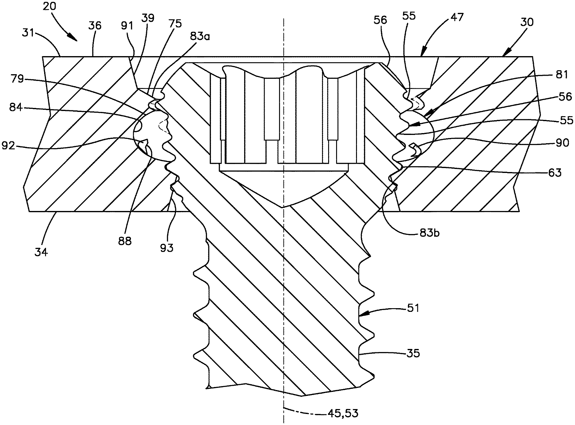
FIG. 5 is a sectional side elevation view of the portion of the bone plate illustrated in FIG. 2, shown with the bone screw illustrated in FIG. 1 being driven into the hole and producing shavings;
FIG. 6 is an enlarged perspective view of a portion of the bone plate illustrated in FIG. 1, showing a variable-angle locking hole;
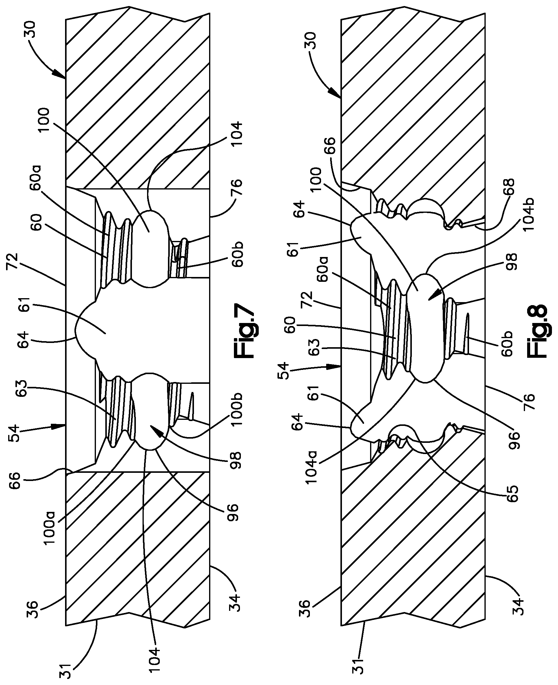
FIG. 7 is a to plan view of the portion of the bone plate illustrated in FIG. 7;
FIG. 8 is a sectional side elevation view of the portion of the bone plate illustrated in FIG. 7, taken along line 8-8;
FIG. 9 is another sectional side elevation view of the portion of the bone plate illustrated in FIG. 7, taken along line 9-9; and
FIG. 10 is a sectional side elevation view of the portion of the bone plate illustrated in FIG. 9, but shown with the variable-angle bone screw illustrated in FIG. 1 being driven into the variable-angle screw hole and producing shavings.
DETAILED DESCRIPTION
The present disclosure can be understood more readily by reference to the following detailed description taken in connection with the accompanying figures and examples, which form a part of this disclosure. It is to be understood that this disclosure is not limited to the specific devices, methods, applications, conditions or parameters described and/or shown herein, and that the terminology used herein is for the purpose of describing particular embodiments by way of example only and is not intended to be limiting of the scope of the present disclosure. Also, as used in the specification including the appended claims, the singular forms "a," "an," and "the" include the plural, and reference to a particular numerical value includes at least that particular value, unless the context clearly dictates otherwise.
The term "plurality", as used herein, means more than one. When a range of values is expressed, another embodiment includes from the one particular value and/or to the other particular value. Similarly, when values are expressed as approximations, by use of the antecedent "about," it will be understood that the particular value forms another embodiment. All ranges are inclusive and combinable.
Referring initially to FIG. 1, a bone fixation system 20 is configured to be implanted onto bone 22 so as to stabilize a first bone segment 24 with respect to a second bone segment 26 that is separated from the first bone segment 24 by a defect 28. In one example, the first bone segment 24 can be defined by the diaphysis of the bone, while the second bone segment 26 can be defined by the epiphysis of the bone. It should be appreciated, however, that the first and second bone segments 24 and 26 can be defined by any region of the bone 22 as desired. Further, the bone 22 can be any bone in the human or animal anatomy suitable for bone plate fixation. Further still, while the bone 22 is illustrated having first and second bone segments 24 and 26, it is appreciated that the bone 22 can include any number of defects or bone fragments as desired that are configured for fixation using the bone fixation system 20. For instance, the diaphysis of the bone can include a plurality of bone fragments.
The bone fixation system 20 can include a bone plate 30 and a plurality of bone anchors 32 that are configured to fix the bone plate 30 to the underlying bone 22, and in particular to each of the first and second bone segments 24 and 26. The bone anchors 32 include a head 33 and a shaft 35 that extends out with respect to the head 33 along a respective central axis 53. The shaft 35 can extend directly from the head 33, or can extend from a neck that is disposed between the head 33 and the shaft 35. The shaft 35 can be threaded, such that the bone anchor 32 is configured as a bone screw 37 whose shaft 35 extends out relative to the head 33 along the central axis 53, which can also be referred to as a central screw axis 53.
The threaded shaft 35 can be configured to threadedly purchase in the underlying bone 22. For instance, one or more up to all of the bone screw 37 can be configured as a cortical screw whose threaded shaft 35 is designed and configured to threadedly mate to cortical bone. Alternatively or additionally, one or more of the bone screws 37 can be configured as a cancellous screw whose threaded shaft 35 is designed and configured to threadedly mate to cancellous bone. It is appreciated that cancellous bone screws typically have threads that have a greater pitch than threads of cortical bone screws. Further, the threads of cancellous bone screws typically extend out from the shaft of the bone screw a greater distance than the threads of cortical bone screws.
The bone plate 30 defines a bone plate body 31. The bone plate body 31, and thus the bone plate 30, defines a bone-facing inner surface 34 configured to face the underlying bone 22, and an outer surface 36 that is opposite the inner surface 34 along a transverse direction T. The bone plate 30 further defines a plurality of fixation holes 38 that extend through the bone plate body 31 from the inner surface 34 to the outer surface 36. In particular, each of the fixation holes 38 extends through the bone plate body 31, and thus through the bone plate 30, along a respective central hole axis 45. The central hole axis 45 is oriented along an axial direction. The axial direction can be coincident with the transverse direction T. Thus, the central hole axis 45 can be oriented normal to each of the inner surface 34 and the outer surface 36. It should be appreciated, of course, that the axial direction defined by the central hole axis 45 can be oriented in any suitable direction as desired, including a direction oblique to the transverse direction T.
The fixation holes 38 are each sized to receive the shaft 35 of a respective one of the bone screws 37. The bone screws 37 that extend through fixation holes 38 are permanent bone screws, meaning that they remain after completion of the surgical procedure. This is distinguished from temporary fixation holes that, for instance, can be configured to receive temporary fixation members, such as Kirschner wires that are removed prior to completion of the surgical procedure. In this regard, the fixation holes 38 can be referred to as permanent fixation holes. Accordingly, during operation, the shaft 35 of the bone screw 37 can be inserted through a respective one of the fixation holes 38 and into the underlying bone 22. The bone screw 37 can then be rotated so as to cause the threaded shaft 35 to be driven into the underlying bone 22 as the threaded shaft 35 threadedly purchases with the underlying bone. The threaded shaft 35 can be driven into the underlying bone 22 until the head 33 engages the bone plate 30. The heads 33 of the bone screws 37 can engage the bone plate 30 in various different manners as will now be described.
For instance, certain ones of the fixation holes 38 can be unthreaded compression fixation holes 52, while certain others of the fixation holes 38 can be threaded locking holes 44. Still other ones of the fixation holes 38 can be a combination hole, whereby a threaded locking hole 44 and an unthreaded compression hole 52 intersect each other to define a combination hole.
Thus, one or more of the bone screws 37 can be configured as a compression screw 49 whose head 33 defines a compression head 58 that is configured to bear against the bone plate 30 in the compression hole 52 so as to apply a compressive force against the bone plate 30 toward the underlying bone 22. In particular, the bone plate 30 can define an internal compression surface 57 that can extend between the outer surface 36 and the inner surface 34 so as to at least partially define the compression hole 52. During operation, the shaft 35 of the compression screw 49 can be inserted through the compression hole 52 and driven into the underlying bone 22 as described above. In particular, rotation of the bone screw 37 causes the compression head 58 to compress against the internal compression surface 57. As a result, the compression head 58 causes the bone plate 30 to apply a compressive force against the underlying bone. At least a portion of the internal compression surface 57 is typically spherical or otherwise tapered with respect to the central hole axis 45 as it extends in an axially inward direction from the outer surface 36 toward the inner surface 34. The taper of the internal compression surface 57 prevents the compression head 58 from passing completely through the compression hole 52. The compression head 58 typically has an unthreaded external surface. Similarly, at least a portion up to an entirety of the internal compression surface 57 that abuts the unthreaded external surface of the compression head 58 is typically unthreaded. Thus, it is common to drive compression screws 49 into the unthreaded compression holes 52.
With continuing reference to FIG. 1, the bone plate 30 can alternatively or additionally define at least one or more threaded locking holes 44 that are each configured to threadedly purchase with a respective one of the bone screws 37. For instance, the bone plate 30 can define a plurality of threaded internal locking surfaces 65 that can extend from the bone-facing inner surface 34 to the outer surface 36. Thus, the threaded internal locking surfaces 65 can at least partially define respective ones of the locking holes 44.
Thus, at least one or more of the bone screws 37 can be configured as locking screws 41 that are configured to threadedly purchase with the bone plate 30 inside the threaded locking holes 44. In particular, the locking screws 41 can include an externally threaded locking screw head 69 that is configured to threadedly mate with a respective one of the threaded internal surfaces 65 of the bone plate 30 inside the respective locking hole 44. During operation, the shaft 35 of the locking screw 41 can be inserted through the fixation hole 38 and driven into the underlying bone 22 as described above. In particular, rotation of the screw 37 causes the threaded head 69 to threadedly mate with the threaded locking hole 44. As a result, the threaded screw head 69 fastens the bone plate 30 to the underlying bone 22 without applying a compressive force onto the bone plate 30 against the underlying bone 22. The bone plate 30 can be spaced from the underlying bone 22 when the threaded head 69 is threadedly mated with the threaded internal surface 65. Alternatively, the bone plate 30 can abut the underlying bone 22 when the threaded head 69 is threadedly mated with the threaded internal surface 65. At least a portion of the threaded internal surface 65 is typically tapered with respect to the central hole axis 45 as it extends in the axially inward direction from the outer surface 36 toward the inner surface 34. The taper of the threaded internal surface 65 is configured to prevent the threaded head 69 from passing completely through the threaded locking hole 44. Because the bone plate 30 can include both compression fixation holes 52 and threaded locking holes 44, the bone plate 30 can be referred to as a locking compression plate.
Alternatively or additionally, one more of the locking screws 41 can be configured as a standard-type locking bone screw 51. The externally threaded head 69 of the standard-type locking bone screw 51 can be configured as a standard-type threaded locking head 56. In particular, the standard-type threaded locking head 56 defines an external surface 55 and at least one helical thread 63 that extends from the external surface 55. The external surface 55 can be conically tapered or alternatively shaped as desired. The at least one thread 63 can be configured as a single lead thread, a double lead thread, or any number of leads as desired. The thread 63 extends greater than one full revolution about the central screw axis 53 so as to be configured to threadedly purchase with the standard-type locking head 56. Correspondingly, one or more of the threaded locking holes 44 can be configured as standard-type locking hole 47. In particular, the standard-type locking head 56 is configured to threadedly mate with the bone plate 30 in the standard-type locking hole 47 when the central screw axis 53 of the standard-type locking bone screw 51 is oriented at a predetermined orientation with respect to the central hole axis 45. For instance, the standard-type locking head 56 is configured to threadedly mate with the threaded internal surface 65 in the standard-type locking hole 47.
The predetermined orientation can be a nominal orientation whereby the central screw axis 53 is coincident with the central hole axis 45. Alternatively, the predetermined orientation can be defined when the central screw axis 53 is oriented oblique to the central hole axis 45. In certain examples, the standard-type locking screw 51 is configured to threadedly mate with the bone plate 30 in the standard-type locking hole 47 only when the bone screw 51 is oriented at the predetermined orientation. In one example, at least one or more up to all of the fixation holes 38 in the plate head portion can be configured as standard-type locking holes 47.
Alternatively or additionally, one more of the locking screws 41 can be configured as a variable angle (VA) locking bone screw 43. The externally threaded head 69 of the VA locking screw 43 can be configured as a VA threaded locking head 59. Correspondingly, one or more of the threaded locking holes 44 can be configured as variable angle (VA) locking holes 54. In particular, the VA threaded head 59 is configured to threadedly mate with the bone plate 30 in the VA locking holes 54 when the central screw axis 53 of the VA bone screw 43 is oriented at any one of a plurality of angles within a range of angles with respect to the central hole axis 45 at which the VA threaded head 59 is configured to threadedly mate with the bone plate 30 in the VA locking hole 54. For instance, the VA locking head 59 is configured to threadedly mate with the threaded internal surface 65 in the VA locking hole 54. In one example, at least one or more up to all of the fixation holes 38 in the plate head portion can be configured as VA locking holes 54.
The bone plate 30 and the locking screws 41 can each comprise one or more biocompatible materials, such as titanium, titanium alloys (e.g., titanium-aluminum-niobium (TAN) alloys, such as Ti-6Al-7Nb), stainless steel, cobalt base alloys, composite materials, and polymeric materials and/or ceramic materials, by way of non-limiting examples. In one example, the material of the locking screws 41 can have a hardness that is greater than that of the bone plate 30. For instance, the bone plate 30 can primarily or entirely be made of titanium, and the locking screws 41 can primarily or entirely comprise Ti-6Al-7Nb (TAN). Alternatively, the hardness of the bone plate 30 can be greater than that of the locking screws 41. Alternatively, the hardness of the bone plate 30 can be equal to that of the locking screws 41.
While the bone plate 30 has been described in accordance with one specific example, it should be appreciated that the bone plate 30 can be configured in any suitable manner as desired. Further, bone plates 30 constructed in accordance with any of the examples described herein can be configured to attach to any region or region or regions of any suitable bone in the human or animal anatomy suitable for bone plate fixation.
The present inventors recognize that misalignment of the threaded locking heads 69 of locking screws 41 with the internal locking surface 65 can result in cross-threading between the threaded locking heads 69 and the internal locking surface 65. Cross-threading can occur when the threads of the threaded locking heads 69 of the locking screw do not fit appropriately with the threads of the internal locking surface 65 within the locking holes 44. Cross-threading is problematic because it can reduce the interference fit (also referred to as the "form-fit") between the threads of the locking heads 69 with the threads of the internal locking surface 65, which can result in the production of shavings as the locking head 69 is threadedly mated with the internal locking surface 65.
For instance, when the threaded locking head 69 is harder than the internal locking surface 65, cross-threading can cause the locking screw 41, and in particular the threaded locking heads 69, to shave material from the bone plate 30, and in particular the internal locking surface 65, thereby creating shavings of the bone plate 30, and in particular of the internal locking surface 65. Alternatively, when the internal locking surface 65 is harder than the threaded locking head 69, cross-threading can cause the bone plate 30, and in particular the internal locking surface 65, to shave material from the locking screw 41, and in particular the threaded locking head 69, thereby creating shavings of the locking screw 41, and in particular of the threaded locking head 69. Alternatively still, when the internal locking surface 65 has a hardness substantially equal to that of the threaded locking head 69, cross-threading can cause one or both of 1) the locking screw 41, and in particular the threaded locking heads 69, to shave material from the bone plate 30, and in particular the internal locking surface 65, thereby creating shavings of the bone plate 30, and in particular of the internal locking surface 65, and 2) the bone plate 30, and in particular the internal locking surface 65, to shave material from the locking screw 41, and in particular the threaded locking head 69, thereby creating shavings of the locking screw 41, and in particular of the threaded locking head 69.
As will now be described with respect to the standard-type locking hole 47, the bone plate 30 is configured to capture shavings that are produced when threadedly mating the locking screw 41 to the bone plate 30.
The standard-type locking hole 47 and the standard-type locking bone screw 51 will now be described in more detail with respect to FIGS. 1-5 generally. With initial reference to FIGS. 1-4, the threaded internal locking surface 65 of the standard-type locking hole 47 can include an internal standard-type locking surface 71 and at least one helical thread 75 that extends out from the standard-type internal locking surface 71. Thus, the locking surface 71 can define at least one threaded surface 83. The at least one thread 75 can extend out from the threaded surface 83 in the locking hole 47. The at least one helical thread 75 is continuous along greater than one revolution about the central hole axis 45. Thus, the at least one helical thread 75 can be referred to as a standard-type helical thread. The at least one thread 75 can be configured as a single lead thread, a double lead thread, or any number of leads as desired. Otherwise stated, the bone plate body 31, and thus the bone plate 30, can include the internal standard-type locking surface 71 that at least partially defines the standard-type locking hole 47. For instance, the standard-type locking surface 71 can extend along the axial direction.
In this regard, the axial direction is used herein as a bi-directional term that includes both an axially inward direction from the outer surface 36 to the inner surface 34 of the bone plate 30, and an axially outward direction from the inner surface 34 to the outer surface 36. Thus, the directional term "axially inward" and derivatives thereof as used herein refers to a direction from the outer surface 36 toward the inner surface 34. Conversely, the terms "axially outward" and derivatives thereof as used herein refers to a direction from the inner surface 34 toward the outer surface 36. The axial direction, including the axially inward and axially outward directions, can be oriented along the central hole axis 45. Alternatively, the axial direction, including the axially inward and axially outward directions, can be oriented along a direction oblique to the central hole axis 45, for instance when used with reference to the locking surfaces 65 of the bone plate 30, and in particular the standard-type locking surface 71.
It should be appreciated that the description herein of the standard-type locking surface 71 and at least one thread 75 of the standard-type locking hole 47 can apply more generically with equal weight and effect to the threaded internal surface 65 of the threaded locking hole 44. The standard-type locking hole 47 is further configured to threadedly mate with the standard-type threaded head 56 of the standard-type locking bone screw 51. That is, the at least one thread 75 of the threaded internal standard-type locking surface 71 can threadedly purchase with the threaded at least one thread 63 of the external surface 55 of the head 56 of the standard-type locking screw 51. The central screw axis 53 of the standard-type locking screw 51 is at a predetermined orientation with respect to the central hole axis 45 of the standard-type locking hole 47, and at no other orientations with respect to the central hole axis 45. The predetermined orientation can be achieved when the central screw axis 53 is substantially coincident with or oblique to the central hole axis 45.
The external thread 63 of the external surface 55 of the head 56 of the standard-type locking screw 51 can be circumferentially continuous about the central screw axis 53. It should be appreciated, however, that the head 56 can be alternatively constructed in any manner desired so as to threadedly mate with the at least one thread 75 in the manner described herein. In one example, the external surface 55 of the head 56 of the standard-type locking screw 51 can be tapered radially inwardly as it extends along the axially inward direction. For instance, the external surface 55 of the head 56 of the standard-type locking screw 51 can be tapered linearly. Thus, the head 56 of the standard-type locking screw 51 can be conical in shape.
In this regard, the radial direction is used herein as a bi-directional term that includes both a radially inward direction toward the central hole axis 45, and a radially outward direction away from the central hole axis 45. Thus, the directional term "axially inward" and derivatives thereof as used herein refers to a direction toward the central hole axis 45. Conversely, the terms "radially outward" and derivatives thereof as used herein refer to a away from the central hole axis 45. The radial directions can be oriented perpendicular to the central hole axis 45, or can be oblique to the central hole axis 45.
The linear taper can define any suitable slope with respect to the central screw axis 53. The slope of the head 56 can be between 5 degrees and 25 degrees. For instance, the slope of the head 56 can be approximately 10 degrees. The terms "approximately" and "substantially" as used herein with respect to dimensions and angles takes into account manufacturing tolerances. Further, the terms "approximately" and "substantially" can include 10% greater than or less than the stated dimension or angle. Further, the terms "approximately" and "substantially" can equally apply to the specific value stated. The slope of the head 56 can extend along the crests of the at least one external thread 63. Alternatively or additionally, the slope of the head 56 can extend along the roots of the at least one external thread 63.
Referring now to FIGS. 3 and 4 in particular, the bone plate body 31, and thus the bone plate 30, can define a collection cavity 79. The collection cavity 79 interrupts the at least one thread 75 of the internal locking surface 71 along the axial direction. Thus, a first portion of the at least one thread 75 can extend axially outward with respect to the collection cavity 79, and a second portion of the at least one thread 75 can extend axially inward with respect to the collection cavity 79. The collection cavity 79 is configured to collect shavings that may be produced while the at least one thread 63 of the standard-type locking head 56 threadedly purchases with the at least one thread 75 of the internal surface 71 in the manner described above.
In one example, the collection cavity 79 can be configured as a collection recess 81 that is swept circumferentially about the central hole axis 45. In particular, the collection recess 81 can extend circumferentially alone or in combination with an axial directional component. The internal surface 71 defines a recessed collection surface 84 that is recessed radially outward with respect to the at least one threaded surface 83 so as to define the collection recess 81. The recessed collection surface .84 extends radially outward away from the central hole axis 45 with respect to the at least one threaded surface 83 so as to interrupt the at least one thread 75 along the axial direction. In one example, the recessed collection surface .84 can be unthreaded. The collection recess 81 can be configured in any manner as desired. In one example, the recessed collection surface .84 can be unthreaded and smooth.
The recessed collection surface 84, and thus the collection recess 81, can extend circumferentially along a circumferential length so as to divide at least a portion of the at least one thread 75 into a first or axially outer thread segment 75a, and a second or axially inner thread segment 75b. Accordingly, the recessed collection surface .84, and thus the collection recess 81, can divide the threaded surface 83 into a first or axially outer threaded surface segment 83a that carries the axially outer thread segment 75a, and a second or axially inner threaded surface segment 83b that carries the second thread segment 75b. The outer thread segment 75a and the inner thread segment 75b can lie along a common helical path. That is, the outer thread segment 75a lies along a respective outer helical path, the inner thread segment 75b lies along a respective inner helical path, and the outer helical path can be helically aligned with the inner helical path along the common helical path. Alternatively, the outer and inner thread segments 75a and 75b can lie on different helical paths that are parallel to each other. In one example, the collection surface 84, and thus the collection recess 81, can define an axial length greater than the pitch of each of the outer thread segment 75a and the inner thread segment 75b. For instance, the collection surface 84, and thus the collection recess 81, can define an axial length at least twice the pitch of each of the outer thread segment 75a and the inner thread segment 75b.
In one example, the circumferential length of the recessed collection surface .84, and thus of the collection recess 81, can extend at least 90 degrees circumferentially about the central hole axis 45. For instance, the circumferential length can extend at least 180 degrees about the central hole axis 45. In one example, the circumferential length can extend a full 360 degree revolution about the central hole axis 45. The recessed collection surface .84, and thus the collection recess 81, can extend continuously and uninterrupted along an entirety of the circumferential length about the central hole axis 45. Alternatively, it should be appreciated that the collection recess 81 can be segmented into one or more circumferential segments having circumferentially opposed terminal ends.
Referring now to FIGS. 3-4, the recessed collection surface .84 can define a first or axially outer end 84a, and a second or axially inner end 84b opposite the axially outer end 84a. The axially outer end 84a can define an interface with the axially outer threaded surface segment 83a, and the radially inner end 84b can define an interface with the axially inner threaded surface segment 83b. At least a portion of the recessed collection surface .84, up to an entirety of the recessed collection surface .84, can be concave along a plane that includes the central hole axis 45. For instance, the recessed collection surface .84 can be curved along the plane, though the recessed surface can define any suitable alterative shape along the plane as desired. Because at least a portion of the locking surface tapers radially inward as it extends axially inward, the axially inner end 84b can be offset with respect to the axially outer end 84a along the radially inward direction toward the central hole axis 45.
Further, the recessed collection surface .84 can be oriented along a respective plane that is oriented perpendicular to the central hole axis 45. Thus, the respective plane can intersect the helical path defined by the axially outer and inner thread segments 75a and 75b. For instance, an entirety of the axially outer end 84a can lie on a respective plane that is oriented perpendicular to the central hole axis 45. Further, the axially outer end 84a can extend along a circular path in the respective plane. Thus, in one example, the axially outer end 84a can be spaced a constant distance from the central hole axis 45 along the radial direction along an entirety of the length of the collection recess 81. Alternatively or additionally, an entirety of the axially inner end 84b can lie on a respective plane that is oriented perpendicular to the central hole axis 45. Further, the axially inner end 84b can extend along a circular path in the respective plane. Thus, in one example, the axially inner end 84b can be spaced a constant distance from the central hole axis 45 along the radial direction along an entirety of the length of the collection recess 81. Alternatively or additionally still, an entirety of a midline 86 of the recessed collection surface .84 can lie on a respective plane that is oriented perpendicular to the central hole axis 45. Further, the midline 86 can extend along a circular path in the respective plane. Thus, in one example, the midline 86 can be spaced a constant distance from the central hole axis 45 along the radial direction along an entirety of the length of the collection recess 81. The midline 86 can be equidistantly spaced between the radially outer end 84a and the radially inner end 84b. The midline 86 can define a radial depth that is spaced radially further from the central hole axis 45 than any other location of the recessed collection surface .84. Further, the radial depth of the collection recess 81 can be greater than the maximum height of the thread segments 75a and 75b.
The internal locking surface 71 can include a tapered lead-in surface 91 at the axially outer end of the standard-type locking hole 47. Further, the internal surface 71 can include a tapered undercut surface 93 at the axially inner end of the standard-type locking hole 47. The lead-in surface 91 can flare radially outward as it extends in the axially outward direction. The lead-in surface 91 can further be devoid of threads, and can be smooth. The lead-in surface 91 can extend circumferentially about the axially outer end of the standard-type locking hole 47. In one example, the lead-in surface 91 can extend circumferentially continuously and uninterrupted along a full revolution about the central hole axis 45. For instance, the lead-in surface 91 defines an axially outer end at the outer surface 36 of the bone plate 30. The lead-in surface 66 thus extends axially inward from its axially outer end to its axially inner end. The axially inner end of the lead-in surface 91 can be define an interface with the axially outer threaded surface segment 83a, and thus with the axially outer thread segment 75a.
The undercut surface 93 can flare radially outward as it extends in the axially inward direction. The undercut surface 93 can further be devoid of threads, and thus can be smooth. The undercut surface 93 can extend circumferentially about the axially inner end of the standard-type locking hole 47. In one example, the undercut surface 93 can extend circumferentially continuously and uninterrupted along a full revolution about the central hole axis 45. For instance, the undercut surface 93 can extend axially outward from the inner surface axially inner threaded surface segment 83b, and thus from the axially inner thread segment 75b. The undercut surface 93 can define an average diameter that is less than that of the lead-in surface 91.
Referring now to FIG. 5, the collection cavity 79, and thus the collection recess 81, can be configured to collect at least one shaving 88 that can be produced, for instance when the at least one external thread 63 of the head 56 of the standard-type locking screw 51 cross-threads with the at least one thread 75 of the bone plate 30 as the standard-type locking screw 51 is driven into the standard-type locking hole 47. For instance, when the threaded head 56 of the standard-type locking screw 51 is harder than the internal standard-type locking surface 71, cross-threading can cause the standard-type locking screw 51, and in particular the threaded heads 56, to shave material from the bone plate 30, such as from one or both the internal surface 71 and the at least one thread 75. The shaved material from the bone plate 30 can be referred to as plate shavings 90. Thus, the at least one shaving 88 can include one or more plate shavings 90.
It is envisioned that cross-threading can occur at the interface between the standard-type locking surface 71 and the external surface 55 of the threaded locking head 56. In particular, cross-threading can occur at the interface between the axially outer threaded surface segment 83a, such as the axially outer thread segment 75a, and the external surface 55 of the threaded locking head 56, for instance at the external thread 63. Alternatively or additionally, cross-threading can occur at the interface between the axially inner threaded surface segment 83b, such as the axially inner thread segment 75b, and the external surface 55 of the threaded locking head 56, for instance at the external thread 63. Therefore, plate shavings 90 can be produced from the threaded surface 83, for instance at the axially outer thread segment 75a. For instance, plate shavings 90 can be produced from the axially outer threaded surface segment 83a, such as the axially outer thread segment 75a. Alternatively or additionally, plate shavings 90 can be produced from the axially inner threaded surface segment 83b, such as the axially inner thread segment 75b.
Without being bound by theory, it is envisioned that plate shavings 90 produced from the axially outer threaded surface segments 83a can be driven axially, for instance, axially inwardly along the helical path, as the threaded head 56 travels axially inwardly along the helical path. In particular, when the plate shavings 90 are freely slidable with respect to the locking head 56, the plate shavings 90 can be driven axially inwardly into the collection recess 81, and thus the collection cavity 79. Further, without being bound by theory, it is envisioned that the plate shavings 90 produced from the axially inner threaded surface segments 83b can be driven axially outward, for instance along the helical path, as the threaded head 56 travels axially inward along the helical path. In particular, when the plate shavings 90 are broken off from the plate 30 and/or are pinched between the locking head 56 and the plate 30, and thus not freely slidable with respect to the locking head 56, the plate shavings 90 can be driven axially outwardly into the collection recess 91, and thus the collection cavity 79. Alternatively, if the plate shavings 90 produced from the axially inner threaded surface segments 83b are driven axially inward, then the plate shaving 90 would exit the bone plate at the bone-facing surface of the bone plate. Accordingly, the shaving is prevented from traveling to the soft tissue that may reside at a location adjacent the outer surface 36 of the bone plate 30.
As a result, at least one or more plate shavings 90 can be captured radially between the recessed collection surface 84 and the threaded head 56. Thus, the at least one captured plate shaving 90 is prevented from traveling out of the standard-type locking hole 47 of the bone plate 30 and into surrounding soft tissue, and can further be removed from the threaded interface between the threaded head 56 and the internal locking surface 71.
Alternatively, the bone plate 30 can be harder than the standard-type locking screw 51. Thus, the internal standard-type locking surface 71 can be harder than the threaded head 56 of the standard-type locking screw 51. Accordingly, cross-threading can cause one or both of the internal standard-type locking surface 71 and the at least one thread 75 to shave material from the standard-type locking screw 51, and in particular from one or both of the external surface 55 and at least one helical thread 63 of the standard-type threaded head 56. The shaved material from the standard-type locking screw 51 can be referred to as screw shavings 92. Thus, the at least one shaving 88 can include one or more screw shavings 92.
As described above, is envisioned that cross-threading can occur at the interface between the standard-type locking surface 71 and the external surface 55 of the threaded locking head 56. In particular, cross-threading can occur at the interface between the axially outer threaded surface segment 83a, such as the axially outer thread segment 75a, and the external surface 55 of the threaded locking head 56, for instance at the external thread 63. Alternatively or additionally, cross-threading can occur at the interface between the axially inner threaded surface segment 83b, such as the axially inner thread segment 75b, and the external surface 55 of the threaded locking head 56, for instance at the external thread 63.
Without being bound by theory, it is envisioned that screw shavings 92 can be driven axially, for instance axially inward along the helical path, as the threaded head 56 travels axially inward along the helical path. In particular, when the screw shavings 92 are broken off from the external surface 55, such as at the at least one thread 63, and/or are pinched between the locking head 56 and the plate 30, and thus not freely slidable with respect to the plate 30, the screw shavings 92 can be driven axially inward. Thus, screw shavings 92 produced at a location axially outward of the collection cavity can be driven axially inward into the collection recess 81, and thus the collection cavity 79. Further, without being bound by theory, it is envisioned that screw shavings 92 can be driven axially, for instance axially outward along the helical path, as the threaded head 56 travels axially inward along the helical path. In particular, when the screw shavings 92 are freely slidable with respect to the threaded internal surface 65 of the bone plate 30, the screw shavings 92 can be driven axially outward. Thus, screw shavings 92 produced at a location axially inward of the collection cavity 79 can be driven axially outward into the collection recess 81, and thus the collection cavity 79. Accordingly, the screw shaving 92 is captured radially between the recessed collection surface .84 and the threaded head 56. Alternatively, if the screw shavings 92 produced at the location axially inward of the collection cavity 79 travel axially inward, then the screw shavings 92 would exit the bone plate at the bone facing inner surface 34. Thus, the screw shaving 92 is prevented from traveling through the bone plate 30 at the outer surface 36 and is thus prevented from traveling to the surrounding soft tissue. It should also be appreciated that the screw shaving 92 is removed from the threaded interface between the threaded head 56 and the internal locking surface 71.
Alternatively still, when the internal standard-type locking surface 71 has a hardness substantially equal to that of the threaded locking head 56, cross-threading can cause one or both of 1) the standard-type locking screw 51, and in particular the threaded locking head 56, to shave material from the bone plate 30 so as to produce the plate shaving 90 and 2) the bone plate 30, and in particular the internal standard-type locking surface 71, to shave material from the standard-type locking screw 51, and in particular from the threaded locking head 56, so as to produce the screw shaving 92. The shavings 90 and 92 can travel into the collection cavity 79 or out the inner bone-facing surface 34 in the manner described above. Thus, it is appreciated that the at least one shaving 88 can include one or more plate shaving 90 and no screw shavings 92, one or more screw shaving 92 and no plate shavings, or a combination of one or more plate shaving 90 and one or more screw shaving 92.
As described above, while the standard-type locking hole 47 can include the collection cavity 79 that is configured to retain at least some of the shavings that are produced when the head 56 of the standard-type locking screw 51 is threadedly mated to the bone plate 30, it is recognized that the variable angle locking hole 54 can further include the collection cavity 79. The collection recess 81, and thus the collection cavity 79, can be positioned anywhere along the internal surface 71 of the bone plate 30 as desired. For instance, in one example, the collection recess 81 can be positioned such that the internal surface 71 defines at least one revolution of the at least one thread 75 between the collection recess 81 and the outer surface 36 of the bone plate 30. Alternatively or additionally, the collection recess 81 can be positioned such that the internal surface 71 defines at least one revolution of the at least one thread 75 between the collection recess 81 and the inner surface 34 of the bone plate 30.
The VA locking hole 54 will now be described in more detail with respect to FIGS. 6-9. The threaded internal locking surface 65 of the VA locking hole 54 can be referred to as a threaded internal surface 39, which can be configured as an internal variable angle locking surface. The internal surface 39 of the bone plate 30 extends from the outer surface 36 to the inner surface 34 so as to define the VA locking hole 54 that extends from the outer surface 36 to the inner surface 34. In particular, the VA locking hole 54 extends along the central hole axis 45. The central hole axis 45 can be oriented along the transverse direction T. Thus, the central hole axis 45 can be oriented normal to each of the inner surface 34 and the outer surface 36. It should be appreciated, of course, that the central hole axis 45 can be oriented in any suitable direction as desired, including a direction oblique to the transverse direction T.
The internal surface 39, and thus the bone plate 30, can define a plurality of threaded regions 62 that carry at least one thread 46. The internal surface 39, and thus the bone plate 30, can further define a plurality of relief regions 64 that are disposed circumferentially between respective adjacent ones of the threaded regions 62. Thus, the threaded regions 62 and the relief regions 64 can be alternatingly arranged with each other circumferentially about the central hole axis 45. The threaded regions 62 and the relief regions 64 are configured such that the VA locking screws 43 are configured to threadedly purchase with the internal surface 39 at the threaded regions 62 without threadedly purchasing with the internal surface 39 at the relief regions 64.
In one example, the at least one thread 46 projects out from the internal surface 39 at the threaded regions 62 into the VA locking hole 54 generally toward the central hole axis 45. The at least one thread 46 can be monolithic with the internal surface 39. The at least one thread 46 can extend along a thread path. The thread path can be a helical thread path. In one example, the at least one thread 46 can be a single lead thread, a double lead thread, or any suitably constructed thread as desired. The internal surface 39 can further define a recess such as a relief recess 48 at each of the relief regions 64. The relief recesses 48 can circumferentially interrupt the at least one thread 46 so as to define a plurality of thread segments 60 of the at least one thread 46. Axially aligned ones of the thread segments can combine to define a plurality of threaded columns 50. Thus, it can be said that the threaded columns 50 are defined by thread segments 60. Because the at least one thread 46 can extend along a helical thread path, the threaded columns 50 can have different numbers of thread segments 60. The relief recesses 48 and the columns 50 can be alternatingly arranged with each other circumferentially about the central hole axis 45. The at least one relief recess 48 is offset with respect to the columns 50 of thread segments 60 in a radially outward direction. The internal surface 39 can be said to define a relief surface 61 that at least partially defines the relief recesses 48.
The axial direction is defined as a direction between the outer surface 36 and the inner surface 34 of the bone plate 30. Thus, the directional term "axially inward" and derivatives thereof as used herein refers to a direction from the outer surface 36 toward the inner surface 34. Conversely, the terms "axially outward" and derivatives thereof as used herein refers to a direction from the inner surface 34 toward the outer surface 36. The axial direction, including the axially inward and axially outward directions, can be oriented along the central hole axis 45. Alternatively, the axial direction, including the axially inward and axially outward directions, can be oriented along a direction oblique to the central hole axis 45, for instance when used with reference to the locking surfaces 65 of the bone plate 30, and in particular the internal VA locking surface 39.
The relief recesses 48 can have a radial depth sufficient such that the relief surface 61 is recessed with respect to the internal surface 39 at the columns 50 along the radially outward direction. That is, the relief surface 61 can define a radial distance from the central hole axis 45 that is greater than the radial distance from the central hole axis 45 to the major diameter of the at least one thread 46 of the columns 50. Therefore, during operation, the VA screw head 59 of the VA locking bone screw 43 that threadedly purchases with the internal surface 39 at the columns 50 of thread segments 60 are spaced radially inward from the internal surface 39 at the relief recess 48. The relief surfaces 61 can be devoid of the thread 46. For instance, the relief surfaces 61 can be unthreaded and smooth. The thread segments 60 of each of the columns 50 are spaced from each other in the axial direction so as to define interstices that receive corresponding external threads 94 of the VA screw head 59.
The thread segments 60 of each of the columns 50 can be circumferentially offset from the thread segments 60 of the other ones of the columns 50. Further, adjacent ones of the circumferentially spaced thread segments 60 can be separated by a respective common one of the relief recesses 48. Thus the thread segments 60 of each column 50 can be aligned with the thread segments 60 of one or both adjacent column 50 along the thread path. Because the thread path can be helical, the thread segments 60 can be aligned with the thread segments 60 of an adjacent one of the columns 50 along a helical path. In one example, each of the thread segments 60 of a respective one of the columns 50 is aligned along the thread path with 1) one the thread segments 60 a first adjacent column 50, and 2) one the thread segments 60 of a second adjacent column 50. Thus, the respective one of the columns 50 is disposed circumferentially between the first adjacent column 50 and the second adjacent column 50. Further, the thread segments 60 of the respective one of the columns 50 is disposed between the first one of the thread segments 60 and the second one of the thread segments 60 with respect to the axial direction.
In one example, the bone plate 30 can include four recesses 48 and four columns 50. However, it is appreciated that the bone plate 30 can include any number of recesses 48, greater than one, as desired, and as many corresponding columns 50, greater than one, so as to define the variable angle locking hole 54 of the type described herein. Further, the relief recesses 48 can be substantially (within manufacturing tolerance) identical to each other. Similarly, the columns 50 can be substantially (within manufacturing tolerance) identical to each other. Thus, the relief recesses 48 can be circumferentially equidistantly spaced from each other about the central hole axis 45. Similarly, the columns 50 can be circumferentially equidistantly spaced from each other about the central hole axis 45. Alternatively, the relief recesses 48 can be circumferentially spaced from each other at a variable distance about the central hole axis 45. Similarly, the columns 50 can be circumferentially spaced from each other at a variable distance about the central hole axis 45.
In one example, the relief surface 61 extends along a circular path along the plane that is oriented normal to the central hole axis 45. Thus, the curvature can be defined by a radius that is swept in a plane oriented normal to the central hole axis 45. Further, the radius can be smaller than the radius from the central hole axis 45 to the internal surface 39. While the threaded regions 62 include respective columns 50 of threaded segments 60, it should be appreciated that the internal surface 39 need not be threaded along its entirety at locations axially aligned with the columns 50. For instance, the internal surface 39 can include a tapered lead-in surface 66 at the axially outer end of the VA locking hole 54. Further, the internal surface 39 can include a tapered undercut surface 68 at the axially inner end of the VA locking hole 54.
The lead-in surface 66 can flare radially outward as it extends in the axially outward direction. The lead-in surface 66 can further be devoid of threads. For instance, the lead-in surface 66 can be smooth. The lead-in surface 66 can extend circumferentially continuously and uninterrupted along a full revolution about the central hole axis 45. In one example, the lead-in surface 66 can define an axial length at locations aligned with the columns 50 that are greater than the axial length of the lead-in surface at locations aligned with the relief recesses 48. The lead-in surface 66 defines an axially outer end at the outer surface 36 of the bone plate 30. The lead-in surface 66 thus extends axially inward from its axially outer end to its axially inner end. At locations axially aligned with the columns 50, and thus axially aligned with the threaded regions 62, the axially inner end of the lead-in surface 66 can be defined by an axially outermost one of the thread segments 60 of the columns 50. At locations axially aligned with the relief surfaces 61, and thus axially aligned with the relief regions 64, the axially inner end of the lead-in surface 66 can be defined as an intersection between the lead-in surface 66 and the relief surface 61. The intersection can be defined at the axially outermost end of the relief surfaces 61.
The outer surface 36 of the bone plate 30 can define an axially outer perimeter 70 of an axially outer opening 72 to the VA locking hole 54. Thus, the lead-in surface 66 or segments of the lead-in surface 66 can axially inward from the perimeter 70. In one example, the perimeter 70 can define a circle, though it should be appreciated that the outer perimeter 70 can define different geometric shapes as desired. A circle may be preferable in some examples because, as described in more detail below, the VA locking screw 43 can threadedly purchase with the columns 50 at an angle relative to the central hole axis 45 within a range of angles at which the head 33 of the VA locking screw 43 can threadedly purchase with the columns 50. Thus, the outer perimeter 70 can surround a portion of the VA threaded head 59 when the VA threaded head 59 is purchased with the columns 50 at an angle within the range of angles. In one example, the relief surfaces 61 can extend from the inner surface 34 to the lead-in surface 66. The shaft can extend into the relief recesses when the VA locking screw 43 is angulated with respect to the central hole axis 45 and threadedly purchased with the bone plate 30 in the VA locking hole 54.
The undercut surface 68 can flare radially outward as it extends in the axially inward direction. The undercut surface 68 can further be devoid of the at least one thread 46. For instance, the undercut surface 68 can be smooth. The undercut surface 68 can extend circumferentially about the axially inner end of the VA locking hole 54 at locations aligned with the columns 50. Alternatively, the undercut surface 68 can extend circumferentially continuously and uninterrupted along a full revolution about the central hole axis 45. For instance, the undercut surface 68 can extend axially outward from the inner surface 34 of the bone plate 30. Thus, the undercut surface 68 has an axially inner end at the inner surface 34. The undercut surface 68 has an axially outer end opposite the axially inner end along the axial direction. At locations axially aligned with the columns 50, and thus axially aligned with the threaded regions 62, the axially outer end of the undercut surface 68 can be disposed at the axially innermost thread segment 60 of the columns 50.
The inner surface 34 of the bone plate 30 can define an axially inner perimeter of an axially inner opening 76 to the VA locking hole 54. In one example, the inner perimeter can define a circle, though it should be appreciated that the inner perimeter can define different geometric shapes as desired. A circle may be preferable in some examples because, as described in more detail below, a VA locking screw 43 can threadedly purchase with the columns 50 at an angle relative to the central hole axis 45 within a range of angles at which the VA threaded head 59 of the VA locking screw 43 can threadedly purchase with the columns 50. The range of angles can be disposed within a cone. Thus, the undercut surface 68 or segments of the undercut surface 68 can provide clearance for the screw shaft at different angles within the range of angles.
It should be appreciated that the columns 50 can extend from the lead-in surface 66 to the undercut surface 68. Further, the columns 50 can taper radially inward toward the central hole axis 45 as they extend axially inward. In one example, the columns 50 can extend linearly along the axially inward direction from the lead-in surface 66 to the undercut surface 68. Further, the VA locking hole 54 can be constructed such that no portion of the internal surface 39 extends radially inward of the columns 50. Therefore, the VA locking screw 43 described herein can threadedly purchase within the columns 50 without contacting any other surface except for the columns 50 and the undercut surface 68 when the VA locking screw 43 is fully angulated. The relief surfaces 61 can also extend from the lead-in surface 66 to the undercut surface 68. Further, the relief surfaces 61 can taper radially inward toward the central hole axis 45 as they extend axially inward. In one example, the relief surfaces 61 can extend linearly along the axial direction from the lead-in surface 66 to the undercut surface 68.
The VA locking hole 54 is configured to receive a the VA locking screw 43 that is configured to threadedly mate with the bone plate 30 in the VA locking hole 54 at different orientations with respect to the central hole axis 45. The VA threaded head 59 (see FIG. 1) can be constructed in accordance with any embodiment as described in U.S. Pat. No. 8,574,268, the disclosure of which is hereby incorporated by reference as if set forth in its entirety herein. Thus, it is appreciated that the VA threaded head 59 of the VA locking screw 43 can define an external surface and at least one external thread 78 that extends from the external surface. The VA threaded head 59 of the VA locking screw 43 have a curved outer surface, which can be convex in one example. In particular, the outer surface can be spherical. Further, the external thread 78 of the VA threaded head 59 of the VA locking screw 43 can be circumferentially continuous about the central screw axis 53. It should be appreciated, however, that the VA threaded head 59 can be alternatively constructed in any manner desired so as to threadedly mate with the at least one thread 46 in the manner described herein.
Otherwise stated, the VA locking screw 43 is configured to be inserted into the VA locking hole 54 such that the central screw axis 53 is at one of a plurality of angles with respect to the central hole axis 45 within a range of angles at which the VA threaded head 59 is configured to threadedly mate with the at least one thread 46 in the VA locking hole 54. For instance, the VA locking screw 43 is configured to be inserted into the VA locking hole 54 such that the central screw axis 53 is at one of a plurality of angles within a range of angles defined by the central screw axis 53 and the central hole axis 45 at which the VA threaded head 59 is configured to threadedly mate with each of the columns 50. The range of angles can be disposed within a cone that is centered about the central hole axis 45. Thus, the range of angles can be disposed within a cone of up to thirty degrees. The range of angles can be measured as 15 degrees with respect to the central hole axis 45. The central hole axis 45 can define the center of the cone. Thus, the VA threaded head 59 of the VA locking screw 43 can mate with the bone plate 30 in the manner described herein both when central screw axis 53 of the VA locking screw 43 is coincident with the central hole axis 45 and when the central screw axis 53 of the VA locking screw 43 is at any other angle with respect to the central hole axis 45 within the range of angles.
Thus, it can be said that the at least one thread 46 is configured to threadedly mate with the VA threaded head 59 while the VA locking screw 43 is inserted into the VA locking hole 54 such that the central screw axis 53 is oriented at a first angle with respect to the central hole axis 45, and the at least one thread 46 is further configured to threadedly mate with the VA threaded head 59 when the VA locking screw 43 is inserted into the VA locking hole 54 such that the central screw axis 53 is oriented at a second angle with respect to the central hole axis 45 that is different than the first angle. At least one or both of the first and second angles can be non-zero angles. Alternatively, the central screw axis 53 can be coincident with the central hole axis 45 in one of the orientations in the range of orientations.
Referring to FIG. 10, the VA locking hole 54 is configured to receive the VA locking screw 43 such that respective ones of the columns 50 threadedly purchase with the externally threaded VA threaded head 59 of the VA locking screw 43 when the central screw axis 53 and the central hole axis 45 define any angle within the range of angles that are disposed within the cone. Thus, the thread segments 60 of the columns 50 and the external thread 78 of the VA threaded head 59 of the VA locking screw 43 can be configured to threadedly purchase with each other. In one example, the external thread 78 of the VA threaded head 59 of the VA locking screw 43 defines a respective thread angle, and the thread segments 60 of the columns 50 define a respective thread angle. In one example, the thread angle of the thread segments 60 can be greater than the thread angle of the external thread 78 of the VA threaded head 59 of the VA locking screw 43. Alternatively, the thread angle of the thread segments 60 can be less than the thread angle of the external thread 78 of the VA threaded head 59 of the VA locking screw 43. Alternatively still, the thread angle of the thread segments 60 can be substantially equal to the thread angle of the external thread 78 of the VA threaded head 59 of the VA locking screw 43.
The at least one thread 46 of the VA hole 54 and the at least one external thread 78 of the VA threaded head 59 are defined prior to insertion of the VA locking screw 43 into the VA locking hole 54. That is, the internal surface 39 is not designed or configured to cut or form threads into the VA threaded head 59. Similarly, the VA threaded head 59 is not designed or configured to cut or form threads into the internal surface 39. It is contemplated, however, as described above, that in the event of cross-threading while locking the VA locking screw 43 in the VA locking hole 54, the VA locking hole 54 is configured to contain the shavings.
In particular, referring to FIGS. 6-9 in particular, the bone plate body 31, and thus the bone plate 30, can define a collection cavity 96. The collection cavity 96 interrupts the thread segments 60 at least one of the columns 50 up to all of the columns 50 along the axial direction. Thus, a first portion of the at least one thread 46 can extend axially outward with respect to the collection cavity 96, and a second portion of the at least one thread 75 can extend axially inward with respect to the collection cavity 96. The collection cavity 96 can be configured to collect shavings that may be produced while the external at least one thread 78 of the VA locking head 59 is threadedly purchases with respective ones of the thread segments 60 of the columns in the manner described above.
In one example, each collection cavity 96 can be configured as a collection recess 98 that is swept circumferentially about the central hole axis 45. In particular, the collection recess 98 can extend circumferentially alone or in combination with an axial directional component. The internal surface 39 defines a recessed collection surface 100 that is recessed radially outward with respect to the threaded regions 62 so as to define the collection recess 98. The recessed collection surface 100 extends radially outward away from the central hole axis 45 with respect to the threaded regions 62 so as to interrupt the thread segments 60 of the columns 50 along the axial direction. In one example, the recessed collection surface 100 can be unthreaded. The collection recess 98 can be configured in any manner as desired. In one example, the recessed collection surface 100 can be unthreaded and smooth.
For instance, the recessed collection surface 100, and thus the collection recess 98, can extend circumferentially along a circumferential length so as to divide the thread segment 60 of each of the columns 50 into a first or axially outer thread segment 60a, and a second or axially inner thread segment 60b. Accordingly, the recessed collection surface 100, and thus the collection recess 98, can divide the threaded regions 62 into a first or axially outer threaded surface segment 62a that carries the axially outer thread segment 60a, and a second or axially inner threaded surface segment 62b that carries the axially inner thread segment 60b. The outer thread segments 60a of adjacent columns 50 can lie along a common outer helical path. Similarly, the inner thread segments 60b of adjacent columns 50 can lie along a common inner helical path. The first and second common helical paths can be helically aligned with each other. Alternatively, the outer and inner thread segments 60a and 60b can lie on different helical paths that are parallel to each other. In one example, the collection surface 100, and thus the collection recess 98, can define an axial length greater than the pitch of each of the outer thread segment 60a and the inner thread segment 60b. For instance, the collection surface 100, and thus the collection recess 98, can define an axial length at least twice the pitch of each of the outer thread segment 60a and the inner thread segment 60b.
In one example, the circumferential length of the recessed collection surface 100, and thus of the collection recess 98, can extend at least 90 degrees circumferentially about the central hole axis 45. For instance, the circumferential length can extend at least 180 degrees about the central hole axis 45. In one example, the circumferential length can extend a full 360 degree revolution about the central hole axis 45.
The recessed collection surface 100 can define a first or axially outer end 100a, and a second or axially inner end 100b opposite the axially outer end 100a. The axially outer end 100a can define an interface with the axially outer threaded surface segment 62a, and the radially inner end 100b can define an interface with the axially inner threaded surface segment 62b. At least a portion of the recessed collection surface 100, up to an entirety of the recessed collection surface 100, can be concave along a plane that includes the central hole axis 45. For instance, the recessed collection surface 100 can be curved along the plane, though the recessed surface can define any suitable alterative shape along the plane as desired. Because at least a portion of the threaded region 62 of the internal surface 39 tapers radially inward as it extends axially inward, the axially inner end 100b can be offset with respect to the axially outer end 100a along the radially inward direction toward the central hole axis 45.
Further, the recessed collection surface .84 can be oriented along a respective plane that is oriented perpendicular to the central hole axis 45. Thus, the respective plane can intersect the helical path defined by the first and second thread segments 60a and 60b. For instance, an entirety of the axially outer end 100a can lie on a respective plane that is oriented perpendicular to the central hole axis 45. Further, the axially outer end 100a can extend along a circular path in the respective plane. Thus, in one example, the axially outer end 100a can be spaced a constant distance from the central hole axis 45 along the radial direction along an entirety of the length of the collection recess 98. Alternatively or additionally, an entirety of the axially inner end 100b can lie on a respective plane that is oriented perpendicular to the central hole axis 45. Further, the axially inner end 100b can extend along a circular path in the respective plane. Thus, in one example, the axially inner end 100b can be spaced a constant distance from the central hole axis 45 along the radial direction along an entirety of the length of the collection recess 98.
Alternatively or additionally still, an entirety of a midline 102 of the recessed collection surface 100 can lie on a respective plane that is oriented perpendicular to the central hole axis 45. Further, the midline 102 can extend along a circular path in the respective plane. Thus, in one example, the midline 102 can be spaced a constant distance from the central hole axis 45 along the radial direction along an entirety of the length of the collection recess 98. The midline 102 can be equidistantly spaced between the axially outer end 100a and the axially inner end 100b. The midline 102 can define a radial depth that is spaced radially further from the central hole axis 45 than any other location of the recessed collection surface 100. Further, the radial depth of the collection recess 98 can be greater than the maximum height of the thread segments 60a and 60b.
Further, the radial depth of the recessed collection surface 100 can be greater than circumferentially outer portions of the relief surfaces 61, but less than circumferentially middle portions of the relief surfaces 61 that are disposed circumferentially between the circumferential outer portions of the relief surfaces 61. Accordingly, the recessed collection surface 100, and thus also the collection recess 98, can define a plurality of segments 104. In particular, each segment 104 can extend from a circumferentially outer portion of a first one of the relief surfaces 61 that is adjacent a select one of the columns 50, can extend across an entirety of the select one of the columns 50, and can terminate at a second one of the relief surfaces 61 that is adjacent the select one of the columns 50. Each segment 104 thus has a first terminal end 104a that is disposed at an intersection with the first one of the relief surfaces 61, and a second terminal end 104b circumferentially opposite the first terminal end 104a that is disposed at an intersection with the second one of the relief surfaces 61. The select one of the columns 50 is disposed between the first and second ones of the relief surfaces 61 along the circumferential direction. It is thus appreciated that the collection recess 98, and thus the collection cavity 96, can be open to the relief recesses 48.
Each segment 104 can extend continuously and uninterrupted along the select one of the columns 50 so as to divide an entirety of the column into the axially outer threaded surface segment 62a and the axially inner threaded surface segment 62b. Alternatively, the radial depth of the recessed collection surface 100, and thus the collection recess 98, can be greater than that of the relief surface 61. Accordingly, the recessed collection surface 100 extend continuously and uninterrupted along an entirety of the circumferential length about the central hole axis 45.
Referring now to FIG. 10, the VA locking head 59 defines a first or axially outwardly-facing side 101 and a second side or axially inwardly-facing side 103 that is opposite the first side 103. In particular, at least 5% more of the first side 101 than the second side 103 is disposed axially outward of a plane that is oriented perpendicular to the central hole axis 45 and extends through the VA locking head 59. Similarly, at least 5% more of the second side 103 than the first side 101 is disposed axially inward of the plane.
The collection cavity 96, and thus the collection recess 98, can be configured to collect at least one shaving 88 that can be produced, for instance when the at least one external thread 78 of the VA locking head 59 cross-threads with the at least one thread 46 of the bone plate 30 as the VA locking screw 43 is driven into the VA locking hole 54. For instance, when the threaded head 59 of the VA locking screw 43 is harder than the internal VA surface 39, cross-threading can cause the VA locking screw 43, and in particular the threaded head 59, to shave material from the bone plate 30 in the VA locking hole 54. For instance, the threaded head 59 can shave material from the one or both of the threaded region 62 and the at least one thread segment 60 of the columns 50, thereby creating plate shavings 90. Thus, the at least one shaving 88 can include one or more plate shaving 90.
It is envisioned that cross-threading can occur in one or more of the axially outer thread segments 60a, alone or in combination with one or more of the axially outer threaded surface segment 62a. Therefore, plate shavings 90 can be produced from one or both of the axially outer thread segments 60a and the axially outer threaded surface segment 62a. Alternatively or additionally, it is envisioned that cross-threading can occur in one or more of the axially inner thread segment 60b alone or in combination with the axially inner threaded surface segments 62b. Therefore, plate shavings 90 can be produced from one or both of the axially inner thread segments 60b and the axially inner threaded surface segment 62b.
Without being bound by theory, it is envisioned that plate shavings 90 produced from one or both of the axially outer thread segments 60a and the axially outer threaded surface segment 62a can be driven axially inward, for instance, along the helical path, as the threaded head 56 travels axially inwardly along the helical path. In particular, the portion of one or both of the axially outer thread segments 60a and the axially outer threaded surface segment 62a that are engaged with the first side 101 of the VA locking head 59 can be driven axially inwardly into the collection recess 98, and thus into the collection cavity 96. Further, without being bound by theory, it is envisioned that plate shavings 90 produced from one or both of the axially inner thread segments 60b and the axially inner threaded surface segment 62b can be driven axially outward, for instance, along the helical path, as the threaded head 56 travels axially inwardly along the helical path. In particular, the portion of one or both of the axially inner thread segments 60b and the axially outer threaded surface segment 62b that are engaged with the second side 103 of the VA locking head 59 can be driven axially inwardly into the collection recess 98, and thus into the collection cavity 96. Accordingly, at least a portion of the plate shaving 90 up to an entirety of the plate shaving 90 can be captured radially in the gap between the recessed collection surface 100 and the threaded head 56.
In some examples, it is envisioned that plate shavings 90 produced from of the axially outer thread segments 60a and the axially outer threaded surface segment 62a can travel circumferentially into one of the relief recesses 48, which can be open to the collection recess 98. Further, it is envisioned that plate shavings 90 produced from of the axially inner thread segments 60b and the axially inner threaded surface segment 62b can travel circumferentially into one of the relief recesses 48, which can be open to the collection recess 98. The plate shavings 90 can remain in the relief recess 48, or a portion up to all of the plate shaving can travel from the relief recess 48 to the collection recess 98, and thus into the collection cavity 96. Accordingly, the the plate shaving 90 can be captured in the gap that extends radially between the internal surface 39 and the VA locking head 59. For instance, at least a portion of the plate shaving 90 can be captured radially in the gap between the recessed collection surface 100 and the threaded head 56. Alternatively or additionally, at least a portion of the plate shaving 90 can be captured radially between the relief surface 61 and the threaded head 56. Thus, the plate shaving 90 is prevented from traveling through the bone plate 30, and further is removed from the threaded interface between the threaded VA head 59 and the internal surface 39.
While the VA screw 43 can be harder than the bone plate 30 as described above, it should be appreciated that the bone plate 30 can alternatively be harder than the VA screw 43. Thus, the internal surface 39 and thread segments 60 can be harder than the threaded VA locking head 59. Accordingly, cross-threading can cause one or both of the internal surfaces 39 and thread segments 60 to shave material from the VA locking screw 43, and in particular from one or both of the external surface of the VA head 59 and the at least one external thread 78. The shaved material from the VA locking screw 43 can be referred to as screw shavings 92. Thus, the at least one shaving 88 can include one or more screw shaving 92.
Further, as described above, it is envisioned that cross-threading can occur at the interface between the axially outer thread segment 60a and the internal surface 39. Alternatively or additionally, it is envisioned that cross-threading can occur at the interface between the axially inner thread segment 60b and the internal surface 39. In one example, without being bound by theory, it is envisioned that as the second side 103 of the threaded VA head 59 travels axially inwardly along the helical path defined by the axially outer thread segment 60a, the screw shaving 92 can be driven axially inward along the helical path of the axially outer thread segment 60a until it is delivered into the collection cavity 96. In some examples, the screw shaving 92 can travel circumferentially into one of the relief recesses 48, which can be open to the collection recess 98 as described above. Thus, at least a portion of the screw shaving 92 can be captured radially in the gap between the internal surface 39 and the threaded VA locking head 59. For instance, at least a portion of the screw shaving 92 can be captured radially in the gap between the recessed collection surface 100 and the threaded head 59. Alternatively or additionally, at least a portion of the screw shaving 92 can be captured radially between the relief surface 61 and the threaded head 59. Thus, the screw shaving 92 can be prevented from traveling through the bone plate 30. Further, the screw shaving can be removed from the threaded interface between the threaded VA head 59 and the internal surface 39.
Alternatively or additionally, as the first side 101 of the threaded VA head 59 travels axially inwardly along the helical path defined by the axially inner thread segment 60b, it is envisioned that the screw shaving 92 can be driven axially outward along the helical path of the axially inner thread segment 60b until it is delivered into the collection cavity 96. In some examples, the screw shaving 92 can travel circumferentially into one of the relief recesses 48, which can be open to the collection recess 98 as described above. Thus, at least a portion of the screw shaving 92 can be captured radially in the gap between the internal surface 39 and the threaded VA locking head 59. For instance, at least a portion of the screw shaving 92 can be captured radially in the gap between the recessed collection surface 100 and the threaded head 59. Alternatively or additionally, at least a portion of the screw shaving 92 can be captured radially between the relief surface 61 and the threaded head 59. Thus, the screw shaving 92 can be prevented from traveling through the bone plate 30. Further, the screw shaving can be removed from the threaded interface between the threaded VA head 59 and the internal surface 39.
Alternatively still, when the hardness of the internal surface 39 can be substantially equal to that of the external surface of the threaded VA locking head 59, cross-threading can cause one or both of 1) the VA screw 43, and in particular the threaded head 59, to shave material from the bone plate 30 so as to produce the plate shaving 90 and 2) the bone plate 30, and in particular the thread segments 60, to shave material from the VA locking screw 59, and in particular from the VA locking head 59, so as to produce the screw shaving 92. The shavings 90 and 92 can be delivered into the collection cavity 96 in the manner described above. Thus, it is appreciated that the at least one shaving 88 can include one or more plate shaving 90 and no screw shavings 92, one or more screw shaving 92 and no plate shavings, or a combination of one or more plate shaving 90 and one or more screw shaving 92.
Although the disclosure has been described in detail, it should be understood that various changes, substitutions, and alterations can be made herein without departing from the spirit and scope of the invention as defined by the appended claims. Moreover, the scope of the present disclosure is not intended to be limited to the particular embodiments described in the specification. As one of ordinary skill in the art will readily appreciate from that processes, machines, manufacture, composition of matter, means, methods, or steps, presently existing or later to be developed that perform substantially the same function or achieve substantially the same result as the corresponding embodiments described herein may be utilized according to the present disclosure.
* * * * *
References
D00000
D00001
D00002
D00003
D00004
D00005
D00006
D00007
XML
uspto.report is an independent third-party trademark research tool that is not affiliated, endorsed, or sponsored by the United States Patent and Trademark Office (USPTO) or any other governmental organization. The information provided by uspto.report is based on publicly available data at the time of writing and is intended for informational purposes only.
While we strive to provide accurate and up-to-date information, we do not guarantee the accuracy, completeness, reliability, or suitability of the information displayed on this site. The use of this site is at your own risk. Any reliance you place on such information is therefore strictly at your own risk.
All official trademark data, including owner information, should be verified by visiting the official USPTO website at www.uspto.gov. This site is not intended to replace professional legal advice and should not be used as a substitute for consulting with a legal professional who is knowledgeable about trademark law.