Implantable fluid delivery devices, systems, and methods
Johnson , et al. February 23, 2
U.S. patent number 10,925,644 [Application Number 15/727,766] was granted by the patent office on 2021-02-23 for implantable fluid delivery devices, systems, and methods. This patent grant is currently assigned to Palo Alto Research Center Incorporated. The grantee listed for this patent is PALO ALTO RESEARCH CENTER INCORPORATED. Invention is credited to Ramkumar Abhishek, David Mathew Johnson, Robert Thomas Krivacic, Martin Sheridan, Scott A. Uhland.
| United States Patent | 10,925,644 |
| Johnson , et al. | February 23, 2021 |
Implantable fluid delivery devices, systems, and methods
Abstract
Devices, systems, and methods for delivering fluid are provided. Devices include a housing configured for intravaginal deployment and retention, at least one reservoir configured to contain a fluid, and a fluid dispensing mechanism configured to dispense the fluid past the cervix and to the uterus of the subject. Methods include intravaginally deploying and retaining a device in the subject, and dispensing the fluid from the device such that the fluid is driven past the cervix to the uterus of the subject.
| Inventors: | Johnson; David Mathew (San Francisco, CA), Uhland; Scott A. (San Jose, CA), Abhishek; Ramkumar (Mountain View, CA), Krivacic; Robert Thomas (San Jose, CA), Sheridan; Martin (Redwood City, CA) | ||||||||||
|---|---|---|---|---|---|---|---|---|---|---|---|
| Applicant: |
|
||||||||||
| Assignee: | Palo Alto Research Center
Incorporated (Palo Alto, CA) |
||||||||||
| Family ID: | 1000005374927 | ||||||||||
| Appl. No.: | 15/727,766 | ||||||||||
| Filed: | October 9, 2017 |
Prior Publication Data
| Document Identifier | Publication Date | |
|---|---|---|
| US 20180028228 A1 | Feb 1, 2018 | |
Related U.S. Patent Documents
| Application Number | Filing Date | Patent Number | Issue Date | ||
|---|---|---|---|---|---|
| 14448087 | Jul 31, 2014 | 9801660 | |||
| Current U.S. Class: | 1/1 |
| Current CPC Class: | A61M 31/002 (20130101); A61B 17/43 (20130101); A61D 7/00 (20130101); A61B 17/435 (20130101) |
| Current International Class: | A61B 17/43 (20060101); A61M 31/00 (20060101); A61D 7/00 (20060101); A61B 17/435 (20060101) |
| Field of Search: | ;600/33-35 |
References Cited [Referenced By]
U.S. Patent Documents
| 3822702 | July 1974 | Bolduc |
| 4304232 | December 1981 | Michaels |
| 4308867 | January 1982 | Roseman et al. |
| 4402695 | September 1983 | Wong |
| 4687423 | August 1987 | Maget et al. |
| 4886514 | December 1989 | Maget |
| 4892778 | January 1990 | Theeuwes et al. |
| 4902278 | February 1990 | Maget et al. |
| 5002540 | March 1991 | Brodman et al. |
| 5062834 | November 1991 | Gross et al. |
| 5090963 | February 1992 | Gross et al. |
| 5112614 | June 1992 | Magruder et al. |
| 5135499 | August 1992 | Tafani et al. |
| 5162116 | September 1992 | Shepherd et al. |
| 5318557 | June 1994 | Gross |
| 5354264 | October 1994 | Bae et al. |
| 5415629 | May 1995 | Henley |
| 5522804 | June 1996 | Lynn |
| 5593552 | January 1997 | Joshi et al. |
| 5780058 | July 1998 | Wong et al. |
| 5816248 | October 1998 | Anderson et al. |
| 5928195 | July 1999 | Malamud et al. |
| 5951538 | September 1999 | Joshi et al. |
| 6030375 | February 2000 | Anderson et al. |
| 6086909 | July 2000 | Harrison et al. |
| 6139538 | October 2000 | Houghton et al. |
| 6183434 | February 2001 | Eppstein |
| 6322532 | November 2001 | D'Sa et al. |
| 6352524 | March 2002 | Bunt |
| 6423039 | July 2002 | Rathbone et al. |
| 6444224 | September 2002 | Rathbone et al. |
| 6450991 | September 2002 | Bunt et al. |
| 6532386 | March 2003 | Sun et al. |
| 6591133 | July 2003 | Joshi |
| 6638246 | October 2003 | Naimark et al. |
| 6743211 | June 2004 | Prausnitz et al. |
| 6756053 | June 2004 | Zhang et al. |
| 6776164 | August 2004 | Bunt et al. |
| 6805877 | October 2004 | Massara et al. |
| 6835392 | December 2004 | Hsu et al. |
| 6962579 | November 2005 | Jellie |
| 6978172 | December 2005 | Mori et al. |
| 7004171 | February 2006 | Benita et al. |
| 7083575 | August 2006 | Claycomb et al. |
| 7083590 | August 2006 | Bunt et al. |
| 7486989 | February 2009 | Sun et al. |
| 7497855 | March 2009 | Ausiello et al. |
| 7732408 | June 2010 | Josephson et al. |
| 9297083 | March 2016 | Abhishek et al. |
| 9801660 | October 2017 | Johnson |
| 2002/0010414 | January 2002 | Coston et al. |
| 2002/0045883 | April 2002 | Jellie et al. |
| 2002/0156394 | October 2002 | Mehrotra |
| 2003/0018295 | January 2003 | Henley et al. |
| 2003/0130558 | July 2003 | Massara et al. |
| 2003/0219472 | November 2003 | Paulelli et al. |
| 2004/0059388 | March 2004 | Herbst et al. |
| 2004/0082937 | April 2004 | Ausiello et al. |
| 2004/0087893 | May 2004 | Kwon |
| 2004/0219192 | November 2004 | Horstmann et al. |
| 2005/0000514 | January 2005 | Sullivan et al. |
| 2005/0054969 | March 2005 | Hoff et al. |
| 2005/0124875 | June 2005 | Kawano et al. |
| 2005/0244502 | November 2005 | Mathias et al. |
| 2005/0267440 | December 2005 | Herman et al. |
| 2006/0024358 | February 2006 | Santini et al. |
| 2006/0184092 | August 2006 | Atanasoska et al. |
| 2007/0038181 | February 2007 | Melamud et al. |
| 2007/0173711 | July 2007 | Shah et al. |
| 2007/0225634 | September 2007 | Ferren et al. |
| 2007/0269385 | November 2007 | Yun et al. |
| 2008/0004564 | January 2008 | Smith |
| 2008/0004596 | January 2008 | Yun et al. |
| 2008/0171950 | July 2008 | Franco |
| 2008/0262412 | October 2008 | Atanasoska et al. |
| 2008/0269666 | October 2008 | Wang et al. |
| 2009/0131737 | May 2009 | Ferren et al. |
| 2009/0171315 | July 2009 | Versi |
| 2009/0281528 | November 2009 | Grovender |
| 2009/0306633 | December 2009 | Trovato et al. |
| 2009/0308752 | December 2009 | Evans |
| 2011/0087155 | April 2011 | Uhland et al. |
| 2011/0087192 | April 2011 | Uhland et al. |
| 2011/0087195 | April 2011 | Uhland et al. |
| 2011/0092906 | April 2011 | Boettger |
| 2012/0238912 | September 2012 | Rajkondawar et al. |
| 2013/0211372 | August 2013 | Rosenshein |
| 2014/0088345 | March 2014 | Uhland et al. |
| 2014/0088346 | March 2014 | Uhland et al. |
| 2014/0088486 | March 2014 | Uhland et al. |
| 2014/0200553 | July 2014 | Johnson et al. |
| 2015/0126968 | May 2015 | Abhishek et al. |
| 4130843 | Mar 1993 | DE | |||
| 94/01165 | Jan 1994 | WO | |||
| 94/18952 | Sep 1994 | WO | |||
| 97/41831 | Nov 1997 | WO | |||
| 01/12101 | Feb 2001 | WO | |||
| 2005/056708 | Jun 2005 | WO | |||
| 2005/089728 | Sep 2005 | WO | |||
| 2007/041119 | Apr 2007 | WO | |||
| 2007/047811 | Apr 2007 | WO | |||
| 2007/140416 | Dec 2007 | WO | |||
| 2009/081411 | Jul 2009 | WO | |||
| 2010/048478 | Apr 2010 | WO | |||
Other References
|
Boehmer et al., "Effects of Temperature of Consumed Water on Rumen Temperature of Beef Cows," Oklahoma Agricultural Experiment Station, 2009, 4 pages. cited by applicant . Boehmer, "Ruminal Temperature for Identification and Prediction of Estrus in Beef Cows," 2012, Thesis. cited by applicant . Heckman et al., "Estrous Cycle Patterns in Cattle Monitored by Electrical Resistance and Milk Progesterone," 1979, J. Dairy Sci., 62:64-68. cited by applicant . de Mol et al., "Application of Fuzzy Logic in Automated Cow Status Monitoring," 2001, J. Dairy Sci., 84:400-410. cited by applicant . O'Connor, "Heat Detection and Timing of Insemination for Cattle," 1993, Pennsylvania State University, Extension Circular 402. cited by applicant . Piccione et al., "Daily and Estrous Rhythmicity of Body Temperature in Domestic Cattle," 2003, BioMed Central, (8 pages). cited by applicant . Cooper-Prado et al., "Relationship of Ruminal Temperature with Parturition and Estrus of Beef Cows," 2011, J. Anim. Sci., 89:1020-1027. cited by applicant . http://ww.beaconhd.com.au/heatseeker.html, Beacon Heat Detectors, accessed on Feb. 27, 2014. cited by applicant . http://www.twilcanada.com/estrus-detector.php, Estrus Detector, accessed on Feb. 27, 2014. cited by applicant . http://www.cowchips.net/, How HeatWatch II Works, accessed on Feb. 27, 2014. cited by applicant . Bridges, et al., "Timed-Artificial Insemination in Beef Cows: What are the Options?," Purdue University Cooperative Extension Service, West Lafayette, IN (Rev Mar. 2008). cited by applicant . Fatakdawala, Hussain et al., "Hydrogen peroxide mediated transvaginal drug delivery," International Journal of Pharmaceutics 409 (2011) 121-127. cited by applicant . Hashimoto et al., "Oxidative stress induces gastric epithelial permeability through claudin-3." Biochemical and Biophysical Research Communications (2008), vol. 376, pp. 154-157. cited by applicant . Kadajji, et al., "Water Soluble Polymers for Pharmaceutical Applications." Polymers (2011), vol. 3, pp. 1972-2009. cited by applicant . Safilho, O. G. et al., "Fixed-time artificial insemination with estradiol and progesterone for Bos indicus cows II: Strategies and factors affecting fertility," Science Direct, Theriogenology 72 (2009) 210-218. cited by applicant . Seth, et al., "Probiotics ameliorate the hydrogen peroxide-induced epithelial barrier disruption by a PKC-and MAP kinase-dependent mechanism," Am J Physiol Gastrointest Liver Physiol (2008), vol. 294, pp. G1060-G1069. Retrieved from http://www.ajpgi.org on Jul. 28, 2009. cited by applicant. |
Primary Examiner: Lacyk; John P
Attorney, Agent or Firm: Mueting Raasch Group
Parent Case Text
CROSS-REFERENCE TO RELATED APPLICATIONS
This application is a divisional of U.S. application Ser. No. 14/448,087, filed Jul. 31, 2014, which is incorporated herein by reference in its entirety.
Claims
We claim:
1. An implantable fluid delivery device, comprising: a housing configured for intravaginal deployment and retention in a subject; at least one reservoir associated with the housing and configured to contain a fluid; and a fluid dispensing mechanism disposed within the housing and configured to dispense the fluid from the at least one reservoir past the cervix and to the uterus of the subject.
2. The device of claim 1, wherein the fluid dispensing mechanism comprises a thermal bubble jet mechanism, which comprises: a bubble jet chamber in fluid communication with the at least one reservoir; and a nozzle in fluid communication with the bubble jet chamber, wherein the thermal bubble jet mechanism is configured to generate heat in the bubble jet chamber and thereby create a bubble of the fluid such that a droplet of the fluid is dispensed via the nozzle upon expansion of the bubble.
3. The device of claim 2, wherein the thermal bubble jet mechanism is configured to generate heat in the bubble jet chamber via one or more resistors.
4. The device of claim 2, wherein the thermal bubble jet mechanism is configured to generate a vacuum in the bubble jet chamber such that fluid in the at least one reservoir is drawn into the bubble jet chamber upon collapse of the bubble.
5. The device of claim 1, wherein the fluid dispensing mechanism comprises a piezoelectric jet mechanism, which comprises: a jet chamber in fluid communication with the at least one reservoir; a piezoelectric material in communication with the jet chamber; and a nozzle in fluid communication with the jet chamber, wherein the piezoelectric material is configured to receive an electric charge causing it to vibrate and thereby drive fluid in the jet chamber therefrom such that the fluid is dispensed via the nozzle.
6. The device of claim 5, wherein the piezoelectric jet mechanism is configured to generate a vacuum in the jet chamber such that fluid from the at least one reservoir is drawn into the jet chamber upon dispense of fluid via the nozzle.
7. The device of claim 1, wherein the fluid dispensing mechanism comprises a high velocity pump, which comprises: a valve configured to selectively allow flow of the fluid from the at least one reservoir to a nozzle; and a pressure source configured to drive the fluid from the at least one reservoir toward the nozzle, wherein the valve is configured to allow flow of the fluid from the at least one reservoir to the nozzle upon generation of a sufficient pressure in the at least one reservoir via the pressure source, such that the fluid is dispensed via the nozzle.
8. The device of claim 7, wherein the pressure source is selected from the group consisting of compressed gases, springs, pistons, and combinations thereof.
9. The device of claim 1, wherein the device is configured to dispense the fluid when an estrus condition of the subject detected by the device meets a predetermined threshold.
10. The device of claim 1, wherein the fluid is selected from the group consisting of drugs, semen, ova, and combinations thereof.
11. A method of delivering fluid to a subject, comprising: intravaginally deploying and retaining a device in the subject, the device comprising at least one reservoir containing a fluid and a fluid dispensing mechanism; and dispensing the fluid from the device such that the fluid is driven past the cervix to the uterus of the subject.
12. The method of claim 11, wherein dispensing the fluid from the device comprises heating a portion of the fluid in a chamber to create a bubble such that a droplet of the fluid is dispensed via a nozzle upon expansion of the bubble.
13. The method of claim 11, wherein dispensing the fluid from the device comprises providing an electric charge to a piezoelectric material, thereby causing it to vibrate and drive a portion of the fluid from a chamber such that the portion of fluid is dispensed from the device through a nozzle.
14. The method of claim 11, wherein: dispensing the fluid from the device comprises generating pressure in the at least one reservoir to drive the fluid toward a nozzle, and the device further comprises a valve configured to allow flow of the fluid from the at least one reservoir to the nozzle upon generation of sufficient pressure in the at least one reservoir.
15. The method of claim 14, wherein the pressure source is selected from the group consisting of compressed gases, springs, pistons, and combinations thereof.
16. The method of claim 11, wherein: dispensing the fluid from the device such that the fluid is driven past the cervix to the uterus of the subject occurs after an estrus condition of the subject detected by the device meets a predetermined threshold.
17. The method of claim 11, wherein the fluid is selected from the group consisting of drugs, semen, ova, and combinations thereof.
Description
TECHNICAL FIELD
The present disclosure relates generally to implantable medical devices, and more particularly to devices, systems, and methods for delivering fluid to the uterus of a subject.
BACKGROUND
Medical devices may be used to deliver fluids (e.g., drugs or other fluids) to a patient or subject. Certain devices may be configured to be implanted at a patient site and deliver a fluid thereto. For example, intrauterine devices may be used to deliver fluids directly to the uterus of a patient, such as in an in vitro fertilization (IVF) procedure to increase the likelihood of pregnancy and/or to control certain aspects of a pregnancy.
However, devices that can be deployed in the uterus of a subject must have a particular size, shape, and design, which may be difficult to achieve for certain devices and/or fluid payloads. So while devices that are implantable in the uterus can dispense fluid, such as semen in an IVF procedure, directly to the surrounding tissue with a high probability of fluid delivery to the uterus, it is not feasible to design every fluid delivery device to be implanted in the uterus.
Intravaginal devices have fewer design limitations relating to the deployment site than intrauterine devices; however, if the device can only be placed within the vaginal cavity, dispensing a fluid to the uterus, such as semen in an IVF procedure, can be considerably more difficult. Accordingly, there is a need for improved intravaginal devices, systems, and methods that provide fluid delivery to the uterus of a subject.
SUMMARY
In one aspect, implantable fluid delivery devices are provided, including a housing configured for intravaginal deployment and retention in a subject, at least one reservoir associated with the housing and configured to contain a fluid, and a fluid dispensing mechanism disposed within the housing and configured to dispense the fluid from the at least one reservoir past the cervix and to the uterus of the subject.
In another aspect, implantable fluid delivery systems are provided, including a device having a housing configured for intravaginal deployment and retention in a subject and a fluid dispensing mechanism disposed within the housing; and a capsule containing a fluid to be delivered to the subject, the capsule being configured to be inserted past the cervix of the subject prior to deployment of the device, wherein the fluid dispensing mechanism includes an ultrasonic element configured to generate an ultrasonic wave effective to rupture the capsule and release the fluid to the uterus of the subject.
In yet another aspect, methods of delivering fluid to a subject are provided, including intravaginally deploying and retaining a device in the subject, the device including at least one reservoir containing a fluid and a fluid dispensing mechanism; and dispensing the fluid from the device such that the fluid is driven past the cervix to the uterus of the subject.
In still yet another aspect, methods of delivering fluid to a subject are provided, including inserting a capsule containing a fluid to be delivered to the subject past the cervix of the subject; thereafter intravaginally deploying a device in the subject, the device including a fluid dispensing mechanism, which includes an ultrasonic element; and generating an ultrasonic wave, via the ultrasonic element, effective to rupture the capsule and release the fluid to the uterus of the subject.
BRIEF DESCRIPTION OF THE DRAWINGS
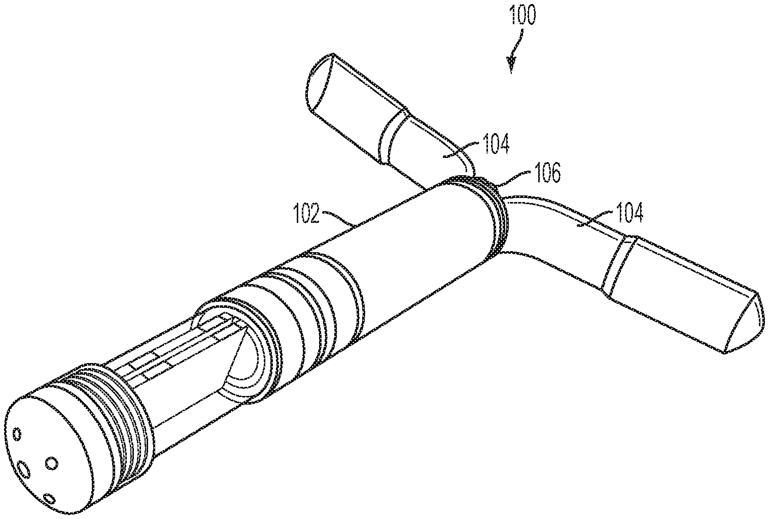
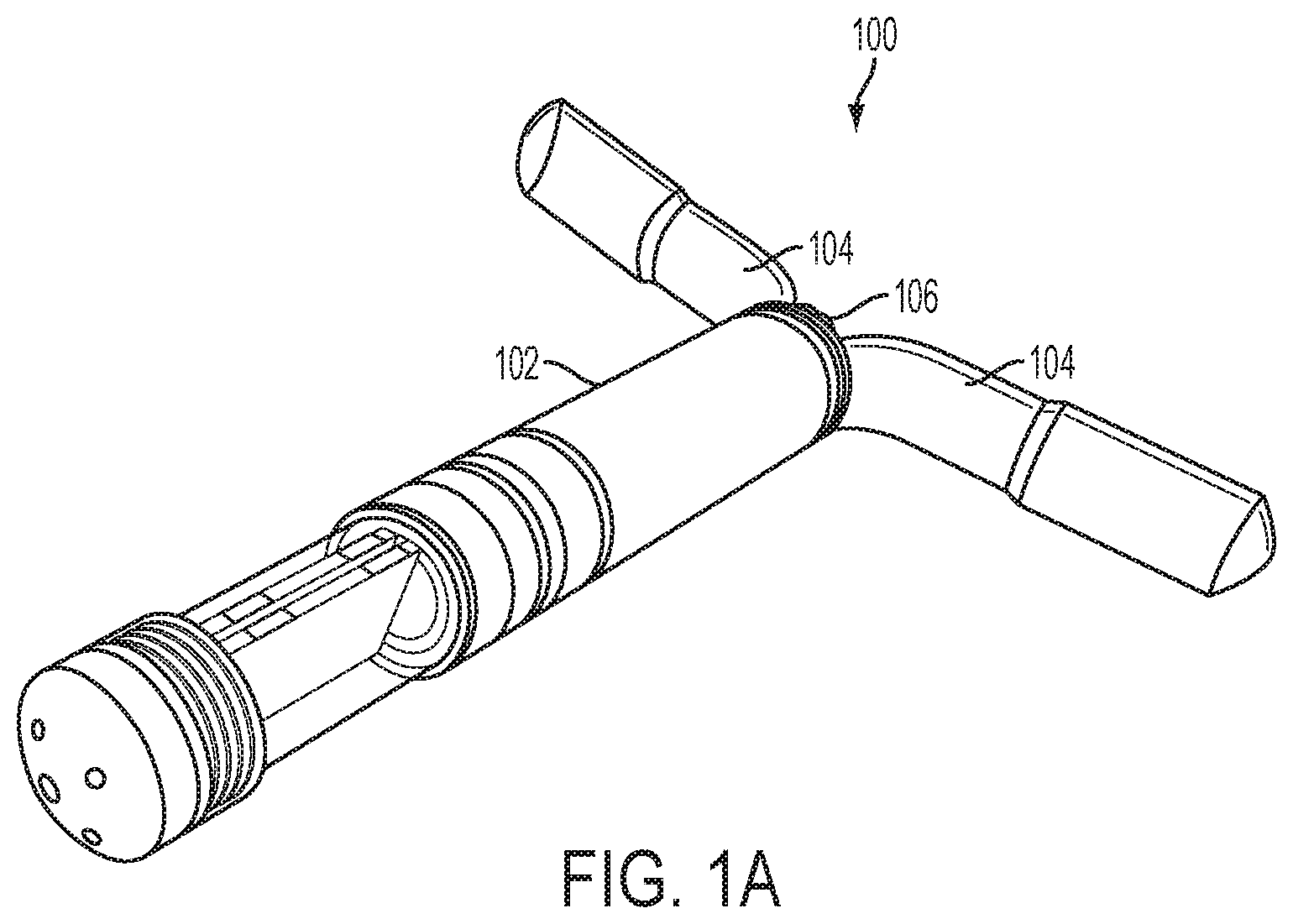
FIG. 1A is a perspective view of an implantable fluid delivery device.
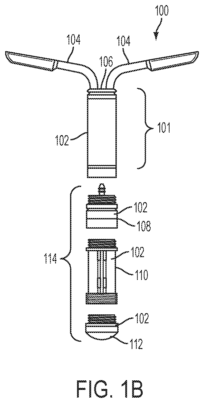
FIG. 1B is an exploded view of the implantable fluid delivery device of FIG. 1A.
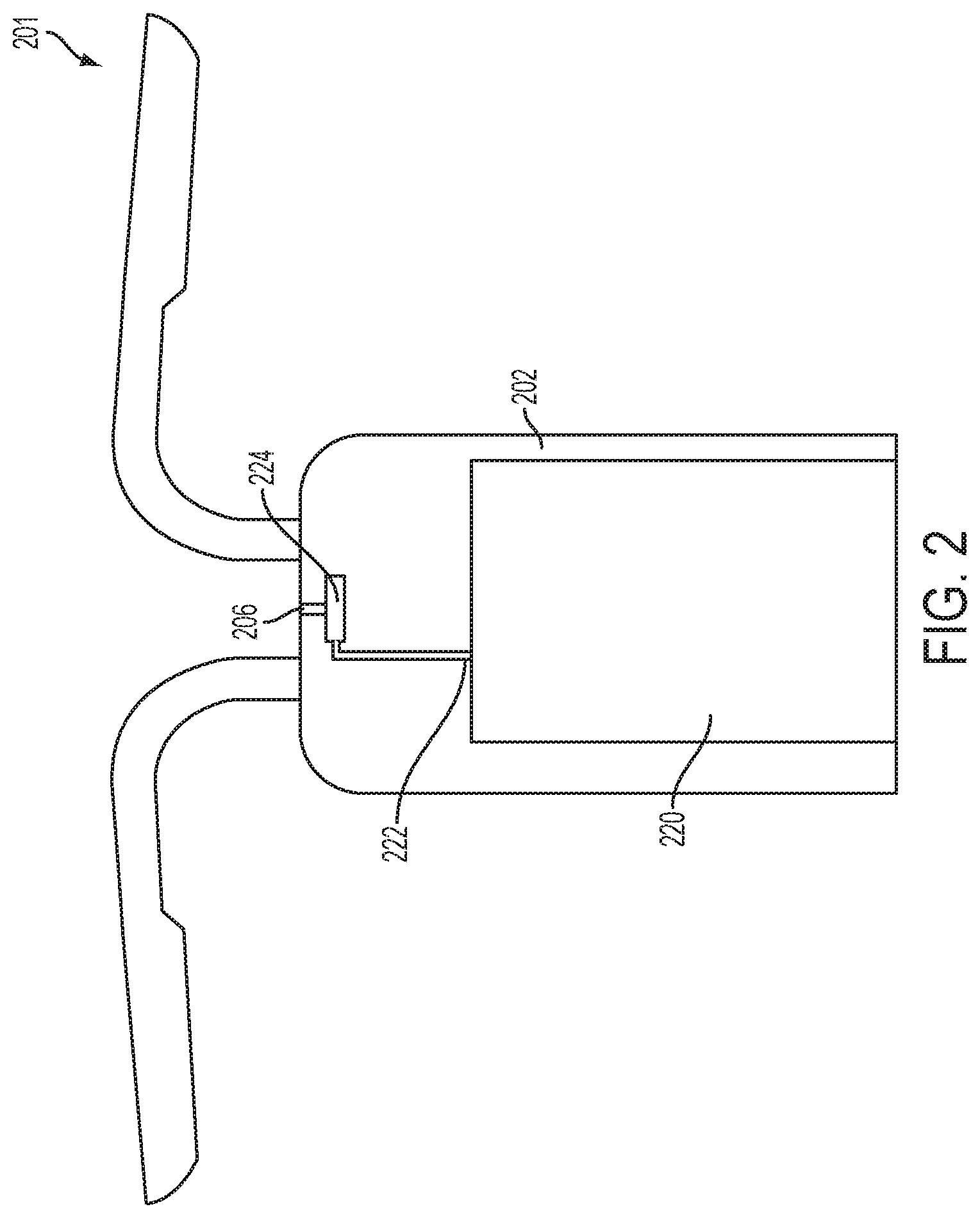
FIG. 2 is a partial cross-sectional view of one embodiment of an implantable fluid delivery device.
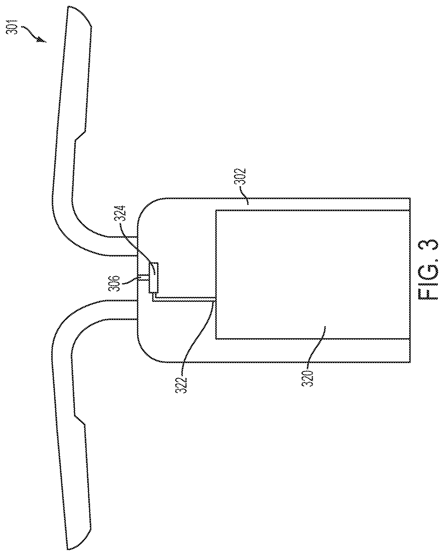
FIG. 3 is a partial cross-sectional view of another embodiment of an implantable fluid delivery device.
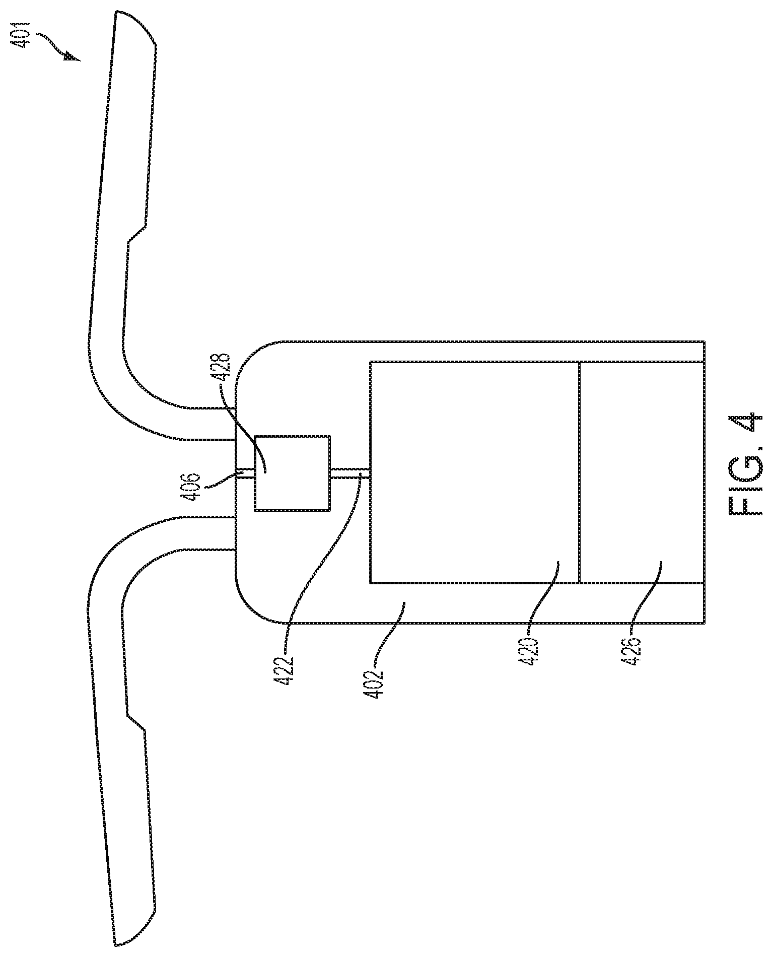
FIG. 4 is a partial cross-sectional view of yet another embodiment of an implantable fluid delivery device.
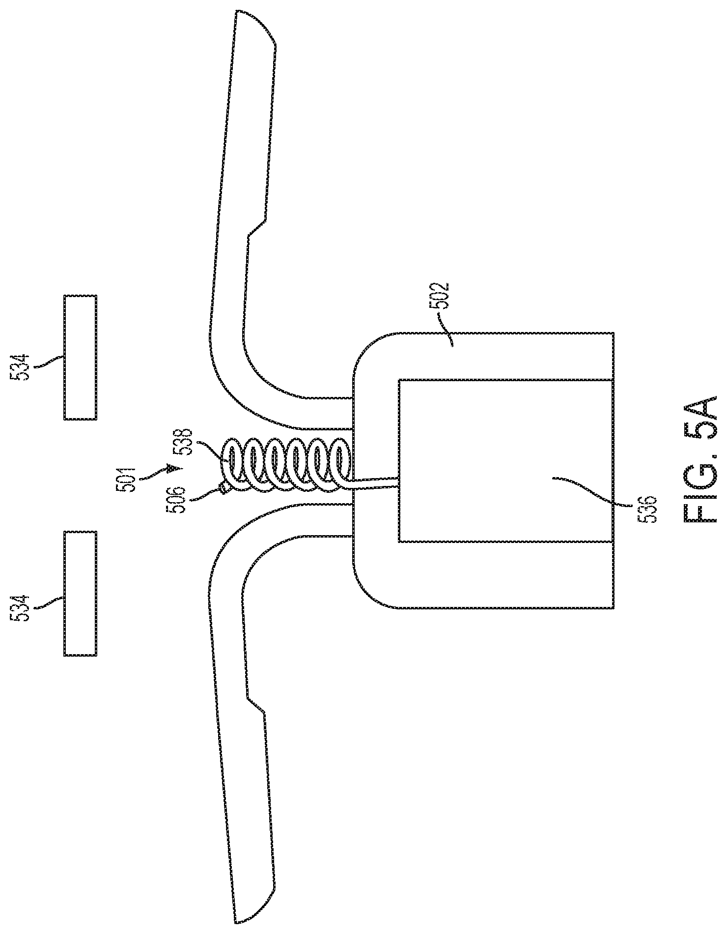
FIG. 5A is a partial cross-sectional view of yet another embodiment of an implantable fluid delivery device having an extending member, shown in the unstressed position.
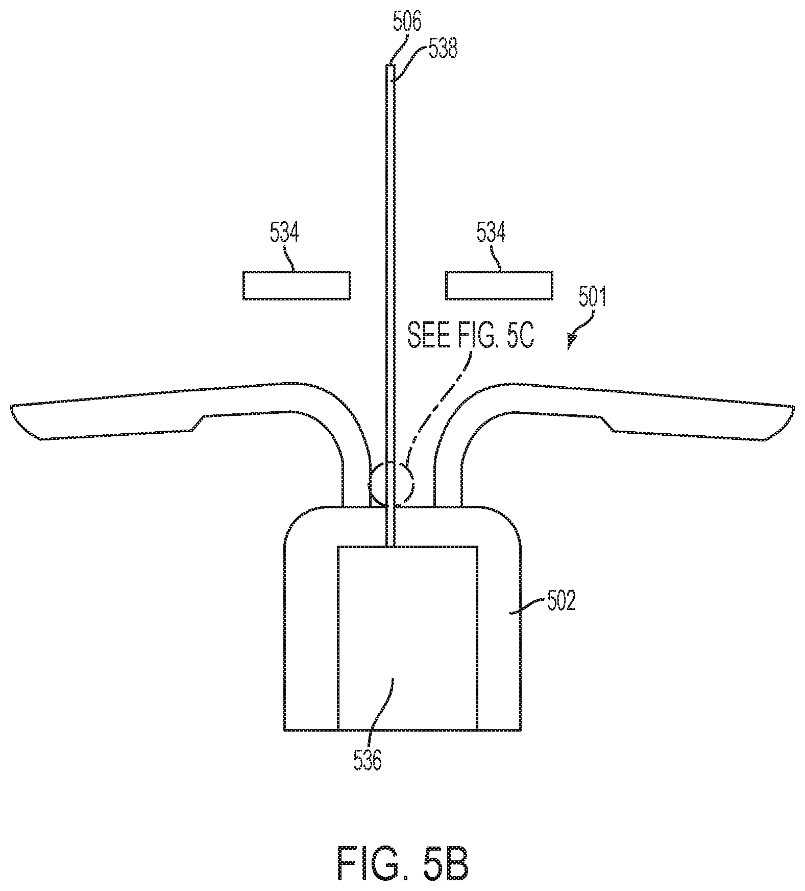
FIG. 5B is a partial cross-sectional view of the implantable fluid delivery device of FIG. 5A, showing the extending member in the extended position.
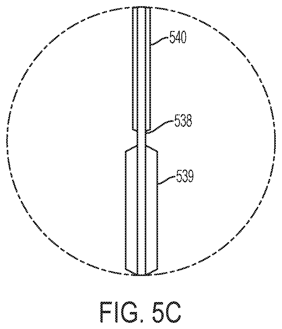
FIG. 5C is a magnified partial cross-sectional view of the implantable fluid delivery device of FIG. 5B.
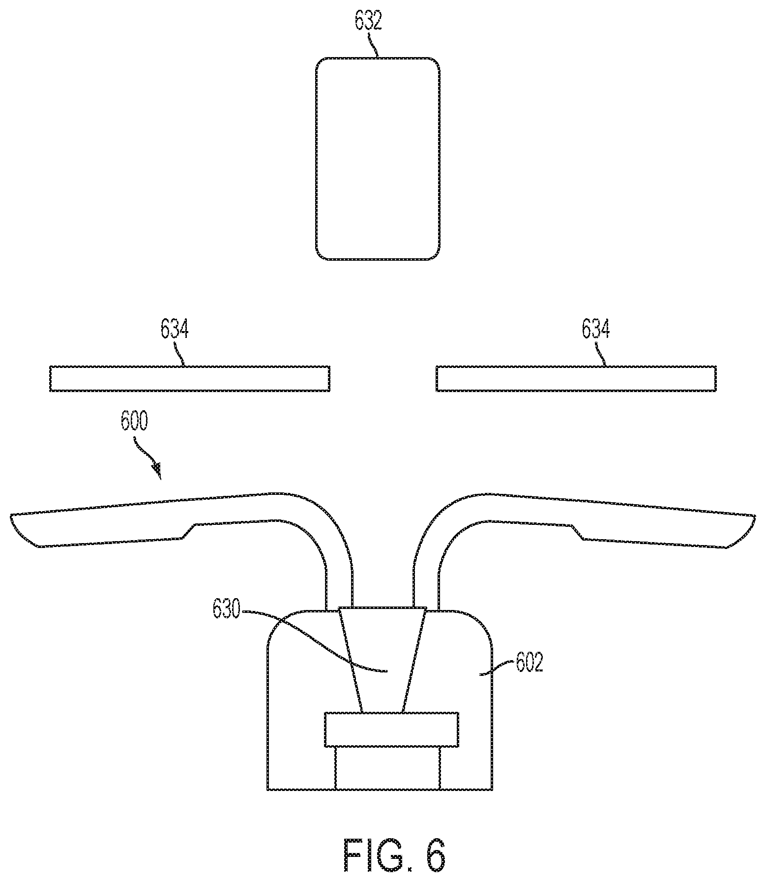
FIG. 6 is a partial cross-sectional view of one embodiment of an implantable fluid delivery system.
DETAILED DESCRIPTION
The devices, systems, and methods described herein meet one or more of the above-stated needed by provided implantable fluid delivery to the uterus of a subject. In certain embodiments, an intravaginal device is provided that is capable of delivering a fluid past the cervix and to the uterus of a subject.
Such devices may be particularly useful in animals, such as cattle, where the IVF procedure has to be performed by a skilled professional and is a time-consuming, costly, and intensive procedure for each animal. The devices, systems, and methods disclosed herein increase the likelihood of success of each IVF procedure by increasing the precision of the fluid delivery. As such, the valuable sperm and the time commitment from these professionals may be most effectively and efficiently used.
Implantable Fluid Delivery Devices and Systems
In one aspect, implantable fluid delivery devices and systems are provided, which allow for the controlled dispense or release of one or more fluids to the uterus of a subject. In embodiments, the release or dispense is temporally controlled, such that the fluid substance reaches the uterus at a selected time.
In one embodiment, as shown in FIGS. 1A and 1B, an implantable fluid delivery device 100 includes a housing 102 configured for intravaginal deployment and retention in a subject. For example, the housing 102 of the device 100 may be sized and shaped for intravaginal deployment and retention in the subject. In one embodiment, the device 100 includes one or more retention features 104, for retaining the device intravaginally upon deployment.
For example, as shown in FIGS. 1A and 1B, depending on the fluid dispensing mechanism, and the power and actuation needs of the device, the device 100 may include a control system 114 that includes one or more of a power source 112, a microcontroller 110, and an actuation mechanism 108. In addition, the device 100 may include a fluid dispensing system 101, which alone or in combination with the control system, operates to dispense or release a fluid to the subject. The device 100 may also include a fluid dispensing feature 106, such as a nozzle or opening, which is associated with the housing 102. For example, the nozzle or opening may have a small diameter, such that the device is capable of delivering a thin stream or small droplets of the fluid at a high velocity.
In certain embodiments, as shown in FIGS. 2, 3, 4, and 5A-5C, the fluid dispensing system 201, 301, 401, 501 of the device includes at least one reservoir 220, 320, 420, 538 associated with the housing 202, 302, 402, 502 and configured to contain a fluid, and a fluid dispensing mechanism disposed within the housing 202, 302, 402, 502 and configured to dispense the fluid from the at least one reservoir 220, 320, 420, 538 past the cervix (shown as 534 in FIGS. 5A-5C) and to the uterus of the subject. Various fluid dispensing mechanisms may be utilized in these devices, some of which are discussed herein. Other suitable fluid dispensing mechanisms known to those of ordinary skill in the art, or modified versions of the fluid dispensing mechanisms disclosed herein, may also be utilized.
In certain embodiments, the fluid dispensing mechanism is an inkjet or other high-velocity fluid dispensing mechanism. For example, a thermal bubble or piezoelectric-type inkjet dispensing mechanism may be utilized. These mechanisms may advantageously propel the fluid out of the device at a high velocity such that the fluid is likely to penetrate, or pass, the cervix of the subject.
In one embodiment, as shown in FIG. 2, the fluid dispensing mechanism is a thermal bubble jet mechanism, which includes a bubble jet chamber 224 in fluid communication with the at least one reservoir 220, and a nozzle 206 in fluid communication with the bubble jet chamber 224. For example, the bubble jet chamber 224 may be connected to the reservoir 220 by a channel 222 or other suitable connection means. In the embodiment shown in FIG. 2, the thermal bubble jet mechanism is configured to generate heat in the bubble jet chamber 224 and thereby create a bubble of the fluid such that a droplet of the fluid is dispensed via the nozzle 206 upon expansion of the bubble.
In one embodiment, the thermal bubble jet mechanism is configured to generate heat in the bubble jet chamber via one or more resistors. In one embodiment, the thermal bubble jet mechanism is configured to generate a vacuum in the bubble jet chamber 224 such that fluid in the at least one reservoir 220 is drawn into the bubble jet chamber 224 upon collapse of the bubble.
In one embodiment, as shown in FIG. 3, the fluid dispensing mechanism comprises a piezoelectric jet mechanism, which includes a jet chamber 324 in fluid communication with the at least one reservoir 320. For example, the jet chamber 324 may be connected to the reservoir 320 by a channel 322 or other suitable connection means. The fluid dispensing mechanism shown in FIG. 3 also includes a piezoelectric material in communication with the jet chamber 324 and a nozzle 306 in fluid communication with the jet chamber 324. The piezoelectric material is configured to receive an electric charge causing it to vibrate and thereby drive fluid in the jet chamber 324 therefrom such that the fluid is dispensed via the nozzle 306.
In one embodiment, the piezoelectric jet mechanism is configured to generate a vacuum in the jet chamber 324 such that fluid from the at least one reservoir 320 is drawn into the jet chamber 324 upon dispense of fluid via the nozzle 306.
In one embodiment, as shown in FIG. 4, the fluid dispensing mechanism includes a high velocity pump, which includes a valve 428 configured to selectively allow flow of the fluid from the at least one reservoir 420 to a nozzle 406 and a pressure source 426 configured to drive the fluid from the at least one reservoir 420 toward the nozzle 406. In one embodiment, the valve 428 is configured to allow flow of the fluid from the at least one reservoir 420 to the nozzle 406 upon generation of a sufficient pressure in the at least one reservoir 420 via the pressure source 426, such that the fluid is dispensed via the nozzle 406. As used herein, the term "sufficient pressure" refers to a pressure that is great enough to drive the fluid from the intravaginally deployed device, past the cervix to the uterus of the subject.
For example, the nozzle 406 may be connected to the reservoir 420 by a channel 422 or other suitable connection means, at which a valve may be located to regulate flow of the fluid to the nozzle. For example, the valve may be actuated by electronics on board the device, such as the controller of the control system.
In one embodiment, the pressure source includes compressed gases, springs, pistons, or combinations thereof. For example, the pressure source may include, or be associated with, an actuation mechanism 108 of a control system 114, as shown in FIG. 1B.
In one embodiment, as shown in FIGS. 5A-5C, the at least one reservoir includes a tube 538 extending from a gas reservoir 536 of the device, and which includes at least one gas chamber 539, 540 configured to receive gas from the gas reservoir 536 to inflate and thereby urge the tube 538 into an extended position (shown in FIG. 5B). In one embodiment, the at least one gas chamber 539, 540 of the tube 538 is in fluid communication with the fluid contained in the tube such that as the gas chamber 539, 540 inflates, the fluid is driven out of the tube 538.
For example, the tube may include an end nozzle 506 via which the fluid is dispensed from the tube 538. In certain embodiments, the fluid has a surface tension within the tube such that the fluid is not dispensed from the open end of the tube until a sufficient pressure from the inflation of the gas chamber(s) is applied thereto. Alternatively, the end of the tube may include a barrier structure, such as an end cap or seal, configured to maintain the fluid inside the tube until a sufficient pressure from the inflation of the gas chamber(s) ruptures, disengages, or otherwise removes, the barrier structure, such that the fluid can be dispensed.
In one embodiment, as shown in FIG. 5B, the tube 538 is sized to extend past the cervix 534 of the subject in the extended position. That is, the tube 538 may be designed to have a length that extends from the intended vaginal implantation site past the cervix of the subject in which the device is to be implanted. In one embodiment, as shown in FIGS. 5A and 5B, the tube 538 is configured to have a coiled unstressed position and the extended position is an uncoiled position. For example, each of the chambers may be inflated as gas is released from the gas reservoir and the chamber(s) expand thereby forcing the tubing to uncoil. The gas released from the gas reservoir may also serve to drive the fluid from the tube during or upon uncoiling of the tube.
For example, in devices having the extendable tube dispensing mechanism, the velocity of the fluid being dispensed may be lower than that of fluid being dispensed from a device without such an extension tube, because the fluid is being dispensed past the cervix.
In certain embodiments, the tube may be coated with an anti-microbial or anti-wetting coating to prevent contaminants from flowing into the tube from the vaginal or uterine deployment site, or from one gas chamber to another.
In one embodiment, the tube includes at least two gas chambers in series along the tube that have a seal therebetween, such that the second gas chamber may only begin to inflate upon full or near full inflation of the first gas chamber of the tube.
In certain embodiments, a dispense tube is combined with the inkjet-type or high-velocity dispense devices described above. That is, a tube extending between the device and the cervix or uterus of a subject may be provided, either independently of the device (e.g., the tube may be inserted into the subject prior to deployment of the device) or in association with the device (e.g., in connection with the dispensing nozzle or outlet of the device), to ensure delivery of the fluid to the desired site, such as the uterus. Incorporation of such a tube into the device or system may decrease the required fluid velocity produced by the dispensing mechanism, because the fluid is dispensed past the cervix via the tube. In certain embodiments, the tube may be coated with an anti-microbial or anti-wetting coating to prevent contaminants from flowing into the tube from the vaginal or uterine deployment site.
In one embodiment, as shown in FIG. 6, an implantable fluid delivery system includes a device 600 having a housing 602 configured for intravaginal deployment and retention in a subject and a fluid dispensing mechanism 630 disposed within the housing 602. The device may include any of the features, or combinations of features, described herein. The system also includes a capsule 632 containing a fluid to be delivered to the subject, the capsule 632 being configured to be inserted past the cervix 632 of the subject prior to deployment of the device 600. In one embodiment, the fluid dispensing mechanism 630 includes an ultrasonic element configured to generate an ultrasonic wave effective to rupture the capsule 632 and release the fluid to the uterus of the subject. For example, the capsule may be inserted past the cervix of the subject manually, for example by ranch personnel in the case of cattle, or using a deployment device configured to deploy the capsule past the cervix.
In one embodiment, the ultrasonic element comprises a piezoelectric material and an acoustic horn.
Suitable device features, including housing designs, retention features, retrieval members, control system features, and additional fluid dispensing mechanisms (not configured for uteral delivery from an intravaginal device), are disclosed in application Ser. No. 13/629,124, filed on Sep. 27, 2012, entitled "Single Channel, Multiple Drug Delivery Device and Methods", application Ser. No. 13/629,159, filed on Sep. 27, 2012, entitled "Multiple Reservoir Drug Delivery Device and Methods", application Ser. No. 13/629,184, filed on Sep. 27, 2012, entitled "Drug Reconstitution and Delivery Device and Methods", application Ser. No. 13/742,203, filed on Jan. 15, 2013, entitled "Devices and Methods for Intraluminal Retention and Drug Delivery", application Ser. No. 14/071,929, filed on Nov. 5, 2013, entitled "Fluid Delivery Devices and Methods", and application Ser. No. 14/107,367, filed on Dec. 16, 2013, entitled "Electrolytic Gas Generating Devices, Actuators, and Methods", each of which is incorporated herein by reference in its entirety.
Advantageously, the devices and systems described herein provide for fluid dispensing to a site past the cervix, with a vaginally implanted device, thereby increasing the precision of the fluid delivery and the likelihood of delivery to the uterus. Desirably, in IVF procedures, these devices and systems increase the efficiency and the likelihood of success of procedures, requiring less time and sperm per subject.
In certain embodiments, the devices described herein may be configured to dispense the fluid when an estrus condition of the subject detected by the device meets a predetermined threshold. That is, the device may be configured to detect when the subject is displaying ideal or near ideal insemination conditions (i.e., estrus) and to dispense the fluid in response to the detection of estrus. Devices for detecting estrus are described in more detail in co-pending application Ser. No. 14/448,074, filed on Jul. 31, 2014, entitled "Implantable Estrus Detection Devices, Systems, and Methods," which is incorporated herein by reference in its entirety.
In certain embodiments, the fluid includes drugs, semen, ova, or combinations thereof.
In certain embodiments, the fluid delivery devices disclosed herein may be configured to release two or more fluids therefrom, such as from separate reservoirs. For example, a device may be configured to dispense a series of drugs to the patient. For example, a device may be configured to dispense both an ova and semen to a patient.
Methods of Fluid Delivery
In another aspect, methods of delivering fluid to a subject are provided. For example, the methods may include deploying a fluid delivery device or system, such as those disclosed herein, in the subject. The devices and systems may include any features, or combinations of features, disclosed herein.
In one embodiment, a method of delivering fluid to a subject includes intravaginally deploying and retaining a device in the subject, and dispensing the fluid from the device such that the fluid is driven past the cervix to the uterus of the subject. For example, the device may include at least one reservoir containing a fluid and a fluid dispensing mechanism.
In one embodiment, dispensing the fluid from the device includes heating a portion of the fluid in a chamber to create a bubble such that a droplet of the fluid is dispensed via a nozzle upon expansion of the bubble.
In one embodiment, dispensing the fluid from the device includes providing an electric charge to a piezoelectric material, thereby causing it to vibrate and drive a portion of the fluid from a chamber such that the portion of fluid is dispensed from the device through a nozzle.
In one embodiment, dispensing the fluid from the device includes generating pressure in the at least one reservoir to drive the fluid toward a nozzle, and the device also includes a valve configured to allow flow of the fluid from the at least one reservoir to the nozzle upon generation of sufficient pressure in the at least one reservoir. For example, the pressure source may include compressed gases, a springs, pistons, and combinations thereof.
In one embodiment, the at least one reservoir includes a tube extending from a gas reservoir of the device, which includes at least one gas chamber that is in fluid communication with the fluid contained in the tube, and the step of dispensing the fluid from the device includes inflating the at least one gas chamber of the tube with gas from a gas reservoir of the device, thereby urging the tube into an extended position and driving the fluid from the tube. For example, the tube may be sized to extend past the cervix of the subject in the extended position. In one embodiment, the tube is configured to have a coiled unstressed position, and the extended position is an uncoiled position.
In certain embodiments, a method of delivering fluid to a subject includes inserting a capsule containing a fluid to be delivered to the subject past the cervix of the subject, thereafter intravaginally deploying a device in the subject, the device comprising a fluid dispensing mechanism, which comprises an ultrasonic element, and generating an ultrasonic wave, via the ultrasonic element, effective to rupture the capsule and release the fluid to the uterus of the subject. In one embodiment, the ultrasonic element includes a piezoelectric material and an acoustic horn.
In one embodiment, dispensing the fluid from the device such that the fluid is driven past the cervix to the uterus of the subject occurs after an estrus condition of the subject detected by the device meets a predetermined threshold. For example, the fluid may include drugs, semen, ova, and combinations thereof. In a particular embodiment, the subject is a horse, cow, sheep, or sow. In another embodiment, the subject is a woman.
It will be appreciated that variants of the above-disclosed and other features and functions, or alternatives thereof, may be combined into many other different devices, systems, methods, or applications. Various presently unforeseen or unanticipated alternatives, modifications, variations, or improvements therein may be subsequently made by those skilled in the art which are also intended to be encompassed by the following claims
* * * * *
References
D00000
D00001
D00002
D00003
D00004
D00005
D00006
D00007
D00008
D00009
XML
uspto.report is an independent third-party trademark research tool that is not affiliated, endorsed, or sponsored by the United States Patent and Trademark Office (USPTO) or any other governmental organization. The information provided by uspto.report is based on publicly available data at the time of writing and is intended for informational purposes only.
While we strive to provide accurate and up-to-date information, we do not guarantee the accuracy, completeness, reliability, or suitability of the information displayed on this site. The use of this site is at your own risk. Any reliance you place on such information is therefore strictly at your own risk.
All official trademark data, including owner information, should be verified by visiting the official USPTO website at www.uspto.gov. This site is not intended to replace professional legal advice and should not be used as a substitute for consulting with a legal professional who is knowledgeable about trademark law.