Helical balloon assist device and method for using the same
Lorenzo , et al. February 16, 2
U.S. patent number 10,918,390 [Application Number 15/941,166] was granted by the patent office on 2021-02-16 for helical balloon assist device and method for using the same. This patent grant is currently assigned to DePuy Synthes Products, Inc.. The grantee listed for this patent is DePuy Synthes Products, Inc.. Invention is credited to Kirk Johnson, Juan Lorenzo.


| United States Patent | 10,918,390 |
| Lorenzo , et al. | February 16, 2021 |
Helical balloon assist device and method for using the same
Abstract
The helical balloon assist device includes a tubular balloon formed at least partially into an independent helical shape in an uninflated state and an inflation tube in sealed communication with the balloon and extending from the helical balloon assist device in a proximal direction. The helical balloon assist device may include an inner core member formed at least partially into an independent helical shape and supporting the helical shape of the tubular balloon.
| Inventors: | Lorenzo; Juan (Raynham, MA), Johnson; Kirk (Raynham, MA) | ||||||||||
|---|---|---|---|---|---|---|---|---|---|---|---|
| Applicant: |
|
||||||||||
| Assignee: | DePuy Synthes Products, Inc.
(Raynham, MA) |
||||||||||
| Family ID: | 1000005362897 | ||||||||||
| Appl. No.: | 15/941,166 | ||||||||||
| Filed: | March 30, 2018 |
Prior Publication Data
| Document Identifier | Publication Date | |
|---|---|---|
| US 20190298384 A1 | Oct 3, 2019 | |
| Current U.S. Class: | 1/1 |
| Current CPC Class: | A61B 17/12109 (20130101); A61M 25/1002 (20130101); A61B 17/1204 (20130101); A61B 17/12136 (20130101); A61B 17/12036 (20130101); A61M 25/0662 (20130101); A61B 2017/00862 (20130101); A61B 2017/1205 (20130101); A61M 2025/0681 (20130101) |
| Current International Class: | A61B 17/12 (20060101); A61M 25/06 (20060101); A61M 25/10 (20130101); A61B 17/00 (20060101) |
References Cited [Referenced By]
U.S. Patent Documents
| 3811448 | May 1974 | Morton |
| 4762130 | August 1988 | Fogarty |
| 5181911 | January 1993 | Shturman |
| 5226888 | July 1993 | Arney |
| 5295958 | March 1994 | Shturman |
| 5554119 | September 1996 | Harrison |
| 5772681 | June 1998 | Leoni |
| 5797948 | August 1998 | Dunham |
| 5855546 | January 1999 | Hastings |
| 6196996 | March 2001 | Teirstein |
| 6391037 | May 2002 | Greenhalgh |
| 6398708 | June 2002 | Hastings et al. |
| 6409652 | June 2002 | Kamdar |
| 7081115 | July 2006 | Taimisto |
| 7766871 | August 2010 | Hirszowicz |
| 8079978 | December 2011 | Hirszowicz et al. |
| 9149288 | October 2015 | Teague |
| 9232992 | January 2016 | Heidner |
| 9532792 | January 2017 | Galdonik et al. |
| 9532873 | January 2017 | Kelley |
| 9533344 | January 2017 | Monetti et al. |
| 9539011 | January 2017 | Chen et al. |
| 9539022 | January 2017 | Bowman |
| 9539122 | January 2017 | Burke et al. |
| 9539382 | January 2017 | Nelson |
| 9549830 | January 2017 | Bruszewski et al. |
| 9554805 | January 2017 | Tompkins et al. |
| 9561125 | February 2017 | Bowman et al. |
| 9572982 | February 2017 | Burnes et al. |
| 9579484 | February 2017 | Barnell |
| 9585642 | March 2017 | Dinsmoor et al. |
| 9615832 | April 2017 | Bose et al. |
| 9615951 | April 2017 | Bennett et al. |
| 9622753 | April 2017 | Cox |
| 9636115 | May 2017 | Henry et al. |
| 9636439 | May 2017 | Chu et al. |
| 9642675 | May 2017 | Werneth et al. |
| 9655633 | May 2017 | Leynov et al. |
| 9655645 | May 2017 | Staunton |
| 9655989 | May 2017 | Cruise et al. |
| 9662129 | May 2017 | Galdonik et al. |
| 9662238 | May 2017 | Dwork et al. |
| 9662425 | May 2017 | Lilja et al. |
| 9668898 | June 2017 | Wong |
| 9675477 | June 2017 | Thompson |
| 9675782 | June 2017 | Connolly |
| 9676022 | June 2017 | Ensign |
| 9692557 | June 2017 | Murphy |
| 9693852 | July 2017 | Lam et al. |
| 9700262 | July 2017 | Janik et al. |
| 9700399 | July 2017 | Acosta-Acevedo |
| 9717421 | August 2017 | Griswold et al. |
| 9717500 | August 2017 | Tieu et al. |
| 9717502 | August 2017 | Teoh et al. |
| 9724103 | August 2017 | Cruise et al. |
| 9724526 | August 2017 | Strother et al. |
| 9750565 | September 2017 | Bloom et al. |
| 9757260 | September 2017 | Greenan |
| 9764111 | September 2017 | Gulachenski |
| 9770251 | September 2017 | Bowman |
| 9770577 | September 2017 | Li |
| 9775621 | October 2017 | Tompkins et al. |
| 9775706 | October 2017 | Peterson |
| 9775732 | October 2017 | Khenansho |
| 9788800 | October 2017 | Mayoras, Jr. |
| 9795391 | October 2017 | Saatchi et al. |
| 9801980 | October 2017 | Karino et al. |
| 9808599 | November 2017 | Bowman |
| 9833252 | December 2017 | Sepetka |
| 9833604 | December 2017 | Lam |
| 9833625 | December 2017 | Waldhauser et al. |
| 10286184 | May 2019 | Laduca |
| 2002/0045925 | April 2002 | Keller |
| 2005/0197667 | September 2005 | Chan |
| 2006/0064151 | March 2006 | Guterman |
| 2006/0287666 | December 2006 | Saadat |
| 2008/0281350 | November 2008 | Sepetka |
| 2009/0209969 | August 2009 | Wolfe |
| 2010/0145265 | June 2010 | Min |
| 2010/0324649 | December 2010 | Mattsson |
| 2011/0144742 | June 2011 | Madrid |
| 2012/0226303 | September 2012 | Roche |
| 2012/0245520 | September 2012 | Kelly |
| 2012/0283768 | November 2012 | Cox et al. |
| 2014/0135812 | May 2014 | Divino et al. |
| 2014/0135891 | May 2014 | Poehlmann |
| 2014/0200607 | July 2014 | Sepetka et al. |
| 2014/0249506 | September 2014 | Laduca |
| 2015/0238729 | August 2015 | Jenson |
| 2017/0007264 | January 2017 | Cruise et al. |
| 2017/0007265 | January 2017 | Guo et al. |
| 2017/0020670 | January 2017 | Murray et al. |
| 2017/0020700 | January 2017 | Bienvenu |
| 2017/0027640 | February 2017 | Kunis et al. |
| 2017/0027692 | February 2017 | Bonhoeffer |
| 2017/0027725 | February 2017 | Argentine |
| 2017/0035436 | February 2017 | Morita |
| 2017/0035567 | February 2017 | Duffy |
| 2017/0042548 | February 2017 | Lam |
| 2017/0049596 | February 2017 | Schabert |
| 2017/0071737 | March 2017 | Kelley |
| 2017/0072452 | March 2017 | Monetti et al. |
| 2017/0079671 | March 2017 | Morero et al. |
| 2017/0079680 | March 2017 | Bowman |
| 2017/0079766 | March 2017 | Wang |
| 2017/0079767 | March 2017 | Leon-Yip |
| 2017/0079812 | March 2017 | Lam et al. |
| 2017/0079817 | March 2017 | Sepetka |
| 2017/0079819 | March 2017 | Pung et al. |
| 2017/0079820 | March 2017 | Lam et al. |
| 2017/0086851 | March 2017 | Wallace |
| 2017/0086996 | March 2017 | Peterson et al. |
| 2017/0095259 | April 2017 | Tompkins et al. |
| 2017/0100126 | April 2017 | Bowman et al. |
| 2017/0100141 | April 2017 | Morero et al. |
| 2017/0100143 | April 2017 | Grandfield |
| 2017/0100183 | April 2017 | Iaizzo |
| 2017/0113023 | April 2017 | Steingisser et al. |
| 2017/0147765 | May 2017 | Mehta |
| 2017/0151032 | June 2017 | Loisel |
| 2017/0165062 | June 2017 | Rothstein |
| 2017/0165065 | June 2017 | Rothstein |
| 2017/0165454 | June 2017 | Tuohy |
| 2017/0172581 | June 2017 | Bose et al. |
| 2017/0172766 | June 2017 | Vong et al. |
| 2017/0172772 | June 2017 | Khenansho |
| 2017/0189033 | July 2017 | Sepetka et al. |
| 2017/0189035 | July 2017 | Porter |
| 2017/0215902 | August 2017 | Leynov et al. |
| 2017/0216484 | August 2017 | Cruise et al. |
| 2017/0224350 | August 2017 | Shimizu et al. |
| 2017/0224355 | August 2017 | Bowman et al. |
| 2017/0224467 | August 2017 | Piccagli et al. |
| 2017/0224511 | August 2017 | Dwork et al. |
| 2017/0224953 | August 2017 | Tran et al. |
| 2017/0231749 | August 2017 | Perkins et al. |
| 2017/0252064 | September 2017 | Staunton |
| 2017/0265983 | September 2017 | Lam et al. |
| 2017/0281192 | October 2017 | Tieu et al. |
| 2017/0281331 | October 2017 | Perkins et al. |
| 2017/0281344 | October 2017 | Costello |
| 2017/0281909 | October 2017 | Northrop et al. |
| 2017/0281912 | October 2017 | Melder |
| 2017/0290593 | October 2017 | Cruise et al. |
| 2017/0290654 | October 2017 | Sethna |
| 2017/0296324 | October 2017 | Argentine |
| 2017/0296325 | October 2017 | Marrocco et al. |
| 2017/0303939 | October 2017 | Greenhalgh |
| 2017/0303942 | October 2017 | Greenhalgh et al. |
| 2017/0303947 | October 2017 | Greenhalgh |
| 2017/0303948 | October 2017 | Wallace et al. |
| 2017/0304041 | October 2017 | Argentine |
| 2017/0304097 | October 2017 | Corwin et al. |
| 2017/0304595 | October 2017 | Nagasrinivasa |
| 2017/0312109 | November 2017 | Le |
| 2017/0312484 | November 2017 | Shipley et al. |
| 2017/0316561 | November 2017 | Helm et al. |
| 2017/0319826 | November 2017 | Bowman |
| 2017/0333228 | November 2017 | Orth et al. |
| 2017/0333236 | November 2017 | Greenan |
| 2017/0333678 | November 2017 | Bowman |
| 2017/0340383 | November 2017 | Bloom et al. |
| 2017/0348014 | December 2017 | Wallace |
| 2017/0348514 | December 2017 | Guyon et al. |
| 2018/0014829 | January 2018 | Tal |
| 0 275 230 | Jul 1988 | EP | |||
| 2017/081561 | May 2017 | WO | |||
Other References
|
European Search Report issued in corresponding European Patent Application No. 19 16 6286 dated Aug. 27, 2019. cited by applicant. |
Primary Examiner: Ho; Tan-Uyen T
Assistant Examiner: Wei; Charles M
Attorney, Agent or Firm: Troutman Pepper Hamilton Sanders LLP
Claims
The invention claimed is:
1. A helical balloon assisted catheter system comprising: a catheter; and a helical balloon assist device, slidably contacting an outside of the catheter, the helical balloon assist device comprising: a tubular balloon formed at least partially into an independent helical shape in an uninflated state, a distalmost end of the tubular balloon slidably contacting the outside of the catheter, the helical shape comprises a plurality of turns defining an inner diameter of the helical shape, the inner diameter being consistent along at least a majority of the length of the helical shape, and at least a portion of the turns are movable to resize a gap between adjacent turns in the plurality of turns; and an inflation tube in sealed communication with the balloon and extending from a proximal end of the balloon in a proximal direction along the outside of the catheter.
2. The helical balloon assisted catheter system of claim 1, wherein the helical balloon assist device further comprises an inner core member formed at least partially into an independent helical shape and supporting the helical shape of the tubular balloon.
3. The helical balloon assisted catheter system of claim 2 where the inner core member is formed of a resilient material.
4. The helical balloon assisted catheter system of claim 2 where the inner core member is secured to the balloon.
5. The helical balloon assisted catheter system of claim 4 where the inner core member is secured to an interior portion of a balloon wall closest to a helical axis.
6. The helical balloon assisted catheter system of claim 4 where the inner core member is secured to an interior portion of a balloon wall farthest to a helical axis.
7. The helical balloon assisted catheter system of claim 4 where the inner core member is secured to a balloon wall by an adhesive, by welding, or by mechanical fastening.
8. The helical balloon assisted catheter system of claim 2 where the inner core member is formed in a multiple helix shape comprising a second helix extending helically along a wall of the tubular balloon.
9. The helical balloon assisted catheter system of claim 2 where the inner core member is not secured to the balloon.
10. The helical balloon assisted catheter system of claim 1 where the balloon comprises an elastic material.
11. The helical balloon assisted catheter system of claim 1 where the balloon comprises an inelastic material.
12. The helical balloon assisted catheter system of claim 1 further comprising a positioner fabricated from a resilient material.
13. The helical balloon assisted catheter system of claim 12 where the positioner comprises the inflation tube.
14. The helical balloon assisted catheter system of claim 12 where the positioner is configured to position the balloon in a distal direction and a proximal direction.
15. A helical balloon assisted catheter system comprising: a catheter; and a helical balloon assist device, slidably contacting an outside of the catheter, comprising: a tubular balloon formed at least partially into an independent helical shape in an uninflated state, a distalmost end of the tubular balloon slidably contacting the outside of the catheter, and an inflation tube in sealed communication with the balloon and extending from the balloon in a proximal direction along the outside of the catheter.
16. The balloon assisted catheter system of claim 15 further comprising a positioner pushable to move the balloon in a distal direction and pullable to move the balloon in a proximal direction along the catheter.
17. The balloon assisted catheter system of claim 15 further comprising an inner core member formed at least partially into an independent helical shape and supporting the helical shape of the tubular balloon.
Description
FIELD
This disclosure relates generally to the field of tools for vascular surgery. More particularly, it relates to balloon devices for occluding blood vessels during vascular surgery.
BACKGROUND
Balloon Guide Catheters facilitate the insertion of intravascular devices as well as control/restrict flow in ischemic applications. They are designed to have a large lumen to maximize clot capture, and are indicated for use as a conduit for clot retrieval devices. Because the balloon is an integral part of the assembly on these devices, the profile of the devices is very large, for example 8 F (2.7 mm) (French "F"=0.33 mm) as compared to a regular large ID guide catheter which might be sized 6 F (2.0 mm). Also, the overall flexibility of the system is decreased due to the required inflation lumen and dual layer construction needed to inflate the distal balloon. The combination of the large overall profile and the lack of distal flexibility makes tracking these devices in the neurovascular anatomy difficult. Accordingly, use of these devices is mostly limited to the proximal cerebral vasculature.
SUMMARY
To address these deficiencies in the existing art, a helical balloon assist device can include a tubular balloon formed at least partially into an independent helical shape in an uninflated state and an inflation tube in sealed communication with the balloon and extending from the helical balloon assist device in a proximal direction. The helical balloon assist device can also have an inner core member formed at least partially into an independent helical shape and supporting the helical shape of the tubular balloon. In examples, the inner core member may be formed of a resilient material.
Other examples have the inner core member secured to the balloon or secured to an interior portion of a balloon wall closest or farthest to a helical axis. The inner core member can be secured to a balloon wall by an adhesive, by welding, or by mechanical fastening. Other examples have the inner core member not secured to the balloon. The inner core member can be formed in a multiple helix shape with a second helix extending helically along a wall of the tubular balloon. Examples of the balloon include it being made of an elastic material or an inelastic material.
The helical balloon assist device can also have a positioner fabricated from a resilient material, and in certain examples, the positioner is the inflation tube. The positioner can be configured to position the helical balloon assist device in a radial direction.
The helical balloon assist device can be paired with a catheter system having a catheter and the helical balloon assist device, slidably engaging an outside of the catheter.
An exemplary method of using a helical balloon assist device can include the steps of deforming a distal turn of a balloon of the helical balloon assist device to create or expand a gap between turns of the balloon of the helical balloon assist device. Then inserting a catheter through the gap between the turns of the balloon, twisting the helical balloon assist device to fully mount the helical balloon assist device onto the catheter, and sliding the helical balloon assist device along the catheter, using an inflation tube or a positioner, to a treatment site in a patient's vasculature. The method can further include the steps of inflating the balloon of the helical balloon assist device using the inflation tube and then performing a clinical procedure. Afterwards, deflating the balloon of the helical balloon assist device using the inflation tube, and withdrawing the helical balloon assist device from the patient. In these examples, inflating the balloon of the helical balloon assist device causes at least a partial occlusion of a patient's blood vessel adjacent to the treatment site.
BRIEF DESCRIPTION OF THE DRAWINGS
FIG. 1 is a diagram of the helical balloon assist device illustrating its basic components, in accordance with the present disclosure.
FIG. 2 is a diagram of the balloon assembly of the helical balloon assist device illustrating the balloon in the deflated state, in accordance with the present disclosure.
FIG. 3 is a diagram of the balloon assembly of the helical balloon assist device illustrating the balloon in the inflated state, in accordance with the present disclosure.
FIG. 4A is a cross-sectional diagram of the balloon assembly of the helical balloon assist device, illustrating one example of the inner core member positioned within the balloon close to the outside diameter of a catheter, in accordance with the present disclosure.
FIG. 4B is a cross-sectional diagram of the balloon assembly of the helical balloon assist device, illustrating one example of the inner core member positioned within the balloon far from the outside diameter of a catheter, in accordance with the present disclosure
FIG. 4C is a cross-sectional diagram of the balloon assembly of the helical balloon assist device, illustrating one example of the inner core member positioned within the wall of the balloon, in accordance with the present disclosure
FIG. 4D is a cross-sectional diagram of the balloon assembly of the helical balloon assist device, illustrating one example of the inner core member positioned within the balloon, in a multiple-helix shape, in accordance with the present disclosure.
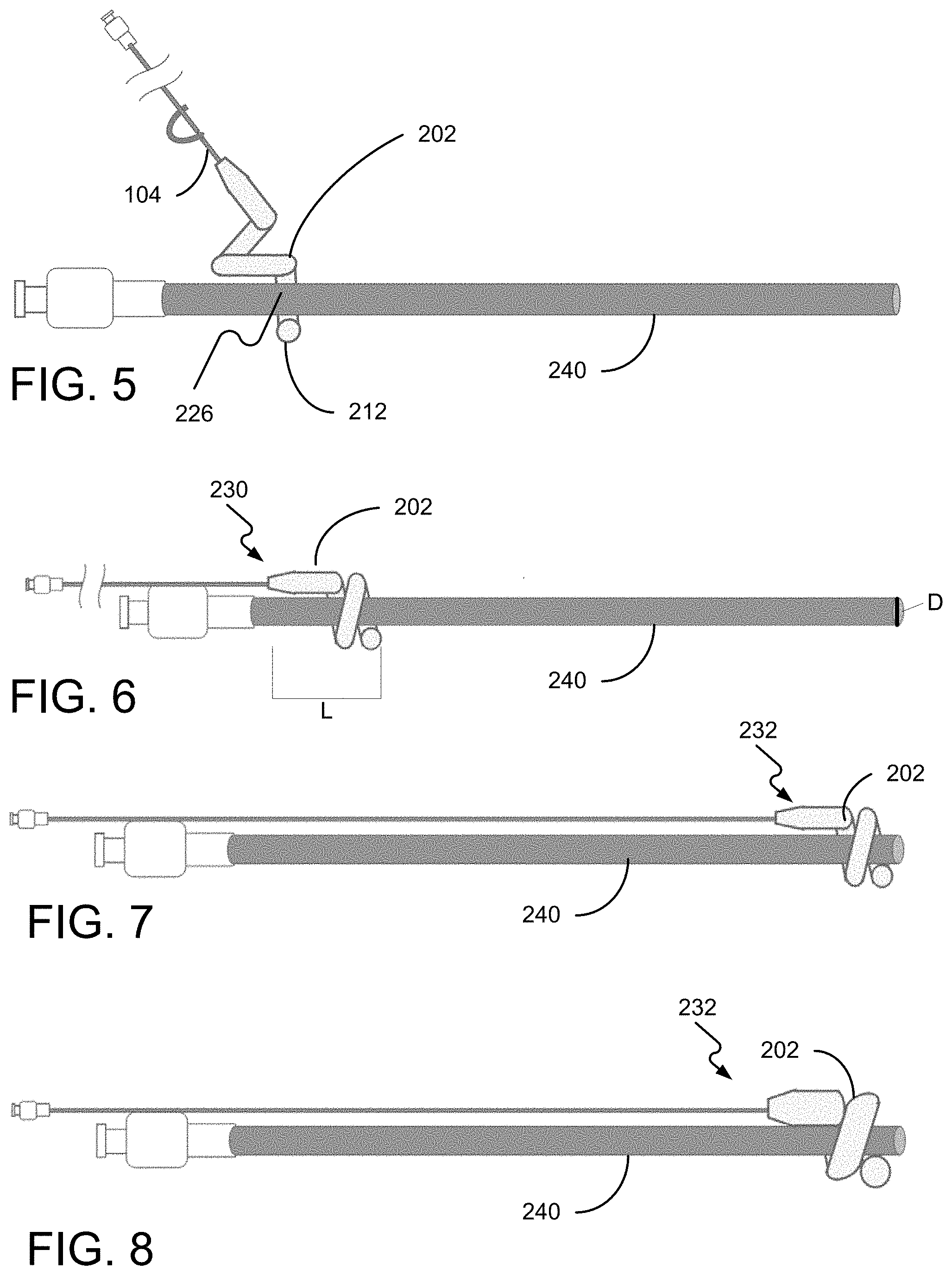
FIG. 5 is a diagram of mounting the helical balloon assist device on the proximal end of the catheter body, in accordance with the present disclosure.
FIG. 6 is a diagram of mounting the helical balloon assist device fully mounted on the proximal end of the catheter body, in accordance with the present disclosure.
FIG. 7 is a diagram of the helical balloon assist device mounted on the catheter body and positioned at the distal end of the catheter, in accordance with the present disclosure.
FIG. 8 is a diagram of the helical balloon assist device balloon inflated at the distal end of the catheter, in accordance with the present disclosure.
FIG. 9 is a diagram of a catheter positioned in a patient's vasculature with the helical balloon assist device mounted to the proximal end of the catheter body, in accordance with the present disclosure.
FIG. 10 is a diagram of a catheter positioned in a patient's vasculature with the helical balloon assist device positioned on the distal end of the catheter body at the treatment site, in accordance with the present disclosure.
FIG. 11 is a diagram of a catheter positioned in a patient's vasculature with the balloon inflated at the treatment site, occluding a blood vessel, in accordance with the present disclosure.
FIG. 12 is a flow chart illustrating one example of a method for using the helical balloon assist device, in accordance with the present disclosure.
DETAILED DESCRIPTION
Referring now to the Figures, in which like reference numerals represent like parts, various examples of the helical balloon assist device and methods of using it will be disclosed in detail. FIG. 1 is a diagram of the helical balloon assist device illustrating is basic components. The helical balloon assist device 100 includes a balloon assembly 200, an inflation tube 104, and an inflation port 106. FIG. 2 is a closer view of the balloon assembly 200. The balloon assembly includes the balloon 202 supported by an inner core member 204. The balloon 202 can be formed from an elastic or semi-elastic material, like polyimide. The balloon 202 extends helically along and about an axis 208 from a proximal end 210 to a distal end 212. The inner core member 204 is a helical element supporting the balloon 202. In one example, the inner core member 204 may be a wire. Although a particular shape of the balloon 202 is illustrated, the disclosure is not limited to the shape shown.
The balloon 202 may have a straight section 214 at one or both ends which extends parallel to the axis 208. The straight section 214 may improve the robustness of the bond to the inflation tube 104, may improve the grip of the balloon 202 on a catheter 240, or may improve the ease of tracking the balloon 202 along the catheter 240. Alternatively, the balloon 202 may be purely helical. The helical portion 250 of the balloon 202 is described by a tube diameter 252, a nominal diameter 254 which defines the distance between the turns of the balloon 202 and the axis 208, and pitch 256 between turns of the balloon 202. The tube diameter 252 may be constant or variable. In some examples, the tube diameter 252 may taper toward the end 212 of the balloon 202. The pitch 256 may be constant or may be variable. In one example (not shown), the balloon 202 may have a "closed" end where a partial turn is non-helical, but instead has zero pitch and coils around the catheter following a plane perpendicular to the axis 208, similar to the "closed" end of a helical compression spring.
The balloon 202 is inflated using the inflation tube 104. Sterile water, saline, or another appropriate solution may be introduced to the inflation tube 104 at the inflation port 106. The inflation port 106 may be one of several types known in the industry. The inflation tube 104 has an open end 218 which terminates inside the balloon 202. The outer perimeter of the inflation tube 104 is bonded to balloon 202 at a location proximal to its open end 218. The bond provides a hermetic seal and a robust mechanical attachment to withstand forces during use of the helical balloon assist device 100.
The inflation tube 104 may be made from metal to facilitate pushability of the balloon 202 along the catheter 240, a polymeric material such as a polyimide for flexibility, or a combination of metal at the proximal end 210 and transitioning to the polymeric material as it extends toward the distal end 212. In some examples the inflation tube 104 may be used to position the helical balloon assist device 100 along the catheter 240 in the distal direction and to retract it in the proximal direction. In some examples, the inflation tube 104 may be attached to the inner core member 204. In other examples a separate positioner (not shown) may be attached to the balloon 202 and/or the inner core member 204 to advance the helical balloon assist device 100 along the catheter 240 in the distal direction and to retract it in the proximal direction, allowing the inflation tube 104 to be more flexible. The positioner may be made of a resilient material such as spring-temper stainless steel or, more preferably, Nitinol. In several examples the positioner may be attached by welding, for example by laser or ultrasonic means, by adhesive, by crimping, or by thermal staking, as may be appropriate depending on the materials of the positioner, the inner body 104, and/or the balloon 202.
A length L of the balloon assembly 200 may be relatively short in the axial direction. In one example, the balloon assembly 200 may be less than or equal to twice the outside diameter D of the catheter 240 (see, FIG. 6). In another example, the balloon assembly 200 may be less than or equal to the outside diameter D catheter 240. The short length L allows the balloon assembly 200 to track over tighter-radius bends of the catheter 240 which guides it.
FIGS. 4A-4D illustrate examples of the inner core member 204. In one example, the inner core member 204 is made of a resilient material such as spring-temper stainless steel or, more preferably, a superelastic material such as Nitinol. The inner core member 204 has a helical shape which supports the balloon 202. The inner core member 204 may be secured to the balloon 202 or may be loose within the balloon 202. The inner core member 204 may be secured by an adhesive, by ultrasonic welding, by mechanical fasteners, by heat staking, or by other means known to those skilled in the art. If secured to the balloon 202, the inner core member 204 may be secured to the interior 216 of the balloon 202, the exterior of the balloon 202, or within a wall 220 of the balloon 202, as shown in FIG. 4C. The inner core member 204 may also be secured to the inflation tube 104 by an adhesive, by ultrasonic welding, by mechanical fasteners, by heat staking, or by other means known to those skilled in the art. In one example, the inner core member 204 may be formed into a helix following the wall 220 of the balloon 202 closest to the catheter 240, i.e., a helix having a nominal diameter similar to the outer diameter 242 of the catheter 240 as shown in FIG. 4A. In another example, the inner core member 204 may be formed into a helix following the wall 220 of the balloon 202 farthest to the catheter 240 as shown in FIG. 4B, i.e., a helix having a nominal diameter approximately equal to the outer diameter D (illustrated by a circumference 242) of the catheter 240 plus twice the tube diameter of the balloon 202.
In another example, the inner core member 204 may be formed into a multiple helix 222 which helically follows the inside wall 220 of the helical shape of the balloon 202 as shown in FIG. 4D. The multiple helix 222 has a nominal diameter approximately equal to the tube diameter of the balloon and winds helically along an axis approximating a spline following the center of the balloon tube. Thus, the multiple helix 222 resembles a long coil spring wrapped around the catheter 240. The multiple helix 222 may be formed, for example, mechanically or by heat-treating the inner core member 204 on a form.
FIGS. 5-8 show the basic operation of the helical balloon assist device 100. FIG. 5 shows the balloon assist device being temporarily deformed and mounted on the catheter by twisting in a corkscrew fashion. The distal end 212 of the balloon 202 is deformed to create a gap 226 between the distal-most turn of the balloon 202 and the next-most distal turn. FIG. 6 shows the helical balloon assist device fully mounted on the catheter in a proximal position 230. The helical balloon assist device 100 is then slid along the catheter 240 using the inflation tube 104 or a separate positioner (not shown). FIG. 7 shows the helical balloon assist device 100 mounted on the catheter 240 in the distal position 232 after sliding along the catheter 240. The balloon 202 is then inflated using the inflation tube 104, as shown in FIG. 8.
FIGS. 9-11 show the basic operation of the helical balloon assist device 100 during a medical procedure. FIG. 9 shows the helical balloon assist device 100 fully mounted in the proximal position 230 on a catheter 240 which a clinician may have already positioned at a treatment site 250 within a patient's vasculature 252. The helical balloon assist device 100 is then slid along the catheter 240 using the inflation tube 104 or a separate positioner (not shown) to treatment site 250. FIG. 10 shows the helical balloon assist device 100 mounted on the catheter 240 in the distal position 232 at the treatment site 250. The balloon 202 is then inflated using the inflation tube 104 to occlude part of the patient's vasculature 252, as shown in FIG. 11. In some examples, helical balloon assist device 100 may be used during a clinical procedure to occlude blood flow, to occlude or capture tissue, plaques, or debris liberated by the procedure, or to hold the catheter 240 in position in the blood vessel.
FIG. 12 is flow chart showing the steps for using the helical balloon assist device 100. At 1200 the distal end of the balloon is deformed to create or expand a gap 226 between turns of the helix. At 1202 the catheter 240 is inserted through the gap 226 between the turns of the balloon 202. At 1204 the helical balloon assist device 100 is twisted fully onto the catheter 240 in a corkscrew fashion. At 1206 the inflation tube 104 or a positioner is used to slide the helical balloon assist device 100 along the catheter 240 to a treatment site 250 in a patient's vasculature 252. In some examples the positioner may be the inflation tube 104. At 1208 the helical balloon assist device 100 is inflated at the treatment site 250 using the inflation tube 104. The remaining steps are optional based on the clinical procedure. At 1210 a procedure is performed while the inflated helical balloon assist device 100 occludes a blood vessel at the treatment site 250. At 1212 the helical balloon assist device 100 is deflated. At 1214 the deflated helical balloon assist device 100 is withdrawn.
To facilitate an understanding of the principals and features of the disclosed technology, illustrative examples are explained above. The components described hereinafter as making up various elements of the disclosed technology are intended to be illustrative and not restrictive. Many suitable components that would perform the same or similar functions as components described herein are intended to be embraced within the scope of the disclosed devices and methods. Such other components not described herein may include, but are not limited to, for example, components developed after development of the disclosed technology.
Although the examples describe mounting the helical balloon assist device on a catheter, it may similarly be employed with a guidewire, lumen, or any similarly elongated vascular surgical tool.
It must also be noted that, as used in the specification and the appended claims, the singular forms "a," "an" and "the" include plural referents unless the context clearly dictates otherwise. By "comprising" or "containing" or "including" is meant that at least the named component or method step is present in the article or method, but does not exclude the presence of other components or method steps, even if the other such components or method steps have the same function as what is named.
It is also to be understood that the mention of one or more method steps does not preclude the presence of additional method steps or intervening method steps between those steps expressly identified. Similarly, it is also to be understood that the mention of one or more components in a device or system does not preclude the presence of additional components or intervening components between those components expressly identified.
The design and functionality described in this application is intended to be exemplary in nature and is not intended to limit the instant disclosure in any way. Those having ordinary skill in the art will appreciate that the teachings of the disclosure may be implemented in a variety of suitable forms, including those forms disclosed herein and additional forms known to those having ordinary skill in the art.
Certain examples of this technology are described above with reference to flow diagrams. Some blocks of the block diagrams and flow diagrams may not necessarily need to be performed in the order presented, or may not necessarily need to be performed at all, according to some examples of the disclosure.
While certain examples of this disclosure have been described in connection with what is presently considered to be the most practical and various examples, it is to be understood that this disclosure is not to be limited to the disclosed examples, but on the contrary, is intended to cover various modifications and equivalent arrangements included within the scope of the appended claims. Although specific terms are employed herein, they are used in a generic and descriptive sense only and not for purposes of limitation.
This written description uses examples to disclose certain examples of the technology and also to enable any person skilled in the art to practice certain examples of this technology, including making and using any apparatuses or systems and performing any incorporated methods. The patentable scope of certain examples of the technology is defined in the claims, and may include other examples that occur to those skilled in the art. Such other examples are intended to be within the scope of the claims if they have structural elements that do not differ from the literal language of the claims, or if they include equivalent structural elements with insubstantial differences from the literal language of the claims.
* * * * *
D00000
D00001
D00002
D00003
D00004
D00005
D00006
XML
uspto.report is an independent third-party trademark research tool that is not affiliated, endorsed, or sponsored by the United States Patent and Trademark Office (USPTO) or any other governmental organization. The information provided by uspto.report is based on publicly available data at the time of writing and is intended for informational purposes only.
While we strive to provide accurate and up-to-date information, we do not guarantee the accuracy, completeness, reliability, or suitability of the information displayed on this site. The use of this site is at your own risk. Any reliance you place on such information is therefore strictly at your own risk.
All official trademark data, including owner information, should be verified by visiting the official USPTO website at www.uspto.gov. This site is not intended to replace professional legal advice and should not be used as a substitute for consulting with a legal professional who is knowledgeable about trademark law.