Intelligent adapter assembly for use with an electromechanical surgical system
Applegate , et al. February 16, 2
U.S. patent number 10,918,364 [Application Number 14/134,316] was granted by the patent office on 2021-02-16 for intelligent adapter assembly for use with an electromechanical surgical system. This patent grant is currently assigned to Covidien LP. The grantee listed for this patent is Covidien LP. Invention is credited to Robert Applegate, David M. McCuen.


View All Diagrams
| United States Patent | 10,918,364 |
| Applegate , et al. | February 16, 2021 |
Intelligent adapter assembly for use with an electromechanical surgical system
Abstract
An adapter assembly is provided and includes a housing for connection with a surgical device and for operative communication with at least one rotatable drive shaft of the surgical device; an outer tube having a proximal end supported by the housing and a distal end for connection with a selected end effector, wherein the distal end of the outer tube is in operative communication with each of the at least one force receiving drive member of the end effector; at least one drive transmitting/converting assembly for interconnecting a respective one of the at least one rotatable drive shaft of the surgical device and one of the at least one force receiving drive member of the end effector; and a circuit board supported in the housing and storing at least one of operating parameters and life cycle information which are unique to the adapter assembly.
| Inventors: | Applegate; Robert (Wallingford, CT), McCuen; David M. (Stratford, CT) | ||||||||||
|---|---|---|---|---|---|---|---|---|---|---|---|
| Applicant: |
|
||||||||||
| Assignee: | Covidien LP (Mansfield,
MA) |
||||||||||
| Family ID: | 1000005362872 | ||||||||||
| Appl. No.: | 14/134,316 | ||||||||||
| Filed: | December 19, 2013 |
Prior Publication Data
| Document Identifier | Publication Date | |
|---|---|---|
| US 20140207125 A1 | Jul 24, 2014 | |
Related U.S. Patent Documents
| Application Number | Filing Date | Patent Number | Issue Date | ||
|---|---|---|---|---|---|
| 61756101 | Jan 24, 2013 | ||||
| Current U.S. Class: | 1/1 |
| Current CPC Class: | A61B 17/00 (20130101); A61B 17/115 (20130101); A61B 17/072 (20130101); A61B 2090/0804 (20160201); A61B 2090/0807 (20160201); A61B 2017/0046 (20130101); A61B 2090/0803 (20160201); A61B 2560/0443 (20130101); A61B 2017/00734 (20130101) |
| Current International Class: | A61B 17/068 (20060101); A61B 17/00 (20060101); A61B 17/115 (20060101); A61B 17/072 (20060101); A61B 90/00 (20160101) |
References Cited [Referenced By]
U.S. Patent Documents
| 2777340 | January 1957 | Hettwer et al. |
| 2957353 | October 1960 | Babacz |
| 3111328 | November 1963 | Di Rito et al. |
| 3695058 | October 1972 | Keith, Jr. |
| 3734515 | May 1973 | Dudek |
| 3759336 | September 1973 | Marcovitz et al. |
| 4162399 | July 1979 | Hudson |
| 4606343 | August 1986 | Conta et al. |
| 4705038 | November 1987 | Sjostrom et al. |
| 4722685 | February 1988 | de Estrada et al. |
| 4823807 | April 1989 | Russell et al. |
| 4874181 | October 1989 | Hsu |
| 5129118 | July 1992 | Walmesley |
| 5129570 | July 1992 | Schulze et al. |
| 5152744 | October 1992 | Krause et al. |
| 5301061 | April 1994 | Nakada et al. |
| 5312023 | May 1994 | Green et al. |
| 5326013 | July 1994 | Green et al. |
| 5350355 | September 1994 | Sklar |
| 5383874 | January 1995 | Jackson et al. |
| 5383880 | January 1995 | Hooven |
| 5389098 | February 1995 | Tsuruta et al. |
| 5395033 | March 1995 | Byrne et al. |
| 5400267 | March 1995 | Denen et al. |
| 5411508 | May 1995 | Bessler et al. |
| 5413267 | May 1995 | Solyntjes et al. |
| 5427087 | June 1995 | Ito et al. |
| 5467911 | November 1995 | Tsuruta et al. |
| 5476379 | December 1995 | Disel |
| 5487499 | January 1996 | Sorrentino et al. |
| 5518163 | May 1996 | Hooven |
| 5518164 | May 1996 | Hooven |
| 5526822 | June 1996 | Burbank et al. |
| 5529235 | June 1996 | Boiarski et al. |
| 5535934 | July 1996 | Boiarski et al. |
| 5535937 | July 1996 | Boiarski et al. |
| 5540375 | July 1996 | Bolanos et al. |
| 5540706 | July 1996 | Aust et al. |
| 5542594 | August 1996 | McKean et al. |
| 5549637 | August 1996 | Crainich |
| 5553675 | September 1996 | Pitzen et al. |
| 5562239 | October 1996 | Boiarski et al. |
| 5564615 | October 1996 | Bishop et al. |
| 5609560 | March 1997 | Ichikawa et al. |
| 5632432 | May 1997 | Schulze et al. |
| 5653374 | August 1997 | Young et al. |
| 5658300 | August 1997 | Bito et al. |
| 5667517 | September 1997 | Hooven |
| 5693042 | December 1997 | Boiarski et al. |
| 5704534 | January 1998 | Huitema et al. |
| 5713505 | February 1998 | Huitema |
| 5762603 | June 1998 | Thompson |
| 5779130 | July 1998 | Alesi et al. |
| 5782396 | July 1998 | Mastri et al. |
| 5782397 | July 1998 | Koukline |
| 5820009 | October 1998 | Melling et al. |
| 5863159 | January 1999 | Lasko |
| 5865361 | February 1999 | Milliman et al. |
| 5908427 | June 1999 | McKean et al. |
| 5954259 | September 1999 | Viola et al. |
| 5964774 | October 1999 | McKean et al. |
| 5993454 | November 1999 | Longo |
| 6010054 | January 2000 | Johnson et al. |
| 6017354 | January 2000 | Culp et al. |
| 6032849 | March 2000 | Mastri et al. |
| 6045560 | April 2000 | McKean et al. |
| 6090123 | July 2000 | Culp et al. |
| 6126651 | October 2000 | Mayer |
| 6129547 | October 2000 | Cise et al. |
| 6165169 | December 2000 | Panescu et al. |
| 6239732 | May 2001 | Cusey |
| 6241139 | June 2001 | Milliman et al. |
| 6264086 | July 2001 | McGuckin, Jr. |
| 6264087 | July 2001 | Whitman |
| 6302311 | October 2001 | Adams et al. |
| 6315184 | November 2001 | Whitman |
| 6321855 | November 2001 | Barnes |
| 6329778 | December 2001 | Culp et al. |
| 6343731 | February 2002 | Adams et al. |
| 6348061 | February 2002 | Whitman |
| 6368324 | April 2002 | Dinger et al. |
| 6371909 | April 2002 | Hoeg et al. |
| 6434507 | August 2002 | Clayton et al. |
| 6443973 | September 2002 | Whitman |
| 6461372 | October 2002 | Jensen et al. |
| 6488197 | December 2002 | Whitman |
| 6491201 | December 2002 | Whitman |
| 6533157 | March 2003 | Whitman |
| 6537280 | March 2003 | Dinger et al. |
| 6610066 | August 2003 | Dinger et al. |
| 6611793 | August 2003 | Burnside et al. |
| 6645218 | November 2003 | Cassidy et al. |
| 6654999 | December 2003 | Stoddard et al. |
| 6698643 | March 2004 | Whitman |
| 6699177 | March 2004 | Wang et al. |
| 6716233 | April 2004 | Whitman |
| 6743240 | June 2004 | Smith et al. |
| 6783533 | August 2004 | Green et al. |
| 6792390 | September 2004 | Bumside et al. |
| 6793652 | September 2004 | Whitman et al. |
| 6817508 | November 2004 | Racenet et al. |
| 6830174 | December 2004 | Hillstead et al. |
| 6846308 | January 2005 | Whitman et al. |
| 6846309 | January 2005 | Whitman et al. |
| 6849071 | February 2005 | Whitman et al. |
| 6866671 | March 2005 | Tierney et al. |
| 6899538 | May 2005 | Matoba |
| 6905057 | June 2005 | Swayze et al. |
| 6959852 | November 2005 | Shelton, IV et al. |
| 6964363 | November 2005 | Wales et al. |
| 6981628 | January 2006 | Wales |
| 6981941 | January 2006 | Whitman et al. |
| 6986451 | January 2006 | Mastri et al. |
| 6988649 | January 2006 | Shelton, IV et al. |
| 7032798 | April 2006 | Whitman et al. |
| 7048745 | May 2006 | Tierney et al. |
| RE39152 | June 2006 | Aust et al. |
| 7055731 | June 2006 | Shelton, IV et al. |
| 7059508 | June 2006 | Shelton, IV et al. |
| 7077856 | July 2006 | Whitman |
| 7111769 | September 2006 | Wales et al. |
| 7122029 | October 2006 | Koop et al. |
| 7140528 | November 2006 | Shelton, IV |
| 7143923 | December 2006 | Shelton, IV et al. |
| 7143925 | December 2006 | Shelton, IV et al. |
| 7143926 | December 2006 | Shelton, IV et al. |
| 7147138 | December 2006 | Shelton, IV |
| 7172104 | February 2007 | Scirica et al. |
| 7225964 | June 2007 | Mastri et al. |
| 7238021 | July 2007 | Johnson |
| 7246734 | July 2007 | Shelton, IV |
| 7328828 | February 2008 | Ortiz et al. |
| 7364061 | April 2008 | Swayze et al. |
| 7380695 | June 2008 | Doll et al. |
| 7380696 | June 2008 | Shelton, IV et al. |
| 7404508 | July 2008 | Smith et al. |
| 7407078 | August 2008 | Shelton, IV et al. |
| 7416101 | August 2008 | Shelton, IV et al. |
| 7419080 | September 2008 | Smith et al. |
| 7422139 | September 2008 | Shelton, IV et al. |
| 7431189 | October 2008 | Shelton, IV et al. |
| 7441684 | October 2008 | Shelton, IV et al. |
| 7448525 | November 2008 | Shelton, IV et al. |
| 7464846 | December 2008 | Shelton, IV et al. |
| 7464847 | December 2008 | Viola et al. |
| 7464849 | December 2008 | Shelton et al. |
| 7481347 | January 2009 | Roy |
| 7481824 | January 2009 | Boudreaux et al. |
| 7487899 | February 2009 | Shelton, IV et al. |
| 7549564 | June 2009 | Boudreaux |
| 7565993 | July 2009 | Milliman et al. |
| 7568603 | August 2009 | Shelton, IV et al. |
| 7575144 | August 2009 | Ortiz et al. |
| 7588175 | September 2009 | Timm et al. |
| 7588176 | September 2009 | Timm et al. |
| 7637409 | December 2009 | Marczyk |
| 7641093 | January 2010 | Doll et al. |
| 7644848 | January 2010 | Swayze et al. |
| 7670334 | March 2010 | Hueil et al. |
| 7673780 | March 2010 | Shelton, IV et al. |
| 7699835 | April 2010 | Lee et al. |
| 7721931 | May 2010 | Shelton, IV et al. |
| 7738971 | June 2010 | Swayze et al. |
| 7740159 | June 2010 | Shelton, IV et al. |
| 7743960 | June 2010 | Whitman et al. |
| 7758613 | July 2010 | Whitman |
| 7766210 | August 2010 | Shelton, IV et al. |
| 7770773 | August 2010 | Whitman et al. |
| 7770775 | August 2010 | Shelton et al. |
| 7793812 | September 2010 | Moore et al. |
| 7799039 | September 2010 | Shelton, IV et al. |
| 7802712 | September 2010 | Milliman et al. |
| 7803151 | September 2010 | Whitman |
| 7819896 | October 2010 | Racenet |
| 7822458 | October 2010 | Webster, III et al. |
| 7845534 | December 2010 | Viola et al. |
| 7845537 | December 2010 | Shelton, IV et al. |
| 7857185 | December 2010 | Swayze et al. |
| 7870989 | January 2011 | Viola et al. |
| 7905897 | March 2011 | Whitman et al. |
| 7918230 | April 2011 | Whitman et al. |
| 7922061 | April 2011 | Shelton, IV et al. |
| 7922719 | April 2011 | Ralph et al. |
| 7947034 | May 2011 | Whitman |
| 7951071 | May 2011 | Whitman et al. |
| 7954682 | June 2011 | Giordano et al. |
| 7959051 | June 2011 | Smith et al. |
| 7963433 | June 2011 | Whitman et al. |
| 7967178 | June 2011 | Scirica et al. |
| 7967179 | June 2011 | Olson et al. |
| 7992758 | August 2011 | Whitman et al. |
| 8016178 | September 2011 | Olson et al. |
| 8016855 | September 2011 | Whitman et al. |
| 8020743 | September 2011 | Shelton, IV |
| 8025199 | September 2011 | Whitman et al. |
| 8035487 | October 2011 | Malackowski |
| 8052024 | November 2011 | Viola et al. |
| 8056787 | November 2011 | Boudreaux et al. |
| 8114118 | February 2012 | Knodel et al. |
| 8132705 | March 2012 | Viola et al. |
| 8152516 | April 2012 | Harvey et al. |
| 8157150 | April 2012 | Viola et al. |
| 8157151 | April 2012 | Ingmanson et al. |
| 8182494 | May 2012 | Yencho et al. |
| 8186555 | May 2012 | Shelton, IV et al. |
| 8186587 | May 2012 | Zmood et al. |
| 8220367 | July 2012 | Hsu |
| 8235273 | August 2012 | Olson et al. |
| 8241322 | August 2012 | Whitman et al. |
| 8272554 | September 2012 | Whitman et al. |
| 8292150 | October 2012 | Bryant |
| 8292888 | October 2012 | Whitman |
| 8303581 | November 2012 | Arts et al. |
| 8342379 | January 2013 | Whitman et al. |
| 8348855 | January 2013 | Hillely et al. |
| 8353440 | January 2013 | Whitman et al. |
| 8357144 | January 2013 | Whitman et al. |
| 8365633 | February 2013 | Simaan et al. |
| 8365972 | February 2013 | Aranyi |
| 8371492 | February 2013 | Aranyi et al. |
| 8372057 | February 2013 | Cude et al. |
| 8391957 | March 2013 | Carlson et al. |
| 8424739 | April 2013 | Racenet et al. |
| 8454585 | June 2013 | Whitman |
| 8505802 | August 2013 | Viola et al. |
| 8517241 | August 2013 | Nicholas et al. |
| 8518065 | August 2013 | Shores et al. |
| 8551076 | October 2013 | Duval et al. |
| 8561871 | October 2013 | Rajappa et al. |
| 8623000 | January 2014 | Humayun et al. |
| 8632463 | January 2014 | Drinan et al. |
| 8647258 | February 2014 | Aranyi et al. |
| 8657174 | February 2014 | Yates et al. |
| 8696552 | April 2014 | Whitman |
| 8708213 | April 2014 | Shelton, IV et al. |
| 8752749 | June 2014 | Moore et al. |
| 8758391 | June 2014 | Swayze et al. |
| 8806973 | August 2014 | Ross et al. |
| 8851355 | October 2014 | Aranyi et al. |
| 8858571 | October 2014 | Shelton, IV et al. |
| 8875972 | November 2014 | Weisenburgh, II et al. |
| 8893946 | November 2014 | Boudreaux et al. |
| 8899462 | December 2014 | Kostrzewski et al. |
| 8939344 | January 2015 | Olson et al. |
| 8960519 | February 2015 | Whitman et al. |
| 8961396 | February 2015 | Azarbarzin et al. |
| 8967443 | March 2015 | McCuen |
| 8968276 | March 2015 | Zemlok et al. |
| 8968278 | March 2015 | Tovey et al. |
| 8968337 | March 2015 | Whitfield et al. |
| 8992422 | March 2015 | Spivey et al. |
| 9064653 | June 2015 | Prest et al. |
| 9113875 | August 2015 | Viola et al. |
| 9216013 | December 2015 | Scirica et al. |
| 9282961 | March 2016 | Whitman et al. |
| 9282963 | March 2016 | Bryant |
| 9295522 | March 2016 | Kostrzewski |
| 9307986 | April 2016 | Hall et al. |
| 2001/0031975 | October 2001 | Whitman et al. |
| 2002/0049454 | April 2002 | Whitman et al. |
| 2002/0165541 | November 2002 | Whitman |
| 2003/0038938 | February 2003 | Jung et al. |
| 2003/0165794 | September 2003 | Matoba |
| 2004/0111012 | June 2004 | Whitman |
| 2004/0133189 | July 2004 | Sakurai |
| 2004/0176751 | September 2004 | Weitzner et al. |
| 2005/0131442 | June 2005 | Yachia et al. |
| 2006/0142656 | June 2006 | Malackowski et al. |
| 2006/0142740 | June 2006 | Sherman et al. |
| 2006/0142744 | June 2006 | Boutoussov |
| 2006/0278680 | December 2006 | Viola et al. |
| 2007/0023476 | February 2007 | Whitman et al. |
| 2007/0023477 | February 2007 | Whitman et al. |
| 2007/0029363 | February 2007 | Popov |
| 2007/0055219 | March 2007 | Whitman et al. |
| 2007/0084897 | April 2007 | Shelton, IV et al. |
| 2007/0102472 | May 2007 | Shelton, IV |
| 2007/0152014 | July 2007 | Gillum et al. |
| 2007/0175949 | August 2007 | Shelton, IV et al. |
| 2007/0175950 | August 2007 | Shelton, IV et al. |
| 2007/0175951 | August 2007 | Shelton, IV et al. |
| 2007/0175955 | August 2007 | Shelton, IV et al. |
| 2007/0175961 | August 2007 | Shelton et al. |
| 2008/0029570 | February 2008 | Shelton, IV et al. |
| 2008/0029573 | February 2008 | Shelton, IV et al. |
| 2008/0029574 | February 2008 | Shelton, IV et al. |
| 2008/0029575 | February 2008 | Shelton, IV et al. |
| 2008/0058801 | March 2008 | Taylor et al. |
| 2008/0109012 | May 2008 | Falco et al. |
| 2008/0110958 | May 2008 | McKenna et al. |
| 2008/0167736 | July 2008 | Swayze et al. |
| 2008/0185419 | August 2008 | Smith et al. |
| 2008/0188841 | August 2008 | Tomasello et al. |
| 2008/0195128 | August 2008 | Orbay et al. |
| 2008/0197167 | August 2008 | Viola et al. |
| 2008/0237296 | October 2008 | Boudreaux et al. |
| 2008/0251561 | October 2008 | Eades et al. |
| 2008/0255413 | October 2008 | Zemlok et al. |
| 2008/0255607 | October 2008 | Zemlok |
| 2008/0262654 | October 2008 | Omori et al. |
| 2008/0308603 | December 2008 | Shelton et al. |
| 2009/0090763 | April 2009 | Zemlok et al. |
| 2009/0099876 | April 2009 | Whitman |
| 2009/0171147 | July 2009 | Lee et al. |
| 2009/0182193 | July 2009 | Whitman et al. |
| 2009/0209990 | August 2009 | Yates et al. |
| 2009/0254094 | October 2009 | Knapp et al. |
| 2010/0069942 | March 2010 | Shelton, IV |
| 2010/0193568 | August 2010 | Scheib et al. |
| 2010/0211053 | August 2010 | Ross et al. |
| 2010/0225073 | September 2010 | Porter et al. |
| 2011/0006101 | January 2011 | Hall et al. |
| 2011/0017801 | January 2011 | Zemlok et al. |
| 2011/0022032 | January 2011 | Zemlok et al. |
| 2011/0071508 | March 2011 | Duval et al. |
| 2011/0077673 | March 2011 | Grubac et al. |
| 2011/0121049 | May 2011 | Malinouskas et al. |
| 2011/0125138 | May 2011 | Malinouskas |
| 2011/0139851 | June 2011 | McCuen |
| 2011/0155783 | June 2011 | Rajappa et al. |
| 2011/0155786 | June 2011 | Shelton, IV |
| 2011/0172648 | July 2011 | Jeong |
| 2011/0174099 | July 2011 | Ross et al. |
| 2011/0204119 | August 2011 | McCuen |
| 2011/0276057 | November 2011 | Conlon et al. |
| 2011/0290854 | December 2011 | Timm et al. |
| 2011/0295242 | December 2011 | Spivey et al. |
| 2011/0295269 | December 2011 | Swensgard et al. |
| 2012/0000962 | January 2012 | Racenet et al. |
| 2012/0074199 | March 2012 | Olson et al. |
| 2012/0089131 | April 2012 | Zemlok et al. |
| 2012/0104071 | May 2012 | Bryant |
| 2012/0116368 | May 2012 | Viola |
| 2012/0143002 | June 2012 | Aranyi et al. |
| 2012/0172924 | July 2012 | Allen, IV |
| 2012/0191091 | July 2012 | Allen |
| 2012/0223121 | September 2012 | Viola et al. |
| 2012/0245428 | September 2012 | Smith et al. |
| 2012/0253329 | October 2012 | Zemlok et al. |
| 2012/0310220 | December 2012 | Malkowski et al. |
| 2012/0323226 | December 2012 | Chowaniec et al. |
| 2012/0330285 | December 2012 | Hartoumbekis et al. |
| 2013/0018361 | January 2013 | Bryant |
| 2013/0093149 | April 2013 | Saur et al. |
| 2013/0098966 | April 2013 | Kostrzewski et al. |
| 2013/0098968 | April 2013 | Aranyi et al. |
| 2013/0098969 | April 2013 | Scirica et al. |
| 2013/0181035 | July 2013 | Milliman |
| 2013/0184704 | July 2013 | Beardsley et al. |
| 2013/0214025 | August 2013 | Bryant |
| 2013/0240596 | September 2013 | Whitman |
| 2013/0274722 | October 2013 | Kostrzewski et al. |
| 2013/0282052 | October 2013 | Aranyi et al. |
| 2013/0292451 | November 2013 | Viola et al. |
| 2013/0313304 | November 2013 | Shelton, IV et al. |
| 2013/0317486 | November 2013 | Nicholas et al. |
| 2014/0005677 | January 2014 | Shelton, IV et al. |
| 2014/0005718 | January 2014 | Shelton, IV et al. |
| 2014/0110455 | April 2014 | Ingmanson et al. |
| 2014/0207125 | July 2014 | Applegate et al. |
| 2014/0207182 | July 2014 | Zergiebel et al. |
| 2014/0236173 | August 2014 | Scirica et al. |
| 2014/0236174 | August 2014 | Williams et al. |
| 2014/0276932 | September 2014 | Williams et al. |
| 2014/0299647 | October 2014 | Scirica et al. |
| 2014/0303668 | October 2014 | Nicholas et al. |
| 2014/0358129 | December 2014 | Zergiebel et al. |
| 2014/0361068 | December 2014 | Aranyi et al. |
| 2014/0373652 | December 2014 | Zergiebel et al. |
| 2015/0048144 | February 2015 | Whitman |
| 2015/0076205 | March 2015 | Zergiebel |
| 2015/0080912 | March 2015 | Sapre |
| 2015/0157321 | June 2015 | Zergiebel et al. |
| 2015/0164502 | June 2015 | Richard et al. |
| 2015/0272577 | October 2015 | Zemlok et al. |
| 2015/0297199 | October 2015 | Nicholas et al. |
| 2015/0303996 | October 2015 | Calderoni |
| 2015/0320420 | November 2015 | Penna et al. |
| 2015/0327850 | November 2015 | Kostrzewski |
| 2015/0342601 | December 2015 | Williams et al. |
| 2015/0342603 | December 2015 | Zergiebel et al. |
| 2015/0374366 | December 2015 | Zergiebel et al. |
| 2015/0374370 | December 2015 | Zergiebel et al. |
| 2015/0374371 | December 2015 | Richard et al. |
| 2015/0374372 | December 2015 | Zergiebel et al. |
| 2015/0374449 | December 2015 | Chowaniec et al. |
| 2015/0380187 | December 2015 | Zergiebel et al. |
| 2016/0095585 | April 2016 | Zergiebel et al. |
| 2016/0095596 | April 2016 | Scirica et al. |
| 2016/0106406 | April 2016 | Cabrera et al. |
| 2016/0113648 | April 2016 | Zergiebel et al. |
| 2016/0113649 | April 2016 | Zergiebel et al. |
| 2008229795 | Apr 2009 | AU | |||
| 2451558 | Jan 2003 | CA | |||
| 101090677 | Dec 2007 | CN | |||
| 101856251 | Oct 2010 | CN | |||
| 102113902 | Jul 2011 | CN | |||
| 102247182 | Nov 2011 | CN | |||
| 102008053842 | May 2010 | DE | |||
| 0634144 | Jan 1995 | EP | |||
| 0648476 | Apr 1995 | EP | |||
| 0686374 | Dec 1995 | EP | |||
| 0705571 | Apr 1996 | EP | |||
| 1690502 | Aug 2006 | EP | |||
| 1723913 | Nov 2006 | EP | |||
| 1736112 | Dec 2006 | EP | |||
| 1759652 | Mar 2007 | EP | |||
| 1769754 | Apr 2007 | EP | |||
| 1772105 | Apr 2007 | EP | |||
| 1813199 | Aug 2007 | EP | |||
| 1813203 | Aug 2007 | EP | |||
| 1813211 | Aug 2007 | EP | |||
| 1908412 | Apr 2008 | EP | |||
| 1917929 | May 2008 | EP | |||
| 1943954 | Jul 2008 | EP | |||
| 1943956 | Jul 2008 | EP | |||
| 1943958 | Jul 2008 | EP | |||
| 1943976 | Jul 2008 | EP | |||
| 1952769 | Aug 2008 | EP | |||
| 2005898 | Dec 2008 | EP | |||
| 2027819 | Feb 2009 | EP | |||
| 2044890 | Apr 2009 | EP | |||
| 2055243 | May 2009 | EP | |||
| 2090247 | Aug 2009 | EP | |||
| 2098170 | Sep 2009 | EP | |||
| 2100561 | Sep 2009 | EP | |||
| 2100562 | Sep 2009 | EP | |||
| 2165664 | Mar 2010 | EP | |||
| 2236098 | Oct 2010 | EP | |||
| 2245994 | Nov 2010 | EP | |||
| 2263568 | Dec 2010 | EP | |||
| 2272443 | Jan 2011 | EP | |||
| 2316345 | May 2011 | EP | |||
| 2324776 | May 2011 | EP | |||
| 2329773 | Jun 2011 | EP | |||
| 2333509 | Jun 2011 | EP | |||
| 2377472 | Oct 2011 | EP | |||
| 2462878 | Jun 2012 | EP | |||
| 2462880 | Jun 2012 | EP | |||
| 2491872 | Aug 2012 | EP | |||
| 2586382 | May 2013 | EP | |||
| 2606834 | Jun 2013 | EP | |||
| 2668910 | Dec 2013 | EP | |||
| 2676615 | Dec 2013 | EP | |||
| 2684529 | Jan 2014 | EP | |||
| 2815705 | Dec 2014 | EP | |||
| 2333509 | Feb 2010 | ES | |||
| 2861574 | May 2005 | FR | |||
| 824220 | Jan 1996 | JP | |||
| 08-038488 | Feb 1996 | JP | |||
| 2005-125075 | May 2005 | JP | |||
| 2009028157 | Feb 2009 | JP | |||
| 20120022521 | Mar 2012 | KR | |||
| 99/15086 | Apr 1999 | WO | |||
| WO 2000/072760 | Dec 2000 | WO | |||
| WO 2000/072765 | Dec 2000 | WO | |||
| WO 2003/000138 | Jan 2003 | WO | |||
| 2003/030743 | Apr 2003 | WO | |||
| WO 2003/026511 | Apr 2003 | WO | |||
| 2003065916 | Aug 2003 | WO | |||
| WO 2003/077769 | Sep 2003 | WO | |||
| 2003090630 | Nov 2003 | WO | |||
| WO 2004/107989 | Dec 2004 | WO | |||
| WO 2006/042210 | Apr 2006 | WO | |||
| 2007016290 | Feb 2007 | WO | |||
| WO 2007/014355 | Feb 2007 | WO | |||
| WO 2007/026354 | Mar 2007 | WO | |||
| 2007137304 | Nov 2007 | WO | |||
| WO 2008/131362 | Oct 2008 | WO | |||
| WO 2008/133956 | Nov 2008 | WO | |||
| WO 2009/039506 | Mar 2009 | WO | |||
| WO 2009/132359 | Oct 2009 | WO | |||
| 2009/143092 | Nov 2009 | WO | |||
| 2009149234 | Dec 2009 | WO | |||
| WO 2011/108840 | Sep 2011 | WO | |||
| 2012040984 | Apr 2012 | WO | |||
Other References
|
EP Office Action for EP 14152236.7 dated Aug. 11, 2015. cited by applicant . European search Report from Appl. No. 13177163.6 dated Nov. 15, 2013. (8 pp). cited by applicant . Extended European Search Report from EP Application No. 13172400.7 dated Jan. 21, 2014. cited by applicant . Extended European Search Report from EP Application No. 13189026.1 dated Jan. 31, 2014. cited by applicant . The extended European Search Report from Application No. EP 13177163.6 dated Feb. 6, 2014. cited by applicant . Extended European Search Report from Application No. EP 13175477.2 dated Feb. 6, 2014. cited by applicant . Extended European Search Report from Application No. EP 13169998.5 dated Feb. 24, 2014. cited by applicant . Extended European Search Report corresponding to EP 13176805.3, dated Nov. 4, 2013. cited by applicant . Extended European Search Report from Application No. EP 13171742.3 dated Jan. 3, 2014. cited by applicant . Extended European Search Report corresponding to Application No. EP 14152236.7 dated May 12, 2014. cited by applicant . U.S. Appl. No. 13/769,419, filed Feb. 2013, Williams, et al. cited by applicant . U.S. Appl. No. 13/769,414, filed Feb. 2013, Scirica, et al. cited by applicant . U.S. Appl. No. 13/799,379, filed Mar. 2013, Williams, et al. cited by applicant . International Search Report corresponding to PCT/US2005/027266, completed May 30, 2008 and dated Jun. 18, 2008; (2 pp.). cited by applicant . Extended European Search Report corresponding to EP 08 25 2703.7, completed Oct. 23, 2008 and dated Oct. 31, 2008; (7 pp.). cited by applicant . Extended European Search Report corresponding to EP 08 25 3184.9, completed Feb. 12, 2009 and dated Feb. 27, 2009; (3 pp.). cited by applicant . Extended European Search Report corresponding to EP 10 25 0228.3, completed May 20, 2010 and dated Jun. 1, 2010; (6 pp.). cited by applicant . Extended European Search Report corresponding to EP 10 25 2037.6, completed Mar. 1, 2011 and dated Mar. 9, 2011; (3 pp.). cited by applicant . Extended European Search Report corresponding to EP 10 25 1968.3, completed on Jul. 4, 2011 and dated Jul. 14, 2011; (12 pp.). cited by applicant . Extended European Search Report corresponding to EP 11 15 2266.0, completed Jul. 15, 2011 and dated Jul. 28, 2011; (3 pp.). cited by applicant . Extended European Search Report corresponding to EP 11 25 0462.6, completed Jul. 20, 2011 and dated Jul. 28, 2011; (6 pp.). cited by applicant . Extended European Search Report corresponding to EP 11 25 0771.0, completed Feb. 7, 2012 and dated Feb. 17, 2012; (3 pp.). cited by applicant . Extended European Search Report corresponding to EP 06 78 8914.7, completed May 3, 2012 and dated May 11, 2012; (8 pp.). cited by applicant . Partial European Search Report corresponding to EP 12 18 6177.7, completed Jan. 30, 2013 and dated Feb. 12, 2013; (6 pp.). cited by applicant . Extended European Search Report corresponding to EP No. 11 17 8021.9, dated Jun. 4, 2013; (3 pp). cited by applicant . Extended European Search Report corresponding to EP No. 13 16 3033.7, completed Jun. 27, 2013 and dated Jul. 15, 2013; (8 pp). cited by applicant . Extended European Search Report corresponding to EP No. 12 18 6177.7, completed Aug. 14, 2013 and dated Aug. 23, 2013; (8 pp). cited by applicant . Partial European Search Report corresponding to EP No. 13 17 1742.3, completed Sep. 17, 2013 and dated Sep. 25, 2013; (8 pp). cited by applicant . Partial European Search Report corresponding to EP No. 13 17 2400.7, completed Sep. 18, 2013 and dated Oct. 1, 2013; (7 pp). cited by applicant . Extended European Search Report corresponding to EP No. 13 17 5475.6, completed Sep. 23, 2013 and dated Oct. 1, 2013; (8 pp). cited by applicant . Extended European Search Report corresponding to EP No. 13 17 5478.0, completed Sep. 24, 2013 and dated Oct. 2, 2013; (6 pp). cited by applicant . Extended European Search Report corresponding to EP No. 13 17 5479.8, completed Sep. 27, 2013 and dated Oct. 10, 2013; (7 pp). cited by applicant . Partial Extended European Search Report corresponding to EP 13 17 5477.2, completed Oct. 7, 2013 and dated Oct. 15, 2013; (7 pp). cited by applicant . Extended European Search Report corresponding to EP No. 08 25 2703.7, completed Oct. 23, 2008 and dated Oct. 31, 2008; (7 pp). cited by applicant . Extended European Search Report corresponding to International Application No. EP 15 15 1076.5 dated Apr. 22, 2015. cited by applicant . Japanese Office Action corresponding to International Application No. JP 2011-084092 dated Jan. 14, 2016. cited by applicant . Extended European Search Report corresponding to International Application No. EP 12 19 7970.2 dated Jan. 28, 2016. cited by applicant . Chinese Office Action corresponding to International Application No. CN 201210560638.1 dated Oct. 21, 2015. cited by applicant . European Office Action corresponding to International Application No. EP 14 15 9056.2 dated Oct. 26, 2015. cited by applicant . Australian Examination Report No. 1 corresponding to International Application No. AU 2015200153 dated Dec. 11, 2015. cited by applicant . Australian Examination Report No. 1 corresponding to International Application No. AU 2014204542 dated Jan. 7, 2016. cited by applicant . Chinese Office Action corresponding to International Application No. CN 201310125449.6 dated Feb. 3, 2016. cited by applicant . Extended European Search Report corresponding to International Application No. EP 15 19 0245.9 dated Jan. 28, 2016. cited by applicant . Extended European Search Report corresponding to International Application No. EP 15 16 7793.7 dated Apr. 5, 2016. cited by applicant . European Office Action corresponding to International Application No. EP 14 18 4882.0 dated Apr. 25, 2016. cited by applicant . Extended European Search Report corresponding to International Application No. EP 14 19 6704.2 dated Sep. 24, 2015. cited by applicant . International Search Report and Written Opinion corresponding to Int'l Appln. No. PCT/US2015/051837, dated Dec. 21, 2015. cited by applicant . Extended European Search Report corresponding to International Application No. EP 14 19 7563.1 dated Aug. 5, 2015. cited by applicant . Partial European Search Report corresponding to International Application No. EP 15 19 0643.5 dated Feb. 26, 2016. cited by applicant . Extended European Search Report corresponding to International Application No. EP 15 16 6899.3 dated Feb. 3, 2016. cited by applicant . Extended European Search Report corresponding to International Application No. EP 14 19 9783.3 dated Dec. 22, 2015. cited by applicant . Extended European Search Report corresponding to International Application No. EP 15 17 3807.7 dated Nov. 24, 2015. cited by applicant . Extended European Search Report corresponding to International Application No. EP 15 19 0760.7 dated Apr. 1, 2016. cited by applicant . Extended European Search Report corresponding to International Application No. EP 15 17 3803.6 dated Nov. 24, 2015. cited by applicant . Extended European Search Report corresponding to International Application No. EP 15 17 3804.4 dated Nov. 24, 2015. cited by applicant . Extended European Search Report corresponding to International Application No. EP 15 18 8539.9 dated Feb. 17 2016. cited by applicant . Extended European Search Report corresponding to International Application No. EP 15 17 3910.9 dated Nov. 13, 2015. cited by applicant . European Office Action corresponding to International Application No. EP 14 15 2236.7 dated Aug. 11, 2015. cited by applicant . Extended European Search Report corresponding to International Application No. EP 15 18 4915.5 dated Jan. 5, 2016. cited by applicant . European Examination Report issued in European Patent Application No. 14152236.7 dated Sep. 29, 2016, 4 pages. cited by applicant . Chinese Office Action dated Dec. 27, 2016 in corresponding Chinese Patent Application No. 201410036559.X together with English translation, 29 pages. cited by applicant . Australian Examination Report for application No. 2014200176 dated Jun. 30, 2017. cited by applicant . European Office Action dated Oct. 27, 2017 issued in corresponding EP Appln. No. 14152236.7. cited by applicant . Japanese Office Action dated Oct. 24, 2017 issued in corresponding Japanese Appln. No. 2014-011079. cited by applicant . Chinese Office Action dated Sep. 21, 2017 issued in corresponding Chinese Application No. 201410036559X. cited by applicant . Chinese Office Action dated Apr. 13, 2018 issued in corresponding Chinese Appln. No. 201410036559X. cited by applicant . Japanese Office Action dated Jun. 26, 2018 issued in corresponding Jp Appln. No. 2014-011079. cited by applicant . Canadian Office Action dated Oct. 4, 2019 issued in corresponding CA Appln. No. 2,839,910. cited by applicant . Chinese Office Action dated Oct. 28, 2020 issued in corresponding CN Appln. No. 2018115817367. cited by applicant. |
Primary Examiner: D Abreu; Michael J
Attorney, Agent or Firm: Carter, DeLuca & Farrell LLP
Parent Case Text
CROSS-REFERENCE TO RELATED APPLICATIONS
This application claims the benefit of and priority to U.S. Provisional Patent Application No. 61/756,101, filed Jan. 24, 2013, the entire disclosure of which is incorporated by reference herein.
Claims
What is claimed is:
1. An adapter assembly for selectively interconnecting a surgical end effector that is configured to perform a surgical function and an electromechanical surgical device that is configured to actuate the end effector, the end effector including a plurality of force receiving drive members, and the surgical device including a plurality of rotatable drive shafts, the adapter assembly comprising: a housing configured and adapted for selective connection with the surgical device and to be in selective operative communication with each of the plurality of rotatable drive shafts of the surgical device; an outer tube having a proximal end supported by the housing and a distal end configured and adapted for selective connection with the end effector, wherein the distal end of the outer tube is in selective operative communication with each of the plurality of force receiving drive members of the end effector; a plurality of drive assemblies for interconnecting the plurality of rotatable drive shafts of the surgical device and the plurality of force receiving drive members of the end effector, wherein at least one drive assembly of the plurality of drive assemblies is configured to at least transmit or convert a rotational force to a linear force; and a circuit board supported in the housing and storing a specific designated function for each drive assembly of the plurality of drive assemblies.
2. The adapter assembly according to claim 1, wherein the circuit board stores at least one operating parameter unique to the adapter assembly including at least: identification information relating to the adapter assembly; dimensions of the adapter assembly; or a maximum force that can be delivered from the surgical device to the adapter assembly.
3. The adapter assembly according to claim 2, wherein the identification information includes at least a model number and a serial number.
4. The adapter assembly according to claim 2, wherein the circuit board stores life-cycle information unique to the adapter assembly, the life cycle information including: at least one of a number of revolutions experienced by an input force receiving member of the adapter assembly; a number of cleaning cycles of the adapter assembly; an assembly date of the adapter assembly; or any repair or maintenance dates of the shaft assembly.
5. The adapter assembly according to claim 1, further comprising at least one electrical contact supported in the housing and being configured to interface with the surgical device.
6. The adapter assembly according to claim 1, wherein at least one drive assembly includes a first end that is releasably connectable to at least one rotatable drive shaft of the surgical device and a second end that is releasably connectable to at least one force receiving drive member of the end effector, wherein the at least one drive assembly converts and transmits a rotation of the at least one rotatable drive shaft of the surgical device to an axial translation of the at least one force receiving drive member of the end effector.
7. The adapter assembly according to claim 1, further comprising a power source coupled to the circuit board.
8. An electromechanical surgical system for performing at least one surgical procedure, the electromechanical surgical system including an electromechanical surgical device and a plurality of surgical end effectors, the electromechanical surgical system further comprising: a plurality of adapter assemblies, wherein each adapter assembly includes: a housing configured and adapted for selective connection with the surgical device and to be in selective operative communication with a plurality of rotatable drive shafts of the surgical device; an outer tube having a proximal end supported by the housing and a distal end configured and adapted for selective connection with the end effector, wherein the distal end of the outer tube is in selective operative communication with a plurality of force receiving drive members of the end effector; a plurality of drive assemblies for interconnecting the plurality rotatable drive shafts of the surgical device and the plurality of force receiving drive members of the end effector, wherein at least one drive assembly of the plurality of drive assemblies is configured to at least transmit or convert a rotational force to a linear force; and a circuit board supported in the housing and storing a specific designated function for each drive assembly of the plurality of drive assemblies.
9. The electromechanical surgical system according to claim 8, wherein the circuit board stores at least one operating parameter unique to each adapter assembly including at least: identification information relating to the adapter assembly; dimensions of the adapter assembly; or a maximum force that can be delivered from the surgical device to the adapter assembly.
10. The electromechanical surgical system according to claim 9, wherein the identification information includes at least a model number and a serial number.
11. The electromechanical surgical system according to claim 9, wherein the circuit board stores life-cycle information unique to each adapter assembly, the life cycle information including: at least one of a number of revolutions experienced by an input force receiving member of the adapter assembly; a number of cleaning cycles of the adapter assembly; an assembly date of the adapter assembly; or any repair/maintenance dates of the shaft assembly.
12. The electromechanical surgical system according to claim 8, wherein each adapter assembly includes at least one electrical contact supported in the housing and being configured to interface with the surgical device.
13. The electromechanical surgical system according to claim 8, wherein at least one drive assembly of each adapter assembly includes a first end that is releasably connectable to at least one rotatable drive shaft of the surgical device and a second end that is releasably connectable to at least one force receiving drive member of the end effector, wherein the at least one drive assembly converts and transmits a rotation of the at least one rotatable drive shaft of the surgical device to an axial translation of the at least one force receiving drive member of the end effector.
14. A method of performing a surgical procedure, comprising: providing an electromechanical surgical system, the electromechanical surgical system including: a plurality of surgical end effectors, each being configured to perform a surgical function, each end effector including a plurality of force receiving drive members; an electromechanical surgical device configured to actuate each of the plurality of end effectors, the electromechanical surgical device including a plurality of rotatable drive shafts; and a plurality of adapter assemblies for selectively interconnecting a selected one of the plurality of surgical end effectors and the electromechanical surgical device, wherein each adapter assembly includes: a housing configured and adapted for selective connection with the surgical device and to be in selective operative communication with each of the rotatable drive shafts of the surgical device; an outer tube having a proximal end supported by the housing and a distal end configured and adapted for selective connection with the end effector, wherein the distal end of the outer tube is in selective operative communication with each of the force receiving drive members of the end effector; a plurality of drive assemblies for interconnecting the plurality rotatable drive shafts of the surgical device and the plurality of force receiving drive members of the end effector, wherein at least one drive assembly of the plurality of drive assemblies is configured to at least transmit or convert a rotational force to a linear force; and a circuit board supported in the housing and storing a specific designated function for each drive assembly of the plurality of drive assemblies; selecting a surgical end effector for performing a surgical procedure; selecting a proper adapter assembly for interconnecting the selected end effector and the surgical device; connecting the selected adapter assembly to the surgical device; and communicating the specific designated function for each drive assembly of the adapter assembly to the surgical device.
15. The method according to claim 14, further comprising communicating at least one of operating parameters and life-cycle information of the selected adapter assembly to the surgical device.
16. The method according to claim 15, further comprising processing the communicated at least one of operating parameters and the life cycle information, of the selected adapter assembly.
17. The method according to claim 16, further comprising setting operating parameters for the surgical device based on the at least one of operating parameters and the life cycle information communicated from the selected adapter assembly.
18. The method according to claim 17, further comprising creating a signal in response to the processing the communicated at least one of operating parameters and the life cycle information of the selected adapter assembly, providing an indication of a readiness of at least one of the selected adapter assembly and the surgical device.
19. The method according to claim 18, further comprising connecting the selected end effector to the selected adapter assembly.
20. The method according to claim 19, further comprising updating at least one of operating parameters and the life cycle information of the selected adapter assembly at least one of before, during and after the surgical procedure.
Description
BACKGROUND
1. Technical Field
The present disclosure relates to adapter assemblies for use with an electromechanical surgical system and their methods of use. More specifically, the present disclosure relates to intelligent adapter assemblies for use between hand-held, electromechanical surgical devices and end effectors.
2. Background of Related Art
One type of surgical device is a linear clamping, cutting and stapling device. Such a device may be employed in a surgical procedure to resect a cancerous or anomalous tissue from a gastro-intestinal tract. Conventional linear clamping, cutting and stapling instruments include a pistol grip-styled structure having an elongated shaft and distal portion. The distal portion includes a pair of scissors-styled gripping elements, which clamp the open ends of the colon closed. In this device, one of the two scissors-styled gripping elements, such as the anvil portion, moves or pivots relative to the overall structure, whereas the other gripping element remains fixed relative to the overall structure. The actuation of this scissoring device (the pivoting of the anvil portion) is controlled by a grip trigger maintained in the handle.
In addition to the scissoring device, the distal portion also includes a stapling mechanism. The fixed gripping element of the scissoring mechanism includes a staple cartridge receiving region and a mechanism for driving the staples up through the clamped end of the tissue against the anvil portion, thereby sealing the previously opened end. The scissoring elements may be integrally formed with the shaft or may be detachable such that various scissoring and stapling elements may be interchangeable.
A number of surgical device manufacturers have developed product lines with proprietary drive systems for operating and/or manipulating the surgical device. In many instances the surgical devices include a handle assembly, which is reusable, and a disposable end effector or the like that is selectively connected to the handle assembly prior to use and then disconnected from the end effector following use in order to be disposed of or in some instances sterilized for re-use.
Many of the existing end effectors for use with many of the existing surgical devices and/or handle assemblies are driven by a linear force. For examples, end effectors for performing endo-gastrointestinal anastomosis procedures, end-to-end anastomosis procedures and transverse anastomosis procedures, each typically require a linear driving force in order to be operated. As such, these end effectors are not compatible with surgical devices and/or handle assemblies that use a rotary motion to deliver power or the like.
In order to make the linear driven end effectors compatible with surgical devices and/or handle assemblies that use a rotary motion to deliver power, a need exists for adapters and/or adapter assemblies to interface between and interconnect the linear driven end effectors with the rotary driven electromechanical surgical devices and/or handle assemblies.
Additionally, a need exists for various type of adapter assemblies to store and/or retain relevant information pertaining to the safe and effective operation of the adapter assembly.
SUMMARY
The present disclosure relates to intelligent adapter assemblies for use between hand-held, electromechanical surgical devices and end effectors.
According to an aspect of the present disclosure, an adapter assembly is provided for selectively interconnecting a surgical end effector that is configured to perform a surgical function and an electromechanical surgical device that is configured to actuate the end effector, the end effector including at least one force receiving drive member, and the surgical device including at least one rotatable drive shaft.
The adapter assembly comprises a housing configured and adapted for connection with the surgical device and to be in operative communication with each of the at least one rotatable drive shaft of the surgical device; an outer tube having a proximal end supported by the housing and a distal end configured and adapted for connection with the end effector, wherein the distal end of the outer tube is in operative communication with each of the at least one force receiving drive member of the end effector; at least one drive transmitting/converting assembly for interconnecting a respective one of the at least one rotatable drive shaft of the surgical device and one of the at least one force receiving drive member of the end effector; and a circuit board supported in the housing and storing at least one of operating parameters and life cycle information which are unique to the adapter assembly.
The operating parameters for the adapter assembly may include at least identification information relating to the adapter assembly; dimensions of the adapter assembly; specific designations for which rotational input received from the surgical device will perform which specific function in the adapter assembly; and a maximum force that can be delivered from the surgical device to the adapter assembly.
The identification information may include at least a model number and a serial number.
The life-cycle information for the adapter assembly may include at least one of a number of revolutions experienced by an input force receiving member of the adapter assembly; a number of cleaning cycles of the adapter assembly; an assembly date of the adapter assembly; and any repair/maintenance dates of the shaft assembly.
The adapter assembly may further include at least one electrical contact supported in the housing and being configured to interface with the surgical device.
The at least one drive transmitting/converting assembly may include a first end that is releasably connectable to a first rotatable drive shaft of the surgical device and a second end that is releasably connectable to the at least one force receiving drive member of the end effector. The at least one drive transmitting/converting assembly may convert and transmit a rotation of the first rotatable drive shaft of the surgical device to an axial translation of the at least one force receiving drive member of the end effector.
According to another aspect of the present disclosure, an electromechanical surgical system for performing at least one surgical procedure is provided. The electromechanical surgical system includes an electromechanical surgical device and a plurality of surgical end effectors. The electromechanical surgical system further comprises at least a pair of unique, diverse adapter assemblies, wherein each adapter assembly includes a housing configured and adapted for connection with the surgical device and to be in operative communication with each of the at least one rotatable drive shaft of the surgical device; an outer tube having a proximal end supported by the housing and a distal end configured and adapted for connection with the end effector, wherein the distal end of the outer tube is in operative communication with each of the at least one force receiving drive member of the end effector; at least one drive transmitting/converting assembly for interconnecting a respective one of the at least one rotatable drive shaft of the surgical device and one of the at least one force receiving drive member of the end effector; and a circuit board supported in the housing and storing at least one of operating parameters and life cycle information which are unique to the adapter assembly.
The operating parameters for each adapter assembly may include at least identification information relating to the adapter assembly; dimensions of the adapter assembly; specific designations for which rotational input received from the surgical device will perform which specific function in the adapter assembly; and a maximum force that can be delivered from the surgical device to the adapter assembly.
The identification information may include at least a model number and a serial number.
The electromechanical surgical system according to claim 8, wherein the life-cycle information for each adapter assembly may include at least one of a number of revolutions experienced by an input force receiving member of the adapter assembly; a number of cleaning cycles of the adapter assembly; an assembly date of the adapter assembly; and any repair/maintenance dates of the shaft assembly.
Each adapter assembly may include at least one electrical contact supported in the housing and being configured to interface with the surgical device.
The at least one drive transmitting/converting assembly of each adapter assembly may include a first end that is releasably connectable to a first rotatable drive shaft of the surgical device and a second end that is releasably connectable to the at least one force receiving drive member of the end effector. The at least one drive transmitting/converting assembly may convert and transmit a rotation of the first rotatable drive shaft of the surgical device to an axial translation of the at least one force receiving drive member of the end effector.
According to yet another aspect of the present disclosure, a method of performing a surgical procedure is provided and comprises the steps of providing an electromechanical surgical system, the electromechanical surgical system including a plurality of surgical end effectors, each being configured to perform a surgical function, each end effector including at least one force receiving drive member; an electromechanical surgical device configured to actuate each of the plurality of end effectors, the electromechanical surgical device including at least one rotatable drive shaft; and a plurality of unique, diverse adapter assemblies for selectively interconnecting a selected one of the plurality of surgical end effectors and the electromechanical surgical device.
Each adapter assembly includes a housing configured and adapted for connection with the surgical device and to be in operative communication with each of the at least one rotatable drive shaft of the surgical device; an outer tube having a proximal end supported by the housing and a distal end configured and adapted for connection with the end effector, wherein the distal end of the outer tube is in operative communication with each of the at least one force receiving drive member of the end effector; at least one drive transmitting/converting assembly for interconnecting a respective one of the at least one rotatable drive shaft of the surgical device and one of the at least one force receiving drive member of the end effector; and a circuit board supported in the housing and storing at least one of operating parameters and life cycle information which are unique to the adapter assembly.
The method includes the steps of selecting a surgical end effector for performing a surgical procedure; selecting a proper adapter assembly for interconnecting the selected end effector and the surgical device; connecting the selected adapter assembly to the surgical device; and communicating at least one of operating parameters and life cycle information, of the selected adapter assembly, to the surgical device.
The method may further include the step of processing the communicated at least one of operating parameters and life cycle information, of the selected adapter assembly.
The method may further include the step of setting operating parameters for the surgical device based on the at least one of operating parameters and life cycle information communicated from the selected adapter assembly.
The method may further include the step of creating a signal in response to the processing the communicated at least one of operating parameters and life cycle information of the selected adapter assembly, providing an indication of a readiness of at least one of the selected adapter assembly and the surgical device.
The method may further include the step of connecting the selected end effector to the selected adapter assembly.
The method may further include the step of updating at least one of operating parameters and life cycle information of the selected adapter assembly at least one of before, during and after the surgical procedure.
BRIEF DESCRIPTION OF THE DRAWINGS
Embodiments of the present disclosure are described herein with reference to the accompanying drawings, wherein:
FIG. 1 is a perspective view, with parts separated, of a hand-held, electromechanical surgical device and adapter assembly, in accordance with an embodiment of the present disclosure, illustrating a connection thereof with an end effector;
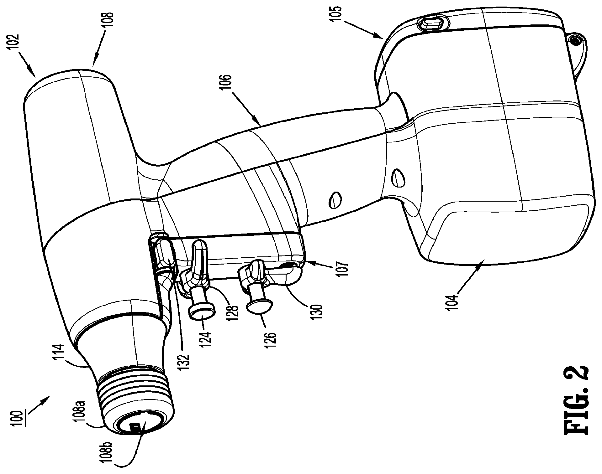
FIG. 2 is a perspective view of the surgical device of FIG. 1;
FIG. 3 is a perspective view, with parts separated, of the surgical device of FIGS. 1 and 2;
FIG. 4 is a perspective view of a battery for use in the surgical device of FIGS. 1-3;
FIG. 5 is a perspective view of the surgical device of FIGS. 1-3, with a housing thereof removed;
FIG. 6 is a perspective view of the connecting ends of each of the surgical device and the adapter assembly, illustrating a connection therebetween;
FIG. 7 is a cross-sectional view of the surgical device of FIGS. 1-3, as taken through 7-7 of FIG. 2;
FIG. 8 is a cross-sectional view of the surgical device of FIGS. 1-3, as taken through 8-8 of FIG. 2;
FIG. 9 is a perspective view of the adapter assembly of FIG. 1;
FIG. 10 is a perspective view, with parts separated, of the adapter assembly of FIGS. 1 and 9;
FIG. 11 is a perspective view, with parts separated, of a drive coupling assembly of the adapter assembly of FIGS. 1 and 9;
FIG. 12 is a perspective view, with parts separated, of a distal portion of the adapter assembly of FIGS. 1 and 9;
FIG. 13 is a schematic illustration of the outputs to the LED's; selection of motor (to select clamping/cutting, rotation or articulation); and selection of the drive motors to perform a function selected;
FIG. 14 is a rear, perspective view of an alternate embodiment of an adapter assembly and an alternate embodiment of an end effector incorporating novel aspects of the present disclosure, for use with the hand-held, electromechanical surgical device of FIG. 1; and
FIG. 15 is a rear, perspective view of a proximal portion of the adapter assembly of FIG. 14, with a housing removed therefrom.
DETAILED DESCRIPTION OF EMBODIMENTS
Embodiments of the presently disclosed surgical devices, and adapter assemblies for electromechanical surgical devices and/or handle assemblies are described in detail with reference to the drawings, in which like reference numerals designate identical or corresponding elements in each of the several views. As used herein the term "distal" refers to that portion of the adapter assembly or surgical device, or component thereof, farther from the user, while the term "proximal" refers to that portion of the adapter assembly or surgical device, or component thereof, closer to the user.
A surgical device, in accordance with an embodiment of the present disclosure, is generally designated as 100, and is in the form of a powered, hand-held, electromechanical instrument configured for selective attachment thereto of a plurality of different end effectors that are each configured for actuation and manipulation by the powered, hand-held, electromechanical surgical instrument.
As illustrated in FIG. 1, surgical device 100 is configured for selective connection with any one of a number of adapter assemblies 200 (whether intelligent or not intelligent, i.e., dumb), and, in turn, each unique adapter assembly 200 is configured for selective connection with any number of unique end effectors or single use loading units 300.
As illustrated in FIGS. 1-3, surgical device 100 includes a handle housing 102 having a lower housing portion 104, an intermediate housing portion 106 extending from and/or supported on lower housing portion 104, and an upper housing portion 108 extending from and/or supported on intermediate housing portion 106. Intermediate housing portion 106 and upper housing portion 108 are separated into a distal half-section 110a that is integrally formed with and extending from the lower portion 104, and a proximal half-section 110b connectable to distal half-section 110a by a plurality of fasteners. When joined, distal and proximal half-sections 110a, 110b define a handle housing 102 having a cavity 102a therein in which a circuit board 150 and a drive mechanism 160 is situated.
Distal and proximal half-sections 110a, 110b are divided along a plane that traverses a longitudinal axis "X" of upper housing portion 108, as seen in FIG. 1.
Handle housing 102 includes a gasket 112 extending completely around a rim of distal half-section and/or proximal half-section 110a, 110b and being interposed between distal half-section 110a and proximal half-section 110b. Gasket 112 seals the perimeter of distal half-section 110a and proximal half-section 110b. Gasket 112 functions to establish an air-tight seal between distal half-section 110a and proximal half-section 110b such that circuit board 150 and drive mechanism 160 are protected from sterilization and/or cleaning procedures.
In this manner, the cavity 102a of handle housing 102 is sealed along the perimeter of distal half-section 110a and proximal half-section 110b yet is configured to enable easier, more efficient assembly of circuit board 150 and a drive mechanism 160 in handle housing 102.
Intermediate housing portion 106 of handle housing 102 provides a housing in which circuit board 150 is situated. Circuit board 150 is configured to control the various operations of surgical device 100, as will be set forth in additional detail below.
Lower housing portion 104 of surgical device 100 defines an aperture (not shown) formed in an upper surface thereof and which is located beneath or within intermediate housing portion 106. The aperture of lower housing portion 104 provides a passage through which wires 152 pass to electrically interconnect electrical components (a battery 156, as illustrated in FIG. 4, a circuit board 154, as illustrated in FIG. 3, etc.) situated in lower housing portion 104 with electrical components (circuit board 150, drive mechanism 160, etc.) situated in intermediate housing portion 106 and/or upper housing portion 108.
Handle housing 102 includes a gasket 103 disposed within the aperture of lower housing portion 104 (not shown) thereby plugging or sealing the aperture of lower housing portion 104 while allowing wires 152 to pass therethrough. Gasket 103 functions to establish an air-tight seal between lower housing portion 106 and intermediate housing portion 108 such that circuit board 150 and drive mechanism 160 are protected from sterilization and/or cleaning procedures.
As shown, lower housing portion 104 of handle housing 102 provides a housing in which a rechargeable battery 156, is removably situated. Battery 156 is configured to supply power to any of the electrical components of surgical device 100. Lower housing portion 104 defines a cavity (not shown) into which battery 156 is inserted. Lower housing portion 104 includes a door 105 pivotally connected thereto for closing cavity of lower housing portion 104 and retaining battery 156 therein. While a battery 156 is shown, it is contemplated that the surgical device may be powered by any number of power sources, such as, for example, a fuel cell, a power cord connected to an external power source, etc.
With reference to FIGS. 3 and 5, distal half-section 110a of upper housing portion 108 defines a nose or connecting portion 108a. A nose cone 114 is supported on nose portion 108a of upper housing portion 108. Nose cone 114 is fabricated from a transparent material. An illumination member 116 is disposed within nose cone 114 such that illumination member 116 is visible therethrough. Illumination member 116 is in the form of a light emitting diode printed circuit board (LED PCB). Illumination member 116 is configured to illuminate multiple colors with a specific color pattern being associated with a unique discrete event.
Upper housing portion 108 of handle housing 102 provides a housing in which drive mechanism 160 is situated. As illustrated in FIG. 5, drive mechanism 160 is configured to drive shafts and/or gear components in order to perform the various operations of surgical device 100. In particular, drive mechanism 160 is configured to drive shafts and/or gear components in order to selectively move tool assembly 304 of end effector 300 (see FIGS. 1 and 20) relative to proximal body portion 302 of end effector 300, to rotate end effector 300 about a longitudinal axis "X" (see FIG. 3) relative to handle housing 102, to move anvil assembly 306 relative to cartridge assembly 308 of end effector 300, and/or to fire a stapling and cutting cartridge within cartridge assembly 308 of end effector 300.
The drive mechanism 160 includes a selector gearbox assembly 162 that is located immediately proximal relative to adapter assembly 200. Proximal to the selector gearbox assembly 162 is a function selection module 163 having a first motor 164 that functions to selectively move gear elements within the selector gearbox assembly 162 into engagement with an input drive component 165 having a second motor 166.
As illustrated in FIGS. 1-4, and as mentioned above, distal half-section 110a of upper housing portion 108 defines a connecting portion 108a configured to accept a corresponding drive coupling assembly 210 of adapter assembly 200.
As illustrated in FIGS. 6-8, connecting portion 108a of surgical device 100 has a cylindrical recess 108b that receives a drive coupling assembly 210 of adapter assembly 200 when adapter assembly 200 is mated to surgical device 100. Connecting portion 108a houses three rotatable drive connectors 118, 120, 122.
When a selected adapter assembly 200 is mated to surgical device 100, at least one of the rotatable drive connectors 118, 120, 122 of surgical device 100 couples with a corresponding rotatable connector sleeve, such as, for example connector sleeves 218, 220, 222 of adapter assembly 200 (see FIG. 6). In regard to adapter assembly 200, the interface between corresponding first drive connector 118 and first connector sleeve 218, the interface between corresponding second drive connector 120 and second connector sleeve 220, and the interface between corresponding third drive connector 122 and third connector sleeve 222 are keyed such that rotation of each of drive connectors 118, 120, 122 of surgical device 100 causes a corresponding rotation of the corresponding connector sleeve 218, 220, 222 of adapter assembly 200.
The mating of drive connectors 118, 120, 122 of surgical device 100 with connector sleeves 218, 220, 222 of adapter assembly 200 allows rotational forces to be independently transmitted via each of the three respective connector interfaces. The drive connectors 118, 120, 122 of surgical device 100 are configured to be independently rotated by drive mechanism 160. In this regard, the function selection module 163 of drive mechanism 160 selects which drive connector or connectors 118, 120, 122 of surgical device 100 is to be driven by the input drive component 165 of drive mechanism 160.
Since each of drive connectors 118, 120, 122 of surgical device 100 has a keyed and/or substantially non-rotatable interface with respective connector sleeves 218, 220, 222 of adapter assembly 200, when adapter assembly 200 is coupled to surgical device 100, rotational force(s) are selectively transferred from drive mechanism 160 of surgical device 100 to adapter assembly 200.
The selective rotation of drive connector(s) 118, 120 and/or 122 of surgical device 100 allows surgical device 100 to selectively actuate different functions of end effector 300. As will be discussed in greater detail below, selective and independent rotation of first drive connector 118 of surgical device 100 corresponds to the selective and independent opening and closing of tool assembly 304 of end effector 300, and driving of a stapling/cutting component of tool assembly 304 of end effector 300. Also, the selective and independent rotation of second drive connector 120 of surgical device 100 corresponds to the selective and independent articulation of tool assembly 304 of end effector 300 transverse to longitudinal axis "X" (see FIG. 3). Additionally, the selective and independent rotation of third drive connector 122 of surgical device 100 corresponds to the selective and independent rotation of end effector 300 about longitudinal axis "X" (see FIG. 3) relative to handle housing 102 of surgical device 100.
As mentioned above and as illustrated in FIGS. 5 and 8, drive mechanism 160 includes a selector gearbox assembly 162; a function selection module 163, located proximal to the selector gearbox assembly 162, that functions to selectively move gear elements within the selector gearbox assembly 162 into engagement with second motor 166. Thus, drive mechanism 160 selectively drives one of drive connectors 118, 120, 122 of surgical device 100 at a given time.
As illustrated in FIGS. 1-3 and FIG. 9, handle housing 102 supports a trigger housing 107 on a distal surface or side of intermediate housing portion 108. Trigger housing 107, in cooperation with intermediate housing portion 108, supports a pair of finger-actuated control buttons 124, 126 and rocker devices 128, 130. In particular, trigger housing 107 defines an upper aperture 124a for slidably receiving a first control button 124, a lower aperture 126b for slidably receiving a second control button 126, and a includes a fire button or safety switch 132.
Each one of the control buttons 124, 126 and rocker devices 128, 130 and safety switch 132 includes a respective magnet (not shown) that is moved by the actuation of an operator. In addition, circuit board 150 includes, for each one of the control buttons 124, 126 and rocker devices 128, 130, and for the safety switch 132, respective Hall-effect switches 150a-150g that are actuated by the movement of the magnets in the control buttons 124, 126 and rocker devices 128, 130, and safety switch 132.
In particular, located immediately proximal to the control button 124 is a first Hall-effect switch 150c (see FIGS. 3 and 7) that is actuated upon the movement of a magnet within the control button 124 upon the operator actuating control button 124. The actuation of first Hall-effect switch 150c, corresponding to control button 124, causes circuit board 150 to provide appropriate signals to function selection module 163 and input drive component 165 of the drive mechanism 160 to close a tool assembly 304 of end effector 300 and/or to fire a stapling/cutting cartridge within tool assembly 304 of end effector 300.
Also, located immediately proximal to rocker device 128 is a second and a third Hall-effect switch 150b, 150d (see FIGS. 3 and 7) that are actuated upon the movement of a magnet (not shown) within rocker device 128 upon the operator actuating rocker device 128. The actuation of second Hall-effect switch 150b, corresponding to an actuation of rocker device 128 in a first direction, causes circuit board 150 to provide appropriate signals to function selection module 163 and input drive component 165 of drive mechanism 160 to articulate tool assembly 304 relative to body portion 302 of end effector 300 in a relatively left direction. The actuation of third Hall-effect switch 150d, corresponding to an actuation of rocker device 128 in a second direction (opposite the first direction), causes circuit board 150 to provide appropriate signals to function selection module 163 and input drive component 165 of drive mechanism 160 to articulate tool assembly 304 relative to body portion 302 of end effector 300 in a relatively right direction. Advantageously, movement of rocker device 128 in a first direction causes tool assembly 304 to articulate relative to body portion 302 in a first direction, while movement of rocker device 128 in an opposite, e.g., second, direction causes tool assembly 304 to articulate relative to body portion 302 in an opposite, e.g., second, direction.
Furthermore, located immediately proximal to control button 126 is a fourth Hall-effect switch 150f (see FIGS. 3 and 7) that is actuated upon the movement of a magnet (not shown) within control button 126 upon the operator actuating control button 126. The actuation of fourth Hall-effect switch 150f, corresponding to control button 126, causes circuit board 150 to provide appropriate signals to function selection module 163 and input drive component 165 of drive mechanism 160 to open tool assembly 304 of end effector 300.
In addition, located immediately proximal to rocker device 130 is a fifth and a sixth Hall-effect switch 150e, 150g (see FIGS. 3 and 7) that are actuated upon the movement of a magnet (not shown) within rocker device 130 upon the operator actuating rocker device 130. The actuation of fifth Hall-effect switch 150e, corresponding to an actuation of rocker device 130 in a first direction, causes circuit board 150 to provide appropriate signals to function selection module 163 and input drive component 165 of drive mechanism 160 to rotate end effector 300 relative to handle housing 102 of surgical device 100 in a first direction (i.e., counter clockwise). The actuation of sixth Hall-effect switch 150g, corresponding to an actuation of rocker device 130 in a second direction (opposite the first direction), causes circuit board 150 to provide appropriate signals to function selection module 163 and input drive component 165 of drive mechanism 160 to rotate end effector 300 relative to handle housing 102 of surgical device 100 in a second direction (i.e., clockwise). Specifically, movement of rocker device 130 in a first direction causes end effector 300 to rotate relative to handle housing 102 in a first direction, while movement of rocker device 130 in an opposite, e.g., second, direction causes end effector 300 to rotate relative to handle housing 102 in an opposite, e.g., second, direction.
As seen in FIGS. 1-3 and 7, as mentioned above, surgical device 100 includes a fire button or safety switch 132 supported on or in an upper portion of trigger housing 107. In use, tool assembly 304 of end effector 300 is actuated between opened and closed conditions as needed and/or desired. In order to fire end effector 300, to expel fasteners therefrom when tool assembly 304 of end effector 300 is in a closed condition, safety switch 132 is depressed thereby moving a magnet (not shown), supported therein, to actuate a seventh Hall-effect switch 150a, which in turn, instructs surgical device 100 that end effector 300 is ready to expel fasteners therefrom (i.e., places surgical device 100 in a firing mode).
As illustrated in FIGS. 1 and 9-12, surgical device 100 is configured for selective connection with adapter assembly 200, and, in turn, adapter assembly 200 is configured for selective connection with end effector 300. Reference may be made to U.S. patent application Ser. No. 13/484,975, filed on May 31, 2012, entitled "Hand Held Surgical Handle Assembly, Surgical Adapters for Use Between Surgical Handle Assembly and Surgical End Effectors, and Methods of Use," the entire content of which is incorporated herein by reference, for a detailed discussion of the construction and operation of adapter assembly 200.
Adapter assembly 200 is configured to convert a rotation of either of drive connectors 120 and 122 of surgical device 100 into axial translation useful for operating a drive assembly 360 and an articulation link 366 of end effector 300.
Adapter assembly 200 includes a first drive transmitting/converting assembly for interconnecting third rotatable drive connector 122 of surgical device 100 and a first axially translatable drive member of end effector 300, wherein the first drive transmitting/converting assembly converts and transmits a rotation of third rotatable drive connector 122 of surgical device 100 to an axial translation of the first axially translatable drive assembly 360 of end effector 300 for firing.
Adapter assembly 200 includes a second drive transmitting/converting assembly for interconnecting second rotatable drive connector 120 of surgical device 100 and a second axially translatable drive member of end effector 300, wherein the second drive transmitting/converting assembly converts and transmits a rotation of second rotatable drive connector 120 of surgical device 100 to an axial translation of articulation link 366 of end effector 300 for articulation.
Turning now to FIGS. 9 and 10, adapter assembly 200 includes a knob housing 202 and an outer tube 206 extending from a distal end of knob housing 202. Knob housing 202 and outer tube 206 are configured and dimensioned to house the components of adapter assembly 200. Outer tube 206 is dimensioned for endoscopic insertion, in particular, that outer tube is passable through a typical trocar port, cannula or the like. Knob housing 202 is dimensioned to not enter the trocar port, cannula of the like.
Knob housing 202 is configured and adapted to connect to connecting portion 108a of upper housing portion 108 of distal half-section 110a of surgical device 100.
As seen in FIGS. 9-11, adapter assembly 200 includes a surgical device drive coupling assembly 210 at a proximal end thereof and to an end effector coupling assembly 230 at a distal end thereof. Drive coupling assembly 210 includes a distal drive coupling housing 210a and a proximal drive coupling housing 210b rotatably supported, at least partially, in knob housing 202. Drive coupling assembly 210 rotatably supports a first rotatable proximal drive shaft 212, a second rotatable proximal drive shaft 214, and a third rotatable proximal drive shaft 216 therein.
Proximal drive coupling housing 210b is configured to rotatably support first, second and third connector sleeves 218, 220 and 222, respectively. Each of connector sleeves 218, 220, 222 is configured to mate with respective first, second and third drive connectors 118, 120, 122 of surgical device 100, as described above. Each of connector sleeves 218, 220, 222 is further configured to mate with a proximal end of respective first, second and third proximal drive shafts 212, 214, 216.
With reference to FIGS. 9 and 12, adapter assembly 200 further includes a lock mechanism for fixing the axial position and radial orientation of drive tube 246 for the connection and disconnection of end effector 300 thereto. The lock mechanism includes a button 282 slidably supported on knob housing 202. Lock button 282 is connected to an actuation bar 284 that extends longitudinally through outer tube 206. Actuation bar 284 is interposed between outer tube 206 and inner housing tube 206a. Actuation bar 284 moves upon a movement of lock button 282. Actuation bar 284 includes a distal portion 284a defining a window 284b therein.
As illustrated in FIG. 12, the lock mechanism further includes a lock out 286 supported on distal coupling assembly 230 at a location in registration with window 284b of distal portion 284a of actuation bar 284. Lock out 286 includes a tab extending toward connection member 247 of drive tube 246. The tab of lock out 286 is configured and dimensioned to selectively engage a cut-out formed in connection member 247 of drive tube 246. Lock mechanism 280 further includes a biasing member 288 tending to maintain lock out 286 and the tab thereof spaced away from the cut-out formed in connection member 247 of drive tube 246.
In operation, in order to lock the position and/or orientation of drive tube 246, a user moves lock button 282 from a distal position to a proximal position, thereby causing a cam surface of actuation bar 284 to engage lock arm 286 and urge lock out 286 toward drive tube 246, against the bias of biasing member 288, such that the tab of lock out 286 is received in the cut-out formed in connection member 247 of drive tube 246. In this manner, drive tube 246 is prevented from distal and/or proximal movement.
When lock button 282 is moved from the proximal position to the distal position, the cam surface is disengaged from lock out 286 thereby allowing biasing member 288 to urge lock out 286 and the tab thereof out of the cut-out formed in connection member 247 of drive tube 246.
As seen in FIGS. 6 and 12, adapter assembly 200 includes a pair of electrical contact pins 290a, 290b for electrical connection to a corresponding electrical plug 190a, 190b disposed in connecting portion 108a of surgical device 100. Electrical contacts 290a, 290b serve to allow for calibration and communication of necessary operating parameters and/or life-cycle information, of adapter assembly 200, to circuit board 150 of surgical device 100 via electrical plugs 190a, 190b that are electrically connected to circuit board 150. Adapter assembly 200 further includes a circuit board 292 supported in knob housing 202 and which is in electrical communication with electrical contact pins 290a, 290b. Circuit board 292 of adapter assembly 200 stores the operating parameters and/or life cycle information for each unique adapter assembly thereon.
Circuit board 292 may include a volatile and/or non-volatile memory for storing either the operating parameters and/or life cycle information, whether the operating parameters and/or life cycle information is original or updated (during or following use).
It is further contemplated that adapter assembly 200 may include a power source or the like, i.e., battery (not shown) which is electrically connected to circuit board 292. It is contemplated that the battery of adapter assembly 200 may provide power to adapter assembly 200 which is different from any power provided from battery 156 of surgical device 100. For example, the batter of adapter assembly 200 may be used to power any mechanical motors in the adapter assembly, power any visual devices or displays supported on or in adapter assembly, or power any audible devices in the adapter assembly.
In accordance with the present disclosure, the operating parameters for adapter assembly 200 include identification information relating to the adapter assembly (e.g., model number, serial number, etc.); dimensions of the adapter assembly; specific designations for which rotational input received from surgical device 100 will perform which specific function in the adapter assembly; what the maximum force is that can be delivered from surgical device 100 to the adapter assembly; and any other required information.
Additionally, in accordance with the present disclosure, the life-cycle information for adapter assembly 200 may include a number of revolutions experienced by connector sleeves 218, 220, 222 of the adapter assembly; a number of cleaning cycles (e.g., hand-washing, dishwashing, irradiating, sterilizing, autoclaving, with or without cleaning fluids, etc.) of the adapter assembly; an assembly date of the adapter assembly; and any repair/maintenance dates of the shaft assembly.
In use, any or all of the operating parameters and/or the life-cycle information may be transmitted from adapter assembly 200 to surgical device 100, via the electrical interface between electrical plugs 190a, 190b of surgical device 100 and electrical contact pins 290a, 290b of the adapter assembly 200, when adapter assembly 200 and surgical device 100 are connected to one another. Alternatively, any or all of the operating parameters and/or the life-cycle information may be transmitted from adapter assembly 200 to surgical device 100 during a calibration sequence of surgical device 100.
While an electrical interface between surgical device 100 and adapter assembly 200, including electrical plugs 190a, 190b and electrical contact pins 290a, 290b, is shown and described, it is contemplated that any other form or telecommunication is within the scope of the present disclosure, for transmitting any or all of the operating parameters and/or the life-cycle information from adapter assembly 200 to surgical device 100, such as, for example, wireless communication, near-field communication, Blue Tooth communication, etc.
In this manner, in accordance with the present disclosure, as new adapter assemblies are developed for a common surgical device (i.e., surgical device 100), any new unique operating parameters and/or the life-cycle information of the new adapter assembly may be specifically associated therewith and transmitted or communicated to the surgical device when the new adapter assembly is connected thereto or during any calibration sequence of the assembled surgical device 100 and new adapter assembly.
In accordance with the present disclosure, it is contemplated that any or all of the operating parameters and/or the life-cycle information may update automatically, may be manually updated by a technician following each surgical use, wherein the adapter assembly may be electrically connected to a computer interface via electrical contact pins 290a, 290b or other communication interface.
In this manner, surgical device 100, being an intelligent surgical instrument, is able to properly handle new (i.e., not yet developed) adapter assemblies, without having to be pre-programmed with required operating parameters for said new adapter assemblies.
In use, when a button of surgical device 100 is activated by the user, the software checks predefined conditions. If conditions are met, the software controls the motors and delivers mechanical drive to the attached end effector (e.g., surgical stapler), via an adapter assembly, which can then open, close, rotate, articulate or fire depending on the function of the pressed button. The software also provides feedback to the user by turning colored lights on or off in a defined manner to indicate the status of surgical device 100, adapter assembly 200 and/or end effector 300.
A high level electrical architectural view of the system is displayed below in Schematic "A" and shows the connections to the various hardware and software interfaces. Inputs from presses of buttons 124, 126 and from motor encoders of the drive shaft are shown on the left side of Schematic "A". The microcontroller contains the device software that operates surgical device 100, adapter assembly 200 and/or end effector 300. The microcontroller receives inputs from and sends outputs to a MicroLAN, an Ultra ID chip, a Battery ID chip, and Adaptor ID chips.
The MicroLAN, the Ultra ID chip, the Battery ID chip, and the Adaptor ID chips control surgical device 100, adapter assembly 200 and/or end effector 300 as follows: MicroLAN--Serial 1-wire bus communication to read/write system component ID information. Ultra ID chip--identifies surgical device 100 and records usage information. Battery ID chip--identifies the Battery 156 and records usage information. Adaptor ID chip--identifies the type of adapter assembly 200, records the presence of an end effector 300, and records usage information.
The right side of the schematic illustrated in FIG. 13 indicates outputs to the LED's; selection of motor (to select clamping/cutting, rotation or articulation); and selection of the drive motors to perform the function selected.
As illustrated in FIG. 1, the end effector is designated as 300. End effector 300 is configured and dimensioned for endoscopic insertion through a cannula, trocar or the like. In particular, in the embodiment illustrated in FIG. 1, end effector 300 may pass through a cannula or trocar when end effector 300 is in a closed condition.
End effector 300 includes a proximal body portion 302 and a tool assembly 304. Proximal body portion 302 is releasably attached to a distal coupling 230 of adapter assembly 200 and tool assembly 304 is pivotally attached to a distal end of proximal body portion 302. Tool assembly 304 includes an anvil assembly 306 and a cartridge assembly 308. Cartridge assembly 308 is pivotal in relation to anvil assembly 306 and is movable between an open or unclamped position and a closed or clamped position for insertion through a cannula of a trocar.
Reference may be made to U.S. Pat. No. 7,819,896, filed on Aug. 31, 2009, entitled "TOOL ASSEMBLY FOR A SURGICAL STAPLING DEVICE", the entire content of which is incorporated herein by reference, for a detailed discussion of the construction and operation of end effector 300.
Since adapter assembly 200 is reusable, prior to each use, at least adapter assembly 200 must be sterilized using known sterilization techniques and methods (e.g., hand-washing, dishwashing and/or then autoclaving using cleaning fluids or the like).
Turning now to FIGS. 14-15, an alternate embodiment of an adapter assembly 200a and an alternate embodiment of an end effector 300a, incorporating novel aspects of the present disclosure, for use with the hand-held, electromechanical surgical device 100, is shown. Reference may be made to U.S. patent application Ser. No. 13/769,419, filed on Feb. 18, 2013, entitled "APPARATUS FOR ENDOSCOPIC PROCEDURES", the entire content of which is incorporated herein by reference in its entirety, for a detailed discussion of the construction and operation of adapter assembly 200a and end effector 300a.
As seen specifically in FIG. 15, adapter assembly 200a includes a circuit board 292 and electrical contacts 290a, 290b, similar to adapter assembly 200.
While the specific operation and functionality of adapter assembly 200a may be different than adapter assembly 200, in order to operate end effector 300a, circuit board 292 of adapter assembly 200a may store operating parameters and/or life cycle information which is/are unique to adapter assembly 200a.
Reference may additionally be made to U.S. patent application Ser. No. 13/769,414, filed on Feb. 18, 2013, entitled "APPARATUS FOR ENDOSCOPIC PROCEDURES"; and to U.S. patent application Ser. No. 13/799,379, filed on Mar. 13, 2013, entitled "APPARATUS FOR ENDOSCOPIC PROCEDURES", the entire content of each of which being incorporated herein by reference in their entirety, for a detailed discussion of the construction and operation of alternate adapter assemblies and/or end effectors, incorporating novel aspects of the present disclosure, for use with the hand-held, electromechanical surgical device 100.
In accordance with the present disclosure, it is contemplated that an operating room or the like would be supplied with an electromechanical surgical system including at least one surgical device 100; a plurality of unique and/or diverse adapter assemblies, in accordance with the present disclosure; and a plurality of diverse end effectors, capable of performing a number of different surgical procedures. In use, depending on the surgical procedure to be performed, the surgeon will select a desired and appropriate end effector for performing the particular surgical procedure; the surgeon will select an appropriate adapter assembly for interconnecting the particular end effector and the surgical device 100; and the surgeon (or other operating room staff) will connect the appropriate adapter assembly to the surgical device 100.
It is then contemplated that the appropriate adapter assembly will communicate with surgical device 100, wherein the operating parameters and/or life cycle information for the appropriate adapter assembly will be transmitted or communicated from circuit board 292 of the appropriate adapter assembly to surgical device 100 for processing thereby. If the operating parameters and/or life cycle information for the appropriate adapter assembly produce no error signals from surgical device 100, during a calibration and/or initialization sequence, surgical device 100 may produce a ready signal, whereby the surgeon (or other operating room staff) will connect the selected end effector to the appropriate adapter assembly.
It will be understood that various modifications may be made to the embodiments of the presently disclosed adapter assemblies. Therefore, the above description should not be construed as limiting, but merely as exemplifications of embodiments. Those skilled in the art will envision other modifications within the scope and spirit of the present disclosure.
* * * * *
D00000
D00001
D00002
D00003
D00004
D00005
D00006
D00007
D00008
D00009
D00010
D00011
D00012

D00013

D00014

XML
uspto.report is an independent third-party trademark research tool that is not affiliated, endorsed, or sponsored by the United States Patent and Trademark Office (USPTO) or any other governmental organization. The information provided by uspto.report is based on publicly available data at the time of writing and is intended for informational purposes only.
While we strive to provide accurate and up-to-date information, we do not guarantee the accuracy, completeness, reliability, or suitability of the information displayed on this site. The use of this site is at your own risk. Any reliance you place on such information is therefore strictly at your own risk.
All official trademark data, including owner information, should be verified by visiting the official USPTO website at www.uspto.gov. This site is not intended to replace professional legal advice and should not be used as a substitute for consulting with a legal professional who is knowledgeable about trademark law.