Authentication of a suspect object using extracted native features
Ross , et al. February 9, 2
U.S. patent number 10,915,749 [Application Number 16/041,710] was granted by the patent office on 2021-02-09 for authentication of a suspect object using extracted native features. This patent grant is currently assigned to ALITHEON, INC.. The grantee listed for this patent is ALITHEON, INC.. Invention is credited to Brian Elmenhurst, John Forbes, David Ross, Heather Wheelock Ross, Mark Tocci.


| United States Patent | 10,915,749 |
| Ross , et al. | February 9, 2021 |
Authentication of a suspect object using extracted native features
Abstract
A forgery detection system includes a computer server and a database system of digital fingerprint records corresponding to forged or altered objects of a given object type. Using the computer server, a digital image of a suspect object of the given object type is accessed, an authentication region is selected, and a native feature within the authentication region is extracted. The native feature describes physical characteristics of the authentication region without recognizing content that appears in the authentication region. The computer server forms a feature vector to represent the native feature in a compact form and queries the database system to obtain a result responsive to digital fingerprint records that match the feature vector. Each matching digital fingerprint record is counted, and if the count of fraud indicator matches crosses a predetermined threshold indicating a confidence level that the suspect object is forged or altered, a report based is generated and communicated to a user interface.
| Inventors: | Ross; David (Bellevue, WA), Elmenhurst; Brian (Bellevue, WA), Tocci; Mark (Bellevue, WA), Forbes; John (Bellevue, WA), Ross; Heather Wheelock (Bellevue, WA) | ||||||||||
|---|---|---|---|---|---|---|---|---|---|---|---|
| Applicant: |
|
||||||||||
| Assignee: | ALITHEON, INC. (Bellevue,
WA) |
||||||||||
| Family ID: | 1000005351937 | ||||||||||
| Appl. No.: | 16/041,710 | ||||||||||
| Filed: | July 20, 2018 |
Prior Publication Data
| Document Identifier | Publication Date | |
|---|---|---|
| US 20180349694 A1 | Dec 6, 2018 | |
Related U.S. Patent Documents
| Application Number | Filing Date | Patent Number | Issue Date | ||
|---|---|---|---|---|---|
| 15044034 | Feb 15, 2016 | 10043073 | |||
| 14531307 | Feb 28, 2017 | 9582714 | |||
| 14290653 | May 24, 2016 | 9350552 | |||
| 13410753 | Jul 8, 2014 | 8774455 | |||
| 13618362 | Oct 6, 2015 | 9152862 | |||
| 61898780 | Nov 1, 2013 | ||||
| 61914722 | Dec 11, 2013 | ||||
| 61448465 | Mar 2, 2011 | ||||
| 61535084 | Sep 15, 2011 | ||||
| Current U.S. Class: | 1/1 |
| Current CPC Class: | G06K 9/52 (20130101); G06T 7/90 (20170101); G06F 16/5846 (20190101); G06T 7/60 (20130101); G06K 9/00483 (20130101); G06F 16/583 (20190101); G06F 16/2468 (20190101); G06K 9/3216 (20130101); H04L 9/3247 (20130101); G06K 9/4652 (20130101); B07C 5/3422 (20130101); G06Q 50/32 (20130101); G06K 2209/01 (20130101) |
| Current International Class: | G06K 9/00 (20060101); G06K 9/52 (20060101); G06K 9/46 (20060101); H04L 9/32 (20060101); B07C 5/342 (20060101); G06K 9/32 (20060101); G06F 16/2458 (20190101); G06F 16/583 (20190101); G06T 7/60 (20170101); G06T 7/90 (20170101); G06Q 50/32 (20120101) |
References Cited [Referenced By]
U.S. Patent Documents
| 4218674 | August 1980 | Brosow et al. |
| 4423415 | December 1983 | Goldman |
| 4677435 | June 1987 | Causse D'Agraives et al. |
| 4700400 | October 1987 | Ross |
| 4921107 | May 1990 | Hofer |
| 5031223 | July 1991 | Rosenbaum et al. |
| 5079714 | January 1992 | Manduley et al. |
| 5393939 | February 1995 | Nasuta, Jr. et al. |
| 5422821 | June 1995 | Allen et al. |
| 5514863 | May 1996 | Williams |
| 5518122 | May 1996 | Tilles et al. |
| 5521984 | May 1996 | Denenberg et al. |
| 5703783 | December 1997 | Allen et al. |
| 5719939 | February 1998 | Tel |
| 5734568 | March 1998 | Borgendale et al. |
| 5745590 | April 1998 | Pollard |
| 5883971 | March 1999 | Bolle et al. |
| 5923848 | July 1999 | Goodhand et al. |
| 5974150 | October 1999 | Kaish et al. |
| 6205261 | March 2001 | Goldberg |
| 6246794 | June 2001 | Kagehiro et al. |
| 6292709 | September 2001 | Uhl et al. |
| 6327373 | December 2001 | Yura |
| 6343327 | January 2002 | Daniels, Jr. et al. |
| 6360001 | March 2002 | Berger et al. |
| 6370259 | April 2002 | Hobson et al. |
| 6400805 | June 2002 | Brown et al. |
| 6424728 | July 2002 | Ammar |
| 6434601 | August 2002 | Rollins |
| 6470091 | October 2002 | Koga et al. |
| 6539098 | March 2003 | Baker et al. |
| 6549892 | April 2003 | Sansone |
| 6597809 | July 2003 | Ross et al. |
| 6643648 | November 2003 | Ross et al. |
| 6697500 | February 2004 | Woolston et al. |
| 6741724 | May 2004 | Bruce et al. |
| 6768810 | July 2004 | Emanuelsson et al. |
| 6778703 | August 2004 | Zlotnick |
| 6805926 | October 2004 | Cote et al. |
| 6816602 | November 2004 | Coffelt et al. |
| 6829369 | December 2004 | Poulin et al. |
| 6961466 | November 2005 | Imagawa et al. |
| 6985926 | January 2006 | Ferlauto et al. |
| 7016532 | March 2006 | Boncyk et al. |
| 7031519 | April 2006 | Elmenhurst |
| 7096152 | August 2006 | Ong |
| 7120302 | October 2006 | Billester |
| 7121458 | October 2006 | Avant et al. |
| 7152047 | December 2006 | Nagel |
| 7171049 | January 2007 | Snapp |
| 7204415 | April 2007 | Payne et al. |
| 7212949 | May 2007 | Bachrach |
| 7333987 | February 2008 | Ross et al. |
| 7343623 | March 2008 | Ross |
| 7356162 | April 2008 | Caillon |
| 7379603 | May 2008 | Ross et al. |
| 7436979 | October 2008 | Bruce |
| 7477780 | January 2009 | Boncyk et al. |
| 7518080 | April 2009 | Amato |
| 7602938 | October 2009 | Proloski |
| 7674995 | March 2010 | Desprez et al. |
| 7676433 | March 2010 | Ross et al. |
| 7680306 | March 2010 | Boutant et al. |
| 7720256 | May 2010 | Desprez et al. |
| 7726457 | June 2010 | Maier et al. |
| 7726548 | June 2010 | DeLaVergne |
| 7748029 | June 2010 | Ross |
| 7822263 | October 2010 | Prokoski |
| 7834289 | November 2010 | Orbke |
| 7853792 | December 2010 | Cowburn |
| 8022832 | September 2011 | Vogt et al. |
| 8032927 | October 2011 | Ross |
| 8108309 | January 2012 | Tan |
| 8180174 | May 2012 | Di Venuto |
| 8180667 | May 2012 | Baluja et al. |
| 8194938 | June 2012 | Wechsler et al. |
| 8316418 | November 2012 | Ross |
| 8374399 | February 2013 | Talwerdi |
| 8374920 | February 2013 | Hedges et al. |
| 8391583 | March 2013 | Mennie et al. |
| 8428772 | April 2013 | Miette |
| 8437530 | May 2013 | Mennie et al. |
| 8457354 | June 2013 | Kolar et al. |
| 8477992 | July 2013 | Paul et al. |
| 8520888 | August 2013 | Spitzig |
| 8526743 | September 2013 | Campbell et al. |
| 8774455 | July 2014 | Elmenhurst et al. |
| 9031329 | May 2015 | Farid et al. |
| 9058543 | June 2015 | Campbell |
| 9152862 | October 2015 | Ross |
| 9170654 | October 2015 | Boncyk et al. |
| 9224196 | December 2015 | Duerksen et al. |
| 9234843 | January 2016 | Sopori et al. |
| 9245133 | January 2016 | Durst et al. |
| 9350552 | May 2016 | Elmenhurst et al. |
| 9350714 | May 2016 | Freeman et al. |
| 9361596 | June 2016 | Ross et al. |
| 9558463 | January 2017 | Ross et al. |
| 9582714 | February 2017 | Ross et al. |
| 9646206 | May 2017 | Ross et al. |
| 10043073 | August 2018 | Ross et al. |
| 10199886 | February 2019 | Li et al. |
| 10540664 | January 2020 | Ross et al. |
| 10572883 | February 2020 | Ross et al. |
| 10621594 | April 2020 | Land et al. |
| 2001/0010334 | August 2001 | Park et al. |
| 2001/0054031 | December 2001 | Lee et al. |
| 2002/0015515 | February 2002 | Lichtermann et al. |
| 2002/0073049 | June 2002 | Dutta |
| 2002/0168090 | November 2002 | Bruce et al. |
| 2003/0015395 | January 2003 | Hallowell et al. |
| 2003/0046103 | March 2003 | Amato et al. |
| 2003/0091724 | May 2003 | Mizoguchi |
| 2003/0120677 | June 2003 | Vernon |
| 2003/0138128 | July 2003 | Rhoads |
| 2003/0179931 | September 2003 | Sun |
| 2003/0182018 | September 2003 | Snapp |
| 2003/0208298 | November 2003 | Edmonds |
| 2003/0219145 | November 2003 | Smith |
| 2004/0027630 | February 2004 | Lizotte |
| 2004/0101174 | May 2004 | Sato et al. |
| 2004/0112962 | June 2004 | Farrall et al. |
| 2004/0218791 | November 2004 | Jiang et al. |
| 2004/0218801 | November 2004 | Houle |
| 2005/0007776 | January 2005 | Monk et al. |
| 2005/0038756 | February 2005 | Nagel |
| 2005/0065719 | March 2005 | Khan et al. |
| 2005/0086256 | April 2005 | Owens et al. |
| 2005/0111618 | May 2005 | Sommer et al. |
| 2005/0119786 | June 2005 | Kadaba |
| 2005/0125360 | June 2005 | Tidwell et al. |
| 2005/0131576 | June 2005 | De Leo et al. |
| 2005/0137882 | June 2005 | Cameron et al. |
| 2005/0160271 | July 2005 | Brundage et al. |
| 2005/0169529 | August 2005 | Owechko et al. |
| 2005/0188213 | August 2005 | Xu |
| 2005/0204144 | September 2005 | Mizutani |
| 2005/0251285 | November 2005 | Boyce et al. |
| 2005/0257064 | November 2005 | Boutant et al. |
| 2005/0289061 | December 2005 | Kulakowski et al. |
| 2006/0010503 | January 2006 | Inoue et al. |
| 2006/0083414 | April 2006 | Neumann et al. |
| 2006/0109520 | May 2006 | Gossaye et al. |
| 2006/0131518 | June 2006 | Ross et al. |
| 2006/0177104 | August 2006 | Prokoski |
| 2006/0253406 | November 2006 | Caillon |
| 2007/0071291 | March 2007 | Yumoto et al. |
| 2007/0085710 | April 2007 | Bousquet et al. |
| 2007/0094155 | April 2007 | Dearing |
| 2007/0211651 | September 2007 | Ahmed et al. |
| 2007/0211964 | September 2007 | Agam |
| 2007/0230656 | October 2007 | Lowes et al. |
| 2007/0263267 | November 2007 | Ditt |
| 2007/0269043 | November 2007 | Launay |
| 2007/0282900 | December 2007 | Owens et al. |
| 2008/0008377 | January 2008 | Andel et al. |
| 2008/0011841 | January 2008 | Self et al. |
| 2008/0128496 | June 2008 | Bertranou et al. |
| 2008/0130947 | June 2008 | Ross et al. |
| 2008/0219503 | September 2008 | Di Venuto et al. |
| 2008/0250483 | October 2008 | Lee |
| 2008/0255758 | October 2008 | Graham et al. |
| 2008/0272585 | November 2008 | Conard et al. |
| 2008/0290005 | November 2008 | Bennett et al. |
| 2008/0294474 | November 2008 | Furka |
| 2009/0028379 | January 2009 | Belanger et al. |
| 2009/0057207 | March 2009 | Orbke et al. |
| 2009/0106042 | April 2009 | Maytal et al. |
| 2009/0134222 | May 2009 | Ikeda |
| 2009/0154778 | June 2009 | Lei et al. |
| 2009/0157733 | June 2009 | Kim et al. |
| 2009/0223099 | September 2009 | Versteeg |
| 2009/0232361 | September 2009 | Miller |
| 2009/0245652 | October 2009 | Bastos dos Santos |
| 2009/0271029 | October 2009 | Doutre |
| 2009/0287498 | November 2009 | Choi |
| 2009/0307005 | December 2009 | O'Martin et al. |
| 2010/0027834 | February 2010 | Spitzig et al. |
| 2010/0070527 | March 2010 | Chen |
| 2010/0104200 | April 2010 | Baras et al. |
| 2010/0157064 | June 2010 | Cheng et al. |
| 2010/0163612 | July 2010 | Caillon |
| 2010/0166303 | July 2010 | Rahimi |
| 2010/0174406 | July 2010 | Miette et al. |
| 2010/0286815 | November 2010 | Zimmermann |
| 2011/0026831 | February 2011 | Perronnin et al. |
| 2011/0064279 | March 2011 | Uno |
| 2011/0081043 | April 2011 | Sabol et al. |
| 2011/0091068 | April 2011 | Stuck et al. |
| 2011/0161117 | June 2011 | Busque et al. |
| 2011/0188709 | August 2011 | Gupta et al. |
| 2011/0194780 | August 2011 | Li et al. |
| 2011/0235920 | September 2011 | Iwamoto et al. |
| 2011/0267192 | November 2011 | Goldman et al. |
| 2012/0042171 | February 2012 | White et al. |
| 2012/0089639 | April 2012 | Wang |
| 2012/0130868 | May 2012 | Loken |
| 2012/0177281 | July 2012 | Frew |
| 2012/0185393 | July 2012 | Atsmon et al. |
| 2012/0199651 | August 2012 | Glazer |
| 2012/0242481 | September 2012 | Gernandt et al. |
| 2012/0243797 | September 2012 | Dayer et al. |
| 2012/0250945 | October 2012 | Peng et al. |
| 2013/0212027 | August 2013 | Sharma et al. |
| 2013/0214164 | August 2013 | Zhang et al. |
| 2013/0273968 | October 2013 | Rhoads |
| 2013/0277425 | October 2013 | Sharma et al. |
| 2013/0284803 | October 2013 | Wood et al. |
| 2014/0032322 | January 2014 | Schwieger et al. |
| 2014/0140570 | May 2014 | Ross et al. |
| 2014/0140571 | May 2014 | Elmenhurst et al. |
| 2014/0184843 | July 2014 | Campbell et al. |
| 2014/0201094 | July 2014 | Herrington et al. |
| 2014/0314283 | October 2014 | Harding |
| 2014/0380446 | December 2014 | Niu et al. |
| 2015/0058142 | February 2015 | Lenahan et al. |
| 2015/0078629 | March 2015 | Gottemukkula et al. |
| 2015/0086068 | March 2015 | Mulhearn et al. |
| 2015/0117701 | April 2015 | Ross et al. |
| 2015/0127430 | May 2015 | Hammer, III |
| 2015/0248587 | September 2015 | Oami et al. |
| 2015/0294189 | October 2015 | Benhimane et al. |
| 2015/0309502 | October 2015 | Breitgand et al. |
| 2016/0034914 | February 2016 | Gonen et al. |
| 2016/0055651 | February 2016 | Oami |
| 2016/0057138 | February 2016 | Hoyos et al. |
| 2016/0117631 | April 2016 | McCloskey et al. |
| 2016/0180546 | June 2016 | Kim et al. |
| 2016/0189510 | June 2016 | Hutz |
| 2016/0335520 | November 2016 | Ross et al. |
| 2017/0004444 | January 2017 | Krasko et al. |
| 2017/0032285 | February 2017 | Sharma et al. |
| 2017/0132458 | May 2017 | Short et al. |
| 2017/0243230 | August 2017 | Ross et al. |
| 2017/0243231 | August 2017 | Withrow et al. |
| 2017/0243232 | August 2017 | Ross et al. |
| 2017/0243233 | August 2017 | Land et al. |
| 2017/0253069 | September 2017 | Kerkar et al. |
| 2017/0295301 | October 2017 | Liu et al. |
| 2017/0300905 | October 2017 | Withrow et al. |
| 2017/0344823 | November 2017 | Withrow et al. |
| 2017/0372327 | December 2017 | Withrow |
| 2018/0012008 | January 2018 | Withrow et al. |
| 2018/0018627 | January 2018 | Ross et al. |
| 2018/0018838 | January 2018 | Fankhauser et al. |
| 2018/0024074 | January 2018 | Ranieri et al. |
| 2018/0024178 | January 2018 | House et al. |
| 2018/0047128 | February 2018 | Ross et al. |
| 2018/0053312 | February 2018 | Ross et al. |
| 2018/0121643 | May 2018 | Talwerdi et al. |
| 2018/0144211 | May 2018 | Ross et al. |
| 2018/0315058 | November 2018 | Withrow et al. |
| 2019/0026581 | January 2019 | Leizerson |
| 2019/0034518 | January 2019 | Liu et al. |
| 2019/0034694 | January 2019 | Ross |
| 2019/0102873 | April 2019 | Wang et al. |
| 2019/0228174 | July 2019 | Withrow et al. |
| 2019/0287118 | September 2019 | Ross et al. |
| 2020/0153822 | May 2020 | Land et al. |
| 2020/0226366 | July 2020 | Withrow et al. |
| 2020/0233901 | July 2020 | Crowley et al. |
| 2020/0250395 | August 2020 | Ross et al. |
| 2020/0257791 | August 2020 | Ross et al. |
| 2020/0334689 | October 2020 | Ross et al. |
| 2020/0349379 | November 2020 | Ross |
| 2020/0356772 | November 2020 | Withrow et al. |
| 10 2006 005 927 | Aug 2007 | DE | |||
| 0 439 669 | Aug 1991 | EP | |||
| 0 759 596 | Feb 1997 | EP | |||
| 1 016 548 | Jul 2000 | EP | |||
| 1 719 070 | Apr 2009 | EP | |||
| 2107506 | Oct 2009 | EP | |||
| 2166493 | Mar 2010 | EP | |||
| 2 195 621 | Nov 2013 | EP | |||
| 2 866 193 | Apr 2015 | EP | |||
| 2 257 909 | May 2015 | EP | |||
| 2 869 240 | May 2015 | EP | |||
| 2 869 241 | May 2015 | EP | |||
| 3208744 | Aug 2017 | EP | |||
| 3 249 581 | Nov 2017 | EP | |||
| 3270342 | Jan 2018 | EP | |||
| 3435287 | Jan 2019 | EP | |||
| 2 097 979 | Nov 1982 | GB | |||
| 2482127 | Jan 2012 | GB | |||
| 61-234481 | Oct 1986 | JP | |||
| 2007-213148 | Aug 2007 | JP | |||
| 20120009654 | Feb 2012 | KR | |||
| 2005/086616 | Sep 2005 | WO | |||
| 2006/038114 | Apr 2006 | WO | |||
| 2007/031176 | Mar 2007 | WO | |||
| WO2007028799 | Mar 2007 | WO | |||
| 2007/071788 | Jun 2007 | WO | |||
| 2007/090437 | Aug 2007 | WO | |||
| WO2007090437 | Aug 2007 | WO | |||
| 2007/144598 | Dec 2007 | WO | |||
| WO2007144598 | Dec 2007 | WO | |||
| 2009/030853 | Mar 2009 | WO | |||
| WO2009030853 | Mar 2009 | WO | |||
| WO2009089126 | Jul 2009 | WO | |||
| WO2009115611 | Sep 2009 | WO | |||
| 2010/018464 | Feb 2010 | WO | |||
| WO2010018464 | Feb 2010 | WO | |||
| 2012/145842 | Nov 2012 | WO | |||
| WO2012145842 | Nov 2012 | WO | |||
| 2013/126221 | Aug 2013 | WO | |||
| WO2013126221 | Aug 2013 | WO | |||
| WO2013173408 | Nov 2013 | WO | |||
| 2015/004434 | Jan 2015 | WO | |||
| WO2015004434 | Jan 2015 | WO | |||
| WO2016081831 | May 2016 | WO | |||
Other References
|
Bao et al., "Local Feature based Multiple Object Instance Identification using Scale and Rotation Invariant Implicit Shape Model," 12.sup.th Asian Conference on Computer Vision, Singapore, Singapore, Nov. 1-5, 2014, pp. 600-614. cited by applicant . Beekhof et al., "Secure Surface Identification Codes," Proceedings of the SPIE 6819: Security, Forensics, Steganography, and Watermarking of Multimedia Contents X:68190D, 2008. (12 pages). cited by applicant . Buchanan et al., "`Fingerprinting` documents and packaging," Nature 436(7050):475, 2005. cited by applicant . Di Paola et al., "An Autonomous Mobile Robotic System for Surveillance of Indoor Environments," International Journal of Advanced Robotic Systems 7(1):19-26, 2010. cited by applicant . Farid, "Digital Image Forensics," Lecture notes, exercises, and matlab code, CS 89/189, Darmouth College, Hanover, New Hampshire, USA, 2013, 199 pages. cited by applicant . Fischler et al., "Random Sample Consensus: A Paradigm for Model Fitting with Applications to Image Analysis and Automated Cartography," Communications of the ACM 24(6):381-395, 1981. cited by applicant . Huang et al., "A Novel Binarization Algorithm for Ballistics Imaging Systems," 3.sup.rd International Congress on Image and Signal Processing, Yantai, China, Oct. 16-18, 2010, pp. 1287-1291. cited by applicant . Huang et al., "An Online Ballistics Imaging System for Firearm Identification," 2.sup.nd International Conference on Signal Processing Systems, Dalian, China, Jul. 5-7, 2010, vol. 2, pp. 68-72. cited by applicant . Kartik et al., "Security System with Face Recognition, SMS Alert and Embedded Network Video Monitoring Terminal," International Journal of Security, Privacy and Trust Management 2(5):9-19, 2013. cited by applicant . Li, "Firearm Identification System Based on Ballistics Image Processing," Congress on Image and Signal Processing, Sanya, China, May 27-30, 2008, pp. 149-154. cited by applicant . Li, "Image processing for the positive identification of forensic ballistics specimens," Proceedings of the 6.sup.th International Conference of Information Fusion, Cairns, Australia, Jul. 8-11, 2003, pp. 1494-1498. cited by applicant . Matsumoto et al., "Nano-artifact metrics based on random collapse of resist," Scientific Reports 4:6142, 2014. (5 pages). cited by applicant . NCOA Link, dated May 27, 2009, URL=http://ribbs.usps.gov/ncoalink/ncoalink_print.htm, download date Jun. 23, 2010, 3 pages. cited by applicant . Online NCOALink.RTM. Processing Acknowledgement Form (PAF) Released by Lorton Data, Jun. 2, 2009, URL=http://us.generation-nt.com/online-ncoalink-processing-acknowledgemen- t-form-paf-released-by-press-1567191.html, download date Jun. 25, 2010, 1 page. cited by applicant . Rublee et al., "ORB: an efficient alternative to SIFT or SURF," IEEE International Conference on Computer Vision, Barcelona, Spain, Nov. 6-13, 2011, 8 pages. cited by applicant . Schneider et al., "A Robust Content Based Digital Signature for Image Authentication," Proceedings of the International Conference on Image Processing, Lausanne, Switzerland, Sep. 19, 1996, pp. 227-230. cited by applicant . Shi et al., "Smart Cameras: Fundamentals and Classification," Chapter 2, in Belbachir (ed.), Smart Cameras, Springer, New York, New York, USA, 2010, pp. 19-34. cited by applicant . Smith, "Fireball: A Forensic Ballistic Imaging System," Proceedings of the 31.sup.st Annual International Carnahan Conference on Security Technology, Canberra, Australia, Oct. 15-17, 1997, pp. 64-70. cited by applicant . Takahashi et al., "Mass-produced Parts Traceability System Based on Automated Scanning of "Fingerprint of Things"," 15.sup.th IAPR International Conference on Machine Vision Applications, Nagoya, Japan, May 8-12, 2017, 5 pages. cited by applicant . United States Postal Service, "NCOALink.RTM. Systems," URL=http://www.usps.com/ncsc/addressservices/moveupdate/changeaddress.htm- , download date Jun. 23, 2010, 2 pages. cited by applicant . United States Postal Service, "Postal Addressing Standards," Publication 28, Jul. 2008, 55 pages. cited by applicant . Veena et al., "Automatic Theft Security System (Smart Surveillance Camera)," Computer Science & Information Technology 3:75-87, 2013. cited by applicant . Maddern et al., "Illumination Invariant Imaging: Applications in Robust Vision-based Localization, Mapping and Classification for Autonomous Vehicles," IEEE International Conference on Robotics and Automation, Hong Kong, China, May 31-Jun. 7, 2014, 2014, 8 pages. cited by applicant . Ebay, "eBay Launches Must-Have IPhone App Red Laser 3.0" published Nov. 18, 2011; https://www.ebayinc.com/stories/news/ ebay-launches-must-have-iphone-app-redlaser-30/, downloaded Mar. 21, 2019, 7 pages. cited by applicant . Shields, "How to Shop Savvy With Red Laser," published online on Mar. 22, 2010; https://iphone.appstornn.net/reviews/lifestyle/how-to-shop-savvy-wi- th-redlaser/, downloaded Mar. 22, 2010, 8 pages. cited by applicant . Entrupy.com Website History, Wayback Machine; https://web.archive.org/web/20160330060808/https://www.entrupy.com/; Mar. 30, 2016 (Year: 2016), 5 pages. cited by applicant . Anonymous, "Intrinsic Characteristics for Authentication" & "AlpVision Advances Security Through Digital Technology," Authentication News vol. 12, (No. 9) pp. 2, 7 and 8, dated Sep. 2006, 3 pages. cited by applicant . Mistry et al., "Comparison of Feature Detection and Matching Approaches: SIFT and SURF," Global Research and Development Journal for Engineering, vol. 2, Issue 4, Mar. 2017, 8 pages. cited by applicant . Woods, "Counterfeit-spotting truth machine launches out of Dumbo," published online on Feb. 11, 2016, downloaded from http://technically/brooklyn/2016/02/11/entrupy-counterfeit-scanner/ on Mar. 20, 2019, 3 pages. cited by applicant . Drew, M. S., et al., "Sharpening from Shadows: Sensor Transforms for Removing Shadows using a Single Image," Color and Imaging Conference, vol. 5, Society for Imaging Science and Technology, 2009, pp. 267-271. cited by applicant . Sharma et al., "The Fake vs Real Goods Problem: Microscopy and Machine Learning to the Rescue," KDD 2017 Applied Data Science Paper, Aug. 13-17, 2017, Halifax, NS, Canada, 9 pages. cited by applicant . Cavoukian et al.; "Biometric Encryption: Technology for Strong Authentication, Security and Privacy, Office of the information and Privacy Commissioner, Toronto, Ontario, Canada," 2008, in WE, International Federation lot Information Processing, vol. 261; Policies and Research in Identity Management; Eds. E. de Leeuw. Fischer-Hiibner, S. Tseng, J., Barking, J.: (Boston: Springer), pp. 57-77 (21 pages). cited by applicant. |
Primary Examiner: Mistry; Oneal R
Attorney, Agent or Firm: Cozen O'Connor
Parent Case Text
RELATED APPLICATIONS
This application is a divisional application of U.S. application Ser. No. 15/044,034, filed Feb. 15, 2016, which is a divisional application of U.S. application Ser. No. 14/531,307, filed Nov. 3, 2014, now U.S. Pat. No. 9,582,714, which is a non-provisional of, and claims priority pursuant to 35 USC .sctn. 119(e) to, U.S. provisional application No. 61/898,780 filed Nov. 1, 2013, and to U.S. provisional application No. 61/914,722 filed Dec. 11, 2013. U.S. application Ser. No. 14/531,307 is also a continuation of U.S. application Ser. No. 14/290,653 filed May 29, 2014, now U.S. Pat. No. 9,350,552, which is a continuation of U.S. application Ser. No. 13/410,753 filed Mar. 2, 2012, now U.S. Pat. No. 8,774,455, which claims benefit of 61/448,465 filed on Mar. 2, 2011. U.S. application Ser. No. 14/531,307 is also a continuation of U.S. application Ser. No. 13/618,362 filed on Sep. 14, 2012, now U.S. Pat. No. 9,152,862, which claims benefit of 61/535,084 filed Sep. 15, 2011. All of the aforementioned applications are hereby incorporated by reference as though fully set forth.
Copyright .COPYRGT. 2011-2018 Alitheon, Inc. A portion of the disclosure of this patent document contains material which is subject to copyright protection. The copyright owner has no objection to the facsimile reproduction by anyone of the patent document or the patent disclosure, as it appears in the Patent and Trademark Office patent file or records, but otherwise reserves all copyright rights whatsoever. 37 CFR .sctn. 1.71(d).
Claims
The invention claimed is:
1. A forgery detection system, comprising: a computer server; a database system operatively coupled to the computer server, the database system storing a forgery database comprising multiple digital fingerprint records, each of the digital fingerprint records having at least one feature vector extracted from a forged or altered object of a given object type; and instructions stored in non-volatile memory and executable in the computer server to cause the computer server to: access a digital image of a suspect object of the given object type, wherein the digital image of the suspect object is captured by a scanner, a camera, a specially-adapted sensor array such as CCD array, a microscope, a smart phone camera, or video camera; select an authentication region of the digital image; extract a native feature within the selected authentication region wherein the native feature describes physical characteristics of the selected authentication region without recognizing content that appears in the selected authentication region; form a feature vector to represent the native feature in a compact form; query the database system based on the feature vector to obtain a result responsive to zero or more of the digital fingerprint records stored in the database system matching the feature vector, each matching digital fingerprint record defining a fraud indicator match; for each defined fraud indicator match, incrementing a count of fraud indicator matches; compare the count of fraud indicator matches to a predetermined threshold value to determine a confidence level that the suspect object is forged or altered; generate a report based on the comparison; and transmit the report to a user interface.
2. The system of claim 1 wherein: at least some of the multiple digital fingerprint records of the forgery database include plural features from a single digital image; and for at least some of the plural features, the stored instructions cause the computer server to: extract an additional feature from the single digital image; query the database system to find digital fingerprint records that match the additional feature; increment the count of fraud indicator matches; and update the determined confidence level that the suspect object is forged or altered.
3. The system of claim 1 wherein: the forgery database comprises digital fingerprint records that include at least one corresponding feature from each one of multiple authentication regions; and the stored instructions cause the computer server to: select a first authentication region based on the given object type; extract a first feature from the first authentication region; query the database system to identify first digital fingerprint records that match the first authentication region and first feature data pair; select a second authentication region based on the given object type; extract a second feature from the second authentication region; query the database system to identify second digital fingerprint records that match the second authentication region and second feature data pair; and include a count of both first and second matching records in the count of fraud indicator matches.
4. The system of claim 1 wherein the given object type is one of a negotiable instrument as defined in the Uniform Commercial Code, a bill of lading or shipping document, an original work of art, a label on a bottle of wine.
5. The system of claim 1 wherein selecting the authentication region is based on a predetermined template accessible to the computer server that defines at least one authentication region for the given object type.
6. The system of claim 1 wherein at least some of the multiple digital fingerprint records stored in the database system include data that indicates a source of the corresponding forged or altered object; and the stored instructions executable in the computer server further to cause the computer server to: generate or include in the report to the user interface an indication of the source(s) of the matching record(s) to help identify persons or entities that may have forged or altered the suspect object.
7. The system of claim 1 wherein the stored instructions executable in the computer server further to cause the computer server to select the predetermined threshold value for determining the confidence level based on the given object type.
8. The system of claim 1 wherein the confidence level is determined empirically.
9. The system of claim 1 wherein the stored instructions executable in the computer server further to cause the computer server, in a case that the result returns no matching record, to update the digital fingerprint of the suspect object to reflect that no match was found.
10. The system of claim 1 wherein the stored instructions executable in the computer server further to cause the computer server, in a case that the result returns a matching record, to update the digital fingerprint of the matching record to reflect that the match was found.
11. The system of claim 10 wherein the stored instructions executable in the computer server further to cause the computer server to update the digital fingerprint of the matching record to include a link to the suspect object or a record associated with the suspect object.
12. A method, comprising: acquiring digital image data from at least a selected authentication region of an object, without printing or adding anything on to the object, and wherein the object has been previously forged or altered at least in the selected authentication region from its original state; extracting at least one native feature from the acquired digital image data; wherein the at least one native feature describes physical characteristics of the selected authentication region without recognizing content that appears in the selected authentication region; forming a feature vector to represent the native feature in a compact form; storing the feature vector in a database record as part of a digital fingerprint of the object in a forgery database for use in detecting forged or altered objects among a class of objects to which the forged or altered object belongs; repeating the foregoing acquiring, extracting, forming and storing over additional forged or altered objects of the class of objects; based on the repeating, adding additional records to the forgery database, the additional records comprising feature vectors representing corresponding native features of the selected authentication region in the additional forged or altered objects; acquiring second digital image data of a portion of a suspect object, wherein the portion of the suspect object corresponds to the selected authentication region used to build the forgery database; extracting second features from the second image data; forming a second feature vector to represent the second features in the compact form; querying the forgery database using the second feature vector to obtain a result based on zero or more stored feature vectors that match the second feature vector, each stored feature vector that matches the second feature vector defining a fraud indicator match; counting a number of fraud indicator matches; comparing the number of fraud indicator matches to a predetermined threshold value to determine a confidence level that the suspect object is forged or altered; generating a report of the determined confidence level based on the comparison; and transmitting the report to a user interface.
13. The method of claim 12 wherein each feature vector comprises an array of color or gray scale numeric values corresponding to a sub-region within the selected authentication region.
14. The method of claim 13 wherein the numeric values in the array each comprise a mathematical function combining individual values of a corresponding group of pixels forming the sub-region of the selected authentication region.
15. The method of claim 14 wherein the mathematical function is selected from a set of functions that includes a sum, maximum, and average of the individual values.
16. The method of claim 12 wherein extracting feature information includes selecting the authentication region based on a predetermined template that defines at least one authentication region for the class of objects to which the forged or altered objects belong.
17. The method of claim 12 wherein at least one digital fingerprint stored in the forgery database corresponds to a forged or altered numismatic object.
18. A method, comprising: provisioning a forgery database storing digital fingerprint records, each of the digital fingerprint records having at least one feature vector extracted from a forged or altered object, and at least some of the digital fingerprint records stored in the forgery database identifying a pair of authentication regions in the corresponding forged or altered object and a known distance between the pair of authentication regions; accessing a digital image of a suspect object, wherein the digital image of the suspect object is captured by a scanner, a camera, a specially-adapted sensor array such as CCD array, a microscope, a smart phone camera, or video camera; analyzing the digital image to locate the pair of authentication regions; determining a distance between the pair of authentication regions in the digital image; querying the forgery database to identify matching digital fingerprint records based on the pair of authentication regions and the known distance; generating a count of matching digital fingerprint records returned in response to the querying; comparing the count of matching digital fingerprint records to a predetermined threshold value to determine a confidence level that the suspect object is forged or altered; generating a result based on the comparison; and storing the result.
19. The method of claim 18, comprising: updating a digital fingerprint of a matching record to include a link to the suspect object or a record associated with the suspect object.
Description
BACKGROUND
Counterfeiting of manufactured goods is a worldwide problem, with recent studies estimating that 8% of the world's total GDP is now generated by the manufacturing and sales of counterfeit products. Many classes of counterfeit goods create substantial risks to public health including counterfeit pharmaceutical drugs, auto parts, pesticides, and children's toys. In addition, counterfeit computer chips, aerospace parts, and identification documents present significant risks to national security.
Authentication alone is not enough to stop counterfeiting. Counterfeiters use a variety of strategies, including diverting unfinished products from factories that make authentic goods and then adding their own counterfeit brand identifiers such as labels and tags. Counterfeit items can enter the supply chain at any point, including at the original manufacturing facility, at the shipper, in distribution, or in retail stores. Unless the manufacturer or supplier can identify exactly where and when the item entered the supply chain, identifying and eliminating the counterfeit goods can be almost impossible.
Many different approaches have been tried to uniquely identify and authenticate objects, including labeling and tagging strategies using serial numbers, bar codes, holographic labels, RFID tags, and hidden patterns using security inks or special fibers. All of these methods can be duplicated, and many add a substantial extra cost to the production of the goods sought to be protected. Physical labels and tags can also be easily lost, modified, or stolen.
SUMMARY OF THE DISCLOSURE
The following is a summary of the present disclosure in order to provide a basic understanding of some features and context. This summary is not intended to identify key/critical elements of the invention or to delineate the scope of the invention. Its sole purpose is to present some concepts of the present disclosure in a simplified form as a prelude to the more detailed description that is presented later.
In an embodiment, individual objects are scanned and a unique digital signature is generated by a digital fingerprinting method that utilizes the object's natural structure or features. The object is registered in the system database. Once the object is registered, the Digital Fingerprinting Track and Trace System can track the location of any object as it passes through a supply chain, distribution network, or sales channel. The system maintains a database record for each unique object, and can store any relevant data related to the object over the course of its lifetime. The system can be queried, generate reports, and analyze data on individual objects or on sets of objects. Applications of the system include but are not limited to object authentication, determining the provenance of an object, creating audit trails, and identifying where counterfeit goods are entering manufacturing, distribution or sales networks.
In other applications, an original digital fingerprint can be compared to a subsequent digital fingerprint of an object to establish that the object is the original, without regard to its history of locations or possession since the original digital fingerprint was acquired and stored.
Another aspect of this disclosure relates to detecting a counterfeit or forged object, for example a document such as a drivers license or passport. In this case, there may be no "original" or source object digital fingerprint for comparison. Rather, "fingerprints" of known indicia of counterfeit or forged objects can be acquired and stored. For example, a large number of bogus New York State driver's licenses might be obtained by law enforcement officials in a raid or the like. Digital images of those forged documents can be acquired, and analyzed to form digital fingerprints, as described in more detail below.
In an embodiment, "Forgery feature vectors" can be collected and stored in a database, for example, sharp, non-bleeding edges where a photograph has been replaced or torn paper fibers where an erasure occurred. These fingerprints can be searched and compared to detect a forged document. A count of "fraud indicator matches" can be compared to an empirical threshold to determine a confidence that a document is forged (or not). Additional aspects and advantages of this invention will be apparent from the following detailed description of preferred embodiments, which proceeds with reference to the accompanying drawings.
BRIEF DESCRIPTION OF THE DRAWINGS
In order to describe the manner in which the above-recited and other advantages and features of the disclosure can be obtained, a more particular description follows by reference to the specific embodiments thereof which are illustrated in the appended drawings.
Understanding that these drawings depict only typical embodiments of the invention and are not therefore to be considered to be limiting of its scope, the invention will be described and explained with additional specificity and detail through the use of the accompanying drawings in which:
FIG. 1A is a simplified flow diagram illustrating a method for creating a storing a digital fingerprint of an object in a database.
FIG. 1B illustrates a process that includes more robust feature extraction.
FIG. 2 is a simplified flow diagram illustrating a method for matching a digital fingerprint of a target object to a database of existing digital fingerprints.
FIG. 3 is a simplified conceptual diagram showing scanning of an object at various times and places along a manufacture and distribution chain.
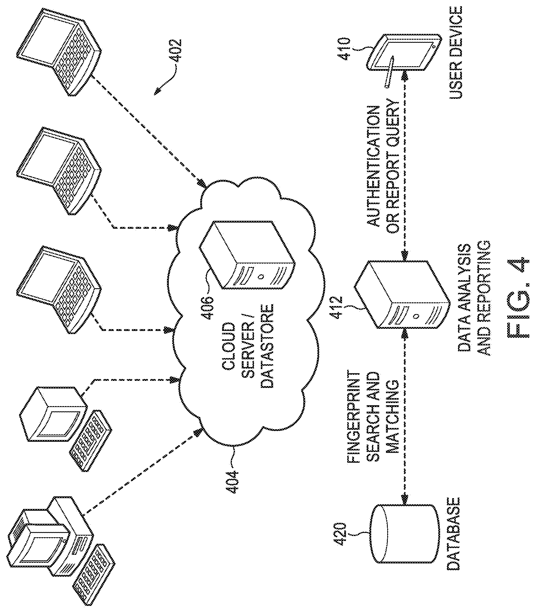
FIG. 4 is a simplified conceptual diagram illustrating use of a mobile device application to query authentication information related to an object.
FIG. 5 is a simplified flow diagram illustrating a method for tracking an object to verify its provenance.
FIG. 6 illustrates an example of authentication region and object feature definition for a U.S. passport.
DETAILED DESCRIPTION OF PREFERRED EMBODIMENTS
In this application, we use the term "scan" in a broad sense. We refer to any means for capturing an image or set of images, which may be in digital form or transformed into digital form. The images may be two dimensional, three dimensional, or be in the form of a video. Thus a "scan" may refer to an image (or digital data that defines an image) captured by a scanner, a camera, a specially-adapted sensor array such as CCD array, a microscope, a smart phone camera, a video camera, an x-ray machine, etc. Broadly, any device that can sense and capture electromagnetic radiation that has traveled through an object, or reflected off of an object, is a candidate to create a "scan" of the object. Various means to extract "fingerprints" or features from an object may be used; for example, through sound, physical structure, chemical composition, or many others. The remainder of this application will use terms like "image" but when doing so, the broader uses of this technology should be implied. In other words, alternative means to extract "fingerprints" or features from an object should be considered equivalents within the scope of this disclosure.
Authentication Regions
Because digital fingerprinting works with many different types of objects, it is necessary to define what parts of the digital images of the objects are to be used for the extraction of features for authentication purposes. This can vary widely for different classes of objects. In some cases it is the image of the entire object; in other cases it will be a specific sub-region of the image of the object. For instance, for a photograph we may want to use the digital image of the entire photograph for feature extraction. Each photograph is different, and there may be unique feature information anywhere in the photograph. So in this case, the authentication region will be the entire photograph.
Multiple regions may be used for fingerprints for several reasons, two of which are particularly important. It may be that there are several regions where significant variations take place among different similar objects that need to be distinguished while, in the same objects, there may be regions of little significance. In that case a template may be used (see below) primarily to eliminate regions of little interest.
A bank note, for example, can be authenticated if a few small arbitrary regions scattered across the surface are fingerprinted, along with recognizing the contents of a region telling the value of the bank note and one containing the bank note's serial number. In such a case the fingerprints of any region (along with sufficient additional information to determine the bank note's value and its purported identity) may be sufficient to establish the authenticity of the bill and multiple fingerprinted regions are used solely in the event that one or more regions may be absent (through, for example, tearing) when the bill is later presented for authentication. Sometimes, however, all regions of an item must be authenticated to ensure the item is both authentic and has not been altered.
A passport provides an example of feature extraction from an authentication region; see FIG. 6. On a passport, the features that we may want to use for authentication may be extracted from regions containing such specific identification information as the passport number, recipient name, and recipient photo, as illustrated in FIG. 6. In that case one may define a feature template specifying those regions whose alteration from the original would invalidate the passport, such regions including the passport holder's photo and unique personal data.
The ability to define and store the optimal authentication region for a given class of objects offers significant benefits to the user, although it is not mandatory. In many cases it is much easier to scan a limited region of an object than the entire object. For instance, in the case of an article of designer clothing, it is much easier to take a picture of the manufacturer's label than it is to take a picture of the entire garment. Further, defining such regions enable the detection of partial alteration of the object.
Once an authentication region is defined, specific applications can be created for different markets and classes of objects that can assist the user in locating and scanning the optimal authentication region. For instance, an appropriately sized location box and crosshairs can automatically appear in the viewfinder of a smartphone camera application to help the user center the camera on the authentication region, and automatically lock onto the region and take the picture when the camera is focused on the correct area. It should be noted that while some examples discussed above are essentially two-dimensional objects (passport, bank note); the present disclosure is fully applicable to three-dimensional objects as well. Scanning or image capture may be 2-D, 3-D, stereoscopic, HD etc. Image capture is not limited to the use of visible light.
In many cases, objects may have permanent labels or other identifying information attached to them. These can also be used as features for digital fingerprinting. For instance, wine may be put into a glass bottle and a label affixed to the bottle. Since it is possible for a label to be removed and reused, simply using the label itself as the authentication region is often not sufficient. In this case we may define the authentication region to include both the label and the substrate it is attached to--in this case some portion of the glass bottle. This "label and substrate" approach may be useful in defining authentication regions for many types of objects, such as consumer goods and pharmaceutical packaging. If a label has been moved from its original position, this can be an indication of tampering or counterfeiting. If the object has "tamper-proof" packaging, this may also be useful to include in the authentication region.
In some cases, we will want to use multiple authentication regions to extract unique features. For a firearm, for example, we might extract features from two different parts of the weapon. It is, of course, important that both match the original but since the two parts may both have been taken from the original weapon and affixed to a weapon of substandard quality, it may also be important to determine whether their relative positions have changed as well. In other words it may be necessary to determine that the distance (or other characteristic) between Part A's authentication region and Part B's authentication region is effectively unchanged, and only if that is accomplished can the weapon be authenticated. Specifications of this type can be stored with or as part of a digital fingerprint of the firearm.
Once a suitable digital fingerprint of an object is acquired, the object (actually some description of it) and corresponding fingerprint may be stored or "registered" in a database. For example, in some embodiments, the fingerprint may comprise one or more feature vectors. The database should be secure. In some embodiments, a unique ID also may be assigned to an object. An ID may be a convenient index in some applications. However, it is not essential, as a digital fingerprint itself can serve as a key for searching a database. In other words, by identifying an object by the unique features and characteristics of the object itself, arbitrary identifiers, labels, tags, etc. are unnecessary and, as noted, inherently unreliable.
FIG. 1 is a simplified flow diagram illustrating a method 100 for creating and storing or "registering" a digital fingerprint of an object in a database. The process in one embodiment includes acquiring a digital image of the object, block 102, as discussed above. A variety of image capture technologies and devices may be used as noted. Next, features are extracted, block 104, from the digital image data. As explained, specific features or regions of interest (authentication regions) may be selected in support of subsequent identification or authentication of the object. The extracted features are analyzed and feature vectors are extracted to form a digital fingerprint--a digital file or record associated with the original image data, indicated at block 106. The digital fingerprint preferably may be stored in a database record. Other forms of searchable digital data storage should be deemed equivalents. Further, at block 110, initialization data should be added to the database record, or associated with it in a related table. This data is associated with the physical object that was scanned. For example, a description, manufacturer, model number, serial number, contents--a wide variety of data, selected as appropriate or useful depending on the type of object.
FIG. 1B illustrates a process that includes more robust feature extraction. In this example, we again begin with acquiring digital image data, block 120. We select at least one authentication region, block 122. This may be done by analysis of the image data, analysis of related image data, by reference to a predetermined template that defines at least one authentication region, or other means. The next block 124 calls for extracting a feature vector from the selected authentication region. A feature vector may be used to represent features of a region in a more compact form. For example, a feature vector may comprise an array of color or gray scale numeric values corresponding to areas within the selected authentication region. The values may each comprise a sum, average, maximum or other function of the individual values of a corresponding group of pixels forming a sub-part of the region. In some applications, a feature vector may identify a location and shape of a distinctive aspect within a selected region. In decision 126, there may be additional feature vectors to be extracted from the same image data. In that case, the flow returns, path 130, to repeat the feature extraction step 124. This loop 130 may repeat until all desired feature vectors are collected. Optionally, there may be another authentication region to process in the same image data, see decision 132. In that case, the outer loop 133 is traversed back to block 122 for further feature extraction with respect to one or more additional authentication regions. Then some or all of the extracted feature vectors may be combined to form a digital fingerprint, block 134, which is then stored, block 136, along with related data, block 138, as mentioned above. The process returns or concludes at block 140.
A database of digital fingerprints can form the basis of a system to track and trace the object through a supply chain, distribution network, or sales channel. A track and trace system based on digital fingerprinting has unique advantages and provides unique capabilities that are not available with track and trace systems based on traditional methods.
Holograms, bar codes and serial numbers can all be duplicated with varying degrees of effort. This means that if the code or tag can be duplicated, then counterfeit objects or two objects with the same identifier can exist in the supply chain or distribution network. They can then be registered in a traditional track and trace system. All such systems rely on determining that the anti-counterfeit item (label, hologram, RFID tag) is legitimate, not that the item itself is.
Due to this weakness, track and trace systems based on traditional approaches like bar codes or serial numbers cannot prevent the resulting corruption of the system database. A counterfeit object may be mistakenly identified as genuine, and generate a false audit trail as it is tracked through the supply chain. Two or more objects with the same ID (one genuine, one or more counterfeit) may exist at the same time. Without physically examining the objects it is impossible to tell which item is genuine. Once identification is made as to which object is genuine, the false trails must be removed from the database to restore integrity. This can be extremely difficult depending on the structure of the database and the complexity of the tracking data. In some cases the objects may not have any further contact with the track and trace system (for instance if they are purchased by a consumer), and the record will never be identified as false, leaving the database permanently corrupted.
In one embodiment of the Digital Fingerprinting Track and Trace System, an item may be scanned and identified at initial manufacture. Alternatively, an item may be scanned and identified at any subsequent time or location for entry into a tracking system. This point of identification preferably is done when the item is either in the possession of its manufacturer or has been transferred by secure means to the current holder so that its legitimacy at the point of identification is adequately established.
The system then identifies the object every time it is scanned again, typically at discrete steps in manufacturing, distribution, and sale. FIG. 2 is a simplified flow diagram illustrating a method 200 for matching a digital fingerprint of a target object to a database of existing digital fingerprints. Here, we acquire image data of a "target object" i.e., the object we want to identify or authenticate by finding a match in the database, see block 202. We extract features from the target object image data, block 204, as discussed above. Then we create a new (second) digital fingerprint based on the extracted features, block 206. The next step is querying the database, block 208, for a record that matches the second digital fingerprint record. "Matching" in this context may be relative to a threshold confidence level rather than a binary decision. The requisite confidence level may vary depending on the specific application. The confidence level required may be varied dynamically responsive to the data and experience with a given system. If no "matching" record is returned, decision 210, update the second record (the digital fingerprint of the target object), block 212, to reflect that no match was found. If a match is returned, the matching record is updated to reflect the match, for example, it may be linked to the second record. The results may be returned to the user.
Typical tracking steps might include scanning at the point of manufacture, when packaged, when placed in inventory, when shipped, and at a retail point of purchase (upon arrival and again when sold), as illustrated in the tracking process 300 of FIG. 3. Each scan can be used to update a remote database.
As mentioned earlier, a "scan" may refer to an image (or digital data that defines an image) captured by a scanner, a camera, a specially-adapted sensor array such as CCD array, a microscope, a smart phone camera, a video camera, an x-ray machine, etc. Broadly, any device that can sense and capture electromagnetic radiation that has traveled through an object, or reflected off of an object, is a candidate to create a "scan" of the object. It is critical to capture at least one native feature of the object, as distinguished from a feature added to the object for identification, such as a label, bar code, RFID tag, serial number, etc.
A "native feature" in this description is not concerned with reading or recognizing meaningful content. For example, a label on a scanned object with a printed serial number may give rise to various features in fingerprint processing, some of which may become part of a digital fingerprint feature set or vector that is associated with the object. The features may refer to light and dark areas, locations, spacing, ink blobs, etc. This information may refer to the printed serial number on the label, but there is no effort to actually "read" or recognize the printed serial number (which may be bogus). Similarly, an RFID tag applied to an object may give rise to a fingerprint vector responsive to its appearance and location on the object. However, no effort is made to actually stimulate or "read" data or signals from the tag.
While the most common application of track and trace systems is in manufactured goods, the present system and methods, in various different embodiments, may be applied to any object that can be identified with a digital fingerprint and tracked. These include but are not limited to mail pieces, parcels, art, coins, currency, precious metals, gems, jewelry, apparel, mechanical parts, consumer goods, integrated circuits, firearms, pharmaceuticals and food and beverages. Tracking may consist of any sequence of actions where the object is scanned, such as each time an object is appraised, authenticated, certified, auctioned, displayed, or loaned. The system may store both positive and negative authentication transactions. In an embodiment, the system may store location information (associated with a scan or fingerprint), which provides a profile of where counterfeit goods may be encountered.
FIG. 4 is a simplified conceptual diagram illustrating use of a mobile device application to query authentication information related to an object. Here, various computing devices or terminals 402 may have access over a network, for example, the Internet 404, to cloud computing facilities/services such as a cloud server/datastore 406. For example, the devices 402 may be located at various points along a distribution chain as illustrated in FIG. 3, each location scanning an object and updating the cloud server/datastore 406.
A server 412 may be provisioned to provide tracking and/or tracing data analysis and reporting. The server 412 has access to a datastore 420 which may be used to store digital fingerprints and related data. The server can query or search the database 420 for digital fingerprint search and matching. The database 420 preferably is coupled to the cloud server 406 in some embodiments. A mobile user device 410 such as a smartphone, tablet, laptop computer or dedicated device may be configured for communications with the server 412 to request and receive a reply or authentication report for an object of interest. This architecture is simplified and in any event is merely illustrative and not intended to be limiting.
Continuous and Discrete Tracking
In some implementations, sensors may be attached to the object, and sensor data can flow back to the database in either a continuous fashion (near real time), or in discrete data transfer events. For example, data transfer may occur when an authentication event occurs. For instance, if there is a GPS chip attached to the object, data flow can start when the object is first registered in the system, and continue to flow as the object changes location. Continuous (frequent) data updates can also be buffered in local memory in a sensor attached to the item, and then downloaded the next time the object is scanned and authenticated. This provides a record of where the object has traveled (its itinerary).
As an example of the potential uses of sensor data, many products like food and beverages can degrade with exposure to certain environmental factors over the course of their storage and shipment. Examples of sensor data could include temperature, light exposure, altitude, oxygen level, or other factors, as well as location such as GPS data.
FIG. 5 is a simplified flow diagram illustrating one embodiment of a process 500 for tracking an object to verify its provenance. Here, an expected itinerary of an object (a series of locations) may be stored in a datastore if known, block 502. The methods and systems described above may be used to track the object to the next location, block 504. If the object does not arrive as expected (where and when expected according to the itinerary), the failure may be reported to a user. In an embodiment, an object that arrives later than expected may be subjected to closer matching scrutiny to ensure its identity.
The next step, block 510, is to query the database for the next valid or expected location. A unique itinerary may not be known, but a set of valid or expected locations may be known. The next actual location of the object (as determined by imaging and matching digital fingerprints) may be compared to the expected location(s) returned by the database, block 512. If that comparison indicates a departure from the expected or authorized route, decision 520, the result may be reported to a user, block 522. (A report that the object is on track may be reported as well.) Other options may be implemented such as a quantity check, block 524. The process returns or terminates at block 526.
Most existing track and trace systems are only designed to be accessed by manufacturers or their authorized distributors, and often require specialized scanners or equipment. However, the consumer also has a vested interest in determining whether the items that they are buying are authentic. In some embodiments, the present system is designed to enable anyone along the supply, distribution, or sales chain, from manufacturer to the retail consumer, to access the system and determine whether the item is authentic. A specialized scanner is not required in all cases. For example, in one embodiment a mobile phone application designed for the consumer can be used to scan an object, query the database, and determine if the object is authentic.
Finally, data collected by a digital fingerprinting system offers a variety of useful information to people along the supply, distribution and sales chain. Reports can be generated on individual items, or on sets of items. These reports can include but are not limited to the locations of items over time, audit trails, points of entry of counterfeit goods, and exposure to environmental variables over the course of an object's useful lifetime.
Tags and Bar Codes
A tag may be added to an item, a barcode to a mail piece, etc. for two reasons. First, the human may need it to know what the item is. This is the identification function. It may identify the item to a store clerk as a particular style and size of clothing of a particular manufacturer; it may tell a postal carrier where to deliver a mail piece. Second, however, are tags that are only useful for a machine. Thus a four-state bar code on a mail piece (unreadable by humans) is used to route the mail piece by machine. This entire class of machine readable tags can be replaced by the methods of this patent. The first set may still be needed for human use but are now divorced from their authentication function.
Because we are exploiting natural features and often scanning the object under variable conditions, it is highly unlikely that two different "reads" will produce the exact same fingerprint. We therefore have to introduce the ability to look up items in the database when there is a near-miss. For example, two feature vectors [0, 1, 5, 5, 6, 8] and [0, 1, 6, 5, 6, 8] are not identical but (given the proper difference metric) may be close enough to say with certainty that they are from the same item that has been seen before. This is particularly true if, otherwise, the nearest feature vector of a different item is [5, 2, 5, 8, 6, 4]. For example, a distance between vectors of n-dimensions is easily calculated, and may be used as one metric of similarity or "closeness of match" between the vectors. One may also consider the distance to the next nearest candidate.
Obviating the Chain of Custody
Many systems rely on a known "chain of custody" to verify authenticity of an object. The rules of evidence in court, for example, typically require proof of a chain of custody to demonstrate authenticity of a hair sample, weapon or other piece of physical evidence. From the time an object is collected at a crime scene, for example, it is typically bagged, tagged, and moved into a locked box or evidence room for safekeeping. Each person who removes it must attest to returning the original item unchanged. Custody of the object from the crime scene to the evidence locker to the courtroom must be accounted for as an unbroken chain. Digital fingerprinting techniques as disclosed herein can be used to obviate most of that process. Provided an original object is under the control and custody of an authorized or trusted entity at least once, and a digital fingerprint, or an image suitable for forming a digital fingerprint of the object, is acquired under such circumstances, and stored, the object is uniquely identifiable thereafter by that fingerprint for the lifetime of the object.
Because digital fingerprinting works by extracting key features of an object, it may be used to identify or authenticate objects even after a good deal of wear and tear. At any subsequent time, a suspect or "target" object can be similarly "fingerprinted" and the subsequent fingerprint compared to the stored fingerprint of the original object. If they match, authenticity is established, regardless of where or in whose custody the object may have traveled in the meantime. Returning to the crime scene example, if a digital fingerprint is acquired of a weapon taken from the crime scene, and the digital fingerprint stored, the weapon can be fingerprinted again at any subsequent time, and the digital fingerprints compared to authenticate to weapon. Custody of the weapon in the interim is no longer an issue. Likewise when a coin or piece of art is stolen our technology gives us the ability to continue the original provenance even though chain of custody has been lost (i.e. we know it is the same coin we saw before even though it has not been in our direct possession during the time between theft and recovery).
Global Vs. Regional Feature Matching
In a case where we have the original document or other object fingerprinted, our techniques allow region-by-region matching so that we can tell what (if any) regions have been changed. Thus, for example, we might get a really good overall match on a passport but none of the matches happen in the photograph--so we know the photograph probably was changed. Further, if some individual or group, say Al Qaeda, has a certain pattern or regularity to altering passports--change the photo, the date of birth and one digit of the passport number, say--then this ability to find altered regions also gives us the ability to discern the pattern of changes and thus develop a signature of the group making the changes. Thus aspects of the present technology can be applied not only to detect a forged or altered document, but to identify in some cases the source of the bogus document.
It will be obvious to those having skill in the art that many changes may be made to the details of the above-described embodiments without departing from the underlying principles of the invention. The scope of the present invention should, therefore, be determined only by the following claims.
* * * * *
References
-
ribbs.usps.gov/ncoalink/ncoalink_print.htm
-
us.generation-nt.com/online-ncoalink-processing-acknowledgement-form-paf-released-by-press-1567191.html
-
usps.com/ncsc/addressservices/moveupdate/changeaddress.htm
-
ebayinc.com/stories/news/ebay-launches-must-have-iphone-app-redlaser-30
-
iphone.appstornn.net/reviews/lifestyle/how-to-shop-savvy-with-redlaser
-
entrupy.com
-
technically/brooklyn/2016/02/11/entrupy-counterfeit-scanner
D00000
D00001
D00002
D00003
D00004
D00005
D00006
D00007
XML
uspto.report is an independent third-party trademark research tool that is not affiliated, endorsed, or sponsored by the United States Patent and Trademark Office (USPTO) or any other governmental organization. The information provided by uspto.report is based on publicly available data at the time of writing and is intended for informational purposes only.
While we strive to provide accurate and up-to-date information, we do not guarantee the accuracy, completeness, reliability, or suitability of the information displayed on this site. The use of this site is at your own risk. Any reliance you place on such information is therefore strictly at your own risk.
All official trademark data, including owner information, should be verified by visiting the official USPTO website at www.uspto.gov. This site is not intended to replace professional legal advice and should not be used as a substitute for consulting with a legal professional who is knowledgeable about trademark law.