Camera optical lens
Bian , et al. February 9, 2
U.S. patent number 10,914,920 [Application Number 15/856,982] was granted by the patent office on 2021-02-09 for camera optical lens. This patent grant is currently assigned to AAC Optics Solutions Pte. Ltd.. The grantee listed for this patent is AAC Optics Solutions Pte. Ltd.. Invention is credited to Xuqi Bian, Yanmei Wang, Lei Zhang.


| United States Patent | 10,914,920 |
| Bian , et al. | February 9, 2021 |
Camera optical lens
Abstract
The present application discloses a camera optical lens. The camera optical lens including, in an order from an object side to an image side, a first lens, a second lens, a third lens, a fourth lens, a fifth lens, a sixth lens and a seventh lens. The camera optical lens further satisfies specific conditions.
| Inventors: | Bian; Xuqi (Shenzhen, CN), Zhang; Lei (Shenzhen, CN), Wang; Yanmei (Shenzhen, CN) | ||||||||||
|---|---|---|---|---|---|---|---|---|---|---|---|
| Applicant: |
|
||||||||||
| Assignee: | AAC Optics Solutions Pte. Ltd.
(Singapore, SG) |
||||||||||
| Family ID: | 1000005351227 | ||||||||||
| Appl. No.: | 15/856,982 | ||||||||||
| Filed: | December 28, 2017 |
Prior Publication Data
| Document Identifier | Publication Date | |
|---|---|---|
| US 20190121083 A1 | Apr 25, 2019 | |
Foreign Application Priority Data
| Oct 19, 2017 [CN] | 2017 1 0975249 | |||
| Oct 19, 2017 [CN] | 2017 1 0975251 | |||
| Current U.S. Class: | 1/1 |
| Current CPC Class: | G02B 9/64 (20130101); G02B 13/0045 (20130101); G02B 1/041 (20130101) |
| Current International Class: | G02B 13/00 (20060101); G02B 1/04 (20060101); G02B 9/64 (20060101) |
| Field of Search: | ;359/708-718 |
References Cited [Referenced By]
U.S. Patent Documents
| 4264137 | April 1981 | Fujii |
| 4818081 | April 1989 | Ito |
| 5381270 | January 1995 | Cho |
| 5675440 | October 1997 | Kanamori |
| 5999338 | December 1999 | Nagahara |
| 10274701 | April 2019 | Fang |
| 10310232 | June 2019 | Zhao |
| 10310233 | June 2019 | Chen |
| 10330896 | June 2019 | Bian |
| 10451847 | October 2019 | Zhao |
| 10488621 | November 2019 | Zhao |
| 10641992 | May 2020 | Chen |
| 2015/0103414 | April 2015 | Baik |
| 2016/0085055 | March 2016 | Asami |
| 2019/0227270 | July 2019 | Zhao |
Other References
|
Lohmann, Adolf, "Scaling Laws for Lens Systems," Applied Optics, vol. 28, No. 23, pp. 4996-4998. (Year: 1989). cited by examiner. |
Primary Examiner: Pasko; Nicholas R.
Attorney, Agent or Firm: IPro, PLLC Xu; Na
Claims
What is claimed is:
1. A camera optical lens comprising, from an object side to an image side in sequence: a first lens, a second lens, a third lens, a fourth lens, a fifth lens, a sixth lens and a seventh lens; the first lens having a positive refractive power, the third lens having a negative refractive power, the sixth lens having a negative refractive power, and the seventh lens having a negative refractive power, wherein, the second lens includes a convex object side surface and a concave image side surface and the camera optical lens satisfies the following conditions: 1.05.ltoreq.f1/f.ltoreq.1.5; 1.7.ltoreq.n3.ltoreq.2.2; -2.ltoreq.f3/f4.ltoreq.2 -10.ltoreq.(R13+R14)/(R13-R14).ltoreq.10; 0.01.ltoreq.d5/TTL.ltoreq.0.1; 2.63.ltoreq.(R3+R4)/(R3-R4).ltoreq.8.78; where f: a focal length of the optical camera lens; f1: a focal length of the first lens; f3: a focal length of the third lens; f4: a focal length of the fourth lens; n3: a refractive index of the third lens; d5: a thickness on-axis of the third lens; TTL: a total distance from an object side surface of the first lens to an image surface along an optic axis; R13: a curvature radius of an object side surface of the seventh lens; R14: a curvature radius of an image side surface of the seventh lens; R3: a curvature radius of the object side surface of the second lens; R4: a curvature radius of the image side surface of the second lens.
2. The camera optical lens as described in claim 1, wherein the first lens is made of plastic material, the second lens is made of plastic material, the third lens is made of glass material, the fourth lens is made of plastic material, the fifth lens is made of plastic material, the sixth lens is made of plastic material, the seventh lens is made of plastic material.
3. The camera optical lens as described in claim 1, wherein the object side surface of the first lens is convex and the first lens further comprises a concave image side surface; the camera optical lens further satisfies the following conditions: -2.91.ltoreq.(R1+R2)/(R1-R2).ltoreq.-0.76; 0.3 mm.ltoreq.d1.ltoreq.0.97 mm; where R1: a curvature radius of the object side surface of the first lens; R2: a curvature radius of the image side surface of the first lens; d1: a thickness on-axis of the first lens.
4. The camera optical lens as described in claim 1, the camera optical lens further satisfies the following conditions: -6.26.ltoreq.f2/f.ltoreq.1.97; 0.12 mm.ltoreq.d3.ltoreq.0.41 mm; where f: the focal length of the camera optical lens; f2: a focal length of the second lens; d3: a thickness on-axis of the second lens.
5. The camera optical lens as described in claim 1, wherein the third lens has a concave object side surface and a concave image side surface; the camera optical lens further satisfies the following conditions: -63.57.ltoreq.f3/f.ltoreq.-1.09; -49.42.ltoreq.(R5+R6)/(R5-R6).ltoreq.-4.05; 0.11 mm.ltoreq.d5.ltoreq.0.51 mm; where f: the focal length of the camera optical lens; f3: a focal length of the third lens; R5: a curvature radius of the object side surface of the third lens; R6: a curvature radius of the image side surface of the third lens; d5: a thickness on-axis of the third lens.
6. The camera optical lens as described in claim 1, wherein the fourth lens includes a convex object side surface, and the camera optical lens further satisfies the following conditions: -33.45.ltoreq.f4/f.ltoreq.2057.31; -1.15.ltoreq.(R7+R8)/(R7-R8).ltoreq.493.45; 0.25 mm.ltoreq.d7.ltoreq.0.91 mm; where f: the focal length of the camera optical lens; f4: a focal length of the fourth lens; R7: a curvature radius of the object side surface of the fourth lens; R8: a curvature radius of an image side surface of the fourth lens; d7: the thickness on-axis of the fourth lens.
7. The camera optical lens as described in claim 1, wherein the fifth lens includes a convex image side surface; and the camera optical lens further satisfies the following conditions: -19.07.ltoreq.f5/f.ltoreq.0.94; 0.43.ltoreq.(R9+R10)/(R9-R10).ltoreq.1.71; 0.25 mm.ltoreq.d9.ltoreq.0.94 mm; where f: the focal length of the camera optical lens; f5: a focal length of the fifth lens; R9: a curvature radius of an object side surface of the fifth lens; R10: a curvature radius of the image side surface of the fifth lens; d9: a thickness on-axis of the fifth lens.
8. The camera optical lens as described in claim 1, wherein the sixth lens has a concave object side surface; and the camera optical lens further satisfies the following conditions: -7.73.ltoreq.f6/f.ltoreq.-1.2; -2.51.ltoreq.(R11+R12)/(R11-R12).ltoreq.-0.44; 0.13 mm.ltoreq.d11.ltoreq.0.63 mm; where f: the focal length of the camera optical lens; f6: a focal length of the sixth lens; R11: a curvature radius of the object side surface of the sixth lens; R12: a curvature radius of an image side surface of the sixth lens; d11: a thickness on-axis of the sixth lens.
9. The camera optical lens as described in claim 1, wherein the object side surface of the seventh lens is concave and the image side surface of the seventh lens is concave; the camera optical lens further satisfies the following conditions: -4.46.ltoreq.f7/f.ltoreq.-0.47; 0.14 mm.ltoreq.d13.ltoreq.0.64 mm; where f: the focal length of the camera optical lens; f7: a focal length of the seventh lens; d13: a thickness on-axis of the seventh lens.
10. The camera optical lens as described in claim 1, wherein the total distance from the object side surface of the first lens to an image surface along an optic axis TTL of the camera optical lens is less than or equal to 6.15 millimeters.
11. The camera optical lens as described in claim 1, wherein an F number of the camera optical lens is less than or equal to 1.83.
Description
CROSS-REFERENCE TO RELATED APPLICATIONS
This application claims the priority benefit of Chinese Patent Applications Ser. No. 201710975249.8 and Ser. No. 201710975251.5 filed on Oct. 19, 2017, the entire content of which is incorporated herein by reference.
FIELD OF THE PRESENT DISCLOSURE
The present disclosure relates to optical lens, in particular to a camera optical lens suitable for handheld devices such as smart phones and digital cameras and imaging devices.
DESCRIPTION OF RELATED ART
With the emergence of smart phones in recent years, the demand for miniature camera lens is increasing day by day, but the photosensitive devices of general camera lens are no other than Charge Coupled Device (CCD) or
Complementary metal-Oxide Semiconductor Sensor (CMOS sensor), and as the progress of the semiconductor manufacturing technology makes the pixel size of the photosensitive devices shrink, coupled with the current development trend of electronic products being that their functions should be better and their shape should be thin and small, miniature camera lens with good imaging quality therefor has become a mainstream in the market. In order to obtain better imaging quality, the lens that is traditionally equipped in mobile phone cameras adopts a three-piece or four-piece lens structure. And, with the development of technology and the increase of the diverse demands of users, and under this circumstances that the pixel area of photosensitive devices is shrinking steadily and the requirement of the system for the imaging quality is improving constantly, the five-piece, six-piece and seven-piece lens structure gradually appear in lens design. There is an urgent need for ultra-thin wide-angle camera lenses which have good optical characteristics and the chromatic aberration of which is fully corrected.
BRIEF DESCRIPTION OF THE DRAWINGS
Many aspects of the exemplary embodiments can be better understood with reference to the following drawings. The components in the drawing are not necessarily drawn to scale, the emphasis instead being placed upon clearly illustrating the principles of the present disclosure.
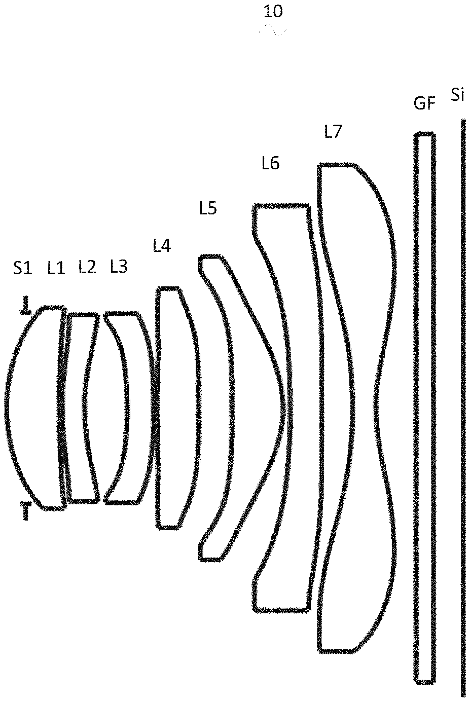
FIG. 1 is a schematic diagram of a camera optical lens in accordance with a first embodiment of the present invention;
FIG. 2 shows the axial aberration of the camera optical lens shown in FIG. 1;
FIG. 3 shows the ratio chromatic aberration of the camera optical lens shown in FIG. 1;
FIG. 4 presents a schematic diagram of the field curvature and distortion of the camera optical lens shown in FIG. 1;
FIG. 5 is a schematic diagram of a camera optical lens in accordance with a second embodiment of the present invention;
FIG. 6 presents the axial aberration of the camera optical lens shown in FIG. 5;
FIG. 7 presents the ratio chromatic aberration of the camera optical lens shown in FIG. 5;
FIG. 8 presents the field curvature and distortion of the camera optical lens shown in FIG. 5
FIG. 9 is a schematic diagram of a camera optical lens in accordance with a third embodiment of the present invention;
FIG. 10 presents the axial aberration of the camera optical lens shown in FIG. 9;
FIG. 11 presents the ratio chromatic aberration of the camera optical lens shown in FIG. 9;
FIG. 12 presents the field curvature and distortion of the camera optical lens shown in FIG. 9.
DETAILED DESCRIPTION OF THE EXEMPLARY EMBODIMENTS
The present disclosure will hereinafter be described in detail with reference to several exemplary embodiments. To make the technical problems to be solved, technical solutions and beneficial effects of the present disclosure more apparent, the present disclosure is described in further detail together with the figure and the embodiments. It should be understood the specific embodiments described hereby is only to explain the disclosure, not intended to limit the disclosure.
Embodiment 1
As referring to FIG. 1, the present invention provides a camera optical lens 10. FIG. 1 shows the camera optical lens 10 of embodiment 1 of the present invention, the camera optical lens 10 comprises 7 lenses. Specifically, from the object side to the image side, the camera optical lens 10 comprises in sequence: an aperture S1, a first lens L1, a second lens L2, a third lens L3, a fourth lens L4, a fifth lens L5, a sixth lens L6 and a seventh lens L7. Optical element like optical filter GF can be arranged between the seventh lens L7 and the image surface Si. The first lens L1 is made of plastic material, the second lens L2 is made of plastic material, the third lens L3 is made of glass material, the fourth lens L4 is made of plastic material, the fifth lens L5 is made of plastic material, the sixth lens L6 is made of plastic material, the seventh lens L7 is made of plastic material;
Here, the focal length of the whole optical camera lens 10 is defined as f, the focal length of the first lens L1 is defined as f1, the focal length of the third lens L3 is defined as f3, the focal length of the fourth lens L4 is defined as f4, the refractive index of the third lens L3 is defined as n3, the thickness on-axis of the third lens L3 is defined as d3, the total optical length of the camera optical lens is defined as TTL, the curvature radius of object side surface of the seventh lens L7 is defined as R13, the curvature radius of image side surface of the seventh lens L7 is defined as R14. The f, f1, f3, f4, n4, d7, TTL, R13 and R14 meet the following conditions: 1.05.ltoreq.f1/f.ltoreq.1.5; 1.7.ltoreq.n3.ltoreq.2.2; -2.ltoreq.f3/f4.ltoreq.2; -10.ltoreq.(R13+R14)/(R13-R14).ltoreq.10; 0.01.ltoreq.d5/TTL.ltoreq.0.1.
Condition 1.05.ltoreq.f1/f.ltoreq.1.5 fixes the positive refractive power of the first lens L1. If the lower limit of the set value is exceeded, although it benefits the ultra-thin development of lenses, but the positive refractive power of the first lens L1 will be too strong, problem like aberration is difficult to be corrected, and it is also unfavorable for wide-angle development of lens. On the contrary, if the higher limit of the set value is exceeded, the positive refractive power of the first lens L1 becomes too weak, it is then difficult to develop ultra-thin lenses. Preferably, the following condition shall be satisfied, 1.05.ltoreq.f1/f.ltoreq.1.2.
Condition 1.7.ltoreq.n3.ltoreq.2.2 fixes the refractive index of the third lens L3, a refractive power within this range benefits the development of ultra-thin lenses, and it also benefits the correction of aberration. Preferably, the following condition shall be satisfied, 1.7.ltoreq.n3.ltoreq.2.1.
Condition -2.ltoreq.f3/f4.ltoreq.2 fixes the ratio between the focal length f3 of the third lens L3 and the focal length f4 of the fourth lens L4, a ratio within this range can effectively reduce the sensitivity of lens group used in camera and further enhance the imaging quality. Preferably, the following condition shall be satisfied, -0.5.ltoreq.f3/f4.ltoreq.2.
Condition -10.ltoreq.(R13+R14)/(R13-R14).ltoreq.10 fixes the shape of the seventh lens L7, when the value is beyond this range, with the development into the direction of ultra-thin and wide-angle lenses, problem like aberration of the off-axis picture angle is difficult to be corrected. Preferably, the following condition shall be satisfied, -1.ltoreq.(R13+R14)/(R13-R14).ltoreq.1.
Condition 0.01.ltoreq.d5/TTL.ltoreq.0.1 fixes the ratio between the thickness on-axis of the third lens L3 and the total optical length TTL of the camera optical lens 10, a ratio within this range benefits the development of ultra-thin lenses. Preferably, the following condition shall be satisfied, 0.05.ltoreq.d5/TTL.ltoreq.0.075.
When the focal length of the camera optical lens 10 of the present invention, the focal length of each lens, the refractive index of the related lens, and the total optical length, the thickness on-axis and the curvature radius of the camera optical lens meet the above conditions, the camera optical lens 10 has the advantage of high performance and meets the design requirement of low TTL.
In this embodiment, the object side surface of the first lens L1 is a convex surface relative to the proximal axis, its image side surface is a concave surface relative to the proximal axis, and it has positive refractive power; the focal length of the whole camera optical lens is f, the focal length of the first lens L1 is f1, the curvature radius of the object side surface of the first lens L1 is R1, the curvature radius of the image side surface of the first lens L1 is R2 and the thickness on-axis of the first lens L1 is d1, they meet the following condition: -2.91.ltoreq.(R1+R2)/(R1-R2).ltoreq.-0.76, this condition reasonably controls the shape of the first lens, then the first lens can effectively correct the spherical aberration of the system; if the condition 0.3.ltoreq.d1.ltoreq.0.97 is satisfied it is beneficial for the realization of ultra-thin lens. Preferably, the following conditions shall be satisfied, -1.82.ltoreq.(R1+R2)/(R1-R2).ltoreq.-0.95; 0.48.ltoreq.d1.ltoreq.0.78.
In this embodiment, the object side surface of the second lens L2 is a convex surface relative to the proximal axis, its image side surface is a concave surface relative to the proximal axis, the focal length of the whole camera optical lens 10 is f, the focal length of the second lens L2 is f2, the curvature radius of the object side surface of the second lens L2 is R3, the curvature radius of image side surface of the second lens L2 is R4 and the thickness on-axis of the second lens L2 is d3, they meet the following condition: when the condition -6.26.ltoreq.f2/f.ltoreq.-1.97 is satisfied, the positive refractive power of the second lens L2 is controlled within reasonable scope, the spherical aberration caused by the first lens L1 which has positive refractive power and the field curvature of the system then can be reasonably and effectively balanced; the condition 2.63.ltoreq.(R3+R4)/(R3-R4).ltoreq.8.78 fixes the shape of the second lens L2, when value is beyond this range, with the development into the direction of ultra-thin and wide-angle lenses, problem like on-axis chromatic aberration is difficult to be corrected; if the condition 0.12.ltoreq.d3.ltoreq.0.41 is satisfied, it is beneficial for the realization of ultra-thin lenses. Preferably, the following conditions shall be satisfied, -3.91.ltoreq.f2/f.ltoreq.1.58; 4.21.ltoreq.(R3+R4)/(R3-R4).ltoreq.7.03; 0.19.ltoreq.d3.ltoreq.0.33.
In this embodiment, the object side surface of the third lens L3 is a concave surface relative to the proximal axis, its image side surface is a convex surface relative to the proximal axis, and it has negative refractive power; the focal length of the whole camera optical lens 10 is f, the focal length of the third lens L3 is f3, the curvature radius of the object side surface of the third lens L3 is R5, the curvature radius of the image side surface of the third lens L3 is R6 and the thickness on-axis of the third lens L3 is d5, they meet the condition: -63.57.ltoreq.f3/f.ltoreq.-1.09, by meeting this condition, it is helpful for the system to obtain good ability in balancing the field curvature, so that the image quality can be effectively improved; by meeting the condition -49.42.ltoreq.(R5+R6)/(R5-R6).ltoreq.-4.05 the shape of the third lens L3 can be effectively controlled, it is beneficial for the shaping of the third lens L3 and bad shaping and stress generation due to extra large curvature of surface of the third lens 13 can be avoided; when the condition 0.11.ltoreq.d5.ltoreq.0.51 is satisfied, it is beneficial for the realization of ultra-thin lenses. Preferably, the following conditions shall be satisfied, -39.73.ltoreq.f3/f.ltoreq.-1.37; -30.89.ltoreq.(R5+R6)/(R5-R6).ltoreq.-5.07; 0.18.ltoreq.d5.ltoreq.0.41.
In this embodiment, the object side surface of the fourth lens L4 is a convex surface relative to the proximal axis, the focal length of the whole camera optical lens 10 is f, the focal length of the fourth lens L4 is f4, the curvature radius of the object side surface of the fourth lens L4 is R7, the curvature radius of the image side surface of the fourth lens L4 is R8 and the thickness on-axis of the fourth lens L4 is d7, they meet the condition: -33.45.ltoreq.f4/f.ltoreq.2057.31, the appropriate distribution of refractive power makes it possible that the system has better imaging quality and lower sensitivity; the condition -1.15.ltoreq.(R7+R8)/(R7-R8).ltoreq.493.45 fixes the shape of the fourth lens L4, when beyond this range, with the development into the direction of ultra-thin and wide-angle lens, the problem like chromatic aberration is difficult to be corrected; when the condition 0.25.ltoreq.d7.ltoreq.0.91 is satisfied, it is beneficial for realization of ultra-thin lenses. Preferably, the following conditions shall be satisfied, -20.91.ltoreq.f4/f.ltoreq.1645.85; -0.72.ltoreq.(R7+R8)/(R7-R8).ltoreq.394.76; 0.41.ltoreq.d7.ltoreq.0.73.
In this embodiment, the image side surface of the fifth lens L5 is a convex surface relative to the proximal axis, the focal length of the whole camera optical lens 10 is f, the focal length of the fifth lens L5 is f5, the curvature radius of the object side surface of the fifth lens L5 is R9, the curvature radius of the image side surface of the fifth lens L5 is R10 and the thickness on-axis of the fifth lens L5 is d9, they meet the condition: -19.07.ltoreq.f5/f.ltoreq.0.94, the limitation on the fifth lens L5 can effectively make the light angle of the camera lens flat and the tolerance sensitivity reduces; the condition 0.43.ltoreq.(R9+R10)/(R9-R10).ltoreq.1.71 fixes the shape of the fifth lens L5, when beyond this range, with the development into the direction of ultra-thin and wide-angle lens, the problem like off-axis chromatic aberration is difficult to be corrected; when the condition 0.25.ltoreq.d9.ltoreq.0.94 is satisfied, it is beneficial for the realization of ultra-thin lens. Preferably, the following conditions shall be satisfied, -11.92.ltoreq.f5/f.ltoreq.0.76; 0.69.ltoreq.(R9+R10)/(R9-R10).ltoreq.1.36; 0.4.ltoreq.d9.ltoreq.0.75.
In this embodiment, the object side surface of the sixth lens L6 is a concave surface relative to the proximal axis, and it has negative refractive power; the focal length of the whole camera optical lens 10 is f, the focal length of the sixth lens L6 is f6, the curvature radius of the object side surface of the sixth lens L6 is R11, the curvature radius of the image side surface of the sixth lens L6 is R12 and the thickness on-axis of the sixth lens L6 is d11, they meet the condition: -7.73.ltoreq.f6/f.ltoreq.-1.2, the appropriate distribution of refractive power makes it possible that the system has better imaging quality and lower sensitivity; the condition -2.51.ltoreq.(R11+R12)/(R11-R12).ltoreq.-0.44 fixes the shape of the sixth lens L6, when beyond this range, with the development into the direction of ultra-thin and wide-angle lenses, the problem like off-axis chromatic aberration is difficult to be corrected; when the condition 0.13.ltoreq.d11.ltoreq.0.63, is satisfied, it is beneficial for the realization of ultra-thin lens. Preferably, the following conditions shall be satisfied, -4.83.ltoreq.f6/f.ltoreq.-1.5; -1.57.ltoreq.(R11+R12)/(R11-R12).ltoreq.-0.55; 0.2.ltoreq.d11.ltoreq.0.5.
In this embodiment, the object side surface of the seventh lens L7 is a concave surface relative to the proximal axis, its image side surface is a concave surface relative to the proximal axis, and it has negative refractive power; the focal length of the whole camera optical lens 10 is f, the focal length of the seventh lens L7 is f7 and the thickness on-axis of the seventh lens L7 is d13, they meet the conditions -4.46.ltoreq.f7/f.ltoreq.-0.47, appropriate distribution of refractive power makes it possible that the system has better imaging quality and lower sensitivity; when the condition 0.14.ltoreq.d13.ltoreq.0.64 is satisfied, it is beneficial for the realization of ultra-thin lens. Preferably, the following conditions shall be satisfied, -2.79.ltoreq.f7/f.ltoreq.-0.58; 0.22.ltoreq.d13.ltoreq.0.51.
In this embodiment, the total optical length TTL of the camera optical lens 10 is less than or equal to 6.15 mm, it is beneficial for the realization of ultra-thin lenses. Preferably, the total optical length TTL of the camera optical lens 10 is less than or equal to 5.87.
In this embodiment, the aperture F number of the camera optical lens 10 is less than or equal to 1.83. A large aperture has better imaging performance. Preferably, the aperture F number of the camera optical lens 10 is less than or equal to 1.80.
With such design, the total optical length TTL of the whole camera optical lens 10 can be made as short as possible, thus the miniaturization characteristics can be maintained.
In the following, an example will be used to describe the camera optical lens 10 of the present invention. The symbols recorded in each example are as follows. The unit of distance, radius and center thickness is mm.
TTL: Optical length (the distance on-axis from the object side surface to the image side surface of the first lens L1).
Preferably, inflexion points and/or arrest points can also be arranged on the object side surface and/or image side surface of the lens, so that the demand for high quality imaging can be satisfied, the description below can be referred for specific implementable scheme.
The design information of the camera optical lens 10 in the first embodiment of the present invention is shown in the following, the unit of the focal length, distance, radius and center thickness is mm.
The design information of the camera optical lens 10 in the first embodiment of the present invention is shown in the tables 1 and 2.
TABLE-US-00001 TABLE 1 R d nd vd S1 .infin. d0 = -0.232 R1 2.114 d1 = 0.644 nd1 1.5462 v1 55.95 R2 11.429 d2 = 0.036 R3 3.594 d3 = 0.272 nd2 1.6580 v2 21.49 R4 2.527 d4 = 0.524 R5 -4.942 d5 = 0.326 nd3 1.7257 v3 21.50 R6 -6.889 d6 = 0.042 R7 12.170 d7 = 0.509 nd4 1.5462 v4 55.95 R8 -45.347 d8 = 0.407 R9 -21.651 d9 = 0.625 nd5 1.5462 v5 55.95 R10 -1.388 d10 = 0.087 R11 -10.306 d11 = 0.389 nd6 1.6417 v6 23.97 R12 -3103.794 d12 = 0.376 R13 -5.064 d13 = 0.281 nd7 1.5462 v7 55.95 R14 2.067 d14 = 0.500 R15 .infin. d15 = 0.210 ndg 1.5187 vg 64.17 R16 .infin. d16 = 0.363
In which, the meaning of the various symbols is as follows.
S1: Aperture;
R: The curvature radius of the optical surface, the central curvature radius in case of lens;
R1: The curvature radius of the object side surface of the first lens L1;
R2: The curvature radius of the image side surface of the first lens L1;
R3: The curvature radius of the object side surface of the second lens L2;
R4: The curvature radius of the image side surface of the second lens L2;
R5: The curvature radius of the object side surface of the third lens L3;
R6: The curvature radius of the image side surface of the third lens L3;
R7: The curvature radius of the object side surface of the fourth lens L4;
R8: The curvature radius of the image side surface of the fourth lens L4;
R9: The curvature radius of the object side surface of the fifth lens L5;
R10: The curvature radius of the image side surface of the fifth lens L5;
R11: The curvature radius of the object side surface of the sixth lens L6;
R12: The curvature radius of the image side surface of the sixth lens L6;
R13: The curvature radius of the object side surface of the seventh lens L7;
R14: The curvature radius of the image side surface of the seventh lens L7;
R15: The curvature radius of the object side surface of the optical filter GF;
R16: The curvature radius of the image side surface of the optical filter GF;
d: The thickness on-axis of the lens and the distance on-axis between the lens;
d0: The distance on-axis from aperture S1 to the object side surface of the first lens L1;
d1: The thickness on-axis of the first lens L1;
d2: The distance on-axis from the image side surface of the first lens L1 to the object side surface of the second lens L2;
d3: The thickness on-axis of the second lens L2;
d4: The distance on-axis from the image side surface of the second lens L2 to the object side surface of the third lens L3;
d5: The thickness on-axis of the third lens L3;
d6: The distance on-axis from the image side surface of the third lens L3 to the object side surface of the fourth lens L4;
d7: The thickness on-axis of the fourth lens L4;
d8: The distance on-axis from the image side surface of the fourth lens L4 to the object side surface of the fifth lens L5;
d9: The thickness on-axis of the fifth lens L5;
d10: The distance on-axis from the image side surface of the fifth lens L5 to the object side surface of the sixth lens L6;
d11: The thickness on-axis of the sixth lens L6;
d12: The distance on-axis from the image side surface of the sixth lens L6 to the object side surface of the seventh lens L7;
d13: The thickness on-axis of the seventh lens L7;
d14: The distance on-axis from the image side surface of the seventh lens L7 to the object side surface of the optical filter GF;
d15: The thickness on-axis of the optical filter GF;
d16: The distance on-axis from the image side surface to the image surface of the optical filter GF;
nd: The refractive index of the d line;
nd1: The refractive index of the d line of the first lens L1;
nd2: The refractive index of the d line of the second lens L2;
nd3: The refractive index of the d line of the third lens L3;
nd4: The refractive index of the d line of the fourth lens L4;
nd5: The refractive index of the d line of the fifth lens L5;
nd6: The refractive index of the d line of the sixth lens L6;
nd7: The refractive index of the d line of the seventh lens L7;
ndg: The refractive index of the d line of the optical filter GF;
vd: The abbe number;
v1: The abbe number of the first lens L1;
v2: The abbe number of the second lens L2;
v3: The abbe number of the third lens L3;
v4: The abbe number of the fourth lens L4;
v5: The abbe number of the fifth lens L5;
v6: The abbe number of the sixth lens L6;
v7: The abbe number of the seventh lens L7;
vg: The abbe number of the optical filter GF;
Table 2 shows the aspherical surface data of the camera optical lens 10 in the embodiment 1 of the present invention.
TABLE-US-00002 TABLE 2 Conic Index Aspheric Surface Indexes k A4 A6 A8 A10 A12 A14 A16 R1 -6.58E-02 1.16E-02 2.07E-03 9.03E-04 1.81E-03 2.23E-04 -7.45E-04 7.76E-- 04 R2 -9.90E+01 -3.37E-03 1.52E-03 3.89E-03 1.75E-03 -5.58E-04 -1.88E-04 -3.4- 9E-04 R3 -1.27E+01 -2.69E-02 -1.09E-02 2.16E-03 -1.09E-03 4.99E-03 1.81E-03 -4.2- 5E-03 R4 -5.64E+00 -6.51E-03 -1.79E-02 -5.06E-03 -2.92E-03 4.94E-03 4.65E-03 -3.- 35E-03 R5 1.39E+01 -3.05E-02 -4.04E-02 -2.53E-02 9.50E-03 9.91E-03 -6.18E-03 7.01- E-03 R6 2.42E+01 -1.92E-02 -3.83E-02 6.60E-03 8.35E-03 3.89E-04 -1.54E-03 9.92E- -04 R7 2.91E+01 -5.17E-02 1.26E-02 1.49E-03 6.35E-05 6.35E-05 -2.83E-05 1.83E-- 05 R8 -9.90E+01 -6.99E-02 3.19E-03 2.14E-03 -4.63E-04 -3.19E-04 5.67E-05 1.51- E-04 R9 -3.81E+01 -3.87E-02 -1.27E-04 -1.62E-04 -1.15E-03 1.43E-04 9.40E-05 -8.- 27E-07 R10 -3.62E+00 -3.42E-02 1.77E-02 -1.07E-03 -4.29E-04 -2.34E-05 1.19E-05 -9- .59E-07 R11 -6.39E+00 -1.37E-02 9.40E-06 3.65E-04 2.88E-06 -3.40E-05 1.20E-07 9.99- E-07 R12 9.74E+01 -9.00E-03 1.17E-04 7.44E-05 7.89E-06 -7.06E-07 -1.03E-07 2.44- E-08 R13 1.14E+00 -3.51E-03 2.33E-03 4.15E-05 -1.38E-05 -1.09E-06 -9.69E-09 1.3- 2E-08 R14 -1.06E+01 -2.59E-02 4.20E-03 -5.18E-04 2.00E-05 1.12E-06 1.63E-08 -1.1- 4E-08
Where, K is a conic index, A4, A6, A8, A10, A12, A14, a16 are aspheric surface indexes.
IH: Image height y=(x.sup.2/R)/[1+{1-(k+1)(x.sup.2/R.sup.2)}.sup.1/2]+A4x.sup.4+A6x.sup.6+- A8x.sup.8+A10x.sup.10+A12x.sup.12+A14x.sup.14+A16x.sup.16 (1)
For convenience, the aspheric surface of each lens surface uses the aspheric surfaces shown in the above condition (1). However, the present invention is not limited to the aspherical polynomials form shown in the condition (1).
Table 3 and table 4 show the inflexion points and the arrest point design data of the camera optical lens 10 lens in embodiment 1 of the present invention. In which, R1 and R2 represent respectively the object side surface and image side surface of the first lens L1, R3 and R4 represent respectively the object side surface and image side surface of the second lens L2, R5 and R6 represent respectively the object side surface and image side surface of the third lens L3, R7 and R8 represent respectively the object side surface and image side surface of the fourth lens L4, R9 and R10 represent respectively the object side surface and image side surface of the fifth lens L5, R11 and R12 represent respectively the object side surface and image side surface of the sixth lens L6, R13 and R14 represent respectively the object side surface and image side surface of the seventh lens L7. The data in the column named "inflexion point position" are the vertical distances from the inflexion points arranged on each lens surface to the optic axis of the camera optical lens 10. The data in the column named "arrest point position" are the vertical distances from the arrest points arranged on each lens surface to the optic axis of the camera optical lens 10.
TABLE-US-00003 TABLE 3 Inflexion point Inflexion point Inflexion point number position 1 position 2 R1 R2 1 1.145 R3 1 0.645 R4 1 0.755 R5 1 1.055 R6 1 1.125 R7 2 0.395 0.735 R8 1 1.295 R9 1 1.555 R10 2 1.185 1.525 R11 1 1.995 R12 1 2.005 R13 1 1.545 R14 1 0.755
TABLE-US-00004 TABLE 4 Arrest point Arrest point Arrest point number position 1 position 2 R1 R2 R3 1 1.065 R4 R5 R6 R7 2 1.035 1.205 R8 R9 R10 R11 R12 1 2.415 R13 1 2.665 R14 1 1.715
FIG. 2 and FIG. 3 show the axial aberration and ratio chromatic aberration schematic diagrams after light with a wavelength of 435.8 nm, 486.1 nm, 546.1 nm, 587.6 nm and 656.3 nm passes the camera optical lens 10 in the first embodiment. FIG. 4 shows the field curvature and distortion schematic diagrams after light with a wavelength of 546.1 nm passes the camera optical lens 10 in the first embodiment, the field curvature S in FIG. 4 is a field curvature in the sagittal direction, T is a field curvature in the meridian direction.
Table 13 shows the various values of the embodiments 1, 2, 3 and the values corresponding with the parameters which are already specified in the condition expressions.
As shown in Table 13, the first embodiment meets the various condition expressions.
In this embodiment, the pupil entering diameter of the camera optical lens is 2.335 mm, the full vision field image height is 3.475 mm, the vision field angle in the diagonal direction is 79.09.degree., it has wide-angle and is ultra-thin, its on-axis and off-axis chromatic aberrations are fully corrected, and it has excellent optical characteristics.
Embodiment 2
Embodiment 2 is basically the same as embodiment 1, the meaning of its symbols is the same as that of embodiment 1, in the following, only the differences are listed.
Table 5 and table 6 show the design data of the camera optical lens 20 in embodiment 2 of the present invention.
TABLE-US-00005 TABLE 5 R d nd vd S1 .infin. d0 = -0.232 R1 2.051 d1 = 0.648 nd1 1.5462 v1 55.95 R2 12.467 d2 = 0.039 R3 3.646 d3 = 0.273 nd2 1.6580 v2 21.49 R4 2.481 d4 = 0.550 R5 -5.954 d5 = 0.341 nd3 1.7270 v3 21.50 R6 -7.600 d6 = 0.046 R7 16.399 d7 = 0.524 nd4 1.5462 v4 55.95 R8 16.300 d8 = 0.288 R9 -67.973 d9 = 0.535 nd5 1.5462 v5 55.95 R10 -1.331 d10 = 0.072 R11 -10.210 d11 = 0.418 nd6 1.6417 v6 23.97 R12 49.431 d12 = 0.288 R13 -8.01382268 d13 = 0.425 nd7 1.5462 v7 55.95 R14 2.013930329 d14 = 0.500 R15 .infin. d15 = 0.210 ndg 1.5187 vg 64.17 R16 .infin. d16 = 0.419
Table 6 shows the aspherical surface data of each lens of the camera optical lens 20 in embodiment 2 of the present invention.
TABLE-US-00006 TABLE 6 Conic Index Aspherical Surface Index k A4 A6 A8 A10 A12 A14 A16 R1 -2.4616E-01 8.7134E-03 -3.4228E-04 4.0745E-04 1.0503E-03 4.4668E-05 -6.- 7134E-04 1.2377E-04 R2 -9.9009E+01 -2.1242E-02 7.6518E-03 3.5581E-03 -7.7349E-04 -2.4153E-03 -- 7.5647E-04 7.5340E-04 R3 -1.3799E+01 -2.6252E-02 -4.7358E-03 8.9054E-03 -1.9476E-03 1.5600E-04 -- 2.4088E-04 -3.3015E-04 R4 -4.3775E+00 -3.1328E-03 -1.5017E-02 1.6588E-03 -4.1349E-04 -1.1769E-03 - -2.3299E-03 2.5364E-03 R5 1.4506E+01 -3.7436E-02 -3.7589E-02 -3.1936E-02 7.8982E-03 1.1386E-02 -5- .2191E-03 7.1518E-03 R6 2.4457E+01 -1.8072E-02 -3.9807E-02 5.5249E-03 7.2072E-03 1.1717E-04 -1.- 2119E-03 1.5339E-03 R7 9.1144E+01 -4.7604E-02 1.6164E-02 2.2585E-03 -6.6153E-04 -5.2126E-04 -1- .8412E-04 2.6209E-05 R8 -1.8622E+01 -7.3328E-02 3.1761E-03 2.1309E-03 -4.1243E-04 -2.3675E-04 7- .3486E-06 -2.7317E-05 R9 9.9002E+01 -4.3440E-02 -1.9856E-03 -5.5801E-04 -1.1700E-03 1.4901E-04 9- .2817E-05 1.3514E-06 R10 -3.3657E+00 -3.2812E-02 1.8657E-02 -7.8995E-04 -3.8682E-04 -2.1754E-05- 9.2905E-06 -2.2958E-06 R11 -4.4274E+01 -1.2014E-02 1.3965E-04 3.5312E-04 -3.0603E-06 -3.5309E-05 - 3.3870E-08 1.0788E-06 R12 7.4279E+01 -8.8375E-03 1.4984E-04 7.9187E-05 8.3979E-06 -6.7669E-07 -1- .1314E-07 1.8657E-08 R13 2.0426E+00 -4.2208E-03 2.2636E-03 3.5179E-05 -1.4531E-05 -1.1847E-06 -- 1.6576E-08 1.2327E-08 R14 -8.9700E+00 -2.4422E-02 4.3317E-03 -5.1049E-04 2.0447E-05 1.1349E-06 1- .7312E-08 -1.1326E-08
Table 7 and table 8 show the inflexion points and the arrest point design data of the camera optical lens 20 lens in embodiment 2 of the present invention.
TABLE-US-00007 TABLE 7 Inflexion point Inflexion point Inflexion point Inflexion point number position 1 position 2 position 3 R1 R2 1 0.635 R3 1 0.735 R4 2 1.085 R5 1 1.045 R6 1 1.085 R7 3 0.365 1.005 1.085 R8 1 0.065 R9 R10 2 1.095 1.625 R11 1 1.985 R12 2 0.455 1.945 R13 2 1.385 2.525 R14 1 0.815
TABLE-US-00008 TABLE 8 Arrest point Arrest point Arrest point number position 1 position 2 R1 R2 1 1.085 R3 R4 R5 R6 R7 3 0.685 R8 1 0.455 R9 R10 R11 R12 2 1.945 2.355 R13 1 2.105 R14 1 1.965
FIG. 6 and FIG. 7 show the axial aberration and ratio chromatic aberration schematic diagrams after light with a wavelength of 435.8 nm, 486.1 nm, 546.1 nm, 587.6 nm, 656.3 nm passes the camera optical lens 20 in the second embodiment. FIG. 8 shows the field curvature and distortion schematic diagrams after light with a wavelength of 546.1 nm passes the camera optical lens 20 in the second embodiment.
As shown in Table 13, the second embodiment meets the various conditions.
In this embodiment, the pupil entering diameter of the camera optical lens is 2.336 mm, the full vision field image height is 3.475 mm, the vision field angle in the diagonal direction is 79.09.degree., it has wide-angle and is ultra-thin, its on-axis and off-axis chromatic aberrations are fully corrected, and it has excellent optical characteristics.
Embodiment 3
Embodiment 3 is basically the same as embodiment 1, the meaning of its symbols is the same as that of embodiment 1, in the following, only the differences are listed.
The design information of the camera optical lens 30 in the third first embodiment of the present invention is shown in the tables 9 and 10.
TABLE-US-00009 TABLE 9 R d nd vd S1 .infin. d0 = -0.232 R1 2.528 d1 = 0.595 nd1 1.5462 v1 55.95 R2 39.804 d2 = 0.039 R3 2.277 d3 = 0.243 nd2 1.6580 v2 21.49 R4 1.612 d4 = 0.606 R5 -8.740 d5 = 0.221 nd3 2.0000 v3 21.50 R6 -9.477 d6 = 0.138 R7 12.112 d7 = 0.610 nd4 1.5462 v4 55.95 R8 9.020 d8 = 0.198 R9 20.412 d9 = 0.502 nd5 1.5462 v5 55.95 R10 -1.523 d10 = 0.649 R11 -4.238 d11 = 0.252 nd6 1.6417 v6 23.97 R12 -37.483 d12 = 0.373 R13 -3.064 d13 = 0.286 nd7 1.5462 v7 55.95 R14 9.061 d14 = 0.500 R15 .infin. d15 = 0.210 ndg 1.5187 vg 64.17 R16 .infin. d16 = 0.178
Table 10 shows the aspherical surface data of each lens of the camera optical lens 30 in embodiment 3 of the present invention.
TABLE-US-00010 TABLE 10 Conic Index Aspherical Surface Index k A4 A6 A8 A10 A12 A14 A16 R1 3.8514E-01 1.6752E-02 -1.3794E-02 3.8728E-02 -4.2829E-02 2.2903E-02 -2.- 4770E-03 -1.0936E-03 R2 9.9006E+01 -1.3158E-02 4.4524E-02 -3.2026E-02 -4.8542E-03 7.8022E-03 1.- 0275E-02 -7.9867E-03 R3 -6.6276E+00 -7.4407E-02 -5.0585E-03 5.3682E-02 -7.3883E-02 2.0058E-03 5- .8889E-02 -3.0282E-02 R4 -4.6881E+00 -1.4354E-02 -5.7898E-02 7.9738E-02 -5.7887E-02 4.1464E-03 2- .3510E-02 -3.6852E-03 R5 -1.7329E+01 -3.4337E-02 -3.6924E-02 -4.1227E-02 9.9216E-03 1.4438E-02 -- 5.7469E-03 2.6960E-03 R6 1.0158E+01 -8.4726E-03 -4.5837E-02 -3.4739E-03 4.5538E-03 2.3901E-03 1.- 5152E-03 -1.8285E-03 R7 5.7773E+01 -3.3619E-02 2.3249E-02 2.2730E-03 -3.4739E-03 -2.8820E-04 9.- 3361E-04 -2.2105E-04 R8 -4.2617E+01 -8.3554E-02 -2.2152E-03 5.3402E-05 -4.5348E-04 3.0375E-04 4- .6695E-04 -5.6533E-06 R9 -9.9001E+01 -5.0227E-02 -8.9263E-03 -1.7376E-03 -1.3588E-03 3.1612E-04 - 1.6503E-04 7.0158E-05 R10 -3.4682E+00 -4.3778E-02 1.8485E-02 -1.9649E-04 -3.4735E-06 7.2696E-05 - 2.1754E-05 -1.8098E-05 R11 -1.7430E+01 -1.1851E-02 -1.6618E-03 2.3643E-04 2.0728E-05 -2.2386E-05 - 5.1462E-07 7.4375E-08 R12 9.9003E+01 -1.4655E-02 9.0132E-05 7.9070E-05 9.6680E-06 -3.5653E-07 -6- .5423E-08 2.2150E-09 R13 4.2240E-01 -6.3440E-04 3.0720E-03 1.2326E-04 -5.9641E-06 -6.7124E-07 -- 1.9676E-09 2.5400E-08 R14 1.4836E+00 -2.4815E-02 3.9627E-03 -5.1046E-04 2.1289E-05 1.1792E-06 2.- 4512E-08 -1.5888E-08
Table 11 and table 12 show the inflexion points and the arrest point design data of the camera optical lens 30 lens in embodiment 3 of the present invention.
TABLE-US-00011 TABLE 11 Inflexion point Inflexion point Inflexion point number position 1 position 2 R1 R2 1 0.995 R3 1 0.585 R4 0 R5 R6 R7 R8 2 0.325 1.285 R9 2 0.285 1.405 R10 1 1.115 R11 R12 1 2.285 R13 2 1.615 2.285 R14
TABLE-US-00012 TABLE 12 Arrest point number Arrest point position 1 R1 R2 1 1.105 R3 1 1.035 R4 R5 R6 R7 R8 1 0.555 R9 1 0.475 R10 R11 R12 R13 R14
FIG. 10 and FIG. 11 show the axial aberration and ratio chromatic aberration schematic diagrams after light with a wavelength of 435.8 nm, 486.1 nm, 546.1 nm, 587.6 nm and 656.3 passes the camera optical lens 30 in the first embodiment. FIG. 12 shows the field curvature and distortion schematic diagrams after light with a wavelength of 546.1 nm passes the camera optical lens 30 in the third embodiment.
The following table 13, in accordance with the above condition expressions, lists the values in this embodiment corresponding with each condition expression. Apparently, the camera optical system of this embodiment meets the above condition expressions.
In this embodiment, the pupil entering diameter of the camera optical lens is 2.335 mm, the full vision field image height is 3.475 mm, the vision field angle in the diagonal direction is 79.10.degree., it has wide-angle and is ultra-thin, its on-axis and off-axis chromatic aberrations are fully corrected, and it has excellent optical characteristics.
TABLE-US-00013 TABLE 13 Embodiment Embodiment Embodiment 1 2 3 f 4.157 4.159 4.157 f1 4.635 4.397 4.914 f2 5.462 -13.017 -9.828 f3 -6.810 -41.414 -132.119 f4 22.281 5703.607 -69.526 f5 -39.636 2.478 2.616 f6 -16.060 -13.151 -7.468 f7 -9.270 -2.903 -4.157 f3/f4 -0.306 -0.007 1.900 (R1 + R2)/(R1 - R2) -1.454 -1.394 -1.136 (R3 + R4)/(R3 - R4) 5.739 5.262 5.854 (R5 + R6)/(R5 - R6) -6.079 -8.232 -24.710 (R7 + R8)/(R7 - R8) -0.577 328.966 6.834 (R9 + R10)/(R9 - R10) 1.137 1.040 0.861 (R11 + R12)/(R11 - R12) -1.007 -0.658 -1.255 (R13 + R14)/(R13 - R14) 0.420 0.598 -0.495 f1/f 1.115 1.057 1.182 f2/f 1.314 -3.130 -2.364 f3/f -1.638 -9.959 -31.785 f4/f 5.360 1371.538 -16.726 f5/f -9.536 0.596 0.629 f6/f -3.864 -3.162 -1.797 f7/f -2.230 -0.698 -1.000 d1 0.644 0.648 0.595 d3 0.272 0.273 0.243 d5 0.326 0.341 0.221 d7 0.509 0.524 0.610 d9 0.625 0.535 0.502 d11 0.389 0.418 0.252 d13 0.281 0.425 0.286 Fno 1.780 1.780 1.780 TTL 5.590 4.947 5.212 d5/TTL 0.058 0.069 0.042 n1 1.5462 1.5462 1.5462 n2 1.6580 1.6580 1.6580 n3 1.7257 1.7270 2.0000 n4 1.5462 1.5462 1.5462 n5 1.5462 1.5462 1.5462 n6 1.6417 1.6417 1.6417 n7 1.5462 1.5462 1.5462
It is to be understood, however, that even though numerous characteristics and advantages of the present exemplary embodiments have been set forth in the foregoing description, together with details of the structures and functions of the embodiments, the disclosure is illustrative only, and changes may be made in detail, especially in matters of shape, size, and arrangement of parts within the principles of the invention to the full extent indicated by the broad general meaning of the terms where the appended claims are expressed.
* * * * *
D00000
D00001
D00002
D00003
D00004
D00005
D00006
D00007
D00008
D00009
XML
uspto.report is an independent third-party trademark research tool that is not affiliated, endorsed, or sponsored by the United States Patent and Trademark Office (USPTO) or any other governmental organization. The information provided by uspto.report is based on publicly available data at the time of writing and is intended for informational purposes only.
While we strive to provide accurate and up-to-date information, we do not guarantee the accuracy, completeness, reliability, or suitability of the information displayed on this site. The use of this site is at your own risk. Any reliance you place on such information is therefore strictly at your own risk.
All official trademark data, including owner information, should be verified by visiting the official USPTO website at www.uspto.gov. This site is not intended to replace professional legal advice and should not be used as a substitute for consulting with a legal professional who is knowledgeable about trademark law.