System and method for analyzing athletic activity
Rice , et al. February 9, 2
U.S. patent number 10,914,645 [Application Number 15/991,638] was granted by the patent office on 2021-02-09 for system and method for analyzing athletic activity. This patent grant is currently assigned to NIKE, Inc.. The grantee listed for this patent is NIKE, Inc.. Invention is credited to Jordan M. Rice, Steven H. Walker.


View All Diagrams
| United States Patent | 10,914,645 |
| Rice , et al. | February 9, 2021 |
System and method for analyzing athletic activity
Abstract
Various sensor systems are described herein, including inserts having sensors thereon, which are configured to be received in an article of footwear. The inserts may be connected to a sole member of the footwear, or may function as a sole member. The sensors may be bonded to an outer surface of the insert in some configurations. The system may also include an electronic module that is overmolded into the sole structure and includes a connector for external access.
| Inventors: | Rice; Jordan M. (Portland, OR), Walker; Steven H. (Camas, WA) | ||||||||||
|---|---|---|---|---|---|---|---|---|---|---|---|
| Applicant: |
|
||||||||||
| Assignee: | NIKE, Inc. (Beaverton,
OR) |
||||||||||
| Family ID: | 1000005350968 | ||||||||||
| Appl. No.: | 15/991,638 | ||||||||||
| Filed: | May 29, 2018 |
Prior Publication Data
| Document Identifier | Publication Date | |
|---|---|---|
| US 20180274996 A1 | Sep 27, 2018 | |
Related U.S. Patent Documents
| Application Number | Filing Date | Patent Number | Issue Date | ||
|---|---|---|---|---|---|
| 14088016 | Nov 22, 2013 | 10024740 | |||
| 61801235 | Mar 15, 2013 | ||||
| Current U.S. Class: | 1/1 |
| Current CPC Class: | G01L 1/2206 (20130101); A43B 13/12 (20130101); G01L 1/16 (20130101); A43C 19/00 (20130101); H01L 41/04 (20130101); G01L 1/18 (20130101); A43B 13/14 (20130101); A43B 3/0005 (20130101); A63B 24/0062 (20130101) |
| Current International Class: | G01L 1/22 (20060101); A43B 13/14 (20060101); A43B 13/12 (20060101); G01L 1/16 (20060101); G01L 1/18 (20060101); H01L 41/04 (20060101); A43B 3/00 (20060101); A63B 24/00 (20060101); A43C 19/00 (20060101) |
References Cited [Referenced By]
U.S. Patent Documents
| 4578769 | March 1986 | Frederick |
| 4647918 | March 1987 | Goforth |
| 4745930 | May 1988 | Confer |
| 4814661 | March 1989 | Ratzlaff et al. |
| 4862743 | September 1989 | Seitz |
| 4866412 | September 1989 | Rzepczynski |
| 5010774 | April 1991 | Kikuo et al. |
| 5033291 | July 1991 | Podoloff et al. |
| 5154960 | October 1992 | Mucci et al. |
| 5253656 | October 1993 | Rincoe et al. |
| 5303131 | April 1994 | Wu |
| 5373651 | December 1994 | Wood |
| 5374821 | December 1994 | Muhs et al. |
| 5408873 | April 1995 | Schmidt et al. |
| 5471405 | November 1995 | Marsh |
| 5500635 | March 1996 | Mott |
| 5588227 | December 1996 | Goldston et al. |
| 5644858 | July 1997 | Bemis |
| 5655316 | August 1997 | Huang |
| 5714706 | February 1998 | Nakada et al. |
| 5813406 | September 1998 | Kramer et al. |
| 5889464 | March 1999 | Huang |
| 5929332 | July 1999 | Brown |
| 6017128 | January 2000 | Goldston et al. |
| 6122846 | September 2000 | Gray et al. |
| 6155120 | December 2000 | Taylor |
| 6174294 | January 2001 | Crabb et al. |
| 6195921 | March 2001 | Truong |
| 6330757 | December 2001 | Russell |
| 6360597 | March 2002 | Hubbard, Jr. |
| 6539336 | March 2003 | Vock et al. |
| 6578291 | June 2003 | Hirsch et al. |
| 6739200 | May 2004 | Norton |
| 7277021 | October 2007 | Beebe et al. |
| RE40474 | September 2008 | Quellais et al. |
| 7426873 | September 2008 | Kholwadwala |
| 7497037 | March 2009 | Vick et al. |
| 7552549 | June 2009 | Whittlesey et al. |
| 7596891 | October 2009 | Carnes et al. |
| 7607243 | October 2009 | Berner, Jr. et al. |
| 7726206 | June 2010 | Terrafranca, Jr. et al. |
| 7726994 | June 2010 | Willey |
| 7758523 | July 2010 | Collings et al. |
| 7997007 | August 2011 | Sanabria-Hernandez |
| 8061061 | November 2011 | Rivas |
| 8155525 | April 2012 | Cox |
| 8212158 | July 2012 | Wiest |
| 8216081 | July 2012 | Snyder et al. |
| 8230619 | July 2012 | Salvatelli et al. |
| 8467979 | June 2013 | Sobolewski |
| 8479416 | July 2013 | Auger et al. |
| 8676541 | March 2014 | Schrock et al. |
| 8739639 | June 2014 | Owings et al. |
| 9002680 | April 2015 | Nurse et al. |
| 9089182 | July 2015 | Schrock et al. |
| 9445646 | September 2016 | Cook et al. |
| 9462844 | October 2016 | Schrock et al. |
| 9642415 | May 2017 | Pease et al. |
| 2001/0003665 | June 2001 | Kim |
| 2002/0133069 | September 2002 | Roberts |
| 2003/0009308 | January 2003 | Kirtley |
| 2003/0097878 | May 2003 | Farringdon et al. |
| 2003/0163287 | August 2003 | Vock et al. |
| 2004/0148799 | August 2004 | Lussier et al. |
| 2004/0154190 | August 2004 | Munster |
| 2004/0162702 | August 2004 | Pandipati et al. |
| 2004/0225467 | November 2004 | Vock et al. |
| 2004/0226192 | November 2004 | Geer et al. |
| 2005/0011085 | January 2005 | Swigart et al. |
| 2005/0183292 | August 2005 | DiBenedetto et al. |
| 2005/0184848 | August 2005 | Yoshida et al. |
| 2005/0188566 | September 2005 | Whittlesey et al. |
| 2006/0000420 | January 2006 | Martin Davies |
| 2006/0010174 | January 2006 | Nguyen et al. |
| 2006/0053656 | March 2006 | Kumle |
| 2006/0082977 | April 2006 | Kim |
| 2006/0143645 | June 2006 | Vock et al. |
| 2006/0144152 | July 2006 | Cabuz et al. |
| 2006/0248749 | November 2006 | Ellis |
| 2006/0270951 | November 2006 | Ikeuchi |
| 2006/0282017 | December 2006 | Avni et al. |
| 2006/0283050 | December 2006 | Carnes et al. |
| 2007/0006489 | January 2007 | Case et al. |
| 2007/0032748 | February 2007 | McNeil et al. |
| 2007/0033838 | February 2007 | Luce et al. |
| 2007/0039289 | February 2007 | LeCompte |
| 2007/0068244 | March 2007 | Billing et al. |
| 2007/0118328 | May 2007 | Vock et al. |
| 2007/0157488 | July 2007 | Guzman |
| 2007/0186446 | August 2007 | Lafortune |
| 2007/0204687 | September 2007 | Haselhurst et al. |
| 2007/0260421 | November 2007 | Berner et al. |
| 2007/0261271 | November 2007 | Krouse |
| 2007/0283599 | December 2007 | Talbott |
| 2008/0058126 | March 2008 | House |
| 2008/0060224 | March 2008 | Whittlesey et al. |
| 2008/0066343 | March 2008 | Sanabria-Hernandez |
| 2008/0127527 | June 2008 | Chen |
| 2008/0186143 | August 2008 | George et al. |
| 2008/0258921 | October 2008 | Woo et al. |
| 2008/0287832 | November 2008 | Collins et al. |
| 2008/0289217 | November 2008 | Horvath |
| 2008/0307899 | December 2008 | Von Lilienfeld-Toal et al. |
| 2008/0318679 | December 2008 | Tran et al. |
| 2009/0075781 | March 2009 | Schwarzberg et al. |
| 2009/0137933 | May 2009 | Lieberman et al. |
| 2009/0152456 | June 2009 | Waid et al. |
| 2009/0167677 | July 2009 | Kruse et al. |
| 2009/0293319 | December 2009 | Avni |
| 2010/0000121 | January 2010 | Brodie et al. |
| 2010/0004566 | January 2010 | Son et al. |
| 2010/0009810 | January 2010 | Trzecieski |
| 2010/0054746 | March 2010 | Logan |
| 2010/0063778 | March 2010 | Schrock et al. |
| 2010/0063779 | March 2010 | Schrock |
| 2010/0134701 | June 2010 | Eyer |
| 2010/0152630 | June 2010 | Matsuoka et al. |
| 2010/0170117 | July 2010 | Kim |
| 2010/0199518 | August 2010 | Buttigieg |
| 2011/0003665 | January 2011 | Burton et al. |
| 2011/0167678 | July 2011 | Peikert |
| 2011/0203390 | August 2011 | Tao et al. |
| 2011/0214501 | September 2011 | Ross et al. |
| 2012/0035509 | February 2012 | Wilson et al. |
| 2012/0059432 | March 2012 | Emborg et al. |
| 2012/0166091 | June 2012 | Kim et al. |
| 2012/0234111 | September 2012 | Molyneux et al. |
| 2012/0291563 | November 2012 | Schrock et al. |
| 2012/0291564 | November 2012 | Amos et al. |
| 2013/0019694 | January 2013 | Molyneux et al. |
| 2013/0061494 | March 2013 | Linth |
| 2013/0165820 | June 2013 | Lin et al. |
| 2013/0171599 | July 2013 | Bleich et al. |
| 2013/0190903 | July 2013 | Balakrishnan et al. |
| 2013/0213145 | August 2013 | Owings et al. |
| 2013/0213146 | August 2013 | Amos et al. |
| 2014/0222173 | August 2014 | Giedwoyn et al. |
| 2014/0259779 | September 2014 | Hashish et al. |
| 2014/0350435 | November 2014 | Lam |
| 2015/0257475 | September 2015 | Langvin et al. |
| 2016/0242500 | August 2016 | Langvin et al. |
| 2016/0345663 | December 2016 | Walker et al. |
| 2017/0284875 | October 2017 | Walker |
| 2017/0306539 | October 2017 | Gladish et al. |
| 200994779 | Dec 2007 | CN | |||
| 101524196 | Sep 2009 | CN | |||
| 102143695 | Aug 2011 | CN | |||
| 102266140 | Dec 2011 | CN | |||
| 10201134 | Jul 2003 | DE | |||
| 1707065 | Oct 2006 | EP | |||
| 251054 | Apr 1926 | GB | |||
| 2421416 | Jun 2006 | GB | |||
| S60234603 | Nov 1985 | JP | |||
| S61176429 | Nov 1986 | JP | |||
| H023020 | Jan 1990 | JP | |||
| H03114209 | Nov 1991 | JP | |||
| H05161724 | Jun 1993 | JP | |||
| H06014803 | Jan 1994 | JP | |||
| H0641505 | Jun 1994 | JP | |||
| H0889482 | Apr 1996 | JP | |||
| H10241648 | Sep 1998 | JP | |||
| 2000516509 | Dec 2000 | JP | |||
| 2001351591 | Dec 2001 | JP | |||
| 2002131155 | May 2002 | JP | |||
| 2003061779 | Mar 2003 | JP | |||
| 2003236002 | Aug 2003 | JP | |||
| 2004158242 | Jun 2004 | JP | |||
| 2005019305 | Jan 2005 | JP | |||
| 2005079019 | Mar 2005 | JP | |||
| 2005507678 | Mar 2005 | JP | |||
| 2005156531 | Jun 2005 | JP | |||
| 2005270640 | Oct 2005 | JP | |||
| 2006086072 | Mar 2006 | JP | |||
| 2006280955 | Oct 2006 | JP | |||
| 2007134473 | May 2007 | JP | |||
| 2009535157 | Oct 2009 | JP | |||
| 2011105138 | Jun 2011 | JP | |||
| 2011524207 | Sep 2011 | JP | |||
| 2011196931 | Oct 2011 | JP | |||
| 2012065942 | Apr 2012 | JP | |||
| 2012115709 | Jun 2012 | JP | |||
| 2012524638 | Oct 2012 | JP | |||
| 2013106773 | Jun 2013 | JP | |||
| 2013528102 | Jul 2013 | JP | |||
| 2013537436 | Oct 2013 | JP | |||
| 2014505577 | Mar 2014 | JP | |||
| 2015512674 | Apr 2015 | JP | |||
| 20010035162 | May 2001 | KR | |||
| 20010079094 | Aug 2001 | KR | |||
| 20060034353 | Apr 2006 | KR | |||
| 20090052762 | May 2009 | KR | |||
| 20100130860 | Dec 2010 | KR | |||
| 20110071728 | Jun 2011 | KR | |||
| 20110124964 | Nov 2011 | KR | |||
| 20130130051 | Nov 2013 | KR | |||
| 20140004206 | Jan 2014 | KR | |||
| 20167008215 | Mar 2016 | KR | |||
| 98007341 | Feb 1998 | WO | |||
| 2006035469 | Apr 2006 | WO | |||
| 2006067434 | Jun 2006 | WO | |||
| 2006091715 | Aug 2006 | WO | |||
| 2007064735 | Jun 2007 | WO | |||
| 2007128049 | Nov 2007 | WO | |||
| 2007130287 | Nov 2007 | WO | |||
| 2008061023 | May 2008 | WO | |||
| 2009152456 | Dec 2009 | WO | |||
| 2011157607 | Dec 2011 | WO | |||
| 2012109244 | Aug 2012 | WO | |||
| 2012112930 | Aug 2012 | WO | |||
| 2012112931 | Aug 2012 | WO | |||
| 2012112934 | Aug 2012 | WO | |||
| 2012112938 | Aug 2012 | WO | |||
| 20121143274 | Oct 2012 | WO | |||
| 2013126751 | Aug 2013 | WO | |||
Other References
|
Aug. 21, 2012--(WO) ISR &WO--App. No. PCT/US2012/025717. cited by applicant . May 28, 2013--(WO) ISR & WO App No. PCT/US2013/027421. cited by applicant . Davis, The Re-emergence of the Minimal Running Shoe, Clinical Commentary, Journal of Orthopaedic & Sports Physical Therapy, vol. 44, No. 10, pp. 775-784, Oct. 2014. cited by applicant . Lim, Joo-Tack, STO Ltd., Final Report on IT development cooperative project, "Development of IT running shoes that an transmit athletic information of the shoes when running and development of receiver technology," Ministry of Knowledge Economy (Institute for Information Technology Advancement (ITA)) (Jun. 30, 2009). cited by applicant . Aug. 9, 2016--(EP) Extended Search Report--App. No. 16170589.2. cited by applicant . May 28, 2013--(WO) Partial ISR--App. No. PCT/US13/027397. cited by applicant . Jul. 16, 2014--(WO) ISR--App. No. PCT/US14/026225. cited by applicant . Mar. 5, 2013--(WO) ISR & WO--App. No. PCT/US12/025710. cited by applicant. |
Primary Examiner: Hu; Kang
Assistant Examiner: Henry; Thomas H
Attorney, Agent or Firm: Banner & Witcoff, Ltd.
Parent Case Text
CROSS-REFERENCE TO RELATED APPLICATION
The present application is a continuation of U.S. patent application Ser. No. 14/088,016, filed Nov. 22, 2013, which application claims priority to and is a non-provisional filing of U.S. Provisional Application Ser. No. 61/801,235, filed Mar. 15, 2013, both of which prior applications are incorporated by reference herein in their entireties.
Claims
What is claimed is:
1. A sensor system comprising: a molded sole member configured to form part of a sole structure of an article of footwear, wherein the molded sole member has a shoe sole-shaped periphery having convex curved edges around a metatarsal region of the sole member and around a heel region of the sole member and concave curved edges on medial and lateral sides of a midfoot region of the sole member; a flexible insert member comprising a flexible sheet of polymer webbing formed of a different material than the sole member, wherein the flexible insert member is connected to the sole member, wherein the insert member has an outer periphery that is located inward from the shoe sole-shaped periphery of the sole member, the outer periphery of the flexible insert member having a plurality of cut-outs extending inwardly from the outer periphery and having smoothly curved concave contours, including a first cut-out on a medial edge, a second cut-out on a lateral edge, and a third cut-out on a front edge of a metatarsal area of the flexible insert member; a plurality of sensors connected to the insert member, wherein the sensors are positioned at separate locations on the insert member and the polymer webbing extends between the sensors and interconnects all the sensors, wherein the sensors are each configured for sensing force exerted on the insert member; and an electronic module having a memory and a processor, wherein the electronic module is in communication with the plurality of sensors such that the electronic module is configured to receive data from the sensors related to the force exerted on the insert member, wherein the electronic module is overmolded within the sole member and completely contained within the sole member.
2. The sensor system of claim 1, wherein the sole member is molded around the flexible insert member.
3. The sensor system of claim 1, wherein the flexible insert member is integrally sealed within the sole member.
4. The sensor system of claim 1, wherein each sensor is adhesively bonded to an outer surface of the insert member.
5. The sensor system of claim 1, further comprising a port connected to the electronic module and a plurality of conductive leads connected to the insert member, the leads electrically connecting the sensors to the port.
6. The sensor system of claim 5, wherein the electronic module is further configured for communication with an external device.
7. The sensor system of claim 1, wherein the sole member is formed of thermoplastic polyurethane and the insert member is formed of Mylar.
8. The sensor system of claim 1, wherein the sole member is formed of a foam material.
9. A sensor system comprising: a molded sole member configured to form part of a sole structure of an article of footwear, wherein the molded sole member has a shoe sole-shaped periphery having convex curved edges around a metatarsal region of the sole member and around a heel region of the sole member and concave curved edges on medial and lateral sides of a midfoot region of the sole member; a flexible insert member comprising a flexible sheet of polymer webbing formed of a different material than the sole member, wherein the flexible insert member is connected to the sole member, wherein the flexible insert member has an outer periphery that is located inward from the shoe sole-shaped periphery of the sole member, the outer periphery of the flexible insert member having a plurality of concave portions each having a smoothly curved concave curvature, including a first concave portion on a medial edge, a second concave portion on a lateral edge, and a third concave portion on a front edge of a metatarsal area of the flexible insert member; a plurality of sensors connected to the insert member, wherein the sensors are positioned at separate locations on the insert member and the polymer webbing extends between the sensors and interconnects all the sensors, wherein the sensors are each configured for sensing force exerted on the flexible insert member; and an electronic module having a memory and a processor, wherein the electronic module is in communication with the plurality of sensors such that the electronic module is configured to receive data from the sensors related to the force exerted on the insert member, wherein the electronic module is overmolded within the sole member and completely contained within the sole member.
10. The sensor system of claim 9, wherein the sole member is molded around the flexible insert member.
11. The sensor system of claim 9, wherein the flexible insert member is integrally sealed within the sole member.
12. The sensor system of claim 9, wherein each sensor is adhesively bonded to an outer surface of the insert member.
13. The sensor system of claim 9, further comprising a port connected to the electronic module and a plurality of conductive leads connected to the insert member, the leads electrically connecting the sensors to the port.
14. The sensor system of claim 9, wherein the sole member is formed of thermoplastic polyurethane and the insert member is formed of Mylar.
15. The sensor system of claim 9, wherein the sole member is formed of a foam material.
16. A sensor system comprising: a molded sole member configured to form part of a sole structure of an article of footwear, wherein the molded sole member has a shoe sole-shaped periphery having convex curved edges around a metatarsal region of the sole member and around a heel region of the sole member and concave curved edges on medial and lateral sides of a midfoot region of the sole member; a flexible insert member comprising a flexible sheet of polymer webbing formed of a different material than the sole member, wherein the flexible insert member is connected to the sole member, wherein the flexible insert member has an outer periphery that is located inward from the shoe sole-shaped periphery of the sole member, the outer periphery of the flexible insert member having a plurality of concave portions each having a smoothly curved concave curvature, including a first medial concave portion, a second medial concave portion, a first lateral concave portion, and a second lateral concave portion, with a medial convex portion located between the first and second medial concave portions on a medial edge and a lateral convex portion located between the first and second lateral concave portions on a lateral edge; a plurality of sensors connected to the insert member, wherein the sensors are positioned at separate locations on the insert member and the polymer webbing extends between the sensors and interconnects all the sensors, wherein the sensors are each configured for sensing force exerted on the flexible insert member; and an electronic module having a memory and a processor, wherein the electronic module is in communication with the plurality of sensors such that the electronic module is configured to receive data from the sensors related to the force exerted on the insert member, wherein the electronic module is overmolded within the sole member and completely contained within the sole member.
17. The sensor system of claim 16, wherein the sole member is molded around the insert member.
18. The sensor system of claim 16, wherein the insert member is integrally sealed within the sole member.
19. The sensor system of claim 16, wherein each sensor is adhesively bonded to an outer surface of the insert member.
20. The sensor system of claim 16, further comprising a port connected to the electronic module and a plurality of conductive leads connected to the insert member, the leads electrically connecting the sensors to the port.
21. The sensor system of claim 16, wherein the sole member is formed of thermoplastic polyurethane and the insert member is formed of Mylar.
22. The sensor system of claim 16, wherein the sole member is formed of a foam material.
Description
TECHNICAL FIELD
The present invention generally relates to systems, apparatuses, and methods for detecting and monitoring athletic activity and other movement, which may utilize data input from a sensor system incorporated into an article of footwear.
BACKGROUND
Systems that utilize data collected from athletic activity are known. Such data can be analyzed and presented to a user in a number of different forms and formats, including by indication of performance metrics. However, sensor systems and other hardware for gathering data for such athletic activity present challenges, such as in construction, durability, accuracy, sensitivity, etc. Accordingly, while certain systems for monitoring and detecting athletic activity have a number of advantageous features, they nevertheless have certain limitations. The present invention seeks to overcome certain of these limitations and other drawbacks of the prior art, and to provide new features not heretofore available.
SUMMARY OF THE INVENTION
The following presents a general summary of aspects of the invention in order to provide a basic understanding of the invention. This summary is not an extensive overview of the invention. It is not intended to identify key or critical elements of the invention or to delineate the scope of the invention. The following summary merely presents some concepts of the invention in a general form as a prelude to the more detailed description provided below.
General aspects of the disclosure relate to a sensor system for use with an article of footwear, including a sole member configured to form part of a sole structure of the article of footwear, a flexible insert member positioned in contact with the sole member, a port connected to the insert member and configured for communication with an electronic module or other device, and a plurality of sensors connected to the insert member. Each sensor is configured such that pressure on the sensor changes a resistance of the sensor. A plurality of leads are connected to the insert member to connect the sensors to the port. The system may also include an electronic module connected to the port, which is configured for collecting data from the sensors and for communication with an external device. The module may be removable from the port.
Aspects of the disclosure relate to a sensor system as described above, where the flexible insert member is a single thin, flexible sheet, and where each sensor includes a first layer and a second layer, with a first contact located on the first layer and a second contact located on the second layer, the second contact being generally aligned with the first contact. Each sensor is connected to an outer surface of the insert member by a bonding material, such as an adhesive bonding material. The leads may be formed by conductive traces printed on the outer surface of the insert, in one configuration.
According to one aspect, the electronic module is overmolded within the sole member and completely contained within the sole member. The system may also include an external connector that is electrically connected to the electronic module, where the external connector is exposed to an exterior of the sole member and is accessible from the exterior of the sole member to provide a physical electrical connection to the electronic module. In one configuration, the external connector may be a tail that extends from a heel area of the sole member.
According to another aspect, the sole member is sealed around the insert member. Additionally, the sole member may include upper and lower membrane layers, and the insert member may be laminated between the upper and lower membrane layers.
According to a further aspect, the first contact of each sensor includes two electrically separate portions, with leads connected to each of the two electrically separate portions, and the second contact of each sensor engages both of the two electrically separate portions of the first sensor.
Additional aspects of the disclosure relate to a sensor system as described above, where the flexible insert member is contained within the sole member, such that the sole member is sealed around the insert member. The system may incorporate any aspects described above.
According to one aspect, each sensor includes a first layer and a second layer, with a first contact located on the first layer and a second contact located on the second layer, the second contact being generally aligned with the first contact. The insert member may be a single thin, flexible sheet, and in this configuration, the sensors are connected to an outer surface of the insert member. Additionally, the first contact of each sensor may include two electrically separate portions, with leads connected to each of the two electrically separate portions, such that the second contact of each sensor engages both of the two electrically separate portions of the first sensor, and the leads are formed by conductive traces formed on the outer surface of the insert member.
Further aspects of the disclosure relate to an article of footwear that includes an upper member at least partially defining a foot-receiving chamber, a sole structure engaged with the upper member, and a sensor system as described above connected to the sole structure thereof. The insert member of the sensor system may be received within the foot-receiving chamber.
Other features and advantages of the invention will be apparent from the following description, taken in conjunction with the attached drawings.
BRIEF DESCRIPTION OF THE DRAWINGS
To allow for a more full understanding of the present invention, it will now be described by way of example, with reference to the accompanying drawings in which:
FIG. 1 is a side view of a shoe;
FIG. 2 is an opposed side view of the shoe of FIG. 1;
FIG. 3 is a top perspective view of a sole of a shoe (having a shoe upper removed and a foot contacting member folded aside) incorporating one embodiment of a sensor system that is configured for use in connection with aspects of the present invention;
FIG. 4 is a top perspective view of the sole and the sensor system of FIG. 3, with a foot contacting member of the shoe removed and an electronic module removed;
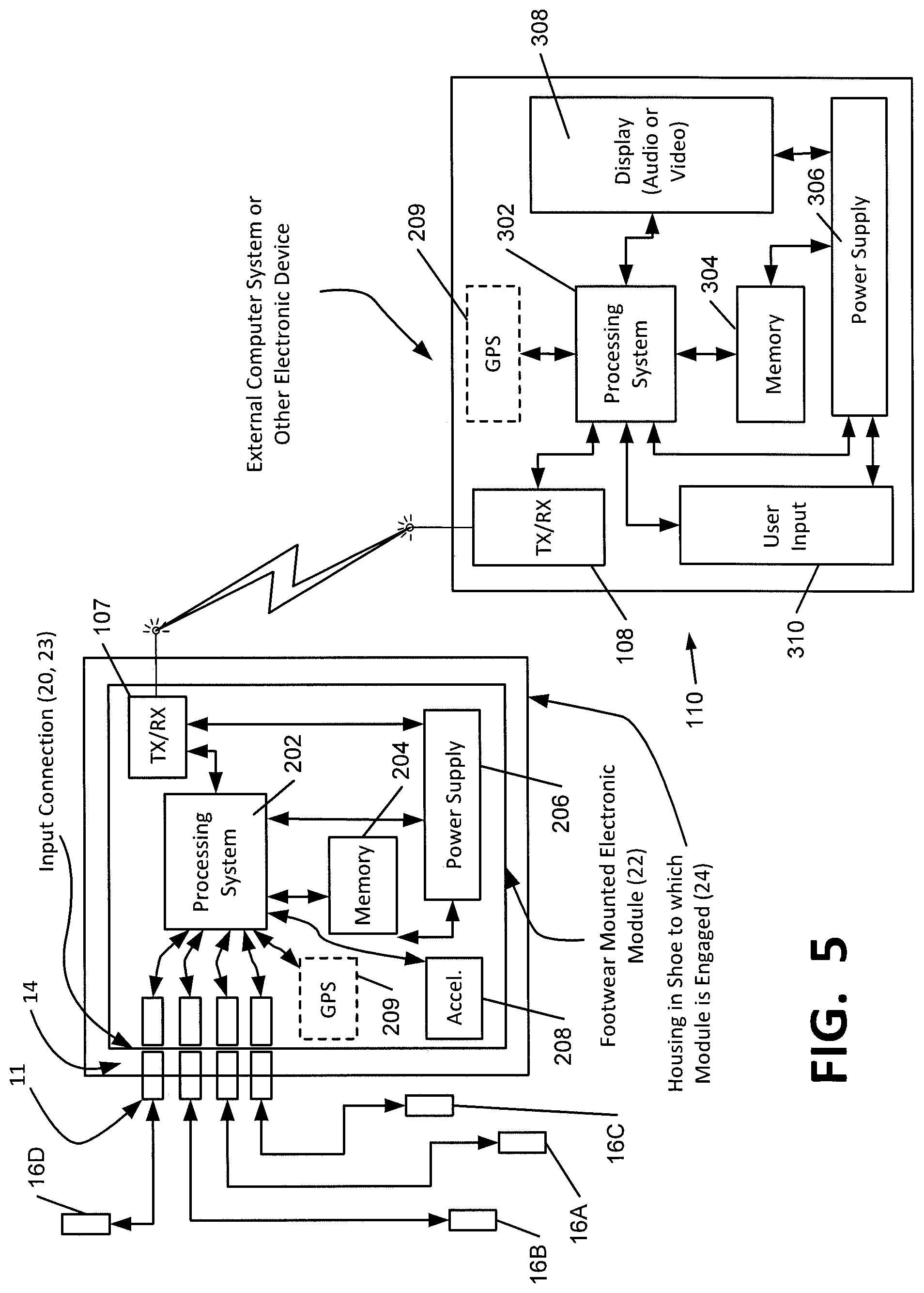
FIG. 5 is a schematic diagram of one embodiment of an electronic module capable of use with a sensor system, in communication with an external electronic device;
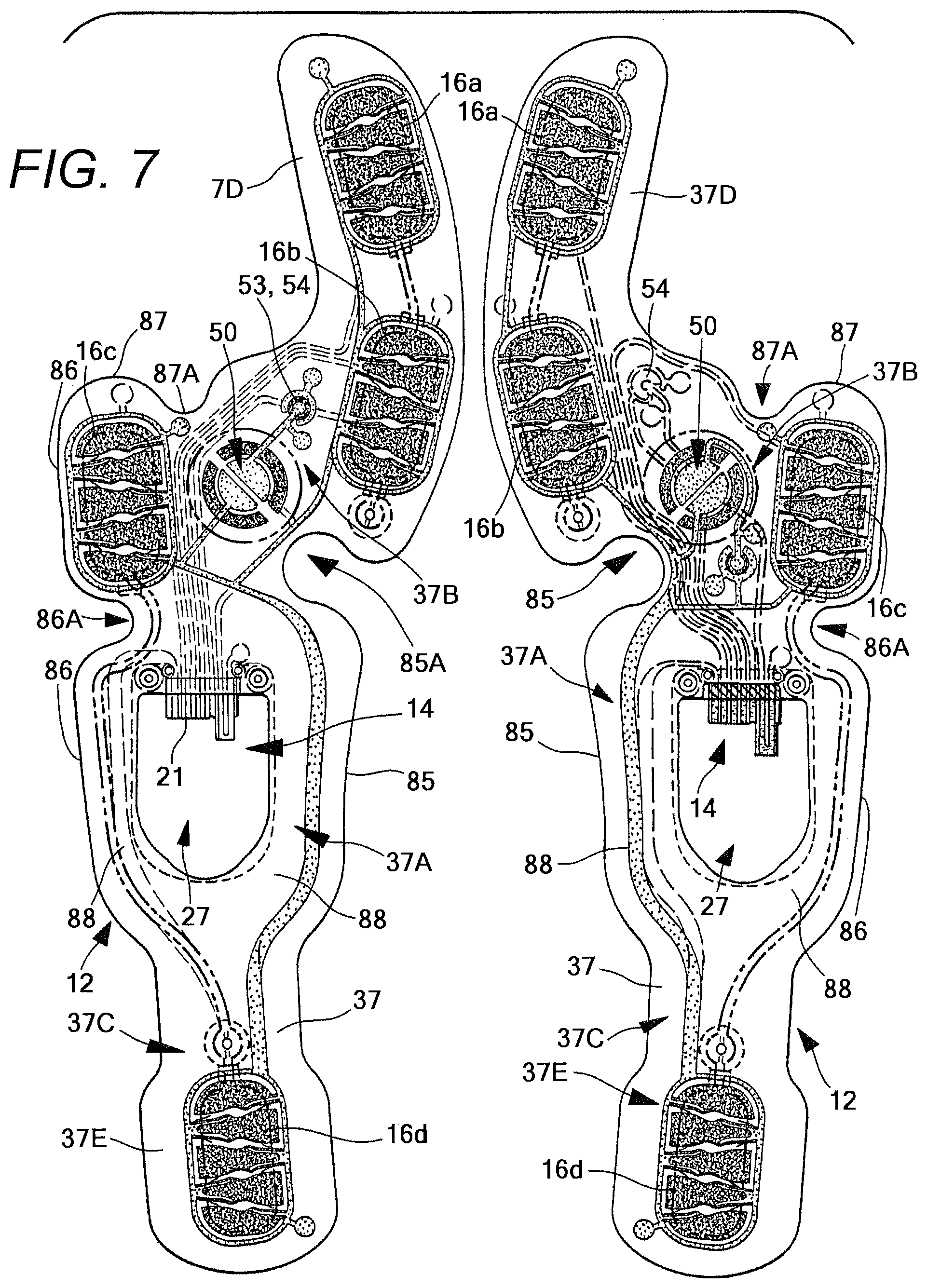
FIG. 6 is a top view of an insert of the sensor system of FIG. 3, adapted to be positioned within the sole structure of an article of footwear for a user's right foot;
FIG. 7 is a top view of the insert of FIG. 6 and a similar sensor system adapted for use in the sole structure of an article of footwear for a user's left foot;
FIG. 8 is an exploded perspective view of the insert of FIG. 6, showing four different layers;
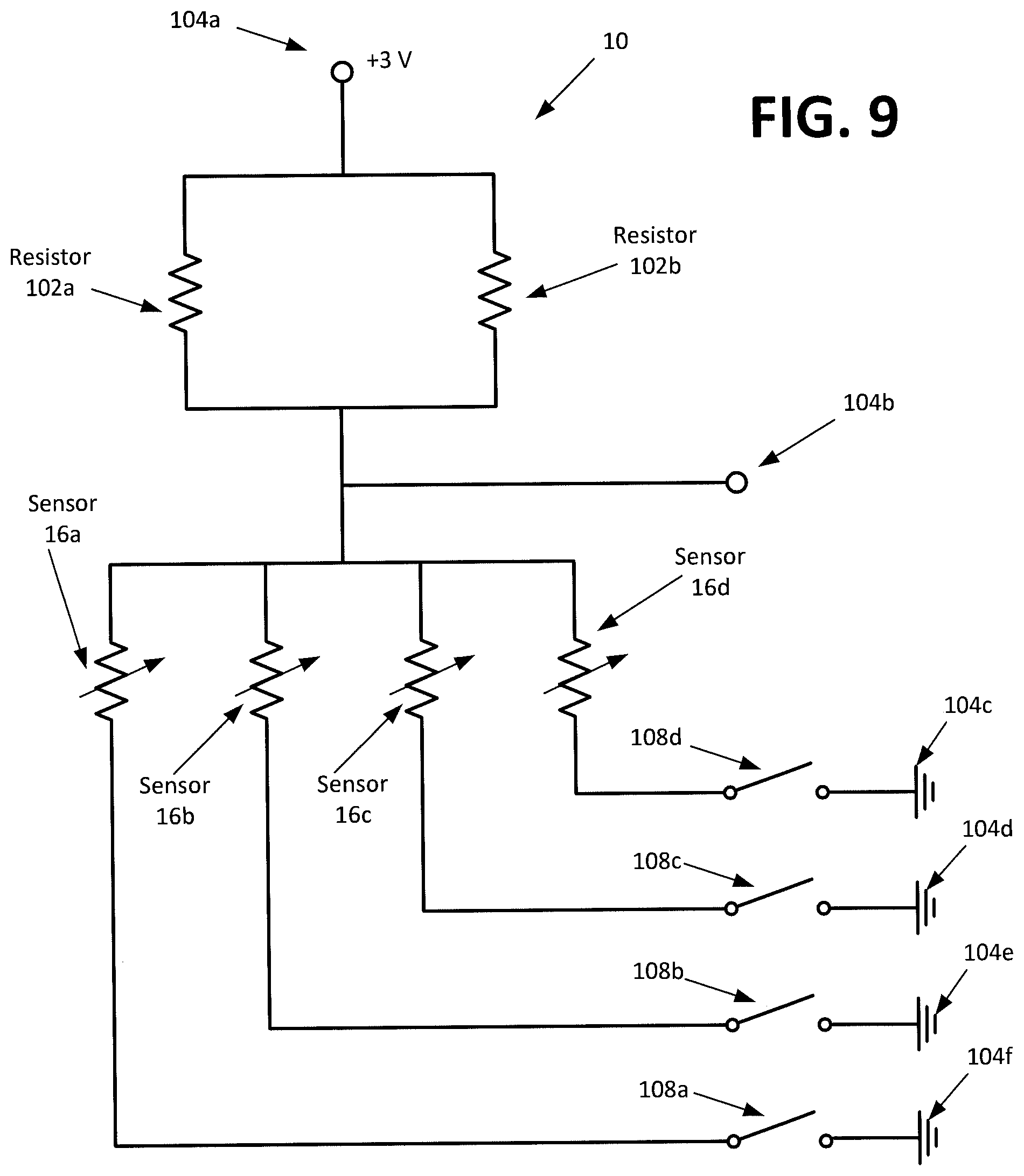
FIG. 9 is a schematic circuit diagram illustrating one embodiment of a circuit formed by the components of the sensor system of FIG. 3;
FIG. 10 is a schematic diagram of a pair of shoes, each containing a sensor system, in a mesh communication mode with an external device;
FIG. 11 is a schematic diagram of a pair of shoes, each containing a sensor system, in a "daisy chain" communication mode with an external device;
FIG. 12 is a schematic diagram of a pair of shoes, each containing a sensor system, in an independent communication mode with an external device;
FIG. 13 is a plot showing pressure vs. resistance for one embodiment of a sensor according to aspects of the present invention;
FIG. 14A is a perspective view of one embodiment of a port and a housing for connection to an electronic module, attached to an insert member;
FIG. 14B is a cross-section view of the port and housing of FIG. 14A;
FIG. 15 is a perspective view of a module according to aspects of the present invention;
FIG. 16 is a side view of the module of FIG. 15;
FIG. 17 is a top view of another embodiment of a sole member for an article of footwear incorporating one embodiment of a sensor system that is configured for use in connection with aspects of the present invention;
FIG. 18A is a schematic view of one embodiment of a system of electronic connections of the components of the sensor system illustrated in FIG. 17;
FIG. 18B is a schematic view of another embodiment of a system of electronic connections of the components of the sensor system illustrated in FIG. 17;
FIG. 19 is a schematic circuit diagram illustrating one embodiment of a circuit formed by the components of the sensor system of FIG. 17;
FIG. 20 is a top view of another embodiment of a sole member for an article of footwear incorporating one embodiment of a sensor system that is configured for use in connection with aspects of the present invention;
FIG. 21 is a perspective view of an insert used with the sensor system of FIG. 20;
FIG. 22 illustrates a sensor of the sensor system of FIG. 20, as well as a schematic illustration of the function of the sensor;
FIG. 23 is a top view of another embodiment of an insert usable with the sensor system of FIG. 20;
FIG. 24 is a top view of another embodiment of a sensor system that is configured for use in connection with aspects of the present invention;
FIG. 25 is a schematic view of a sensor of the sensor system of FIG. 24;
FIG. 26 is a top view of another embodiment of a sensor system that is configured for use in connection with aspects of the present invention;
FIG. 27 is a top view of another embodiment of a sensor system that is configured for use in connection with aspects of the present invention; and
FIG. 28 is a schematic illustration of a method of functioning of the sensor system of FIG. 26.
DETAILED DESCRIPTION
While this invention is susceptible of embodiment in many different forms, there are shown in the drawings, and will herein be described in detail, preferred embodiments of the invention with the understanding that the present disclosure is to be considered as an exemplification of the principles of the invention and is not intended to limit the broad aspects of the invention to the embodiments illustrated and described.
Various embodiments of sensor systems and structure for incorporating sensor systems into articles of footwear are shown and described herein. It is understood that each such embodiment may utilize any of the features described herein with respect to other embodiments, as well as any features described in U.S. patent application Ser. Nos. 13/401,918, 13/401,916, and 13/401,914, filed Feb. 22, 2012; U.S. patent application Ser. Nos. 13/399,778, 13/399,786, 13/399,916, and 13/399,935, filed Feb. 17, 2012; and U.S. patent application Ser. Nos. 12/483,824 and 12/483,828, filed Jun. 12, 2009, which applications are all incorporated by reference herein.
Embodiments of sensor systems described herein may be used in connection with an article of footwear, such as a shoe, which is shown as an example in FIGS. 1-2 and generally designated with the reference numeral 100. The footwear 100 can take many different forms, including, for example, various types of athletic footwear. In one exemplary embodiment, the shoe 100 generally includes a force and/or pressure sensor system 12 operably connected to a universal communication port 14. As described in greater detail below, the sensor system 12 collects performance data relating to a wearer of the shoe 100. Through connection to the universal communication port 14, multiple different users can access the performance data for a variety of different uses as described in greater detail below.
An article of footwear 100 is depicted in FIGS. 1-2 as including an upper 120 and a sole structure 130. For purposes of reference in the following description, footwear 100 may be divided into three general regions: a forefoot region 111, a midfoot region 112, and a heel region 113, as illustrated in FIG. 1. Regions 111-113 are not intended to demarcate precise areas of footwear 100. Rather, regions 111-113 are intended to represent general areas of footwear 100 that provide a frame of reference during the following discussion. Although regions 111-113 apply generally to footwear 100, references to regions 111-113 also may apply specifically to upper 120, sole structure 130, or individual components included within and/or formed as part of either upper 120 or sole structure 130.
As further shown in FIGS. 1 and 2, the upper 120 is secured to sole structure 130 and defines a void or chamber for receiving a foot. For purposes of reference, upper 120 includes a lateral side 121, an opposite medial side 122, and a vamp or instep area 123. Lateral side 121 is positioned to extend along a lateral side of the foot (i.e., the outside) and generally passes through each of regions 111-113. Similarly, medial side 122 is positioned to extend along an opposite medial side of the foot (i.e., the inside) and generally passes through each of regions 111-113. Vamp area 123 is positioned between lateral side 121 and medial side 122 to correspond with an upper surface or instep area of the foot. Vamp area 123, in this illustrated example, includes a throat 124 having a lace 125 or other desired closure mechanism that is utilized in a conventional manner to modify the dimensions of upper 120 relative the foot, thereby adjusting the fit of footwear 100. Upper 120 also includes an ankle opening 126 that provides the foot with access to the void within upper 120. A variety of materials may be used for constructing upper 120, including materials that are conventionally utilized in footwear uppers. Accordingly, upper 120 may be formed from one or more portions of leather, synthetic leather, natural or synthetic textiles, polymer sheets, polymer foams, mesh textiles, felts, non-woven polymers, or rubber materials, for example. The upper 120 may be formed from one or more of these materials wherein the materials or portions thereof are stitched or adhesively bonded together, e.g., in manners that are conventionally known and used in the art.
Upper 120 may also include a heel element (not shown) and a toe element (not shown). The heel element, when present, may extend upward and along the interior surface of upper 120 in the heel region 113 to enhance the comfort of footwear 100. The toe element, when present, may be located in forefoot region 111 and on an exterior surface of upper 120 to provide wear-resistance, protect the wearer's toes, and assist with positioning of the foot. In some embodiments, one or both of the heel element and the toe element may be absent, or the heel element may be positioned on an exterior surface of the upper 120, for example. Although the configuration of upper 120 discussed above is suitable for footwear 100, upper 120 may exhibit the configuration of any desired conventional or non-conventional upper structure without departing from this invention.
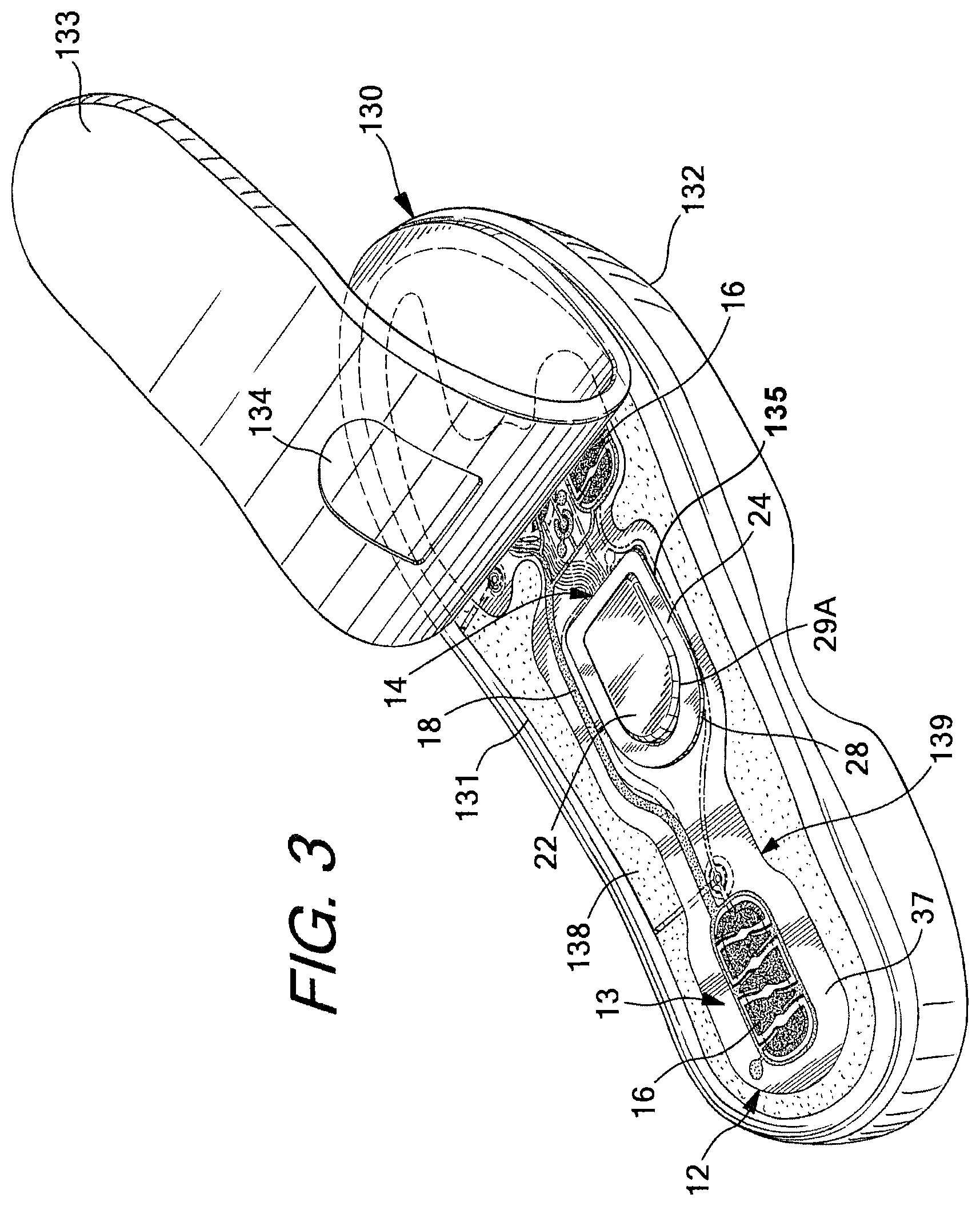
As shown in FIG. 3, the sole structure 130 is secured to a lower surface of upper 120 and may have a generally conventional shape. The sole structure 130 may have a multipiece structure, e.g., one that includes a midsole 131, an outsole 132, and a foot contacting member 133. The foot contacting member 133 is typically a thin, compressible member that may be located within the void in upper 120 and adjacent to a lower surface of the foot (or between the upper 120 and midsole 131) to enhance the comfort of footwear 100. In various embodiments, the foot contacting member 133 may be a sockliner, a strobel, an insole member, a bootie element, a sock, etc. In the embodiment shown in FIGS. 3-4, the foot contacting member 133 is an insole member or a sockliner. The term "foot contacting member," as used herein does not necessarily imply direct contact with the user's foot, as another element may interfere with direct contact. Rather, the foot contacting member forms a portion of the inner surface of the foot-receiving chamber of an article of footwear. For example, the user may be wearing a sock that interferes with direct contact. As another example, the sensor system 12 may be incorporated into an article of footwear that is designed to slip over a shoe or other article of footwear, such as an external bootie element or shoe cover. In such an article, the upper portion of the sole structure may be considered a foot contacting member, even though it does not directly contact the foot of the user. In some arrangements, an insole or sockliner may be absent, and in other embodiments, the footwear 100 may have a foot contacting member positioned on top of an insole or sockliner.
Midsole member 131 may be or include an impact attenuating member, and may include multiple members or elements in some embodiments. For example, the midsole member 131 may be formed of polymer foam material, such as polyurethane, ethylvinylacetate, or other materials (such as phylon, phylite, etc.) that compress to attenuate ground or other contact surface reaction forces during walking, running, jumping, or other activities. In some example structures according to this invention, the polymer foam material may encapsulate or include various elements, such as a fluid-filled bladder or moderator, that enhance the comfort, motion-control, stability, and/or ground or other contact surface reaction force attenuation properties of footwear 100. In still other example structures, the midsole 131 may include additional elements that compress to attenuate ground or other contact surface reaction forces. For instance, the midsole 131 may include column type elements to aid in cushioning and absorption of forces.
Outsole 132 is secured to a lower surface of midsole 131 in this illustrated example footwear structure 100 and is formed of a wear-resistant material, such as rubber or a flexible synthetic material, such as polyurethane, that contacts the ground or other surface during ambulatory or other activities. The material forming outsole 132 may be manufactured of suitable materials and/or textured to impart enhanced traction and slip resistance. The outsole 132 and midsole 131 shown in FIGS. 1 and 2 is shown to include a plurality of incisions or sipes 136 in either or both sides of the outsole 132, although many other types of outsoles 132 with various types of treads, contours, and other structures may be used in connection with the present invention. It is understood that embodiments of the present invention may be used in connection with other types and configurations of shoes, as well as other types of footwear and sole structures.
FIGS. 1-4 illustrate exemplary embodiments of the footwear 100 incorporating a sensor system 12 in accordance with the present invention, and FIGS. 3-8 illustrate exemplary embodiments of the sensor system 12. The sensor system 12 includes an insert member 37 having a force and/or pressure sensor assembly 13 connected thereto. It is understood that the use of the insert member 37 is one embodiment, and that an article of footwear including a different type of sensor system 12 may be utilized in connection with aspects described herein. It is also understood that insert 37 may have any number of different configurations, shapes, and structures, and including a different number and/or configuration of sensors 16, and a different insert structure or peripheral shape.
The insert member 37 is configured to be positioned in contact with the sole structure 130 of the footwear 100, and in one embodiment, the insert member 37 is configured to be positioned underneath the foot contacting member 133 and over the top of the midsole member 131 and in general confronting relation. The sensor assembly 13 includes a plurality of sensors 16, and a communication or output port 14 in communication with the sensor assembly 13 (e.g., electrically connected via conductors). The port 14 is configured for communicating data received from the sensors 16, such as to an electronic module (also referred to as an electronic control unit) 22 as described below. The port 14 and/or the module 22 may be configured to communicate with an external device, as also described below. In the embodiment illustrated in FIGS. 3-8, the system 12 has four sensors 16: a first sensor 16a at the big toe (first phalange or hallux) area of the shoe, two sensors 16b-c at the forefoot area of the shoe, including a second sensor 16b at the first metatarsal head region and a third sensor 16c at the fifth metatarsal head region, and a fourth sensor 16d at the heel. These areas of the foot typically experience the greatest degree of pressure during movement. Each sensor 16 is configured for detecting a pressure exerted by a user's foot on the sensor 16. The sensors communicate with the port 14 through sensor leads 18, which may be wire leads and/or another electrical conductor or suitable communication medium. For example, in the embodiment of FIGS. 3-8, the sensor leads 18 may be an electrically conductive medium that is printed on the insert member 37, such as a silver-based ink or other metallic ink, such as an ink based on copper and/or tin. The leads 18 may alternately be provided as thin wires in one embodiment. In other embodiments, the leads 18 may be connected to the foot contacting member 133, the midsole member 131, or another member of the sole structure 130.
Other embodiments of the sensor system 12 may contain a different number or configuration of sensors 16, and generally include at least one sensor 16. For example, in one embodiment, the system 12 includes a much larger number of sensors, and in another embodiment, the system 12 includes two sensors, one in the heel and one in the forefoot of the shoe 100. In addition, the sensors 16 may communicate with the port 14 in a different manner, including any known type of wired or wireless communication, including Bluetooth and near-field communication. A pair of shoes may be provided with sensor systems 12 in each shoe of the pair, and it is understood that the paired sensor systems may operate synergistically or may operate independently of each other, and that the sensor systems in each shoe may or may not communicate with each other. The communication of the sensor systems 12 is described in greater detail below. It is understood that the sensor system 12 may be provided with computer programs/algorithms to control collection and storage of data (e.g., pressure data from interaction of a user's foot with the ground or other contact surface), and that these programs/algorithms may be stored in and/or executed by the sensors 16, the module 22, and/or the external device 110.
The sensor system 12 can be positioned in several configurations in the sole 130 of the shoe 100. In the examples shown in FIGS. 3-4, the port 14, the sensors 16, and the leads 18 can be positioned between the midsole 131 and the foot contacting member 133, such as by positioning the insert member 37 between the midsole 131 and the foot contacting member 133. The insert member 37 may be connected to one or both of the midsole and the foot contacting member 133 in one embodiment. A cavity or well 135 can be located in the midsole 131 and/or in the foot contacting member 133 for receiving the electronic module 22, as described below, and the port 14 may be accessible from within the well 135 in one embodiment. The well 135 may further contain a housing 24 for the module 22, and the housing 24 may be configured for connection to the port 14, such as by providing physical space for the port 14 and/or by providing hardware for interconnection between the port 14 and the module 22. In the embodiment shown in FIGS. 3-4, the well 135 is formed by a cavity in the upper major surface of the midsole 131. As shown in FIGS. 3-4, the sole structure 130 may include a compressible sole member 138 that has a hole formed therein to receive the housing 24, which provides access to the well 135 and/or may be considered a portion of the well 135. The insert 37 can be placed on top of the compressible sole member 138 to place the housing 24 in the well 135. The compressible sole member 138 may confront the midsole 131 in one embodiment, and may be in direct contact with the midsole 131. It is understood that the compressible sole member 138 may confront the midsole 131 with one or more additional structures positioned between the compressible sole member 138 and the midsole 131, such as a strobel member. In the embodiment of FIGS. 3-4, the compressible sole member 138 is in the form of a foam member 138 (e.g. an EVA member) located between the foot contacting member 133 and the midsole 131, which may be considered a lower insole/sockliner in this embodiment. The foam member 138 may be bonded to a strobel (not shown) of the midsole 131 in one embodiment, such as by use of an adhesive, and may cover any stitching on the strobel, which can prevent abrasion of the insert 37 by the stitching.
In the embodiment shown in FIGS. 3-4, the housing 24 has a plurality of walls, including side walls 25 and a base wall 26, and also includes a flange or lip 28 that extends outward from the tops of the side walls 25 and is configured for connection to the insert 37. In one embodiment, the flange 28 is a separate member that connects to a tub 29 to form the housing 24, via pegs 28A that connect through holes 28B in the insert 37 located at the front end of the hole 27. The pegs 28A may be connected via ultrasonic welding or other technique, and may be received in receivers in one embodiment. In an alternate embodiment, an article of footwear 100 may be manufactured with the tub 29 formed in the sole structure 130, and the flange 28 may be later connected, such as by a snap connection, optionally after other portions of the port have also been assembled. The housing 24 may include retaining structure to retain the module 22 within the housing 24, and such retaining structure may be complementary with retaining structure on the module 22, such as a tab/flange and slot arrangement, complementary tabs, locking members, friction-fit members, etc. The housing 24 also includes a finger recess 29A located in the flange 28 and/or the tub 29, which provides room for the user's finger to engage the module 22 to remove the module 22 from the housing 24. The flange 28 provides a wide base engaging the top of the insert 37, which spreads out the forces exerted on the insert 37 and/or on the foot contacting member 133 by the flange 28, which creates less likelihood of severe deflection and/or damage of such components. The rounded corners on the flange 28 also assists in avoiding damage to the insert 37 and/or the foot contacting member 133. It is understood that the flange 28 may have a different shape and/or contour in other embodiments, and may provide similar functionality with different shapes and/or contours.
The foot contacting member 133 is configured to be placed on top of the foam member 138 to cover the insert 37, and may contain an indent 134 in its lower major surface to provide space for the housing 24, as shown in FIG. 3. The foot contacting member 133 may be adhered to the foam member 138, and in one embodiment, may be adhered only in the forefoot region to permit the foot contacting member 133 to be pulled up to access the module 22, as shown in FIG. 3. Additionally, the foot contacting member 133 may include a tacky or high-friction material (not shown) located on at least a portion of the underside to resist slippage against the insert 37 and/or the foam member 138, such as a silicone material. For example, in an embodiment where the foot contacting member 133 is adhered in the forefoot region and free in the heel region (e.g. FIG. 3), the foot contacting member 133 may have the tacky material located on the heel region. The tacky material may also provide enhanced sealing to resist penetration of dirt into the sensor system. In another embodiment, the foot contacting member 133 may include a door or hatch (not shown) configured to be located over the port 14 and sized to permit insertion and/or removal of the module 22 through the foot contacting member 133, which door or hatch may be opened in various manners, such as swinging on a hinge or removal of a plug-like element. In one embodiment, the foot contacting member 133 may also have graphic indicia (not shown) thereon, as described below.
In one embodiment, as shown in FIGS. 3-4, the foam member 138 may also include a recess 139 having the same peripheral shape as the insert 37 to receive the insert 37 therein, and the bottom layer 69 (FIG. 8) of the insert member 37 may include adhesive backing to retain the insert 37 within the recess 139. In one embodiment, a relatively strong adhesive, such as a quick bonding acrylic adhesive, may be utilized for this purpose. The insert 37 has a hole or space 27 for receiving and providing room for the housing 24, and the foam member 138 in this embodiment may also allow the housing 24 to pass completely through into and/or through at least a portion of the strobel and/or the midsole 131. In the embodiment shown in FIGS. 3-4, the foot contacting member 133 may have a thickness that is reduced relative to a typical foot contacting member 133 (e.g. sockliner), with the thickness of the foam member 138 being substantially equal to the reduction in thickness of the foot contacting member 133, to provide equivalent cushioning. In one embodiment, the foot contacting member 133 may be a sockliner with a thickness of about 2-3 mm, and the foam member 138 may have a thickness of about 2 mm, with the recess 139 having a depth of about 1 mm. The foam member 138 may be adhesively connected to the insert member 37 prior to connecting the foam member 138 to the article of footwear 100 in one embodiment. This configuration permits the adhesive between the foam member 138 and the insert 37 to set in a flat condition before attaching the foam member to the strobel or other portion of the footwear 100, which is typically bends or curves the foam member 138 and may otherwise cause delamination. The foam member 138 with the insert 37 adhesively attached may be provided in this configuration as a single product for insertion into an article of footwear 100 in one embodiment. The positioning of the port 14 in FIGS. 3-4 not only presents minimal contact, irritation, or other interference with the user's foot, but also provides easy accessibility by simply lifting the foot contacting member 133.
In the embodiment of FIGS. 3-4, the housing 24 extends completely through the insert 37 and the foam member 138, and the well 135 may also extend completely through the strobel and partially into the midsole 131 of the footwear 100 to receive the housing 24. In another embodiment, the well 135 may be differently configured, and may be positioned completely underneath the strobel in one embodiment, with a window through the strobel to permit access to the module 22 in the well 135. The well 135 may be formed using a variety of techniques, including cutting or removing material from the strobel and/or the midsole 131, forming the strobel and/or the midsole 131 with the well contained therein, or other techniques or combinations of such techniques. The housing 24 may fit closely with the walls of the well 135, which can be advantageous, as gaps between the housing 24 and the well 135 may be sources of material failure. The process of removing the piece 135 may be automated using appropriate computer control equipment.
The well 135 may be located elsewhere in the sole structure 130 in further embodiments. For example, the well 135 may be located in the upper major surface of the foot contacting member 133 and the insert 37 can be placed on top of the foot contacting member 133. As another example, the well 135 may be located in the lower major surface of the foot contacting member 133, with the insert 37 located between the foot contacting member 133 and the midsole 131. As a further example, the well 135 may be located in the outsole 132 and may be accessible from outside the shoe 100, such as through an opening in the side, bottom, or heel of the sole 130. In the configurations illustrated in FIGS. 3-4, the port 14 is easily accessible for connection or disconnection of an electronic module 22, as described below. In another embodiment, the foot contacting member 133 may have the insert 37 connected to the bottom surface, and the port 14 and the well 135 may be formed in the sole structure 130. The interface 20 is positioned on the side of the housing 24 as similarly shown with respect to other embodiments, although it is understood that the interface 20 could be positioned elsewhere, such as for engagement through the top of the module 22. The module 22 may be altered to accommodate such a change. Other configurations and arrangements of the housing 24, the insert 37, the module 22, and/or the interface may be utilized in further embodiments.
In other embodiments, the sensor system 12 can be positioned differently. For example, in one embodiment, the insert 37 can be positioned within the outsole 132, midsole 131, or foot contacting member 133. In one exemplary embodiment, insert 37 may be positioned within a foot contacting member 133 positioned above an insole member, such as a sock, sockliner, interior footwear bootie, or other similar article, or may be positioned between the foot contacting member 133 and the insole member. Still other configurations are possible. As discussed, it is understood that the sensor system 12 may be included in each shoe in a pair.
The insert member 37 in the embodiment illustrated in FIGS. 3-8 is formed of multiple layers, including at least a first layer 66 and a second layer 68. The first and second layers 66, 68 may be formed of a flexible film material, such as a Mylar.RTM. or other PET (polyethylene terephthalate) film, or another polymer film, such as polyamide. In one embodiment, the first and second layers 66, 68 may each be PET films having thicknesses of 0.05-0.2 mm, such as a thickness of 125 .mu.m. Additionally, in one embodiment, each of the first and second layers 66, 68 has a minimum bend radius of equal to or less than 2 mm. The insert 37 may further include a spacer layer 67 positioned between the first and second layers 66, 68 and/or a bottom layer 69 positioned on the bottom of the insert 37 below the second layer 68, which are included in the embodiment illustrated in FIGS. 3-8. The layers 66, 67, 68, 69 of the insert 37 are stacked on top of each other and in confronting relation to each other, and in one embodiment, the layers 66, 67, 68, 69 all have similar or identical peripheral shapes and are superimposed on one another (FIG. 8). In one embodiment, the spacer layer 67 and the bottom layer 69 may each have a thickness of 89-111 .mu.m, such as a thickness of 100 .mu.m. The entire thickness of the insert member 37 may be about 450 .mu.m in one embodiment, or about 428-472 .mu.m in another embodiment, and about 278-622 .mu.m in a further embodiment. The insert 37 may also include additional adhesive that is 100-225 .mu.m thick, and may further include one or more selective reinforcement layers, such as additional PET layers, in other embodiments. Additionally, in one embodiment, the entire four-layer insert as described above has a minimum bend radius of equal to or less than 5 mm. It is understood that the orientations of the first and second layers 66, 68 may be reversed in another embodiment, such as by placing the second layer 68 as the top layer and the first layer 66 below the second layer 68. In the embodiment of FIGS. 3-8, the first and second layers 66, 68 have various circuitry and other components printed thereon, including the sensors 16, the leads 18, resistors 53, 54, a pathway 50, dielectric patches 80, and other components, which are described in greater detail below. The components are printed on the underside of the first layer 66 and on the upper side of the second layer 68 in the embodiment of FIGS. 3-8, however in other embodiments, at least some components may be printed on the opposite sides of the first and second layers 66, 68. It is understood that components located on the first layer 66 and/or the second layer 68 may be moved/transposed to the other layer 66, 68.
The layers 66, 67, 68, 69 can be connected together by an adhesive or other bonding material in one embodiment. The spacer layer 67 may contain adhesive on one or both surfaces in one embodiment to connect to the first and second layers 66, 68. The bottom layer 69 may likewise have adhesive on one or both surfaces, to connect to the second layer 68 as well as to the article of footwear 100. The first or second layers 66, 68 may additionally or alternately have adhesive surfaces for this purpose. A variety of other techniques can be used for connecting the layers 66, 67, 68, 69 in other embodiments, such as heat sealing, spot welding, or other known techniques.
In the embodiment illustrated in FIGS. 3-8, the sensors 16 are force and/or pressure sensors for measuring pressure and/or force on the sole 130. The sensors 16 have a resistance that decreases as pressure on the sensor 16 increases, such that measurement of the resistance through the port 14 can be performed to detect the pressure on the sensor 16. The sensors 16 in the embodiment illustrated in FIGS. 3-8 are elliptical or obround in shape, which enables a single sensor size to be utilized in several different shoe sizes. The sensors 16 in this embodiment each include two contacts 40, 42, including a first contact 40 positioned on the first layer 66 and a second contact 42 positioned on the second layer 68. It is understood that the figures illustrating the first layer 66 herein are top views, and that the electronic structures (including the contacts 40, the leads 18, etc.) are positioned on the bottom side of the first layer 66 and viewed through a transparent or translucent first layer 66 unless specifically noted otherwise. The contacts 40, 42 are positioned opposite each other and are in superimposed relation to each other, so that pressure on the insert member 37, such as by the user's foot, causes increased engagement between the contacts 40, 42. The resistance of the sensor 16 decreases as the engagement between the contacts 40, 42 increases, and the module 22 is configured to detect pressure based on changes in resistance of the sensors 16. In one embodiment, the contacts 40, 42 may be formed by conductive patches that are printed on the first and second layers 66, 68, such as in the embodiment of FIGS. 3-8, and the two contacts 40, 42 may be formed of the same or different materials. Additionally, in one embodiment, the leads 18 are formed of a material that has a higher conductivity and lower resistivity than the material(s) of the sensor contacts 40, 42. For example, the patches may be formed of carbon black or another conductive carbon material. Further, in one embodiment, the two contacts 40, 42 may be formed of the same material or two materials with similar hardnesses, which can reduce abrasion and wear due to differences in hardness of the materials in contact with each other. In this embodiment, the first contacts 40 are printed on the underside of the first layer 66, and the second contacts 42 are printed on the top side of the second layer 68, to permit engagement between the contacts 40, 42. The embodiment illustrated in FIGS. 3-8 includes the spacer layer 67, which has holes 43 positioned at each sensor 16 to permit engagement of the contacts 40, 42 through the spacer layer 67, while insulating other portions of the first and second layers 66, 68 from each other. In one embodiment, each hole 43 is aligned with one of the sensors 16 and permits at least partial engagement between the contacts 40, 42 of the respective sensor 16. In the embodiment illustrated in FIGS. 3-8, the holes 43 are smaller in area than the sensor contacts 40, 42, allowing the central portions of the contacts 40, 42 to engage each other, while insulating outer portions of the contacts 40, 42 and the distribution leads 18A from each other (See, e.g., FIG. 8). In another embodiment, the holes 43 may be sized to permit engagement between the contacts 40, 42 over their entire surfaces. It is understood that the size, dimensions, contours, and structure of the sensors 16 and the contacts 40, 42 may be altered in other embodiments while retaining similar functionality. It is also understood that sensors 16 having the same sizes may be utilized in different sizes of inserts 37 for different shoe sizes, in which case the dimensions of the sensors 16 relative to the overall dimensions of the insert 37 may be different for different insert 37 sizes. In other embodiments, the sensor system 12 may have sensors 16 that are differently configured than the sensors 16 of the embodiment of FIGS. 3-8. In a further example, the sensors 16 may utilize a different configuration that does not include carbon-based or similar contacts 40, 42 and/or may not function as a resistive sensor 16. Examples of such sensors include a capacitive pressure sensor or a strain gauge pressure sensor, among other examples.
As further shown in FIGS. 3-8, in one embodiment, the insert 37 may include an internal airflow system 70 configured to allow airflow through the insert 37 during compression and/or flexing of the insert 37. FIG. 8 illustrates the components of the airflow system 70 in greater detail. The airflow system 70 may include one or more air passages or channels 71 that lead from the sensors 16 to one or more vents 72, to allow air to flow from the sensor 16 during compression, between the first and second layers 66, 68 and outward through the vent(s) 72 to the exterior of the insert 37. The airflow system 70 resists excessive pressure buildup during compression of the sensors 16, and also permits consistent separation of the contacts 40, 42 of the sensors 16 at various air pressures and altitudes, leading to more consistent performance. The channels 71 may be formed between the first and second layers 66, 68. As shown in FIG. 8, the spacer layer 67 has the channels 71 formed therein, and the air can flow through these channels 71 between the first and second layers 66, 68, to the appropriate vent(s) 72. The vents 72 may have filters (not shown) covering them in one embodiment. These filters may be configured to permit air, moisture, and debris to pass out of the vents 72 and resist moisture and debris passage into the vents 72. In another embodiment, the insert 37 may not contain a spacer layer, and the channels 71 may be formed by not sealing the layers 66, 68 together in a specific pattern, such as by application of a non-sealable material. Thus, the airflow system 70 may be considered to be integral with or directly defined by the layers 66, 68 in such an embodiment. In other embodiments, the airflow system 70 may contain a different number or configuration of air channels 71, vents 72, and/or other passages.
In the embodiment illustrated in FIGS. 3-8, the airflow system 70 includes two vents 72 and a plurality of air channels 71 connecting each of the four sensors 16 to one of the vents 72. The spacer layer 67 includes holes 43 at each sensor in this embodiment, and the channels 71 are connected to the holes 43 to permit air to flow away from the sensor 16 through the channel 71. Additionally, in this embodiment, two of the sensors 16 are connected to each of the vents 72 through channels 71. For example, as illustrated in FIGS. 4 and 8 the first metatarsal sensor 16b has a channel 71 that extends to a vent 72 slightly behind the first metatarsal area of the insert 37, and the first phalangeal sensor 16a has a channel 71 that also extends to the same vent 72, via a passageway that includes traveling through the first metatarsal sensor 16b. In other words, the first phalangeal sensor 16a has a channel 71 that extends from the hole 43 at the first phalangeal sensor 16a to the hole 43 at the first metatarsal sensor 16b, and another channel 71 extends from the first metatarsal sensor 16b to the vent 72. The fifth metatarsal sensor 16c and the heel sensor 16d also share a common vent 72, located in the heel portion of the insert 37. One channel 71 extends rearward from the hole 43 at the fifth metatarsal sensor 16c to the vent 72, and another channel 71 extends forward from the hole 43 at the heel sensor 16d to the vent 72. Sharing the vents 72 among multiple sensors can decrease expense, particularly by avoiding the need for additional filters 73. In other embodiments, the airflow system 70 may have a different configuration. For example, each sensor 16 may have its own individual vent 72, or more than two sensors 16 may share the same vent 72, in various embodiments.
Each vent 72 is formed as an opening in a bottom side of the second layer 68 (i.e. opposite the first layer 66), such that the opening permits outward flow of air, moisture, and/or debris from the airflow system 70, as seen in FIG. 8. In another embodiment, the vent 72 may include multiple openings. In a further embodiment, the vent 72 may additionally or alternately be formed by an opening in the first layer 66, causing the air to vent upwards out of the insert 37. In an additional embodiment, the vent 72 may be on the side (thin edge) of the insert 37, such as by extending the channel 71 to the edge, such that the channel 71 opens through the edge to the exterior of the insert 37. The venting of the air downward, as in the embodiment illustrated in FIGS. 3-8, makes it more difficult for debris to enter the vent 72. The bottom layer 69, if present, also includes apertures 74 located below the vents 72, to permit the air flowing out of the vents 72 to pass through the bottom layer 69. The apertures 74 are significantly larger than the vents 72, in order to allow filters to be adhesively attached to the second layer 68 through the bottom layer 69 around the periphery of each vent 72, as described below. Additionally, in this embodiment, each vent 72 has a reinforcement material 75 positioned around the vent 72, to add stability and strength to the material and prevent breaking/tearing. In the embodiment illustrated, the reinforcement material 75 is formed of the same material as the leads 18 (e.g. silver or other metallic ink) to facilitate printing, but may also be formed of the same material as the sensor contacts 40, 42 (e.g. carbon) or the dielectric material discussed herein.
The vents 72 in the embodiment illustrated in FIGS. 3-8 open downward and the air passing through the vents 72 passes downward toward the midsole 131 and toward the foam member 138 if present. In the embodiment illustrated in FIGS. 3-4, the foam member 138 has cavities 76 located directly below the vents 72 and configured such that the air exiting the vents passes into the respective cavity 76. Such cavities 76 may be formed as a slot that extends completely or partially through the foam member 138. This configuration allows air to pass out of the vents 72 without obstruction from the foam member 138. In the embodiment of FIGS. 3-4, each of the cavities 76 has a channel portion 77 extending laterally away from the cavity 76 and beyond the peripheral boundary of the insert 37. In other words, the channel portion 77 of the cavity 76 extends laterally from the vent 72 to a distal end 78 located outside the peripheral boundary of the insert 37. It is understood that if the foam member 138 has a recess 139 to receive the insert member 37, the distal end 78 of the channel portion 77 of the cavity 76 may also be located outside the peripheral boundary of the recess 139, as in the embodiment shown in FIGS. 3-4. This configuration permits air passing into the cavity 76 to exit the sole structure 130 by passing laterally through the channel portion 77 and then upward and/or outward away from the foam member 138. In another embodiment, the distal end 78 may stop at a point within the foam member 138 and still outside the peripheral boundary of the insert 37, which allows the air to vent upward out of the cavity 76 at the distal end 78 and provides the same or similar functionality. As stated above, the components of the airflow system 70 may be configured different in other embodiments.
Additionally, the foot contacting member 133 includes one or more passages (not shown) extending through the foot contacting member 133 located at the distal end 78 of the cavity 76, in the embodiment of FIGS. 3-8. The passages may be pinhole-type passages that extend vertically through the foot contacting member 133. In another embodiment, a different type of passage may be used, including slits or grooves, and at least one passage may extend laterally to a side of the foot contacting member 133, rather than upward through the thickness of the foot contacting member 133. The passages allow the air exiting through the vent 72 and outward through the cavity 76 to pass through the foot contacting member 133 and out of the sole structure 130. In another embodiment, the foot contacting member 133 may not include any passage(s). The foot contacting member 133 may still provide ventilation in a configuration without any passage(s), such as by using a breathable foam or other breathable material for constructing the foot contacting member 133.
In the embodiment of FIGS. 3-8, as described above, the spacer layer 67 generally insulates conductive members/components on the first and second layers 66, 68 from each other, except in areas where electrical contact is desired, such as at the pathway 50 and between the contacts 40, 42 of the sensors 16. The spacer layer 67 has holes 38, 43 to define areas of desired electrical contact between the layers 66, 68. The components of the airflow system 70, in particular the channels 71 may provide a route for shorting or other undesired electrical contact by one or more conductive members between the first and second layers 66, 68. In one embodiment, the sensor system 12 may include one or more patches of dielectric material 80 to resist or prevent undesired shorting by one or more conductive members across open areas of the spacer layer 67, such as the channels 71. This dielectric material 80 may be in the form of an acrylic ink or other UV-curable ink, or another insulating material suitable for the application. In the embodiment shown in FIGS. 3-8, the insert 37 has several patches of dielectric material 80 extending across the channel 71, to insulate the distribution leads 18A located around the sensor contacts 40, 42 from each other.
In the embodiment of FIGS. 3-8, the port 14, the sensors 16, and the leads 18 form a circuit 10 on the insert member 37. The port 14 has a plurality of terminals 11, with four of the terminals 11 each dedicated to one of the four sensors 16 individually, one terminal 11 for applying a voltage to the circuit 10, and one terminal 11 for voltage measurement. In this embodiment, the sensor system 12 also includes a pair of resistors 53, 54, each located on one of the layers 66, 68, and a pathway 50 connecting the circuitry on the first layer 66 with the circuitry on the second layer 68. The resistors 53, 54 provide a reference point for the module 22 to measure the resistance of each sensor 16, and permit the module 22 to convert the variable current from the active sensor 16 into a measurable voltage. Additionally, the resistors 53, 54 are arranged in parallel within the circuit 10, which compensates for variations in the circuit 10 and/or variations in the manufacturing processes used to create the resistors 53, 54, such as variations in conductivity of the inks used to print the leads 18 and/or the sensor contacts 40, 42. In one embodiment, the equivalent resistance of the two resistors 53, 54 is 1500+/-500 k.OMEGA.. In another embodiment, a single resistor 53, 54 or two resistors 53, 54 in series could be used. In a further embodiment, the resistors 53, 54 may be positioned elsewhere on the insert 37, or may be located within the circuitry of the module 22. A more technical depiction of the circuit 10 of this embodiment is described below and shown in FIG. 20.
FIG. 9 illustrates a circuit 10 that may be used to detect and measure pressure in accordance with an embodiment of the invention. The circuit 10 includes six terminals 104a-104f, including a power terminal 104a for applying a voltage to the circuit 10, a measurement terminal 104b for measuring a voltage as described below, and four sensor terminals 104c-104f, each of which is dedicated to one of the sensors 16a-16d individually, and each of which represents ground in this embodiment. The terminals 104a-104f represent the terminals 11 of the port 14. In the embodiment shown, fixed resistors 102a and 102b, which represent resistors 53 and 54, are connected in parallel. Fixed resistors 102a and 102b may be physically located on separate layers. The equivalent resistance across terminals 104a and 104b is determined by the well-known equation of: R.sub.eq=R.sub.102aR.sub.102b/(R.sub.102a+R.sub.102b) (Equation 1)
Where: R.sub.102a=Resistance of fixed resistors 102a R.sub.102b=Resistance of fixed resistors 102b R.sub.eq=Equivalent resistance
Electrically connecting fixed resistors 102a and 102b in parallel compensates for variations in the manufacturing processes used to create fixed resistors 102a and 102b. For example, if fixed resistor 102a has a resistance that deviates from a desired resistance, the deviation of the equivalent resistance determined by equation 1 is minimized by the averaging effect of fixed resistor 102b. One skilled in the art will appreciate that two fixed resistors are shown for illustration purposes only. Additional fixed resistors may be connected in parallel and each fixed resistor may be formed on a different layer.
In the embodiment shown in FIG. 9, fixed resistors 102a and 102b are connected to sensors 16a-16d. Sensors 16a-16d may be implemented with variable resistors that change resistance in response to changes in pressure, as described above. Each of sensors 16a-16d may be implemented with multiple variable resistors. In one embodiment, each of sensors 16a-16d is implemented with two variable resistors which are physically located on different layers and electrically connected in parallel. For example, as described above with respect to one embodiment, each sensor 16a-16d may contain two contacts 40, 42 that engage each other to a greater degree as applied pressure increases, and the resistance of the sensor 16a-16d may decrease as the engagement increases. As mentioned above, connecting resistors in parallel creates an equivalent resistance that minimizes deviations created during manufacturing processes. In another embodiment, the contacts 40, 42 may be arranged in series. Sensors 16a-16d may be connected to ground via switches 108a-108d. Switches 108a-108d may be closed one at a time to connect a sensor. In some embodiments, switches 108a-108d are implemented with transistors or integrated circuits.
In operation a voltage level, such as 3 volts, is applied at terminal 104a. Switches 108a-108d are closed one at a time to connect one of sensors 16a-16d to ground. When connected to ground, each of sensors 16a-16d forms a voltage divider with the combination of fixed resistors 102a and 102b. For example, when switch 108a is closed, the voltage between terminal 104a and ground is divided between the combination of fixed resistors 102a and 102b and sensor 16a. The voltage measured at terminal 104b changes as the resistance of sensor 16a changes. As a result, pressure applied to sensor 16a may be measured as a voltage level at terminal 104b. The resistance of the sensor 16a is measured utilizing the voltage applied to the sensor 16a in series with the combined fixed resistors 104a and 104b of known value. Similarly, selectively closing switches 108b-108d will generate voltage levels at terminal 104b that are related to the pressure applied at sensors 16b-16d. It is understood that the connections between the sensors 16a-d and the terminals 104c-f may be different in other embodiments. For example, the sensors 16a-d are connected to different pins of the interface 20 in the left shoe insert 37 as compared to the right shoe insert 37, as shown in FIG. 8. In another embodiment, the voltage level may be applied in the opposite manner, with the ground located at terminal 104a and the voltage applied at terminals 104c-f. In further embodiments, another circuit configuration may be used to achieve a similar result and functionality.
The two resistors 53, 54 have similar or identical structures in the embodiment illustrated, however it is understood that the resistors may have different structures in other embodiments. Each resistor 53, 54 has two sections 55, 56 spaced from each other and a bridge 57 positioned between and connecting the sections 55, 56. In one embodiment, the bridge 57 may be formed of a more resistive material than the sections 55, 56, and may thus provide the majority of the resistance of each resistor 53, 54. The sections 55, 56 may be at least partially formed of a high-conductivity material, such as a silver material. In the embodiment illustrated in FIGS. 3-9, the inner and outer sections 55, 56 are formed of the same material as the leads 18, such as a printed silver-based or other metallic-based ink. In this embodiment, the bridge 57 is formed of the same material as the sensor contacts 40, 42, such as carbon black or another conductive carbon material. It is understood that the inner and outer sections 55, 56 and/or the bridge 57 may be formed of different materials in other embodiments.
The pathway 50 generally permits continuous and/or uninterrupted electrical communication and passes electronic signals between the first and second layers 66, 68. In the embodiment of FIGS. 3-8, the port 14 is directly connected to the second layer 68, and the pathway 50 may serve as a vertical path between the port 14 and the sensor contacts 40 on the first layer 66, 68. In this embodiment, the pathway 50 includes conductive portions 51 on the first layer 66 and the second layer 68, such that conductive portions 51 may be in continuous engagement with each other to provide continuous electrical communication between the first and second layers 66, 68. The spacer layer 67 in this embodiment includes a hole 38 that is aligned with the pathway 50 and allows for continuous engagement between the conductive portions 51 through the spacer layer 67. Additionally, in the embodiment of FIGS. 3-5, each of the conductive portions 51 is divided into two sections 52 that are separated by an elongated gap 59. The gap 59 may be oriented to increase the durability of the pathway 50 during flexing of the insert 37, by serving as a flexing point to minimize bending of the conductive portions 51. The conductive portions 51 of the pathway 50 are formed of a conductive material, and in one embodiment, the conductive portions 51 may be formed of the same material as the leads 18, such as a silver-based ink or other metallic ink. In other embodiments, the pathway 50, and the components thereof described herein, may have a different size, shape, form, or location, and may be formed of a different material. Additionally, the pathway 50 may be at least partially surrounded by or bounded by a stiffening structure 60 in one embodiment to provide structural support and/or effects, such as assisting with engagement between the conductive portions 51. As illustrated in FIGS. 3-8, the conductive portions 51 are surrounded by a substantially annular stiffener 60. The stiffener 60 may be formed of any material that has suitable stiffness, and in one embodiment, may be formed of a material with greater stiffness than the material of the conductive portions 51, such as carbon black or other carbon-based material. Further, the hole 38 in the spacer layer 67 permits the conductive portions 51 to engage each other.
The insert 37 may be constructed by depositing the various components on a polymer (e.g. PET) film. In one embodiment, the insert 37 is constructed by first depositing the conductive metallic material on each layer 66, 68, such as by printing in the traced pattern of the leads 18 (including the distribution lead 18A, the conductive portions 51 of the pathway 50, the inner and outer sections 55, 56 of the resistors 53, 54, etc. The additional carbon material can then be deposited on each layer 66, 68, such as by printing, to form the contacts 40, 42, the stiffener 60 of the pathway 50, the bridge 57 of the resistors 53, 54, etc. Any additional components can then be deposited, such as any dielectric portions. The layers 66, 68 may be printed on PET sheets and then cut out to form the outer peripheral shape after printing in one embodiment.
The port 14 is configured for communication of data collected by the sensors 16 to an outside source, in one or more known manners. In one embodiment, the port 14 is a universal communication port, configured for communication of data in a universally readable format. In the embodiments shown in FIGS. 3-8 and 14, the port 14 includes an interface 20 for connection to an electronic module 22, shown in connection with the port 14 in FIG. 3. Additionally, in this embodiment, the port 14 is associated with the housing 24 for insertion of the electronic module 22, located in the well 135 in the middle arch or midfoot region of the midsole 131. As illustrated in FIGS. 3-8, the sensor leads 18 converge together to form a consolidated interface 20 at their terminals 11, in order to connect to the port 14. In one embodiment, the consolidated interface may include individual connection of the sensor leads 18 to the port interface 20, such as through a plurality of electrical contacts. In another embodiment, the sensor leads 18 could be consolidated to form an external interface, such as a plug-type interface or another configuration, and in a further embodiment, the sensor leads 18 may form a non-consolidated interface, with each lead 18 having its own separate terminal 11. As also described below, the module 22 may have an interface 23 for connection to the port interface 20 and/or the sensor leads 18.
In the embodiments shown in FIGS. 3-8 and 14, the interface 20 takes the form of electrical contacts or terminals 11. In one embodiment, the terminals 11 are formed on a tongue or extension 21 that extends from one of the layers 66, 68 into the hole 27 provided for the housing 24. The extension consolidates the ends of the leads 18 to a single area to form the interface 20. In the embodiment of FIGS. 3-8 and 14, the extension 21 extends from the second layer 68 into the hole 27, and is bent downward within the housing 24 to place the terminals 11 within the housing 24 and make the interface 20 accessible within the housing 24. The extension 21 may pass underneath the flange 28 of the housing 24 and through a slot or other space underneath the lip 28 in order to extend into the housing 24. In the configuration illustrated in FIGS. 3-8 and 14, the extension 21 bends downwardly into the well 135 and into the housing 24, as discussed above, to place the terminals 11 within the housing 24 and forming the interface 20 within the housing 24.
The housing 24 may contain connection structure, such as connector pins or springs for establishing connection between the interface 20 and the module 22, as shown in FIG. 14. In one embodiment, the port 14 includes an electrical connector 82 forming the interface 20, which may include contacts that individually attach to the terminals 11, as mentioned above. The connector 82 may connect to the extension 21 and the terminals 11 via a crimping connection. The interface 20 in this embodiment includes seven terminals: four terminals 11 each individually connected to one of the sensors 16, one terminal 11 serving as the measurement terminal (104b in FIG. 20), and one terminal serving as a power terminal (104a in FIG. 20) to apply a voltage to the circuit 10. As discussed above, the power terminal may instead be configured as a ground terminal in another embodiment, with the sensor terminals (104c-f in FIG. 20) being configured as power terminals. The seventh terminal may be utilized for powering of accessories, such as a unique identification chip 92 (see FIG. 14B). In one embodiment, the sixth and seventh terminals 11 are extended on a tail 21A that extends from the end of the extension 21. An accessory may be connected across the two terminals 11 on the tail 21A to power the accessory. The accessory may include a small printed circuit board (PCB) with a memory chip that are attached via anisotropic contact formation to the tail 21A. In one embodiment, an accessory chip may include information uniquely identifying the article of footwear 100, such as a serial number, as well as substantive information such as whether the footwear 100 is a left or right shoe, a men's or women's shoe, a specific type of shoe (e.g. running, tennis, basketball, etc.), and other types of information. This information may be read by the module 22 and subsequently used in analysis, presentation, and/or organization of data from the sensors. The accessory may be sealed into the housing 24, such as via epoxy or other material.
The port 14 is adapted for connection to a variety of different electronic modules 22, which may be as simple as a memory component (e.g., a flash drive) or which may contain more complex features. It is understood that the module 22 could be as complex a component as a personal computer, mobile device, server, etc. The port 14 is configured for transmitting data gathered by the sensors 16 to the module 22 for storage, transmission, and/or processing. In some embodiments, the port 14, the sensors 16, and/or other components of the sensor system 12 may be configured for processing the data. The port 14, sensors 16, and/or other components of the sensor system 12 may additionally or alternately be configured for transmission of data directly to an external device 110 or a plurality of modules 22 and/or external devices 110. It is understood that the port 14, the sensors 16, and/or other components of the sensor system 12 may include appropriate hardware, software, etc., for these purposes. Examples of a housing and electronic modules in a footwear article are illustrated in U.S. patent application Ser. No. 11/416,458, published as U.S. Patent Application Publication No. 2007/0260421, which is incorporated by reference herein and made part hereof. Although the port 14 is illustrated with electronic terminals 11 forming an interface 20 for connection to a module 22, in other embodiments, the port 14 may contain one or more additional or alternate communication interfaces. For example, the port 14 may contain or comprise a USB port, a Firewire port, 16-pin port, or other type of physical contact-based connection, or may include a wireless or contactless communication interface, such as an interface for Wi-Fi, Bluetooth, near-field communication, RFID, Bluetooth Low Energy, Zigbee, or other wireless communication technique, or an interface for infrared or other optical communication technique. In another embodiment, the sensor system 12 may include more than one port 14 configured for communication with one or more modules 22 or external devices 110. This configuration may alternately be considered to be a single distributed port 14. For example, each of the sensors 16 may have a separate port 14 for communication with one or more electronic modules 22. The ports 14 in this embodiment are connected to the sensors 16 by leads 18 and may be located between the layers of the insert 37, within a hole in the insert 37, or above or below the insert 37 in various embodiments. It is understood that multiple or distributed port(s) 14 may be used, with combinations of two or more sensors connected to a single port 14. In further embodiments, the sensor system 12 may include one or more ports 14 having different configurations, which may include a combination of two or more configurations described herein.
The module 22 may additionally have one or multiple communication interfaces for connecting to an external device 110 to transmit the data for processing, as described below and shown in FIG. 5. Such interfaces can include any of the contacted or contactless interfaces described above. In one example, the module 22 includes at least a retractable USB connection for connection to a computer and/or for charging a battery of the module 22. In another example, the module 22 may be configured for contacted or contactless connection to a mobile device, such as a watch, cell phone, portable music player, etc. The module 22 may be configured for wireless communication with the external device 110, which allows the device 22 to remain in the footwear 100. However, in another embodiment, the module 22 may be configured to be removed from the footwear 100 to be directly connected to the external device 110 for data transfer, such as by the retractable USB connection described above. In a wireless embodiment, the module 22 may be connected to an antenna for wireless communication. The antenna may be shaped, sized, and positioned for use with the appropriate transmission frequency for the selected wireless communication method. Additionally, the antenna may be located internally within the module 22 or external to the module. In one example, the sensor system 12 itself (such as the leads 18 and conductive portions of the sensors 16) could be used to form an antenna. The module 22 may further be placed, positioned, and/or configured in order to improve antenna reception, and in one embodiment, may use a portion of the user's body as an antenna. In one embodiment, the module 22 may be permanently mounted within the footwear 100, or alternately may be removable at the option of the user and capable of remaining in the footwear 100 if desired. Additionally, as further explained below, the module 22 may be removed and replaced with another module 22 programmed and/or configured for gathering and/or utilizing data from the sensors 16 in another manner. If the module 22 is permanently mounted within the footwear 100, the sensor system 12 may further contain an external port (not shown) to allow for data transfer and/or battery charging, such as a USB or Firewire port. It is understood that the module 22 may be configured for both contacted and contactless communication.
While the port 14 may be located in a variety of positions without departing from the invention, in one embodiment, the port 14 is provided at a position and orientation and/or is otherwise structured so as to avoid or minimize contact with and/or irritation of the wearer's foot, e.g., as the wearer steps down in and/or otherwise uses the article of footwear 100, such as during an athletic activity. The positioning of the port 14 in FIGS. 3-4 and 14 illustrates one such example. In another embodiment, the port 14 is located proximate the heel or instep regions of the shoe 100. Other features of the footwear structure 100 may help reduce or avoid contact between the wearer's foot and the port 14 (or an element connected to the port 14) and improve the overall comfort of the footwear structure 100. For example, as described above and illustrated in FIGS. 3-4, the foot contacting member 133 may fit over and at least partially cover the port 14, thereby providing a layer of padding between the wearer's foot and the port 14. Additional features for reducing contact between the port 14 and the wearer's foot and modulating any undesired feel of the port 14 at the wearer's foot may be used.
FIG. 14 shows a further view of one embodiment of the port 14 configured to be utilized with the insert member 37. Similar structures described above will be designated with identical or similar reference numerals. This embodiment and variations of the embodiment are described in detail below. As discussed and disclosed herein, the port 14 defines or supports an interface 20 for an operable connection with the module 22. The module 22 will also be described in greater detail below. Through the operable connection between the port 14 and the module 22, data sensed by the sensor assembly 12 can be acquired, stored and/or processed for further use and analysis.
As further shown in FIG. 14, the housing 24 in this embodiment includes a base member 140 and a cover member 142. The base member 140 may correspond to the tub 29 as described above that defines the side walls 25 and the base wall 26. The cover member 142 has a central aperture 153 dimensioned to receive the module 22 therethrough. An underside of the cover member 142 has a pair of depending posts (not shown) that cooperate with receivers (not shown) on the base member 140 as will be described. An outer periphery of the cover member 142 defines the lip or flange 28. In an exemplary embodiment, the cover member 142 may have depending walls that cooperatively define the side walls 25 of the housing 24. In such configuration, the base member 140 may define a ledge on the side wall to receive the depending walls on the cover member 142.
FIG. 14 further shows components of the interface assembly 156. The interface assembly 156 has a carrier 157 that supports the electrical connectors 82 such as described schematically in reference to FIG. 32. The electrical connectors 82 each have a distal end defining a contact that is resiliently supported by the carrier 157 that will cooperate with a corresponding contact on the module 22. As shown in FIG. 14, the interface assembly 156 is operably connected to the extension 21 having the leads 11 thereon of the insert member 37. As further shown in FIG. 14B, it is understood that the tail 21A can be further folded over to be positioned adjacent a back side of the extension 21. As further shown in FIG. 14, the carrier 157 is positioned in a first lateral slot 148 of the base member 140 of the housing 24. As can be appreciated from FIG. 14B, a filler material 159 (e.g. a potting compound) may be injected into a second lateral slot 150 behind the carrier 157. This configuration places the connectors 82 of the interface 20 exposed within the tub 29 for connection to the module 22.
FIGS. 15-16 disclose additional views and features of one embodiment of the module 22. As previously discussed, the module 22 is received by and is operably connected to the port 14 to collect, store and/or process data received from the sensor assembly 12. It is understood that the module 22 houses various components for such purposes including but not limited to, printed circuit boards, power supplies, light members, interfaces, and different types of sensors, including multi-axis accelerometer, gyroscopes and/or magnetometers. The module 22 generally includes a housing 170 that supports an interface assembly 171 forming the interface 23, and having electrical connectors that form contacts for cooperation with the interface 20 of the port 14. The interface assembly 171 has a plurality of connectors 172 and a module carrier 173. The connectors 172 each have distal ends that form contacts that collectively define the interface 23 of the module 22. It is understood that the connectors 172 may be insert molded such that material is formed around the connectors 172 to define the module carrier 173. The housing 170 generally has a module base member 175, which may include multiple members (e.g., outer and inner members). The housing 170 further has a module top member 177, which may also include multiple members (e.g., outer and inner top members). The module base member 175, the module top member 177, and interface assembly 171 cooperate to provide a sealed configuration around the connectors 172. The connectors 172 may be considered to have an over-molded configuration in this embodiment. These components also form an inner cavity wherein the housing 170 supports internal components including a printed circuit board that is operably connected to the connectors 172.
It is understood that the module 22 is received in the port 14. A front end of the module 22 is inserted through the central aperture 153 and into the first section 144. The module 22 is dimensioned to generally correspond in size to the tub 29 in an interference fit. In such configuration, the interface 23 on the module 22 is operably engaged with the interface 20 on the port 14 wherein the respective contacts of the interfaces 20, 23 are in surface-to-surface contact. Thus, the construction is such that the interface 23 of the module 22 is forced against the interface 20 of the port 14. The module 22 may have a recess 184 on a rear surface that may receive a projection on the housing 24 to assist in retaining the module 22 in the port 14 through a snap connection. A user can easily remove the module 22 from the port by accessing the module 22 with the assistance of a finger recess 29A. Thus, the modules 22 can easily be inserted into the port 14 and removed from the port 14 when necessary such as for charging or transferring data, or when replacing one type of module 22 for one application with a different type of module for a different application, or replacing a power drained module 22 with a freshly charged module 22.
FIG. 5 shows a schematic diagram of an example electronic module 22 including data transmission/reception capabilities through a data transmission/reception system 107, which may be used in accordance with at least some examples of this invention. While the example structures of FIG. 5 illustrate the data transmission/reception system (TX-RX) 107 as integrated into the electronic module structure 22, those skilled in the art will appreciate that a separate component may be included as part of a footwear structure 100 or other structure for data transmission/reception purposes and/or that the data transmission/reception system 107 need not be entirely contained in a single housing or a single package in all examples of the invention. Rather, if desired, various components or elements of the data transmission/reception system 107 may be separate from one another, in different housings, on different boards, and/or separately engaged with the article of footwear 100 or other device in a variety of different manners without departing from this invention. Various examples of different potential mounting structures are described in more detail below.
In the example of FIG. 5, the electronic component 22 may include a data transmission/reception element 107 for transmitting data to and/or receiving data from one or more remote systems. In one embodiment, the transmission/reception element 107 is configured for communication through the port 14, such as by the contacted or contactless interfaces described above. In the embodiment shown in FIG. 5, the module 22 includes an interface 23 configured for connection to the port 14 and/or sensors 16. In the module 22 illustrated in FIG. 5, the interface 23 has contacts that are complementary with the terminals 11 of the interface 20 of the port 14, to connect with the port 14. In other embodiments, as described above, the port 14 and the module 22 may contain different types of interfaces 20, 23, which may be contacted or wireless. It is understood that in some embodiments, the module 22 may interface with the port 14 and/or sensors 16 through the TX-RX element 107. Accordingly, in one embodiment, the module 22 may be external to the footwear 100, and the port 14 may comprise a wireless transmitter interface for communication with the module 22. The electronic component 22 of this example further includes a processing system 202 (e.g., one or more microprocessors), a memory system 204, and a power supply 206 (e.g., a battery or other power source). In one embodiment, the power supply 206 may be configured for inductive charging, such as by including a coil or other inductive member. In this configuration, the module 22 may be charged by placing the article of footwear 100 on an inductive pad or other inductive charger, allowing charging without removal of the module 22 from the port 14. In another embodiment, the power supply 206 may additionally or alternately be configured for charging using energy-harvesting technology, and may include a device for energy harvesting, such as a charger that charges the power supply 206 through absorption of kinetic energy due to movement of the user.
Connection to the one or more sensors can be accomplished as shown in FIG. 5, but additional sensors (not shown) may be provided to sense or provide data or information relating to a wide variety of different types of parameters, such as physical or physiological data associated with use of the article of footwear 100 or the user, including pedometer type speed and/or distance information, other speed and/or distance data sensor information, temperature, altitude, barometric pressure, humidity, GPS data, accelerometer output or data, heart rate, pulse rate, blood pressure, body temperature, EKG data, EEG data, data regarding angular orientation and changes in angular orientation (such as a gyroscope-based sensor), etc., and this data may be stored in memory 204 and/or made available, for example, for transmission by the transmission/reception system 107 to some remote location or system. The additional sensor(s), if present, may also include an accelerometer (e.g., for sensing direction changes during steps, such as for pedometer type speed and/or distance information, for sensing jump height, etc.). In one embodiment, the module 22 may include an additional sensor 208, such as an accelerometer, and the data from the sensors 16 may be integrated with the data from the accelerometer 208, such as by the module 22 or the external device 110.
As additional examples, electronic modules, systems, and methods of the various types described above may be used for providing automatic impact attenuation control for articles of footwear. Such systems and methods may operate, for example, like those described in U.S. Pat. No. 6,430,843, U.S. Patent Application Publication No. 2003/0009913, and U.S. Patent Application Publication No. 2004/0177531, which describe systems and methods for actively and/or dynamically controlling the impact attenuation characteristics of articles of footwear (U.S. Pat. No. 6,430,843, U.S. Patent Application Publication No. 2003/0009913, and U.S. patent application Publication No. 2004/0177531 are each entirely incorporated herein by reference and made part hereof). When used for providing speed and/or distance type information, sensing units, algorithms, and/or systems of the types described in U.S. Pat. Nos. 5,724,265, 5,955,667, 6,018,705, 6,052,654, 6,876,947 and 6,882,955 may be used. These patents each are entirely incorporated herein by reference. Additional embodiments of sensors and sensor systems, as well as articles of footwear and sole structures and members utilizing the same, are described in U.S. Patent Application Publications Nos. 2010/0063778 and 2010/0063779, which applications are incorporated by reference herein in their entireties and made part hereof.
The electronic module 22 can also include an activation system (not shown). The activation system or portions thereof may be engaged with the module 22 or with the article of footwear 100 (or other device) together with or separate from other portions of the electronic module 22. The activation system may be used for selectively activating the electronic module 22 and/or at least some functions of the electronic module 22 (e.g., data transmission/reception functions, etc.). A wide variety of different activation systems may be used without departing from this invention. In any such embodiments, the sensor system 12 may contain a "sleep" mode, which can deactivate the system 12 after a set period of inactivity. In an alternate embodiment, the sensor system 12 may operate as a low-power device that does not activate or deactivate.
The module 22 may further be configured for communication with an external device 110, which may be an external computer or computer system, mobile device, gaming system, or other type of electronic device, as shown in FIGS. 6 and 10-12. The exemplary external device 110 shown in FIG. 5 includes a processor 302, a memory 304, a power supply 306, a display 308, a user input 310, and a data transmission/reception system 108. The transmission/reception system 108 is configured for communication with the module 22 via the transmission/reception system 107 of the module 22, through any type of known electronic communication, including the contacted and contactless communication methods described above and elsewhere herein. It is understood that the module 22 and/or the port 14 can be configured for communication with a plurality of external devices, including a wide variety of different types and configurations of electronic devices, and also including intermediate devices that function to pass information on to another external device and may or may not further process such data. Additionally, the transmission/reception system 107 of the module 22 may be configured for a plurality of different types of electronic communication. It is further understood that the shoe 100 may include a separate power source to operate the sensors 16 if necessary, such as a battery, piezoelectric, solar power supplies, or others. In the embodiment of FIGS. 3-8, the sensors 16 receive power through connection to the module 22.
As described below, such sensor assemblies can be customized for use with specific software for the electronic module 22 and/or the external device 110. A third party may provide such software along with a sole insert having a customized sensor assembly, as a package. The module 22 and/or the overall sensor system 12 may cooperate with one or more algorithms for analysis of the data obtained from the sensors 16, including algorithms stored on and/or executed by the module, the external device 110, or another component.
In operation, the sensors 16 gather data according to their function and design, and transmit the data to the port 14. The port 14 then allows the electronic module 22 to interface with the sensors 16 and collect the data for later use and/or processing. In one embodiment, the data is collected, stored, and transmitted in a universally readable format, so the data is able to be accessed and/or downloaded by a plurality of users, with a variety of different applications, for use in a variety of different purposes. In one example, the data is collected, stored, and transmitted in XML format. In one embodiment, the module 22 detects pressure changes in the sensors 16 utilizing the circuit 10 as shown in FIG. 9, by measuring the voltage drop at the measurement terminal 104b, which is reflective of the changes in resistance of the particular sensor 16 that is currently switched. FIG. 13 illustrates one example of a pressure-resistance curve for a sensor 16, with broken lines illustrating potential shifts of the curve due to factors such as bending of the insert 37. The module 22 may have an activation resistance R.sub.A, which is the detected resistance necessary for the module 22 to register the pressure on the sensor. The corresponding pressure to produce such resistance is known as the activation pressure P.sub.A. The activation resistance R.sub.A may be selected to correspond to a specific activation pressure P.sub.A at which it is desired for the module 22 to register data. In one embodiment, the activation pressure P.sub.A may be about 0.15 bar, about 0.2 bar, or about 0.25 bar, and the corresponding activation resistance R.sub.A may be about 100 k.OMEGA.. Additionally, in one embodiment, the highest sensitivity range may be from 150-1500 mbar. In one embodiment, the sensor system 12 constructed as shown in FIGS. 3-22B can detect pressures in the range of 0.1-7.0 bar (or about 0.1-7.0 atm), and in another embodiment, the sensor system 12 may detect pressures over this range with high sensitivity.
In different embodiments, the sensor system 12 may be configured to collect different types of data. In one embodiment (described above), the sensor(s) 16 can collect data regarding the number, sequence, and/or frequency of compressions. For example, the system 12 can record the number or frequency of steps, jumps, cuts, kicks, or other compressive forces incurred while wearing the footwear 100, as well as other parameters, such as contact time and flight time. Both quantitative sensors and binary on/off type sensors can gather this data. In another example, the system can record the sequence of compressive forces incurred by the footwear, which can be used for purposes such as determining foot pronation or supination, weight transfer, foot strike patterns, or other such applications. In another embodiment (also described above), the sensor(s) 16 are able to quantitatively measure the compressive forces on the adjacent portions of the shoe 100, and the data consequently can include quantitative compressive force and/or impact measurement. Relative differences in the forces on different portions of the shoe 100 can be utilized in determining weight distribution and "center of pressure" of the shoe 100. The weight distribution and/or center of pressure can be calculated independently for one or both shoes 100, or can be calculated over both shoes together, such as to find a center of pressure or center of weight distribution for a person's entire body. In further embodiments, the sensor(s) 16 may be able to measure rates of changes in compressive force, contact time, flight time or time between impacts (such as for jumping or running), and/or other temporally-dependent parameters. It is understood that, in any embodiment, the sensors 16 may require a certain threshold force or impact before registering the force/impact, as described above.
As described above, the data is provided through the universal port 14 to the module 22 in a universally readable format in one embodiment, so that the number of applications, users, and programs that can use the data is nearly unlimited. Thus, the port 14 and module 22 are configured and/or programmed as desired by a user, and the port 14 and module 22 receive input data from the sensor system 12, which data can be used in any manner desired for different applications. The module 22 may be able to recognize whether the data received is related to a left or right shoe, such as through the use of a unique identification chip 92. The module 22 may process the data differently according to the recognition of L/R shoe, and may also transmit the data to the external device 110 with an identification of whether the data is from a L/R shoe. The external device 110 may likewise process or otherwise handle the data differently based on the identification of L/R shoe as well. In one example, the connections of the sensors 16 to the terminals 11 and the interface 20 may be different between the left and right inserts 37, as shown in FIG. 12 and discussed above. The data from the left insert 37 may be interpreted differently from the data from the right insert 37 in accordance with this arrangement. The module 22 and/or the electronic device 110 may perform similar actions with respect to other identifying information contained on the unique identification chip 92. In many applications, the data is further processed by the module 22 and/or the external device 110 prior to use. In configurations where the external device 110 further processes the data, the module 22 may transmit the data to the external device 110. This transmitted data may be transmitted in the same universally-readable format, or may be transmitted in another format, and the module 22 may be configured to change the format of the data. Additionally, the module 22 can be configured and/or programmed to gather, utilize, and/or process data from the sensors 16 for one or more specific applications. In one embodiment, the module 22 is configured for gathering, utilizing, and/or processing data for use in a plurality of applications. Examples of such uses and applications are given below. As used herein, the term "application" refers generally to a particular use, and does not necessarily refer to use in a computer program application, as that term is used in the computer arts. Nevertheless, a particular application may be embodied wholly or partially in a computer program application.
Further, in one embodiment, the module 22 can be removed from the footwear 100 and replaced with a second module 22 configured for operating differently than the first module 22. For example, the replacement is accomplished by lifting the foot contacting member 133, disconnecting the first module 22 from the port 14 and removing the first module 22 from the housing 24, then inserting the second module 22 into the housing 24 and connecting the second module 22 to the port 14, and finally placing the foot contacting member 133 back into position. The second module 22 may be programmed and/or configured differently than the first module 22. In one embodiment, the first module 22 may be configured for use in one or more specific applications, and the second module 22 may be configured for use in one or more different applications. For example, the first module 22 may be configured for use in one or more gaming applications and the second module 22 may be configured for use in one or more athletic performance monitoring applications. Additionally, the modules 22 may be configured for use in different applications of the same type. For example, the first module 22 may be configured for use in one game or athletic performance monitoring application, and the second module 22 may be configured for use in a different game or athletic performance monitoring application. As another example, the modules 22 may be configured for different uses within the same game or performance monitoring application. In another embodiment, the first module 22 may be configured to gather one type of data, and the second module 22 may be configured to gather a different type of data. Examples of such types of data are described herein, including quantitative force and/or pressure measurement, relative force and/or pressure measurement (i.e. sensors 16 relative to each other), weight shifting/transfer, impact sequences (such as for foot strike patterns) rate of force and/or pressure change, etc. In a further embodiment, the first module 22 may be configured to utilize or process data from the sensors 16 in a different manner than the second module 22. For example, the modules 22 may be configured to only gather, store, and/or communicate data, or the modules 22 may be configured to further process the data in some manner, such as organizing the data, changing the form of the data, performing calculations using the data, etc. In yet another embodiment, the modules 22 may be configured to communicate differently, such as having different communication interfaces or being configured to communicate with different external devices 110. The modules 22 may function differently in other aspects as well, including both structural and functional aspects, such as using different power sources or including additional or different hardware components, such as additional sensors as described above (e.g. GPS, accelerometer, etc.).
One use contemplated for the data collected by the system 12 is in measuring weight transfer, which is important for many athletic activities, such as a golf swing, a baseball/softball swing, a hockey swing (ice hockey or field hockey), a tennis swing, throwing/pitching a ball, etc. The pressure data collected by the system 12 can give valuable feedback regarding balance and stability for use in improving technique in any applicable athletic field. It is understood that more or less expensive and complex sensor systems 12 may be designed, based on the intended use of the data collected thereby.
The data collected by the system 12 can be used in measurement of a variety of other athletic performance characteristics. The data can be used to measure the degree and/or speed of foot pronation/supination, foot strike patterns, balance, and other such parameters, which can be used to improve technique in running/jogging or other athletic activities. With regard to pronation/supination, analysis of the data can also be used as a predictor of pronation/supination. Speed and distance monitoring can be performed, which may include pedometer-based measurements, such as contact measurement or loft time measurement. Jump height can also be measured, such as by using contact or loft time measurement. Lateral cutting force can be measured, including differential forces applied to different parts of the shoe 100 during cutting. The sensors 16 can also be positioned to measure shearing forces, such as a foot slipping laterally within the shoe 100. As one example, additional sensors may be incorporated into the sides of the upper 120 of the shoe 100 to sense forces against the sides.
The data, or the measurements derived therefrom, may be useful for athletic training purposes, including improving speed, power, quickness, consistency, technique, etc., as described in greater detail below. The port 14, module 22, and/or external device 110 can be configured to give the user active, real-time feedback. In one example, the port 14 and/or module 22 can be placed in communication with a computer, mobile device, etc., in order to convey results in real time. In another example, one or more vibration elements may be included in the shoe 100, which can give a user feedback by vibrating a portion of the shoe to help control motion, such as the features disclosed in U.S. Pat. No. 6,978,684, which is incorporated herein by reference and made part hereof. Additionally, the data can be used to compare athletic movements, such as comparing a movement with a user's past movements to show consistency, improvement, or the lack thereof, or comparing a user's movement with the same movement of another, such as a professional golfer's swing.
The system 12 can also be configured for "all day activity" tracking, to record the various activities a user engages in over the course of a day. The system 12 may include a special algorithm for this purpose, such as in the module 22, the external device 110, and/or the sensors 16. The system 12 may also be used for control applications, rather than data collection and processing applications, such as for use in controlling an external device 110, e.g., a computer, television, video game, etc., based on movements by the user detected by the sensors 16.
A single article of footwear 100 containing the sensor system 12 as described herein can be used alone or in combination with a second article of footwear 100' having its own sensor system 12', such as a pair of shoes 100, 100' as illustrated in FIGS. 10-12. The sensor system 12' of the second shoe 100' generally contains one or more sensors 16' connected by sensor leads 18' to a port 14' in communication with an electronic module 22'. The second sensor system 12' of the second shoe 100' shown in FIGS. 10-12 has the same configuration as the sensor system 12 of the first shoe 100. However, in another embodiment, the shoes 100, 100' may have sensor systems 12, 12' having different configurations. The two shoes 100, 100' are both configured for communication with the external device 110, and in the embodiment illustrated, each of the shoes 100, 100' has an electronic module 22, 22' configured for communication with the external device 110. In another embodiment, both shoes 100, 100' may have ports 14, 14' configured for communication with the same electronic module 22. In this embodiment, at least one shoe 100, 100' may be configured for wireless communication with the module 22. FIGS. 10-12 illustrate various modes for communication between the modules 22, 22'.
FIG. 10 illustrates a "mesh" communication mode, where the modules 22, 22' are configured for communicating with each other, and are also configured for independent communication with the external device 110. FIG. 11 illustrates a "daisy chain" communication mode, where one module 22' communicates with the external device 110 through the other module 22. In other words, the second module 22' is configured to communicate signals (which may include data) to the first module 22, and the first module 22 is configured to communicate signals from both modules 22, 22' to the external device 110. Likewise, the external device communicates with the second module 22' through the first module 22, by sending signals to the first module 22, which communicates the signals to the second module 22'. In one embodiment, the modules 22, 22' can also communicate with each other for purposes other than transmitting signals to and from the external device 110. FIG. 12 illustrates an "independent" communication mode, where each module 22, 22' is configured for independent communication with the external device 110, and the modules 22, 22' are not configured for communication with each other. In other embodiments, the sensor systems 12, 12' may be configured for communication with each other and/or with the external device 110 in another manner.
FIGS. 17-19 illustrate another embodiment of a sensor system 12 for use in an article of footwear. The system 12 in FIGS. 17-19 utilizes an insert or carrier 200 for insertion into an article of footwear, having a plurality of sensors 16 connected thereto in positions corresponding to key pressure points on a footwear sole, and also includes a port 14 supported by the insert 200 for connection to an electronic module 22. In this embodiment, the sensors 16 may be FSR sensors as described above, including contacts 40, 42 disposed on separate layers, which change in resistance during compression. The port 14 and module 22 may likewise utilize a configuration as described above. The insert 200 may be a sole member for insertion into an article of footwear, such as a strobel, insole, sockliner, etc., and may be made from flexible foam, fabric, rubber, and other such materials, or a combination thereof. The leads 18 connecting the sensors 16 to the port 14 are created by conductive thread that is sewn into the insert 200 or flexible ink that can be deposited on or within the insert 200. One example of such a conductive thread is a nylon yarn coated with a conductive formulation. In other embodiments, different types of conductive threads, such as lycra-based or other elastic conductive threads, could be used. The sensors 16 may have connection pads 201 that are optimized for a sewn connection, and also may be backed with a pressure-sensitive adhesive to facilitate placement on the insert 200. Further, the sensors 16 may be symmetrical, allowing them to be placed medially or laterally. The sensors 16 may be positioned on the top or bottom surface of the insert 200. In another embodiment, the sensors 16 may be positioned within the insert 200.
The use of conductive threads as leads 18 permit the conductive paths between the sensors 16 and the port 14 have the same mechanical properties as the footwear material onto which it is sewn. This, in turn, decouples the motion of the footwear from the materials of the sensor system 12 and increases durability and allows the system 12 to be incorporated into a wider variety of footwear with various flexing characteristics. The configuration shown in FIG. 17 also reduces or eliminates the need for a separate insert, reducing material usage and simplifying assembly, as well as reducing weight and potentially increasing flexibility in the sole. Further, this configuration permits the sensors 16 to be incorporated into a wide range of different shoe sizes, without specially-dimensioned inserts being necessary for incorporation into different size shoes.
FIGS. 18A-B schematically illustrate the connections between the sensors 16 on the insert 200 as shown in FIG. 17. It is understood that the components of FIGS. 18A-B are not drawn to scale. As shown, a single power/ground lead 18B connects all the sensors 16 to the power/ground terminal 11A of the port 14, and each sensor 16 is also connected to its own separate terminal 11. In FIG. 18A, an additional terminal 11 is connected to the power/ground terminal 11A, with a resistor 102 located therebetween. In FIG. 18B, the resistor 102 is located between the final terminal 11 and the heel sensor 16. FIG. 19 illustrates a circuit 204 that may be associated with the system 12 as illustrated in FIGS. 17-18, which is similar to the circuit 10 of FIG. 9, except that the circuit 204 includes only a single resistor 102 (but could include parallel resistors in another embodiment).
FIGS. 20-23 illustrate another embodiment of a sensor system 12 for use in an article of footwear. The system 12 in FIGS. 20-23 utilizes an insert 600 that may be a single-layer sheet of polymer webbing or film (e.g. Mylar) as described above, having sensors 16 connected thereto. The sensors 16 in this embodiment may be FSR sensors as described above, including contacts 40, 42 disposed on separate layers, which change in resistance during compression. The sensors 16 may each be separately formed, as similarly shown in FIG. 17 and FIG. 22, in a two-layer configuration, with the contacts 40, 42 printed on the separate layers, and each sensor 16 can be individually connected to the insert 600. The sensors 16 may have adhesive backing for connection to the insert 600, as shown in FIG. 21 and as also described above. The insert 600 further has leads 18 formed by conductive traces printed on the insert 600, and such conductive traces may be exposed, if the insert 600 is a single layer. Further, the insert 600 can be formed integrally within a sole member 601, such as a sockliner, and may be laminated between two membrane layers (not shown) of the sole member 601, e.g., TPU layers. The sensors 16 are thereby sealed within the sole member 601, and can vent into the sole member 601 without risk of contamination, as the sole member 601 is sealed. The system 12 further includes a port 14 connected to the sensors 16 through the leads 18, which is also in communication with an electronic module 602 as described below.
FIG. 22 illustrates one embodiment of a sensor 16, having two electrodes 40, 42, disposed on substrate layers 603A,B, with each electrode 40, 42 having a plurality of segments 1-5 connected by one or more distribution leads 18A, 18E. It is understood that the electrodes 40, 42 are positioned in superimposed relation, with the first electrode 40 positioned on the top surface of the bottom substrate layer 603A and the second electrode 42 positioned on the bottom surface of the top substrate layer 603B, as similarly described elsewhere herein. As seen in FIG. 22, the first electrode 40 has two electrically separate portions 605, 606, each with a separate distribution lead 18A, where one portion 605 includes segments 2 and 4 and the other portion 606 includes segments 1, 3, and 5. The first portion 605 is connected to an input lead 18C and the second portion 606 is connected to an output lead 18D (or vice versa), both of which leads 18C,D are in connection with the bottom substrate layer 603A. The second electrode 42 has a single distribution lead 18E. The schematic in FIG. 22 illustrates the signal path through the sensor 16, incoming from the lead 18C in contact with the bottom substrate 603A, through the first portion 605 of the first electrode 40, to the corresponding segment of the second electrode 42 on the top substrate 603B, and then back through the second portion 606 of the first electrode 40 and through the output lead 18D. Accordingly, as illustrated in FIG. 22, each sensor 16 represents two separate resistors (i.e. segments 2, 4) in parallel, placed in series with three separate resistors (i.e., segments 1, 3, 5) in parallel. It is understood that this same or a similar sensor configuration may be used in the embodiment of FIG. 17 as described above. The sensors 16 and the port 14 in this embodiment may be connected together in the same manner shown and described in FIGS. 18-19. Other configurations may be used in other embodiments.
The module 602 in the embodiment of FIGS. 20-23 is permanently connected to the sole member 601, and may be partially or completely enclosed within the sole member 601 and/or the sole member 601 in combination with one or more other sole members (e.g., midsole). In the embodiment of FIGS. 20-22, the module 602 is overmolded within the arch area of the sole, and may be partially or completely enclosed by the sole member 601. The module 602 has the port 14 in connection with the sensor leads 18 as described in other embodiments herein. It is understood that the module 602 may include at least any/all of the functional components and features described elsewhere herein with respect to the electronic module 22. In an alternate embodiment, the system 12 of FIGS. 20-23 may have a removable electronic module 22 and a housing 24 for receiving the module 22, as described herein and shown e.g., in FIGS. 14A-16.
Additionally, a connector 607 is provided in communication with the module 602 in the embodiment of FIGS. 20-23, in order to provide external electrical communication with the module 602. In this embodiment, the sole member 601 may have the connector 607 in the form of a tail that extends from the heel area of the sole member 601 and is in electrical communication with the module 602. The connector 607 is externally exposed, to provide a physical connection to external electronic equipment. The connector 607 is configured to be engaged by an external connector, such as a "snakebite" connector, and may have contacts and other structure configured for connection to a specific external connector. The module 602 can thereby communicate with an external device to send or receive information (e.g., software updates/reset), and the connector 607 can also be used for battery charging. It is understood that the module 602 may also be configured for wireless communication, as described elsewhere herein. In one embodiment, the connector 607 may be accessible within the shoe cavity, and in another embodiment, the connector 607 may be accessible from the outside of the sole, such as being exposed through one of the external walls of the sole. If the connector 607 is located within the shoe cavity, it is understood that it may be located beneath the sole member 601 or beneath another sole member that may be lifted to access the connector 607. In another embodiment, communication with the module 602 may be exclusively wireless, and power charging may be wireless as well (e.g., inductive charging, kinetic charging, etc.).
The configuration of the sensors 16 and leads 18 in the insert 600 of FIGS. 20-23 requires less surface area for connection than other configurations described herein. Therefore, the insert 600 in this embodiment may utilize less material and may have additional cut-out portions that can provide additional flexibility and/or tearing mitigation for the insert 600. For example, FIG. 23 illustrates an insert 600 that is usable with the system 12 of FIGS. 20-23 and includes a deeper cut-out 608 on the peripheral edge thereof than other embodiments described herein. It is understood that other areas of the insert 600 may also potentially be removed, depending on the configuration of the conductive traces.
FIGS. 24-25 illustrate another embodiment of a sensor system 12 for use in an article of footwear. The system 12 in FIGS. 24-25 utilizes a carrier or insert 400 having a plurality of sensors 16 connected thereto in positions corresponding to key pressure points on a footwear sole. The insert 400 may be configured similarly to the insert 600 of FIG. 20, i.e., the insert 400 may be connected or bonded to or function as a sole member for insertion into an article of footwear, such as a strobel, insole, sockliner, etc. In one embodiment, the insert 400 is a flexible foam or fabric layer having the sensors 16 connected thereto, which can be laminated into a sockliner or other sole member. The leads 18 connecting the sensors 16 to the port 14 may be created by conductive thread that is sewn into the insert 400 or the sole member to which it is bonded or flexible ink that can be deposited on or within the insert 400, as similarly described above with respect to FIG. 17. Such sensors decouple the motion of the sole from the sensor materials, as described above with respect to FIG. 17. In this embodiment, the sensors 16 are piezoelectric sensors, which create a voltage when deformed. The system 12 of FIGS. 24-25 further includes a port 14 in communication with an electronic module 401 that may be permanently connected within the sole as described above with respect to the module 602 of FIGS. 20-23 (e.g., by overmolding). As also described above, the module 401 may include a connector 402 to provide a physical connection to external electronic equipment. Another type of module may alternately be used, such as a removable module 22 as described above and shown, e.g., in FIGS. 14A-16.
The piezoelectric sensors 16 as used in the embodiment of FIGS. 24-25 may be constructed in a variety of manners, including at least one piezoelectric material. One example of a piezoelectric material that may be used in the sensors 16 is polyvinylidene difluoride (PVDF), however other materials may be used as well. In this embodiment, each sensor 16 has two leads 18 connected thereto, and deformation of the piezoelectric material generates a voltage across the two leads 18. FIG. 25 illustrates one potential configuration of a piezoelectric sensor 16 that may be used in connection with the system 12 of FIG. 24. The sensor 16 in FIG. 25 includes a piezoelectric material 403 that may have metallization 404 on both sides to create a conductive surface for contact by the leads 18, surrounded by polymer layers 405 for support and protection. It is understood that FIG. 25 is schematic. The piezoelectric sensors 16 may be separate sensors connected to the insert 400 by adhesive, stitching, or other technique. In another embodiment, the outer piezoelectric material 403 and metallization may be contained between the layers of a two-layer Mylar insert, which can serve as the protective polymer layers 405.
The use of the piezoelectric sensors 16 in the embodiment of FIGS. 24-25 produces several advantages. For example, the sensors 16 are extremely thin and flexible, and can be easily sealed and/or laminated directly into footwear components in nearly any location. Additionally, the sensors 16 do not require power, as the piezoelectric effect causes the sensors 16 to generate a voltage. This effect may also be used for energy harvesting, e.g., for charging the module 401. Further, the piezoelectric effect can work in reverse, i.e., the sensor 16 may deform when a voltage is applied. This effect can be used to generate tactile/haptic feedback that is detectable by the user through sense of touch, e.g., a slight vibration. The sensors are also symmetrical, and can be used in any orientation. The connection pads of the sensors 16 may also be optimized for overlay of the ink or thread of the leads.
FIGS. 26-28 illustrate another embodiment of a sensor system 12 for use in an article of footwear. The system 12 in FIGS. 26-28 utilizes a carrier or insert 500 that may be similar to any of the inserts 200, 600, 400 described above and shown in FIGS. 17-25. In this embodiment, the system 12 utilizes multiple piezoelectric film strips 501 that function as sensors for sensing flexing of the sole of the article of footwear. The plurality of film strips 501 are arranged to mimic the skeletal shape of the human foot, and the strips 501 are arranged to have different lengths. The strips 501 may be directly connected to the electronic components 502 of the system 12, which may include a port 14 and an electronic module according to any of the embodiments described above (e.g., a removable module 22 as in FIGS. 14A-16, an overmolded module 600 as in FIGS. 20-23, etc.). In another embodiment, conductive leads may be used to connect the piezoelectric strips 501 to the electronic components 502. FIG. 26 illustrates one embodiment of the sensor system 12 incorporating the piezoelectric strips 501, and FIG. 27 illustrates another embodiment that utilizes a smaller number of piezoelectric strips 501, for a simpler and less expensive construction. The strips 501 may have a construction similar to the sensors 16 as illustrated in FIG. 25, in one embodiment.
FIG. 28 illustrates the functioning of the sensor system 12 of FIG. 26. Two different sole flex lines F1, F2 are illustrated in FIG. 28, and the configuration of the strips 501 provides the ability to distinguish between the two flex lines F1, F2. The first flex line F1 only causes deformation of two of the longest strips 501, and does not cause deformation of any of the other strips 501. The electronic components 502 can thereby determine the location of the flex line F1, based on which strips 501 were deformed and which strips 501 were not. The second flex area F2 deforms a greater number of strips 501, and the location of this flex line F2 can be determined in the same manner. The degree of flexing of the sole can then be determined by the distance between the two flex lines F1, F2. A small flex of the sole will create a small flex area, and the flex axes (e.g., flex lines F1, F2) will be close together and often near the forefoot. A large flex of the sole will create a large flex area, and the flex axes will be farther apart and may be within the midfoot area. Thus, the system 12 can determine the flex location and the degree of flexing by using the strips 501 configured as shown. The piezoelectric strips 501 can also produce advantages as described above, such as thin size, flexibility, etc., as well as use in energy harvesting and/or haptic feedback.
As will be appreciated by one of skill in the art upon reading the present disclosure, various aspects described herein may be embodied as a method, a data processing system, or a computer program product. Accordingly, those aspects may take the form of an entirely hardware embodiment, an entirely software embodiment or an embodiment combining software and hardware aspects. Furthermore, such aspects may take the form of a computer program product stored by one or more tangible computer-readable storage media or storage devices having computer-readable program code, or instructions, embodied in or on the storage media. Any suitable tangible computer readable storage media may be utilized, including hard disks, CD-ROMs, optical storage devices, magnetic storage devices, and/or any combination thereof. In addition, various intangible signals representing data or events as described herein may be transferred between a source and a destination in the form of electromagnetic waves traveling through signal-conducting media such as metal wires, optical fibers, and/or wireless transmission media (e.g., air and/or space).
As described above, aspects of the present invention may be described in the general context of computer-executable instructions, such as program modules, being executed by a computer and/or a processor thereof. Generally, program modules include routines, programs, objects, components, data structures, etc. that perform particular tasks or implement particular abstract data types. Such a program module may be contained in a tangible, non-transitory computer-readable medium, as described above. Aspects of the present invention may also be practiced in distributed computing environments where tasks are performed by remote processing devices that are linked through a communications network. Program modules may be located in a memory, such as the memory 204 of the module 22 or memory 304 of the external device 110, or an external medium, such as game media, which may include both local and remote computer storage media including memory storage devices. It is understood that the module 22, the external device 110, and/or external media may include complementary program modules for use together, such as in a particular application. It is also understood that a single processor 202, 302 and single memory 204, 304 are shown and described in the module 22 and the external device 110 for sake of simplicity, and that the processor 202, 302 and memory 204, 304 may include a plurality of processors and/or memories respectively, and may comprise a system of processors and/or memories.
Several alternative embodiments and examples have been described and illustrated herein. A person of ordinary skill in the art would appreciate the features of the individual embodiments, and the possible combinations and variations of the components. A person of ordinary skill in the art would further appreciate that any of the embodiments could be provided in any combination with the other embodiments disclosed herein. It is understood that the invention may be embodied in other specific forms without departing from the spirit or central characteristics thereof. The present examples and embodiments, therefore, are to be considered in all respects as illustrative and not restrictive, and the invention is not to be limited to the details given herein. The terms "first," "second," "top," "bottom," etc., as used herein, are intended for illustrative purposes only and do not limit the embodiments in any way. Additionally, the term "plurality," as used herein, indicates any number greater than one, either disjunctively or conjunctively, as necessary, up to an infinite number. Further, "Providing" an article or apparatus, as used herein, refers broadly to making the article available or accessible for future actions to be performed on the article, and does not connote that the party providing the article has manufactured, produced, or supplied the article or that the party providing the article has ownership or control of the article. Accordingly, while specific embodiments have been illustrated and described, numerous modifications come to mind without significantly departing from the spirit of the invention and the scope of protection is only limited by the scope of the accompanying Claims.
* * * * *
D00000
D00001
D00002
D00003
D00004
D00005
D00006
D00007
D00008
D00009
D00010
D00011
D00012
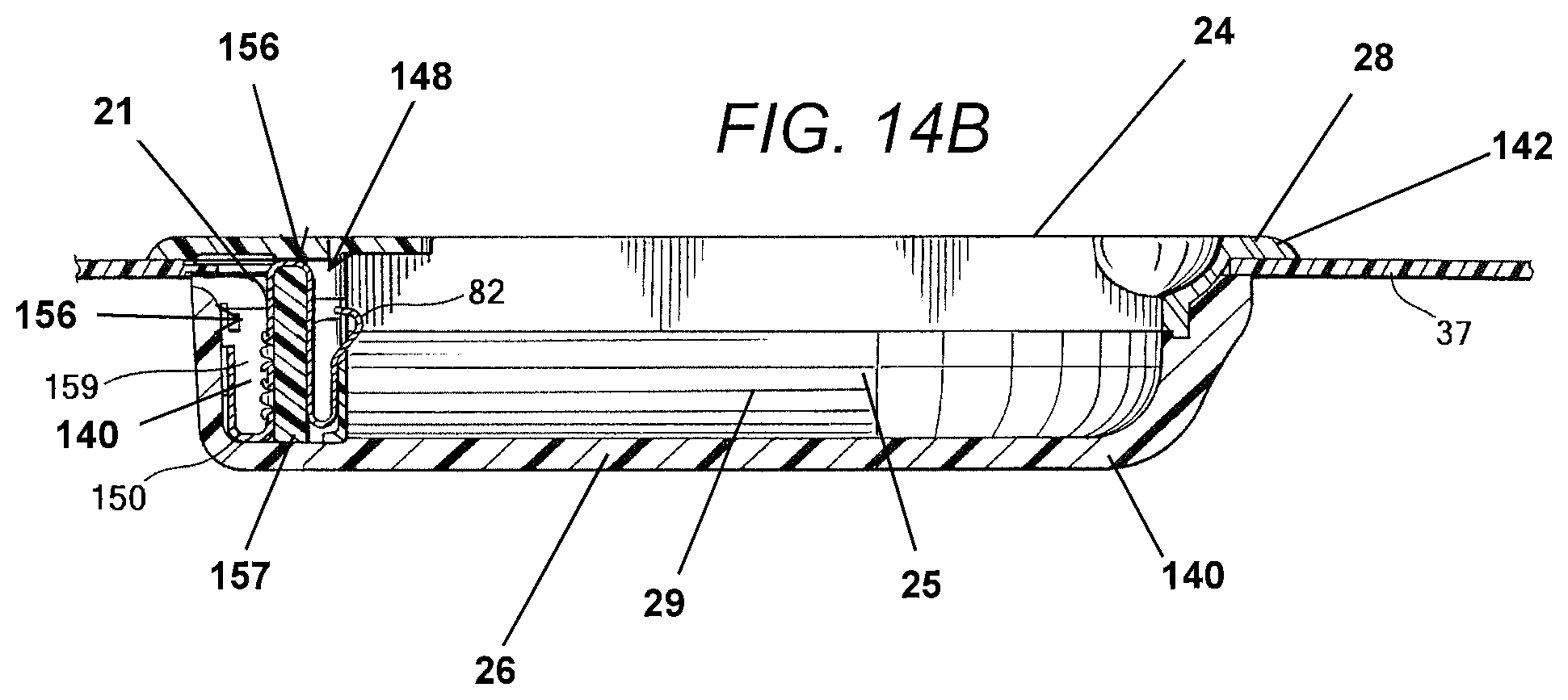
D00013

D00014
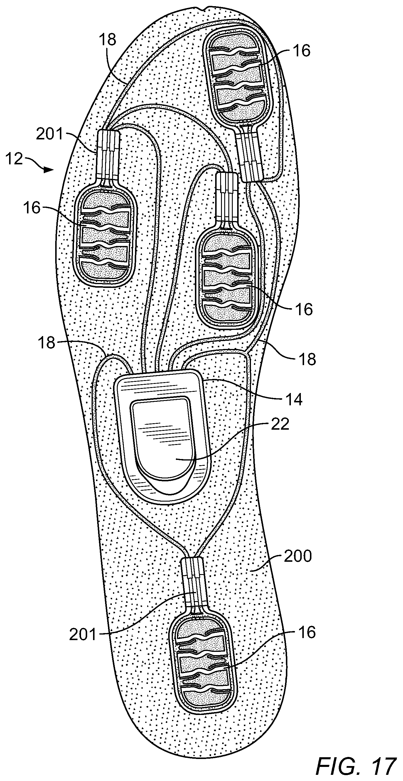
D00015
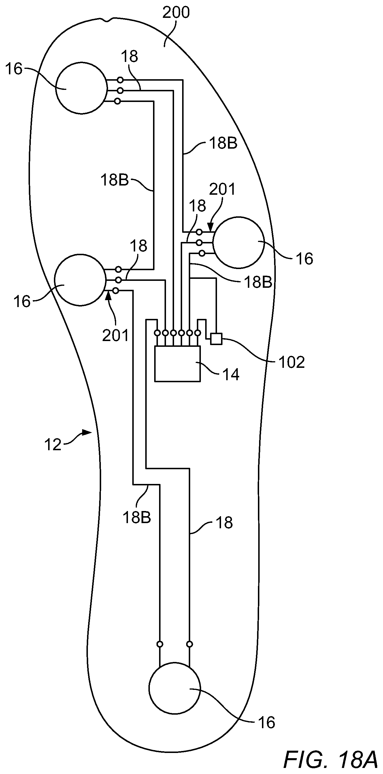
D00016
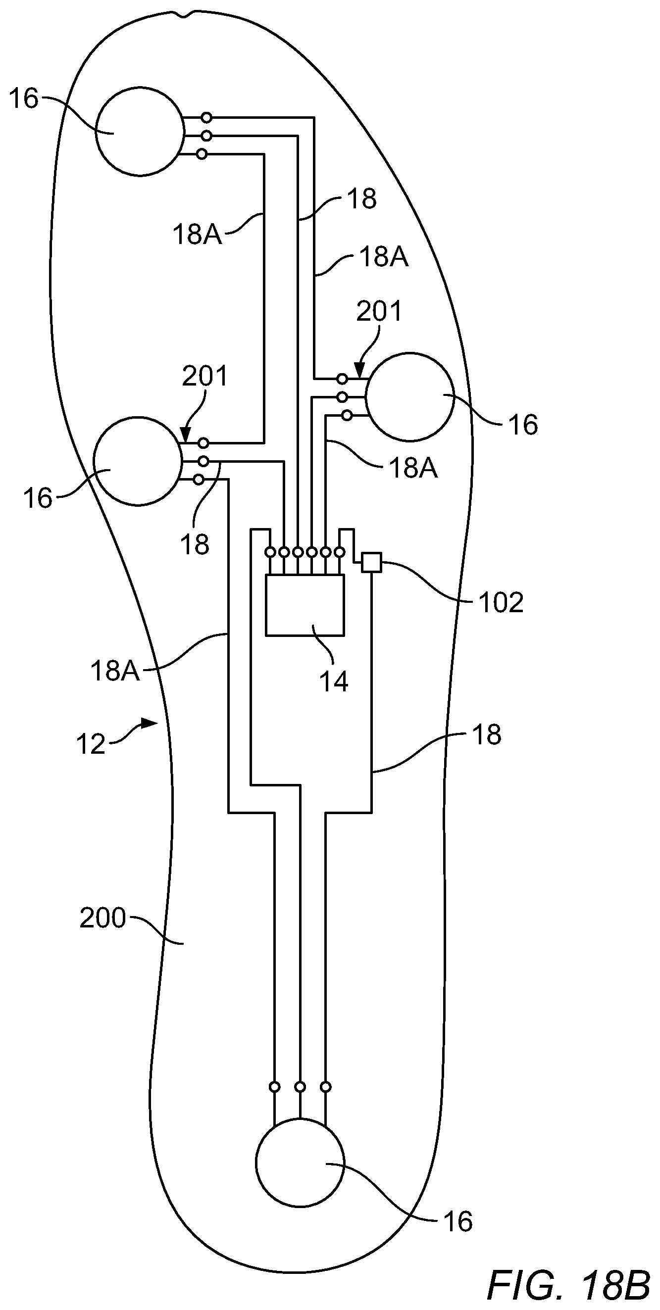
D00017
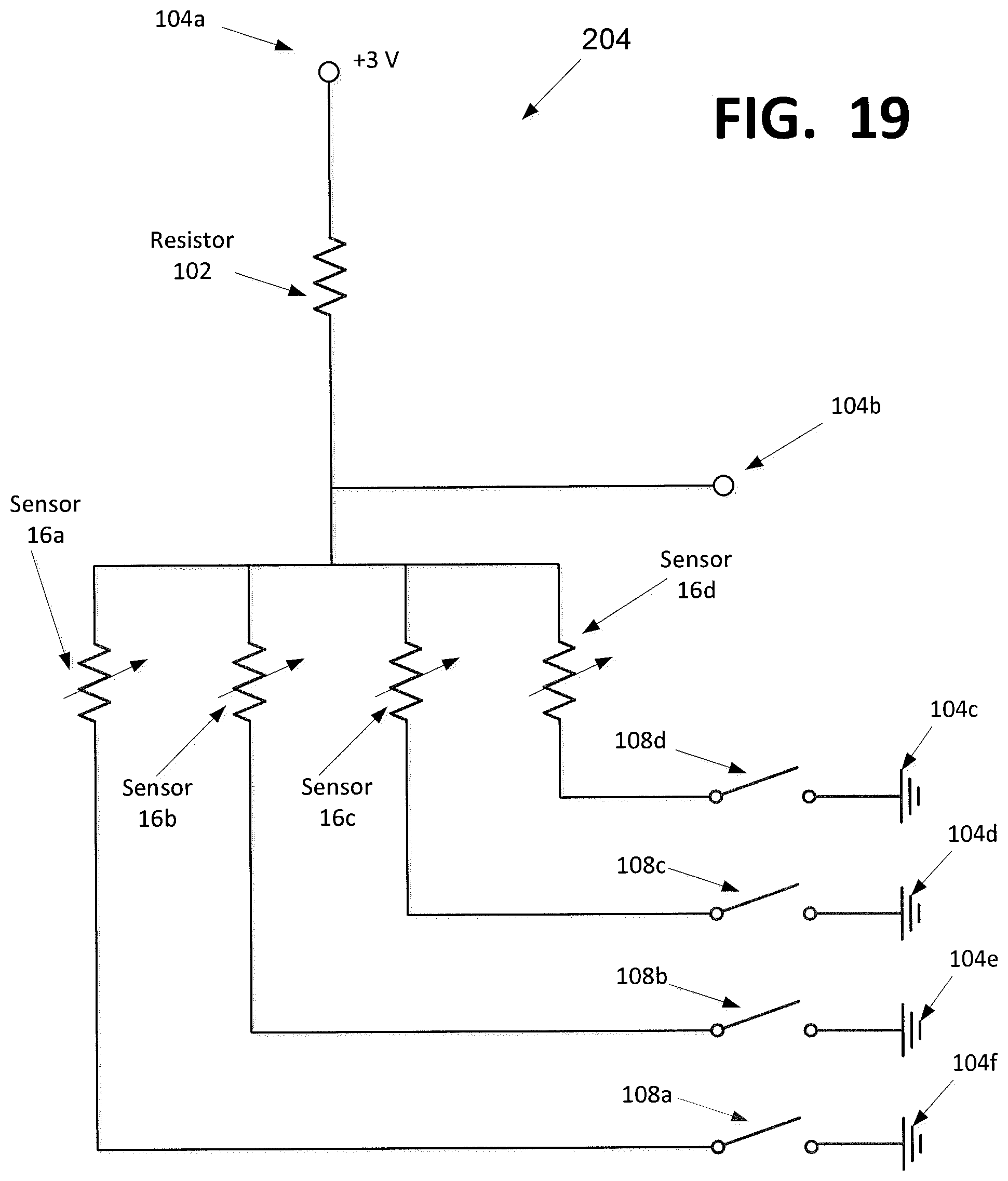
D00018

D00019

D00020

D00021
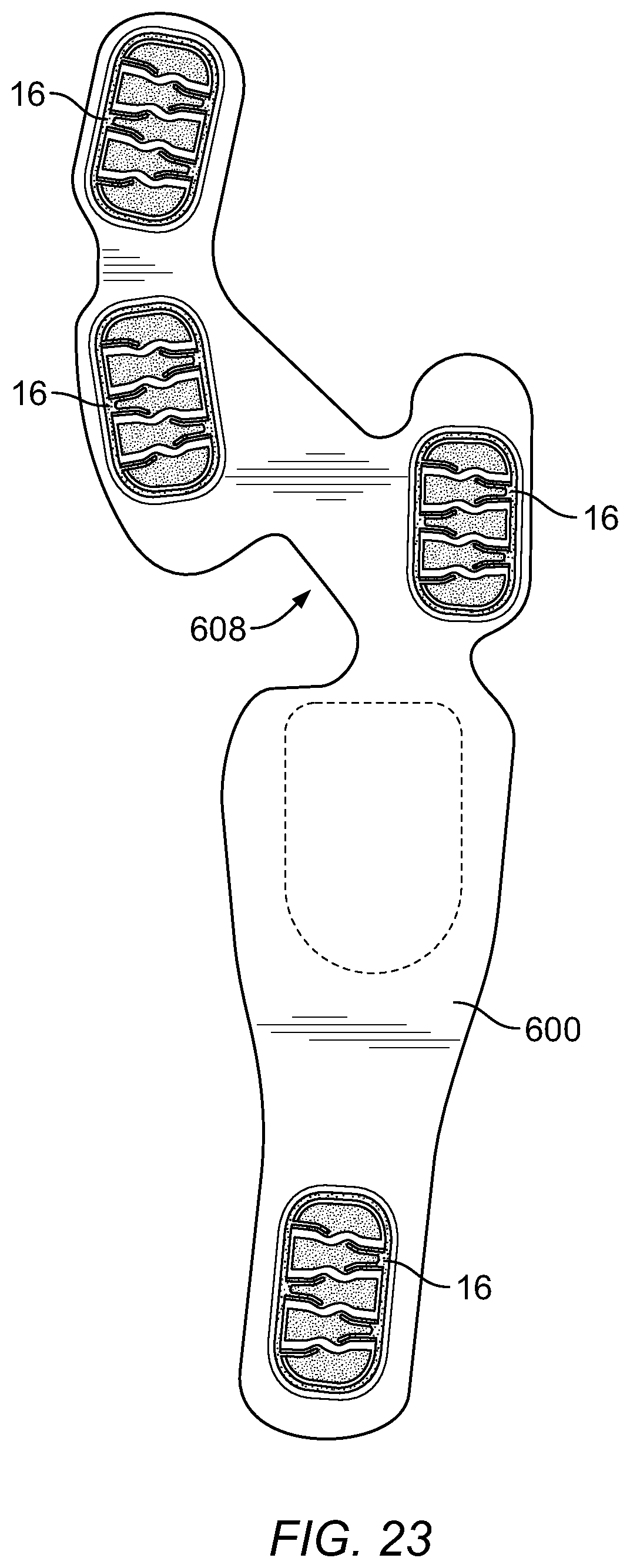
D00022

D00023

D00024
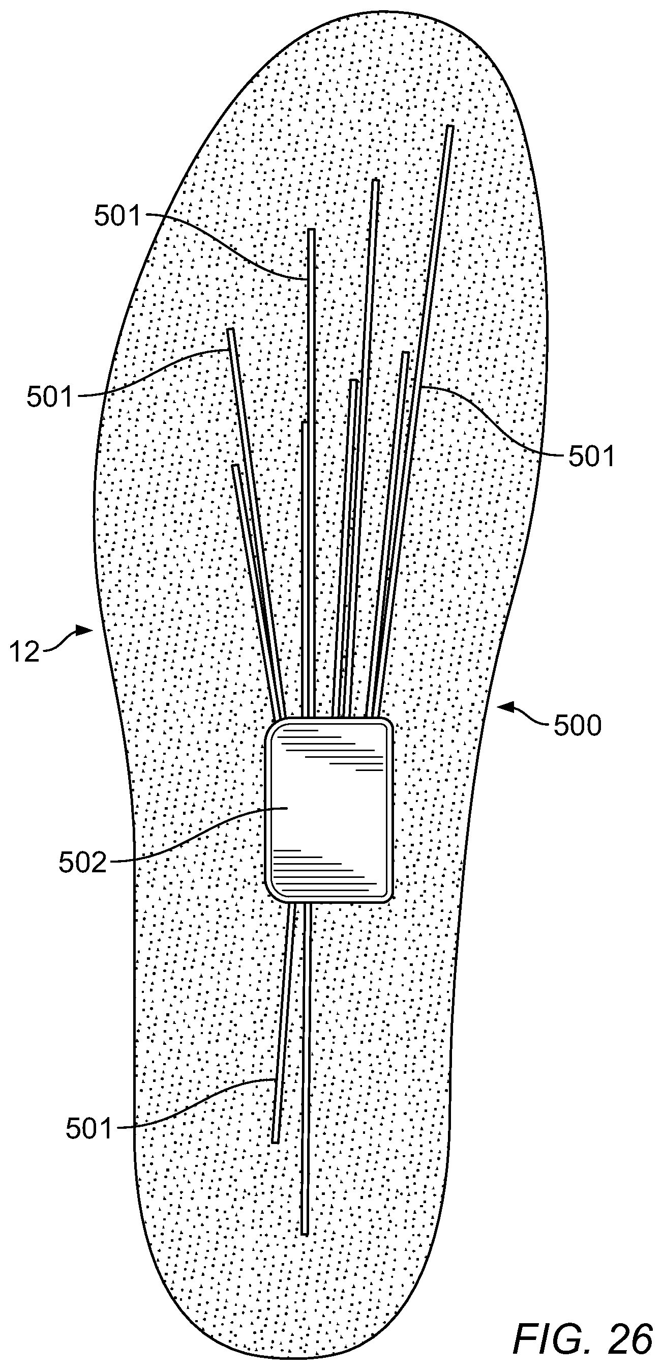
D00025

D00026

XML
uspto.report is an independent third-party trademark research tool that is not affiliated, endorsed, or sponsored by the United States Patent and Trademark Office (USPTO) or any other governmental organization. The information provided by uspto.report is based on publicly available data at the time of writing and is intended for informational purposes only.
While we strive to provide accurate and up-to-date information, we do not guarantee the accuracy, completeness, reliability, or suitability of the information displayed on this site. The use of this site is at your own risk. Any reliance you place on such information is therefore strictly at your own risk.
All official trademark data, including owner information, should be verified by visiting the official USPTO website at www.uspto.gov. This site is not intended to replace professional legal advice and should not be used as a substitute for consulting with a legal professional who is knowledgeable about trademark law.