System and method for providing access to co-located operations data for an electronic display
Newnham , et al. February 2, 2
U.S. patent number 10,908,863 [Application Number 16/508,877] was granted by the patent office on 2021-02-02 for system and method for providing access to co-located operations data for an electronic display. This patent grant is currently assigned to Manufacturing Resources International, Inc.. The grantee listed for this patent is Manufacturing Resources International, Inc.. Invention is credited to Brock Bearchell, Elliot Newnham.


View All Diagrams
| United States Patent | 10,908,863 |
| Newnham , et al. | February 2, 2021 |
System and method for providing access to co-located operations data for an electronic display
Abstract
A system and method for providing access to co-located operations data for a number of electronic display assemblies is provided. A network monitoring center electronically communicates with a number of electronic display assemblies, each comprising sensors measuring operations data, which is stored at a database but electronically partitioned by client identifier. A client identifier is assigned to the operations data. Upon receipt of an operations data request, operations data associated with a client identifier matching a received identifier is summarized in a report which is transmitted to a client device which sent the request.
| Inventors: | Newnham; Elliot (Alpharetta, GA), Bearchell; Brock (Alpharetta, GA) | ||||||||||
|---|---|---|---|---|---|---|---|---|---|---|---|
| Applicant: |
|
||||||||||
| Assignee: | Manufacturing Resources
International, Inc. (Alpharetta, GA) |
||||||||||
| Family ID: | 1000005336545 | ||||||||||
| Appl. No.: | 16/508,877 | ||||||||||
| Filed: | July 11, 2019 |
Prior Publication Data
| Document Identifier | Publication Date | |
|---|---|---|
| US 20200019363 A1 | Jan 16, 2020 | |
Related U.S. Patent Documents
| Application Number | Filing Date | Patent Number | Issue Date | ||
|---|---|---|---|---|---|
| 62697016 | Jul 12, 2018 | ||||
| Current U.S. Class: | 1/1 |
| Current CPC Class: | G06F 3/14 (20130101); H04L 43/06 (20130101) |
| Current International Class: | G06F 3/14 (20060101); H04L 12/26 (20060101) |
References Cited [Referenced By]
U.S. Patent Documents
| 5162785 | November 1992 | Fagard |
| 5351201 | September 1994 | Harshbarger, Jr. et al. |
| 5590831 | January 1997 | Manson et al. |
| 5751346 | May 1998 | Dozier et al. |
| 5786801 | July 1998 | Ichise |
| 5952992 | September 1999 | Helms |
| 6144359 | November 2000 | Grave |
| 6157143 | December 2000 | Bigio et al. |
| 6215411 | April 2001 | Gothard |
| 6222841 | April 2001 | Taniguchi |
| 6259492 | July 2001 | Imoto et al. |
| 6384736 | May 2002 | Gothard |
| 6421694 | July 2002 | Nawaz et al. |
| 6509911 | January 2003 | Shimotono |
| 6546294 | April 2003 | Kelsey et al. |
| 6553336 | April 2003 | Johnson et al. |
| 6556258 | April 2003 | Yoshida et al. |
| 6587525 | July 2003 | Jeong et al. |
| 6753842 | June 2004 | Williams et al. |
| 6771795 | August 2004 | Isnardi |
| 6812851 | November 2004 | Dukach et al. |
| 6850209 | February 2005 | Mankins et al. |
| 6968375 | November 2005 | Brown |
| 7038186 | May 2006 | De Brabander et al. |
| 7064672 | June 2006 | Gothard |
| 7319862 | January 2008 | Lincoln et al. |
| 7330002 | February 2008 | Joung |
| 7369058 | May 2008 | Gothard |
| 7380265 | May 2008 | Jensen et al. |
| 7391317 | June 2008 | Abraham et al. |
| 7451332 | November 2008 | Culbert et al. |
| 7474294 | January 2009 | Leo et al. |
| 7577458 | August 2009 | Lin |
| 7581094 | August 2009 | Apostolopoulos et al. |
| 7595785 | September 2009 | Jang |
| 7612278 | November 2009 | Sitrick et al. |
| 7614065 | November 2009 | Weissmueller, Jr. et al. |
| 7636927 | December 2009 | Zigmond et al. |
| 7675862 | March 2010 | Pham et al. |
| 7751813 | July 2010 | Varanda |
| 7764280 | July 2010 | Shiina |
| 7774633 | August 2010 | Harrenstien et al. |
| 7795821 | September 2010 | Jun |
| 7949893 | May 2011 | Knaus et al. |
| 8212921 | July 2012 | Yun |
| 8218812 | July 2012 | Sugimoto et al. |
| 8248203 | August 2012 | Hanwright et al. |
| 8441574 | May 2013 | Dunn et al. |
| 8601252 | December 2013 | Mendelow et al. |
| 8689343 | April 2014 | De Laet |
| 8983385 | March 2015 | Macholz |
| 9026686 | May 2015 | Dunn et al. |
| 9812047 | November 2017 | Schuch et al. |
| 10325536 | June 2019 | Schuch et al. |
| 10593175 | March 2020 | Jennings |
| 2002/0019933 | February 2002 | Friedman et al. |
| 2002/0026354 | February 2002 | Shoji et al. |
| 2002/0112026 | August 2002 | Fridman et al. |
| 2002/0120721 | August 2002 | Eilers et al. |
| 2002/0147648 | October 2002 | Fadden et al. |
| 2002/0152425 | October 2002 | Chaiken et al. |
| 2002/0163513 | November 2002 | Tsuji |
| 2002/0163916 | November 2002 | Oskouy et al. |
| 2002/0164962 | November 2002 | Mankins et al. |
| 2002/0190972 | December 2002 | Ven de Van |
| 2002/0194365 | December 2002 | Jammes |
| 2002/0194609 | December 2002 | Tran |
| 2003/0031128 | February 2003 | Kim et al. |
| 2003/0039312 | February 2003 | Horowitz et al. |
| 2003/0061316 | March 2003 | Blair et al. |
| 2003/0097497 | May 2003 | Esakov |
| 2003/0098881 | May 2003 | Nolte et al. |
| 2003/0115591 | June 2003 | Weissmueller, Jr. et al. |
| 2003/0117714 | June 2003 | Nakamura et al. |
| 2003/0161354 | August 2003 | Bader et al. |
| 2003/0177269 | September 2003 | Robinson et al. |
| 2003/0192060 | October 2003 | Levy |
| 2003/0196208 | October 2003 | Jacobson |
| 2003/0214242 | November 2003 | Berg-johansen |
| 2003/0230991 | December 2003 | Muthu et al. |
| 2004/0036697 | February 2004 | Kim et al. |
| 2004/0138840 | July 2004 | Wolfe |
| 2004/0158872 | August 2004 | Kobayashi |
| 2004/0194131 | September 2004 | Ellis et al. |
| 2004/0243940 | December 2004 | Lee et al. |
| 2004/0252400 | December 2004 | Blank et al. |
| 2004/0253947 | December 2004 | Phillips et al. |
| 2005/0033840 | February 2005 | Nisani et al. |
| 2005/0070335 | March 2005 | Jitsuishi et al. |
| 2005/0071252 | March 2005 | Henning et al. |
| 2005/0073518 | April 2005 | Bontempi |
| 2005/0088984 | April 2005 | Chin et al. |
| 2005/0123001 | June 2005 | Craven et al. |
| 2005/0132036 | June 2005 | Jang et al. |
| 2005/0179554 | August 2005 | Lu |
| 2005/0184983 | August 2005 | Brabander et al. |
| 2005/0216939 | September 2005 | Corbin |
| 2005/0231457 | October 2005 | Yamamoto et al. |
| 2005/0267943 | December 2005 | Castaldi et al. |
| 2005/0289061 | December 2005 | Kulakowski et al. |
| 2005/0289588 | December 2005 | Kinnear |
| 2006/0007107 | January 2006 | Ferguson |
| 2006/0022616 | February 2006 | Furukawa et al. |
| 2006/0150222 | July 2006 | McCafferty et al. |
| 2006/0160614 | July 2006 | Walker et al. |
| 2006/0269216 | November 2006 | Wiemeyer et al. |
| 2007/0039028 | February 2007 | Bar |
| 2007/0154060 | July 2007 | Sun |
| 2007/0157260 | July 2007 | Walker |
| 2007/0168539 | July 2007 | Day |
| 2007/0200513 | August 2007 | Ha et al. |
| 2007/0214812 | September 2007 | Wagner et al. |
| 2007/0237636 | October 2007 | Hsu |
| 2007/0268241 | November 2007 | Nitta et al. |
| 2007/0273519 | November 2007 | Ichikawa et al. |
| 2007/0274400 | November 2007 | Murai et al. |
| 2007/0286107 | December 2007 | Singh et al. |
| 2007/0291198 | December 2007 | Shen |
| 2008/0008471 | January 2008 | Dress |
| 2008/0019147 | January 2008 | Erchak et al. |
| 2008/0024268 | January 2008 | Wong et al. |
| 2008/0034205 | February 2008 | Alain et al. |
| 2008/0037466 | February 2008 | Ngo et al. |
| 2008/0037783 | February 2008 | Kim et al. |
| 2008/0055297 | March 2008 | Park |
| 2008/0096559 | April 2008 | Phillips et al. |
| 2008/0104631 | May 2008 | Krock et al. |
| 2008/0111958 | May 2008 | Kleverman et al. |
| 2008/0112601 | May 2008 | Warp |
| 2008/0136770 | June 2008 | Peker et al. |
| 2008/0163291 | July 2008 | Fishman et al. |
| 2008/0185976 | August 2008 | Dickey et al. |
| 2008/0218501 | September 2008 | Diamond |
| 2008/0246871 | October 2008 | Kupper et al. |
| 2008/0266554 | October 2008 | Sekine et al. |
| 2008/0267328 | October 2008 | Ianni et al. |
| 2008/0278099 | November 2008 | Bergfors et al. |
| 2008/0281165 | November 2008 | Rai et al. |
| 2008/0303918 | December 2008 | Keithley |
| 2008/0313691 | December 2008 | Cholas et al. |
| 2009/0009997 | January 2009 | Sanfilippo et al. |
| 2009/0015400 | January 2009 | Breed |
| 2009/0036190 | February 2009 | Brosnan et al. |
| 2009/0079416 | March 2009 | Vinden et al. |
| 2009/0104989 | April 2009 | Williams et al. |
| 2009/0129556 | May 2009 | Ahn |
| 2009/0152445 | June 2009 | Gardner, Jr. |
| 2009/0164615 | June 2009 | Akkanen |
| 2009/0273568 | November 2009 | Milner |
| 2009/0315867 | December 2009 | Sakamoto et al. |
| 2010/0017526 | January 2010 | Jagannath et al. |
| 2010/0037274 | February 2010 | Meuninck et al. |
| 2010/0060550 | March 2010 | McGinn et al. |
| 2010/0083305 | April 2010 | Acharya et al. |
| 2010/0149567 | June 2010 | Kanazawa et al. |
| 2010/0177157 | July 2010 | Stephens et al. |
| 2010/0177158 | July 2010 | Walter |
| 2010/0177750 | July 2010 | Essinger et al. |
| 2010/0198983 | August 2010 | Monroe et al. |
| 2010/0231563 | September 2010 | Dunn et al. |
| 2010/0237697 | September 2010 | Dunn et al. |
| 2010/0238299 | September 2010 | Dunn et al. |
| 2010/0299556 | November 2010 | Taylor et al. |
| 2011/0019636 | January 2011 | Fukuoka et al. |
| 2011/0047567 | February 2011 | Zigmond et al. |
| 2011/0078536 | March 2011 | Han et al. |
| 2011/0283199 | November 2011 | Schuch |
| 2012/0105424 | May 2012 | Lee et al. |
| 2012/0203872 | August 2012 | Luby et al. |
| 2012/0302343 | November 2012 | Hurst et al. |
| 2012/0308191 | December 2012 | Chung et al. |
| 2013/0162908 | June 2013 | Son et al. |
| 2014/0002747 | January 2014 | Macholz |
| 2015/0250021 | September 2015 | Stice et al. |
| 2016/0034240 | February 2016 | Kreiner et al. |
| 2017/0075777 | March 2017 | Dunn et al. |
| 2017/0163519 | June 2017 | Bowers et al. |
| 2017/0315886 | November 2017 | Helmick et al. |
| 2018/0061297 | March 2018 | Schuch et al. |
| 2018/0181091 | June 2018 | Funk |
| 203277867 | Nov 2013 | CN | |||
| 0313331 | Feb 1994 | EP | |||
| 1821538 | Aug 2007 | EP | |||
| 2351369 | Aug 2011 | EP | |||
| 2396964 | Dec 2011 | EP | |||
| 3347793 | Jul 2018 | EP | |||
| 61-234690 | Oct 1986 | JP | |||
| 61-251901 | Nov 1986 | JP | |||
| 7-74224 | Mar 1995 | JP | |||
| 2000122575 | Apr 2000 | JP | |||
| 2002064842 | Feb 2002 | JP | |||
| 2002209230 | Jul 2002 | JP | |||
| 2005-211449 | Aug 2005 | JP | |||
| 2005-211451 | Aug 2005 | JP | |||
| 2005236469 | Sep 2005 | JP | |||
| 2005333568 | Dec 2005 | JP | |||
| 2010282109 | Dec 2010 | JP | |||
| 2018537876 | Dec 2018 | JP | |||
| WO9608892 | Mar 1996 | WO | |||
| WO2008050402 | May 2008 | WO | |||
| WO2011106683 | Sep 2011 | WO | |||
| WO2017044952 | Mar 2017 | WO | |||
Other References
|
Photo Research, PR-650 SpectraScan Colorimeter, 1999, 2 Pages. cited by applicant . Texas Advanced Optoelectronic Solutions, TCS230 Programmable Color Light-to-Frequency Converter, 2007, 12 Pages. cited by applicant . Don Methven, Wireless Video Streaming: An Overview, Nov. 16, 2002, 7 Pages. cited by applicant . Outdoorlink, Inc., SmartLink One, One Relay, http://smartlinkcontrol.com/billboard/one-relay/, retrieved Apr. 17, 2019, 2007-16, 6 pages. cited by applicant . Outdoorlink, Inc., SmartLink Website User Manual, http://smartlink.outdoorlinkinc.com/docs/SmartLinkWebsiteUserManual.pdf, 2017, 33 pages. cited by applicant . Outdoorlink, Inc., SmartLink One Out of Home Media Controller, 2016, 1 page. cited by applicant. |
Primary Examiner: Edwards; Mark
Attorney, Agent or Firm: Standley Law Group LLP Standley; Jeffrey S. Smith; Adam J.
Parent Case Text
CROSS-REFERENCE TO RELATED APPLICATION
This application claims the benefit of U.S. Provisional Application No. 62/697,016 filed Jul. 12, 2018, the disclosure of which is hereby incorporated by reference as if fully restated herein.
Claims
What is claimed is:
1. A system for providing access to co-located operations data for a number of electronic display assemblies for a number of different clients, said system comprising: a network monitoring center in electronic communication with each of the number of electronic display assemblies, wherein each of the electronic display assemblies comprise one or more sensors configured to measure operations data for the respective electronic display assembly; a number of client devices in electronic communication with the network monitoring center; a database at the network operations center configured to receive operations data from each of the electronic display assemblies; and at least one electronic storage device located at the network operations center and comprising software instructions, which when executed, configure at least one processor to: store operations data received from each of the electronic display assemblies at the database; assign a client identifier to each portion of the received operations data, including at least: assign a first client identifier to a first portion of the received operations data for a first one of the electronic display assemblies: assign a second client identifier to a second portion of the received operations data for the first one of the electronic display assemblies; electronically partition the stored operations data by assigned client identifier; monitor for operations data requests from any of the number of client devices, wherein said operations data requests comprise one of said client identifiers; upon receipt of an operations data request, query the database for operations data associated with the received client identifier; summarize the operations data retrieved from the database into a summary report; and transmit the summary report to the client device which sent the operations data request.
2. The system of claim 1 wherein: a particular one of said electronic display assemblies is associated with a particular one of said client identifiers; and the particular client identifier associated with the particular electronic display assembly is automatically assigned to all operations data received from said particular electronic display assembly.
3. The system of claim 1 wherein: a particular client identifier is automatically assigned to all operations data received from any of the number of electronic display assemblies scheduled to display a particular image.
4. The system of claim 1 wherein: electronic communication between the network operations center and each of the electronic display assemblies is made by way of a network and a network connectivity device provided at the network operations center and each of the electronic display assemblies.
5. The system of claim 1 wherein: said operations data comprises fan speed, ambient temperature readings, internal temperature readings, ambient light levels, backlight levels, power consumption information, air quality readings, and ambient weather conditions.
6. The system of claim 1 wherein: said operations data comprises one or more images displayed at each of said electronic display assemblies.
7. The system of claim 1 wherein: said at least one electronic storage device comprises additional software instructions, which when executed, configure the at least one processor to verify received login information, wherein said login information includes one of said client identifiers.
8. The system of claim 7 wherein: said at least one electronic storage device comprises additional software instructions, which when executed, configure the at least one processor to: receive updated operations instructions, wherein said updated operations instructions are associated with the client identifier provided with said login information; and transmit said updated operations instructions to the electronic display assembly associated with the client identifier provided with said login information.
9. The system of claim 8 wherein: said operations instructions comprise fan speed instructions and backlight level instructions.
10. The system of claim 7 wherein: said operations data comprises status information; and said summary report comprises a listing of, and status information for, each electronic display assembly associated with the client identifier provided with said login information.
11. The system of claim 10 wherein: said operations comprises event information; and said summary report comprises a listing of events experienced within a predetermined time period for each of said electronic display assemblies.
12. The system of claim 11 wherein: said operations data comprises fan speed, ambient temperature readings, internal temperature readings, ambient light levels, and backlight levels; and said summary report comprises a visual depiction of said fan speed, ambient temperature readings, internal temperature readings, ambient light levels, and backlight levels.
13. The system of claim 12 wherein: said visual depiction comprises a line graph.
14. The system of claim 12 wherein: said operations data comprises air quality readings and ambient weather conditions; and said summary report comprises said air quality readings and ambient weather conditions.
15. A method for providing access to co-located operations data for a number of electronic display assemblies comprising: placing a network monitoring center in electronic communication with each of the number of electronic display assemblies; measuring, by way of one or more sensors at each of the electronic display assemblies, operations data at each respective electronic display assembly; placing a number of client devices in electronic communication with the network monitoring center; storing, at a database located at the network operations center, operations data received from each of the electronic display assemblies; assigning a client identifier to each portion of the received operations data; electronically partitioning the stored operations data by assigned client identifier; receiving an operations data requests from one of the client devices, wherein said operations data requests comprise an identifier; querying the database for operations data associated with a client identifier matching the received identifier; generating a summary report comprising the operations data retrieved from the database; and transmitting the summary report to the client device which sent the operations data request; verifying received login information, wherein said login information includes one of said client identifiers; receiving, at the network monitoring center, updated operations instructions, wherein said updated operations instructions are associated with the client identifier provided with said login information; and transmitting said updated operations instructions to the electronic display assembly associated with the client identifier provided with said login information.
16. The method of claim 15 wherein: the step of assigning a client identifier to each portion of the received operations data comprises the sub-steps of: assigning one of the client identifiers to each of the electronic display assemblies; and associating operations data received from a particular electronic display assembly with the client identifier assigned to the respective electronic display assembly.
17. The method of claim 15 wherein: the step of assigning a client identifier to each portion of the received operations data comprises the sub-steps of: assigning one of the client identifiers to each image scheduled to be displayed on one or more of the electronic display assemblies; and associating operations data received from all of the electronic display assemblies scheduled to display a particular image with the client identifier assigned to the respective image.
18. The method of claim 15 wherein: said operations data comprises fan speed, ambient temperature readings, internal temperature readings, ambient light levels, backlight levels, and power consumption information; and said summary report comprises a graph comprising fan speed, ambient temperature readings, internal temperature readings, ambient light levels, backlight levels, and power consumption information over a predetermined period of time.
19. A system for providing access to co-located operations data for a number of electronic display assemblies comprising: a number of client devices, wherein each of said client devices is a personal electronic device; a network monitoring center in electronic communication with each of the number of electronic display assemblies and each of the client devices by way of a network, wherein each of the electronic display assemblies comprise one or more sensors configured to measure operations data for the respective electronic display assembly; a database at the network operations center configured to receive operations data from each of the electronic display assemblies; and an electronic storage device located at the network operations center and comprising software instructions, which when executed, configure a processor to: assign a unique, alphanumeric client identifier to each electronic display assembly; sequentially request operations data from each of the electronic display assemblies; associate operations data received from a particular electronic display with the client identifier assigned to the respective electronic display assembly; co-locate, but electronically partition, said received operations data based on the client identifier associated with said operations data; upon receipt of an operations data request from one of the client devices, query the database for operations data associated with a client identifier matching an identifier received in the operations data request; generate a summary report comprising the operations data retrieved from the database; transmit the summary report to the client device which sent the operations data request; and upon receipt of operations instructions associated with one of said client identifiers, transmit said operations instructions to each electronic display assembly associated with a client identifier received with the operations instructions; wherein said operations data comprises fan speed, ambient temperature readings, internal temperature readings, ambient light levels, backlight levels, power consumption information, air quality readings, and ambient weather conditions; wherein said operations instructions comprise fan speed instructions and backlight level instructions; wherein said summary report comprises a line chart indicating fan speed, ambient temperature readings, internal temperature readings, ambient light levels, backlight levels, power consumption information, air quality readings, and ambient weather conditions over a predetermined period of time.
20. The system of claim 1 wherein: said at least one electronic storage device comprises additional software instructions, which when executed, configure the at least one processor to: assign the first client identifier to a third portion of the received operations data for a second one of the electronic display assemblies; and assign the second client identifier to a fourth portion of the received operations data for a third first one of the electronic display assemblies.
21. A system for providing access to co-located operations data for a number of electronic display assemblies, said system comprising: a network monitoring center in electronic communication with each of the number of electronic display assemblies, wherein each of the electronic display assemblies comprise one or more sensors configured to measure operations data for the respective electronic display assembly; a number of client devices in electronic communication with the network monitoring center; one or more databases at the network operations center configured to receive operations data from each of the electronic display assemblies; and one or more electronic storage devices located at the network operations center and comprising software instructions, which when executed, configure one or more processors to: store operations data received from each of the electronic display assemblies at the one or more databases; assign a client identifier to each portion of the received operations data; electronically partition the stored operations data by assigned client identifier; monitor for operations data requests from any of the number of client devices, wherein said operations data requests comprise one of said client identifiers; verify received login information, wherein said login information includes one of said client identifiers; upon receipt of an operations data request, query the one or more databases for operations data associated with the received client identifier; summarize the operations data retrieved from the one or more databases into a summary report; and transmit the summary report to the client device which sent the operations data request.
Description
TECHNICAL FIELD
Exemplary embodiments relate generally to a system and method for providing access to co-located operations data, particularly with regards to operation of an electronic display assembly.
BACKGROUND AND SUMMARY OF THE INVENTION
The use of electronic displays has increased in recent years. Beyond personal use, these electronic displays are sometimes placed in an enclosure, which may be ruggedized, for both indoor and/or outdoor use. For example, without limitation, such display assemblies may be placed outdoors, such as on sidewalks or on the tops of vehicles to name some examples, to display advertisements or other information. Oftentimes these display assemblies are associated with other electronic equipment to provide features such as, but not limited to, video conferencing, web browsing, way finding, image capture, emergency notification, and the like. It is desirable to provide owners, manufactures, operators, renters, or the like of such display assemblies with access to operations data regarding the status and operation of such display assemblies. Furthermore, these display assemblies consume a significant amount of power during operation. A significant amount of the energy consumption of such display assemblies comes from operation of the backlight. Particularly as the use of such display assemblies has increased, it is desirable that such operations data include data regarding the energy consumption of the display, including but not limited to, status and operation of the backlight. Such operations data may be stored and presented to display owners and other relevant parties such that energy consumption and reliability may be tracked. Certain operations parameters may be adjusted in response to the presented data. For example, without limitation, backlight levels may be adjusted downward to reduce energy consumption or maintenance frequencies may be increased in response to reported display assembly downtime.
However, for many such display assemblies, multiple parties may have an interest in the operations data. For example, a display assembly manufacturer may have an interest in monitoring its tens, hundreds, thousands, tens of thousands, etc. of display assemblies. Each owner or renter of one or more such display assemblies might likewise have an interest in monitoring the display assemblies it owns. While the manufacturer may already have access to this operations data, the operations data may include data for all owners or renters. Thus, the operations data may be co-located with operations data for other owners or renters. Allowing complete access to such data may create privacy concerns. However, individual storage of each client's information would potentially require multiple storage devices, increasing complexity and expense. Therefore, what is needed is a system and method for providing access to co-located operations data for a display assembly.
The present disclosures provide a system and method for providing access to co-located operations data for a display assembly. The system may comprise one or more client devices in communication with a centralized monitoring center via a network. Multiple display assemblies may likewise be in communication with the monitoring center via the network. In exemplary embodiments, each display assembly comprises one or more electronic displays and other electronic components for operation of the display assembly in electrical connection with a display controller. The display controller may likewise be in electrical connection with a network interface device. The network interface device may likewise be in communication with the centralized monitoring center via the network.
Operations data may be continually gathered and transmitted to the central monitoring center for storage. The received operations data may be processed. Such processing may determine which client(s) are associated with the operations data and what the operations data represents. The operations data may be summarized and presented in a visual depiction. Upon receipt of a client request for operations information, client specific information may be retrieved and presented to the client in the visual depiction. In other exemplary embodiments, upon login, a client may be permitted to remotely operate or modify display assemblies associated with the client.
BRIEF DESCRIPTION OF THE DRAWINGS
In addition to the features mentioned above, other aspects of the present invention will be readily apparent from the following descriptions of the drawings and exemplary embodiments, wherein like reference numerals across the several views refer to identical or equivalent features, and wherein:
FIG. 1 is a simplified plan view of an exemplary system;
FIG. 2 is a detailed view of an exemplary display assembly of FIG. 1;
FIG. 3 is a detailed view of an exemplary monitoring center of FIG. 1;
FIG. 4 is a detailed view of an exemplary client device of FIG. 1;
FIG. 5 is a flow chart of exemplary logic for use with the system of FIG. 1;
FIG. 6 is a flow chart of other exemplary logic for use with the system of FIG. 1;
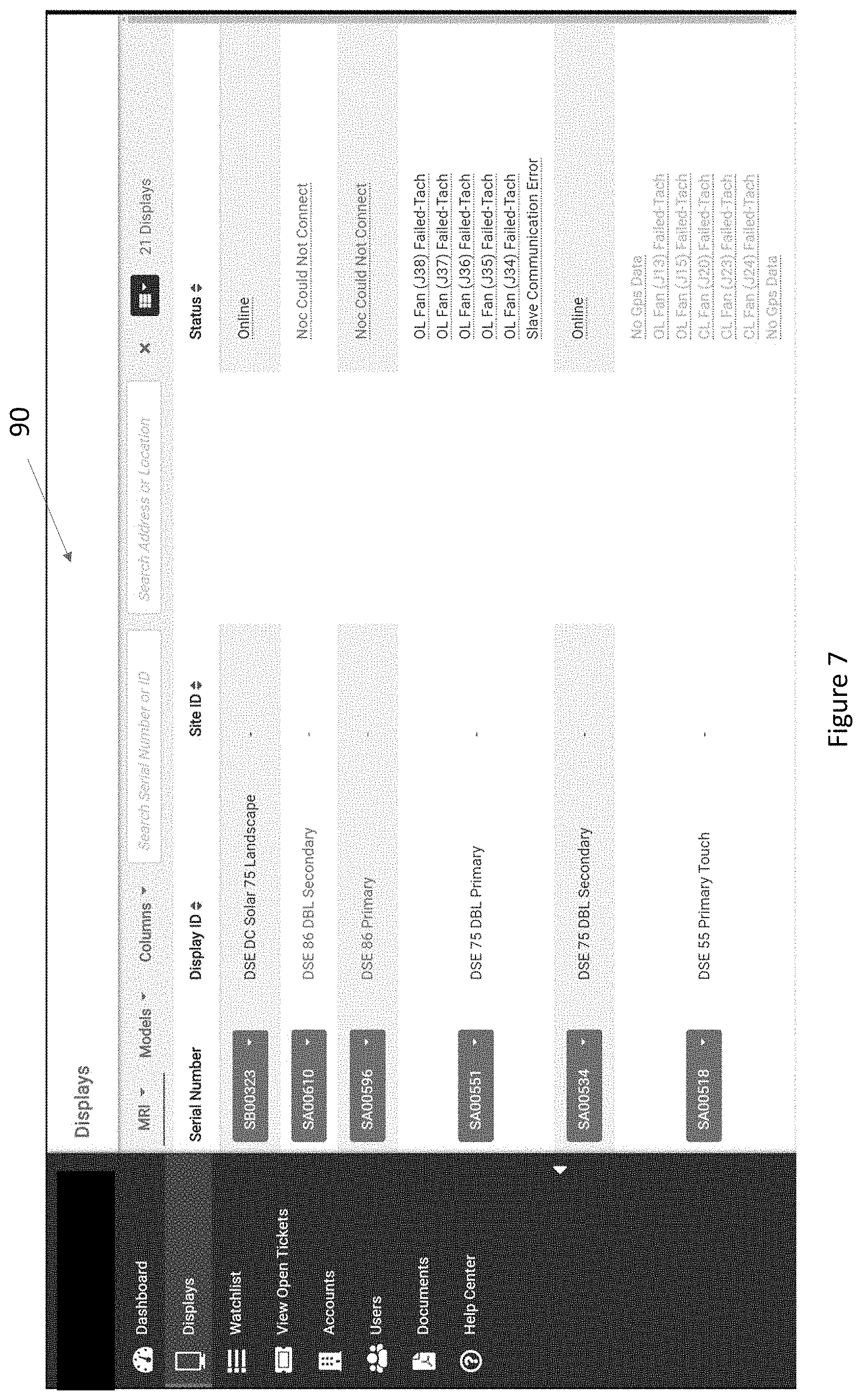
FIG. 7 is an exemplary user interface for use with the system of FIG. 1;
FIG. 8 is another exemplary user interface for use with the system of FIG. 1;
FIG. 9 is another exemplary user interface for use with the system of FIG. 1;
FIG. 10 is another exemplary user interface for use with the system of FIG. 1; and
FIG. 11 is another exemplary user interface for use with the system of FIG. 1.
DETAILED DESCRIPTION OF EXEMPLARY EMBODIMENT(S)
Various embodiments of the present invention will now be described in detail with reference to the accompanying drawings. In the following description, specific details such as detailed configuration and components are merely provided to assist the overall understanding of these embodiments of the present invention. Therefore, it should be apparent to those skilled in the art that various changes and modifications of the embodiments described herein can be made without departing from the scope and spirit of the present invention. In addition, descriptions of well-known functions and constructions are omitted for clarity and conciseness.
Embodiments of the invention are described herein with reference to illustrations of idealized embodiments (and intermediate structures) of the invention. As such, variations from the shapes of the illustrations as a result, for example, of manufacturing techniques and/or tolerances, are to be expected. Thus, embodiments of the invention should not be construed as limited to the particular shapes of regions illustrated herein but are to include deviations in shapes that result, for example, from manufacturing.
FIG. 1 is a simplified block diagram of an exemplary system. A number of display assemblies 30 may be in communication with a monitoring center 20. Similarly, a number of client devices 10 may be in communication with the monitoring center 20. The display assemblies 30 may be located remote from the monitoring center 20. Likewise, the client devices 10 may be located remote from the monitoring center 20. The communication between the display assemblies 30, the monitoring center 20, and the client devices 10 may be made by way of a network 80. The network 80 may be any network such as a cellular network, internet, intranet, world wide web, or the like. The network 80 between the client devices 10 and the monitoring center 20 may be the same or may be different from the network 80 between the monitoring center 20 and the display assemblies 30.
Each of the display assemblies 30 may be any kind of display assembly 30, such as but not limited to, a free-standing display kiosk configured for placement on a sidewalk, a wall-mounted display unit, a vehicle topper unit, or the like. Each of the client devices 10 may be a personal electronic device such as, but not limited to, a smartphone, tablet, smartwatch, laptop, desktop computer, some combination thereof, or the like.
FIG. 2 is a detailed view of an exemplary display assembly 30 of FIG. 1. Each display assembly 30 may comprise one or more electronic displays 70 in electrical connection with a display controller 50. Each electronic display 70 may comprise a backlight for illuminating the electronic display 70. The electronic display 70 may comprise one or more a liquid crystal displays, light emitting diode ("LED") displays, organic LED displays, plasma displays, some combination thereof, or the like. One or more of the electronic displays 70 may comprise touch capabilities. The backlight may be comprised of a number of LEDs arranged in a directly backlit, edge-lit, or other orientation.
In exemplary embodiments, the display controller 50 may be in electrical connection with other components 60 for operating the display assembly 30. Such components 60 may include, but are not limited to, fans, temperature sensors, light sensors, fan speed sensors, power consumption, air quality sensors, weather sensors, other sensors, telephone equipment, video conferencing equipment, VOIP equipment, touch screens, camera, microphones, emergency notification devices, processors, electronic storage devices, wayfinding equipment, location detection devices, video players, proof of play devices, and the like. Any number, combination, and/or type of components are contemplated.
The display controller 50 may be configured to gather operations data from the electronic display 70. The display controller 50 may, alternatively or additionally, be configured to gather operations data from the components 60. Such operations data may include, but is not limited to, proof of play data, fan speed data, temperature data, humidity data, power consumption data, ambient light data, weather data, backlight data, electronic display data, status data, emergency notification data, air quality data, sensor readings, camera images or video recordings, microphone audio recordings, use history, and the like. The operations data for multiple clients may be co-located at the electronic storage device 52 located at the display assembly 30. Portions of the operations data may be associated with one or more client identifiers. For example, without limitation, operations data associated with a particular image displayed on the electronic display 70 may be associated with a particular client identifier. Alternatively, or in addition, all operations data originating from one or more display assemblies 30 may be associated with one or more client identifiers. This may permit for specific clients to access and retrieve only the operations data associated with the particular client--permitting the co-location of such operations data while maintaining privacy. The association with a client identifier may be performed at the display assembly 30 or at the monitoring center 20. The client identifiers may be, without limitation, unique alphanumeric serial numbers.
The display controller 50 may be in electrical communication with a network connection device 40. The network connection device 40 may be configured to transmit information to the monitoring center 20, including but not limited to, the operations data. In exemplary embodiments, the network connection device 40 may likewise be configured to receive information from the monitoring center 20, including but not limited to, operation instructions. Such operations instructions may comprise remote login capabilities, remote viewing, fan speed instructions, backlight adjustment instructions, video or image files for display on the electronic displays 70, some combination thereof, or other instructions for operation of the display assembly 30. The network connection device 40 may transmit and/or receive such information by way of the network 80.
The display controller 50 may comprise an electronic storage device 52 for storing the operations data and/or operations instructions. The display controller 50 may also comprise a processor 54 for processing the operations data and/or operations instructions. The electronic storage device 52 may comprise software instructions, which when executed, configure the processor 54 to perform various steps and processes described herein.
FIG. 3 is a detailed view of an exemplary monitoring center 20 of FIG. 1. The monitoring center 20 may comprise an electronic storage device 52 for storing the operations data and/or operations instructions. The monitoring center 20 may also comprise a processor 54 for processing the operations data and/or operations instructions. The electronic storage device 52 may comprise software instructions, which when executed, configure the processor 54 to perform various steps and processes described herein. The processor 54 may be the same or different from the processor 54 of the display assembly 30.
The monitoring center 20 may further comprise a network connection device 40. The network connection device 40 may be in electrical communication with the processor 54 and the electronic storage device 52. The network connection device 40 may be in electrical communication with one or more of the display assemblies 30. The network connection device 40 may be configured to receive operations data from the one or more display assemblies 30. The network connection device 40 may also be configured to transmit operations instructions to one or more of the display assemblies 30.
The network connection device 40 may be receive the operations data and pass it to the electronic storage device 52 for storage. The operations data for multiple display assemblies 30 may be co-located at the electronic storage device 52 located at the monitoring center 20. Co-location may be accomplished by associating portions of the operations data with one or more client identifiers. Each portion of the operations data associated with a particular client identifier may be stored on a common electronic storage device 52, but electronically partitioned to ensure that the operations data associated with each particular client is maintained separate.
Alternatively, or in addition, all operations data originating from one or more display assemblies 30 may be associated with one or more client identifiers. This may permit for specific clients to access and retrieve only the operations data associated with the particular client--permitting the co-location of such operations data while maintaining privacy. The network connection device 40 may transmit and/or receive such operations data and/or operations instructions by way of the network 80.
The gathering, transmitting, storing, receiving, and retrieving of operations data and/or operations instructions as shown and described herein may be accomplished, wholly or in part, by the use of a microservices architecture. Any of the other steps or methods described herein may likewise be accomplished, wholly or in part, by the use of a microservices architecture.
The monitoring center 20 may be a brick-and-mortar location staffed with a number of monitoring personnel, though such is not required. In exemplary embodiments, the monitoring center 20 may comprise one or more rooms with one or more displays which may provide status and/or operations information for one or more display assemblies 30. For example, without limitation, a complete or partial list of display assemblies 30 and status information for each display assembly 30 may be shown. Information for a subset of display assemblies 30 may be shown in a rotating, scrolling, or other fashion. Detailed information regarding one or more display assemblies 30 may be shown on the same or a separate screen. A number of personal electronic devices, such as but not limited to, smartphone, tablet, smartwatch, laptop, desktop computer, some combination thereof, or the like may likewise display some or all of the information and may be configured to receive user input comprising operational instructions for one or more of the display assemblies 30.
FIG. 4 is a detailed view of an exemplary client device 10 of FIG. 1. The client device 10 may be any personal electronic device, including but not limited to, a smartphone, tablet, smart watch, laptop, desktop computer, some combination thereof, or the like. The client device 10 may comprise an electronic storage device 52 for storing the operations data and/or operations instructions. The client device 10 may also comprise a processor 54 for processing the operations data and/or operations instructions. The electronic storage device 52 may comprise software instructions, which when executed, configure the processor 54 to perform various steps and processes described herein. The processor 54 may be the same or different from the processor 54 of the client device 10.
The client device 10 may further comprise a network connection device 40. The network connection device 40 may be in electrical communication with the processor 54 and the electronic storage device 52. The network connection device 40 may be in electrical communication with the monitoring center 20. The network connection device 40 may be configured to receive operations data from the one or more display assemblies 30 by way of the monitoring center 20. In exemplary embodiments, the network connection device 40 may be receive such operations data and store it on the electronic storage device 52. The network connection device 40 may be configured to transmit operations instructions to the monitoring center 20. The network connection device 40 may transmit and/or receive such information by way of the network 80. In exemplary embodiments, the receipt of operations data and/or transmission of operations instructions is accomplished by use of an internet browsing application and an internet-based user interface 90.
FIG. 5 is a flow chart of exemplary logic for use with the system of FIG. 1. The display controller 50 may gather operations data the one or more electronic displays 70 and/or the other components 60 of the respective display assembly 30. The operations data may be associated with one or more client identifiers. This operations data may be stored on the electronic storage device 52 of the respective display assembly 30. The operations data may be transmitted by way of the network connection device 40 and the network 80 to the monitoring center 20 where it may be stored on one or more electronic storage devices 52 at the monitoring center 20. In exemplary embodiments, the processor 54 at the monitoring center 20 may associate the operations data with one or more client identifiers. The processor 54 may electronically partition the electronic storage device 52 such that operations data associated with each particular client identifier is kept separate from operations data associated with other client identifiers. This process may be repeated continuously or at any interval. Alternatively, or in addition, a client identifier may be associated with the operations data when transmitted to the monitoring center 20.
A client request for operations data may be received from one or more of the client devices 10 at the monitoring center 20. The monitoring center 20 may retrieve the operations data associated with the client. In exemplary embodiments, this may involve retrieving all operations data associated with one or more of the display assemblies 30 associated with the client. Alternatively, or in addition, operations data specific to the client from a particular display assembly 30 may be retrieved. Stated another way, any single display assembly 30 may comprise operations data for multiple clients and only the operations data specific to the particular client may be retrieved. The retrieved operations data specific to the client may then be transmitted to the appropriate client device(s) 10. In exemplary embodiments, data specific to the client may be identified by way of the client identifiers. Operations data may be requested from each electronic display assembly 30 periodically, continuously, sequentially, in a particular order, some combination thereof, or the like.
FIG. 6 is a flow chart of other exemplary logic for use with the system of FIG. 1. One or more display assemblies 30 may be associated with one or more clients. A client login request may be received by way of one or more client devices 10 at the monitoring center 20. If the client login is not successful (e.g., if the user name and/or password are incorrect) the request may be denied. If the client login is successful (e.g., the user name and password are correct) the client may be permitted to remotely access one or more display assemblies 30 associated with the client. In exemplary embodiments, client login may be made by way of user name and password, one time use codes, biometric information, some combination thereof, or the like. Any method or system for verifying client identity is contemplated. Such access may be made by way of the monitoring center 20. The client may be able to view and retrieve operations data for the one or more display assemblies 30 associated with the client. The client may also be permitted to submit operation instructions for the one or more display assemblies 30 associated with the client. The operations of the one or more display assemblies 30 associated with the client may then be modified to reflect the received client operation instructions. Permissions may be tailored on a per client basis such that only certain display assemblies 30 may be accessed and/or modified when particular client login information is provided.
FIG. 7 is an exemplary user interface 90 for use with the system of FIG. 1. The user interface 90 may display overview information regarding a number of display assemblies 30, each of which may be associated with a particular client though such is not required. Information about each display assembly 30 may include, but is not limited to, the serial number, description information, site information, and status information of each display assembly 30. Status information, current and/or historical, may also be provided.
As shown in FIG. 8, event information for each of the display assemblies 30 associated with a particular client may be depicted under an events tab 92. The event information may include, but is not limited to, errors and warnings associated with one or more particular display assemblies 30. An option to automatically generate a repair request ticket 94 may be provided for each event.
FIG. 9 is another exemplary user interface 90 for use with the system of FIG. 1. A visualization 96 of current and historical operations data may be displayed. Such operations data may comprise data from one or more sensors associated with a display assembly 30. In exemplary embodiments, the visualization 96 may be displayed in tabular form or a graphical representation such as, but not limited to, a line chart, bar chart, scatter diagram, or the like. Various categories of data may be depicted in the visualization 96 as selected by use of a menu 98. Such categories may be displayed in a color-coded fashion.
FIG. 10 is an exemplary summary dashboard 91, which may be configured to display summary information regarding a particular display assembly 30. Environmental information 102 may be displayed such as, but not limited to, the average power supply temperature and average backlight temperature. Display status information 104 may also be displayed such as, but not limited to, the software version, the system run time, the backlight run time, and the brightness of each display. Additional information 106 may also be displayed such as, but not limited to, the status and resolution of various inputs, the inlet power supply, and the fan speed of various fans in the display assembly 30. Any open repair request tickets may be displayed at an open ticket information area 108. A screen capture 110 of what is currently being displayed, was previously displayed, and/or is scheduled to be displayed next on the display assembly 30 may also be provided.
FIG. 11 is another exemplary summary dashboard 93, which may be configured to display summary information regarding all display assemblies 30 associated with a particular client identifier. The number of display assemblies 30 with some downtime event may be depicted in a downtime visualization 112. In exemplary embodiments, the downtime visualization 112 is a bar graph tracked by date, though any form of visualization is contemplated. A listing of top display assemblies with events 114 may be provided. A summary of repair ticket requests 116 may also be provided depicting all open repair ticket requests. A summary of the most reported events 118 may list the event(s) in question and the number of display assemblies 30 affected by the given event(s). The summary of the most reported events 118 may be presented in tabular form, though such is not required. Finally, a status summary 120 of all display assemblies 30 associated with a given client identifier may be provided. The status summary 120 may include, but is not limited to, the number of display assemblies 30 associated with the given client identifier which are playing video, not playing video, having no or limited network connectivity, in good condition, in critical condition, or having one or more warning events.
The information displayed and the manner in which it is displayed is merely exemplary and is not intended to be limiting. It is contemplated that any kind of data may be displayed in any format.
Any embodiment of the present invention may include any of the optional or preferred features of the other embodiments of the present invention. The exemplary embodiments herein disclosed are not intended to be exhaustive or to unnecessarily limit the scope of the invention. The exemplary embodiments were chosen and described in order to explain the principles of the present invention so that others skilled in the art may practice the invention. Having shown and described exemplary embodiments of the present invention, those skilled in the art will realize that many variations and modifications may be made to the described invention. Many of those variations and modifications will provide the same result and fall within the spirit of the claimed invention. It is the intention, therefore, to limit the invention only as indicated by the scope of the claims.
Certain operations described herein may be performed by one or more electronic devices. Each electronic device may comprise one or more processors, electronic storage devices, executable software instructions, and the like configured to perform the operations described herein. The electronic devices may be general purpose computers or specialized computing device. The electronic devices may be personal computers, smartphone, tablets, databases, servers, or the like. The electronic connections described herein may be accomplished by wired or wireless means.
* * * * *
References
D00000
D00001
D00002
D00003
D00004
D00005
D00006
D00007
D00008
D00009
D00010
D00011
XML
uspto.report is an independent third-party trademark research tool that is not affiliated, endorsed, or sponsored by the United States Patent and Trademark Office (USPTO) or any other governmental organization. The information provided by uspto.report is based on publicly available data at the time of writing and is intended for informational purposes only.
While we strive to provide accurate and up-to-date information, we do not guarantee the accuracy, completeness, reliability, or suitability of the information displayed on this site. The use of this site is at your own risk. Any reliance you place on such information is therefore strictly at your own risk.
All official trademark data, including owner information, should be verified by visiting the official USPTO website at www.uspto.gov. This site is not intended to replace professional legal advice and should not be used as a substitute for consulting with a legal professional who is knowledgeable about trademark law.