Lifting surface
Garcia Nieto , et al. February 2, 2
U.S. patent number 10,906,631 [Application Number 15/872,619] was granted by the patent office on 2021-02-02 for lifting surface. This patent grant is currently assigned to AIRBUS OPERATIONS S.L.. The grantee listed for this patent is Airbus Operations S.L.. Invention is credited to Soledad Crespo Pena, Carlos Garcia Nieto, Enrique Guinaldo Fernandez, lvaro Torres Salas, Jes s Javier Vazquez Castro, Iker Velez De Mendizabal Alonso.
| United States Patent | 10,906,631 |
| Garcia Nieto , et al. | February 2, 2021 |
Lifting surface
Abstract
A lifting surface comprising a movable discontinuity located in the surface of the lifting surface. The movable discontinuity is movable between an active position in which the movable discontinuity acts as vortex generator, and a passive position in which the movable discontinuity is integrated into the surface of the lifting surface without acting as vortex generator. The lifting surface may be in an elevator, the elevator being rotatable around a hinge line with respect to the rest of the lifting surface. A bar is rigidly joined to the elevator. The bar, the elevator and the movable discontinuity are configured such that when the elevator rotates with respect to the rest of the lifting surface, the bar moves the movable discontinuity that departs from the surface of the lifting surface, acting as a vortex generator.
| Inventors: | Garcia Nieto; Carlos (Getafe, ES), Velez De Mendizabal Alonso; Iker (Getafe, ES), Crespo Pena; Soledad (Getafe, ES), Guinaldo Fernandez; Enrique (Getafe, ES), Vazquez Castro; Jes s Javier (Getafe, ES), Torres Salas; lvaro (Getafe, ES) | ||||||||||
|---|---|---|---|---|---|---|---|---|---|---|---|
| Applicant: |
|
||||||||||
| Assignee: | AIRBUS OPERATIONS S.L. (Getafe,
ES) |
||||||||||
| Family ID: | 1000005334538 | ||||||||||
| Appl. No.: | 15/872,619 | ||||||||||
| Filed: | January 16, 2018 |
Prior Publication Data
| Document Identifier | Publication Date | |
|---|---|---|
| US 20180201360 A1 | Jul 19, 2018 | |
Foreign Application Priority Data
| Jan 17, 2017 [EP] | 17382019 | |||
| Current U.S. Class: | 1/1 |
| Current CPC Class: | B64C 5/10 (20130101); B64C 23/06 (20130101); B64C 9/18 (20130101); B64C 5/02 (20130101); Y02T 50/10 (20130101) |
| Current International Class: | B64C 23/06 (20060101); B64C 5/10 (20060101); B64C 9/18 (20060101); B64C 5/02 (20060101) |
References Cited [Referenced By]
U.S. Patent Documents
| 4039161 | August 1977 | Bauer |
| 4566657 | January 1986 | Grow |
| 5253828 | October 1993 | Cox |
| 6105904 | August 2000 | Lisy |
| 8167554 | May 2012 | Wang |
| 10370085 | August 2019 | Dorsett |
| 2013/0009016 | January 2013 | Fox et al. |
| 2014/0331665 | November 2014 | Shivashankara et al. |
| 2016/0229520 | August 2016 | Tiryaki et al. |
| 2543588 | Jan 2013 | EP | |||
| 2801521 | Nov 2014 | EP | |||
| 3053827 | Aug 2016 | EP | |||
Other References
|
European Search Report, dated Jul. 4, 2017, priority document. cited by applicant. |
Primary Examiner: O'Hara; Brian M
Attorney, Agent or Firm: Greer, Burns & Crain, Ltd.
Claims
The invention claimed is:
1. A lifting surface having upper and lower trailing edge panels and comprising: a movable discontinuity located in a surface of the lifting surface, the movable discontinuity being movable between: an active position in which the movable discontinuity acts as vortex generator, and a passive position in which the movable discontinuity is integrated into the surface of the lifting surface without acting as vortex generator, an elevator, the elevator being rotatable around a hinge line with respect to a remainder of the lifting surface, and a bar rigidly joined to the elevator to move in unison with all movements of the elevator, the upper and lower trailing edge panels having an outer surface formed of a flexible skin, wherein the movable discontinuity comprises the flexible skin, and wherein the movable discontinuity additionally comprises an intermediate element separate from and configured to be moved by the bar and wherein, in turn, the intermediate element is separate from and configured to move the flexible skin, the bar, the elevator and the movable discontinuity being configured such that when the elevator rotates with respect to the remainder of the lifting surface, the bar moves the movable discontinuity that departs from the surface of the lifting surface acting as a vortex generator.
2. The lifting surface according to claim 1, wherein the movable discontinuity is located in a trailing edge of the lifting surface.
3. The lifting surface according to claim 2, wherein the movable discontinuity is located in the trailing edge panels of the lifting surface.
4. The lifting surface according to claim 1, wherein the bar is joined to the front spar of the elevator.
5. The lifting surface according to claim 1, wherein the bar pushes the movable discontinuity such that the discontinuity comes out from the surface of the lifting surface forming a protuberance.
6. The lifting surface according to claim 1, wherein the bar pulls the movable discontinuity such that it comes in from the surface of the lifting surface forming a recess.
7. An aircraft comprising a lifting surface according to claim 1.
8. A lifting surface having upper and lower trailing edge panels and comprising: a movable discontinuity located in a surface of the lifting surface, the movable discontinuity being movable between: an active position in which the movable discontinuity acts as vortex generator, and a passive position in which the movable discontinuity is integrated into the surface of the lifting surface without acting as vortex generator, an elevator, the elevator being rotatable around a hinge line with respect to the rest of the lifting surface, and a bar rigidly joined to the elevator to move in unison with all movements of the elevator, the upper and lower trailing edge panels having an outer surface formed of a flexible skin, wherein the movable discontinuity comprises the flexible skin, and wherein a contiguous end of the bar comprises a shape, with a longitudinal axis extending perpendicular to an axis of the bar, according to a deformation to be produced on the flexible skin and is configured to engage and move the flexible skin, the bar, the elevator and the movable discontinuity being configured such that when the elevator rotates with respect to a remainder of the lifting surface, the bar moves the movable discontinuity that departs from the surface of the lifting surface acting as a vortex generator.
9. The lifting surface according to claim 8, wherein the movable discontinuity is located in a trailing edge of the lifting surface.
10. The lifting surface according to claim 9, wherein the movable discontinuity is located in the trailing edge panels of the lifting surface.
11. The lifting surface according to claim 8, wherein the end of the bar comprises a cylindrical element having a longitudinal axis perpendicular to an axis of the bar.
12. The lifting surface according to claim 8, wherein the bar is joined to the front spar of the elevator.
13. The lifting surface according to claim 8, wherein the bar pushes the movable discontinuity such that the discontinuity comes out from the surface of the lifting surface forming a protuberance.
14. The lifting surface according to claim 8, wherein the bar pulls the movable discontinuity such that it comes in from the surface of the lifting surface forming a recess.
15. An aircraft comprising a lifting surface according to claim 8.
Description
CROSS-REFERENCES TO RELATED APPLICATIONS
This application claims the benefit of the European patent application No. 17382019.2 filed on Jan. 17, 2017, the entire disclosures of which are incorporated herein by way of reference.
FIELD OF THE INVENTION
The invention is related to a lifting surface having vortex generators in its surface.
BACKGROUND OF THE INVENTION
A vortex generator is an aerodynamic surface, consisting of a small vane or bump that creates a vortex. Vortex generators delay flow separation and aerodynamic stalling thus improving the effectiveness of lifting/control surfaces.
Vortex generators are positioned in such a way that they have an angle of attack with respect to the local airflow. A vortex generator creates a tip vortex which draws energetic, rapidly-moving air from outside the slow-moving boundary layer into contact with the aircraft skin. The boundary layer normally thickens as it moves along the aircraft surface, reducing the effectiveness of trailing-edge control surfaces. Vortex generators can be used to remedy this problem, among others, by re-energizing the boundary layer allowing the airfoil to operate at higher angles-of-attack without airflow separation.
In terms of aircraft operability, the main benefits of using these devices apply to:
Increment in maximum take-off weight.
Increment in maximum landing weight.
Aircraft noise reduction.
Efficiency increment of aircraft control surfaces.
Although vortex generators are known and have been used for over many years, they continue being one of the most effective flow control devices. Nevertheless, it is also known that if they are fixed for improving performance in one flight regimen, they use to penalize the performance in other operational conditions.
SUMMARY OF THE INVENTION
The lifting surface object of the invention comprises:
a movable discontinuity located in the surface of the lifting surface, the movable discontinuity being movable between: an active position in which the movable discontinuity acts as vortex generator, and a passive position in which the movable discontinuity is integrated into the surface of the lifting surface without acting as vortex generator,
an elevator, the elevator being rotatable around a hinge line with respect to the rest of the lifting surface,
a bar rigidly joined to the elevator,
the bar, the elevator and the movable discontinuity being configured such that when the elevator rotates with respect to the rest of the lifting surface, the bar moves the movable discontinuity that departs from the surface of the lifting surface acting as a vortex generator.
The movable discontinuities are preferably located at the torsion box trailing edge and more preferably they are located at the trailing edge panels. Therefore, vortex generators "appear" at the trailing edge panels depending on the flight regime.
BRIEF DESCRIPTION OF THE DRAWINGS
To complete the description and in order to provide for a better understanding of the invention, a set of drawings is provided. The drawings form an integral part of the description and illustrate preferred embodiments of the invention. The drawings comprise the following figures.
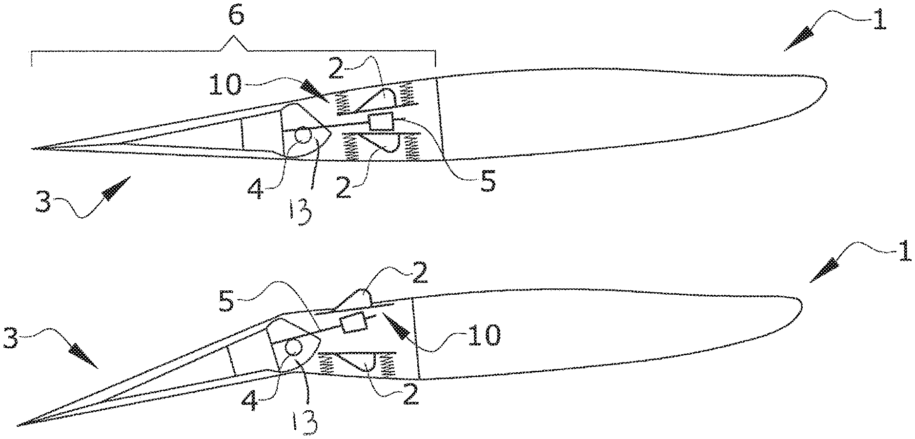
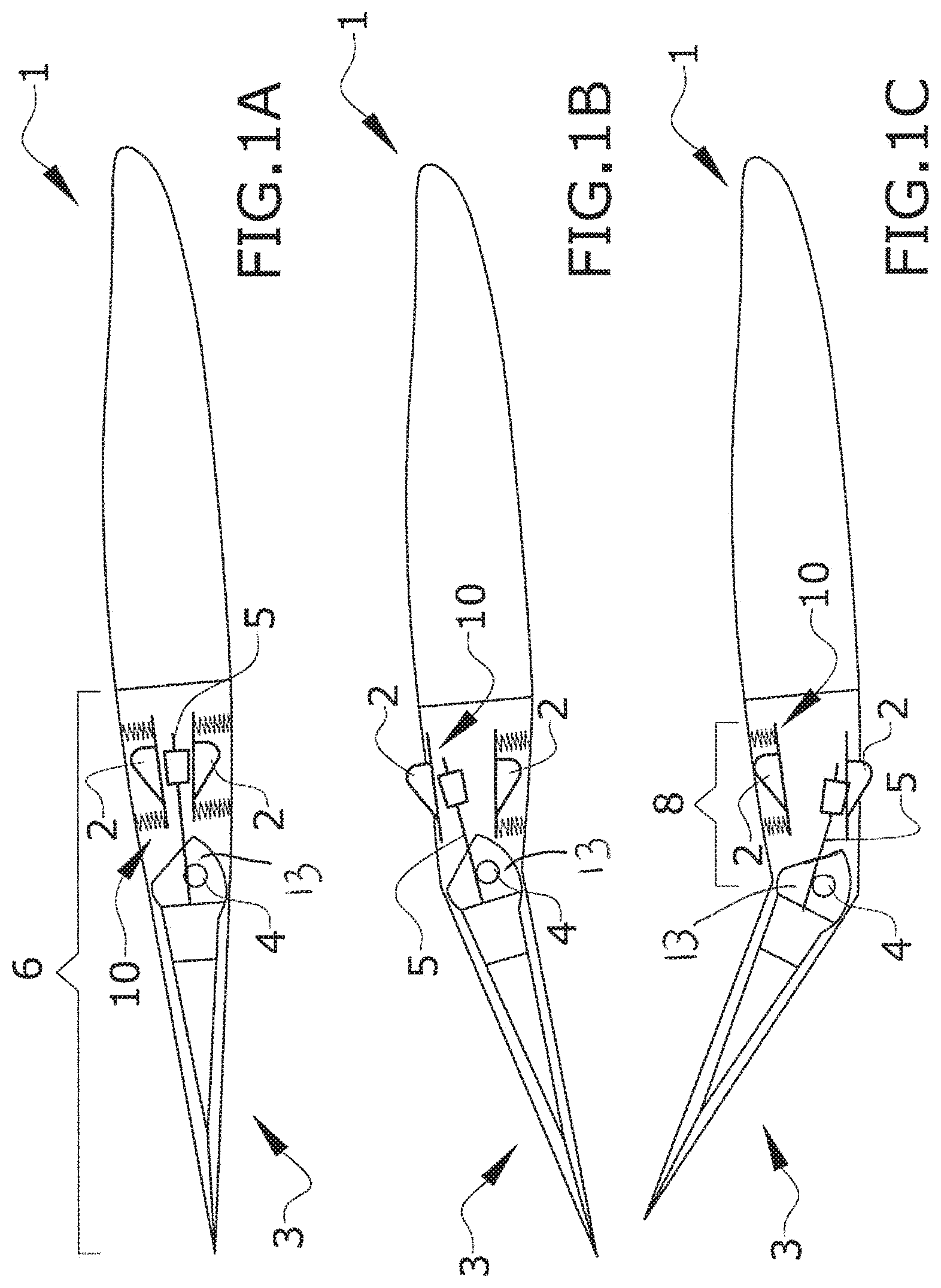
FIGS. 1A, 1B and 1C show a cross section of a first embodiment of a lifting surface having a trailing edge and an elevator in three different positions.
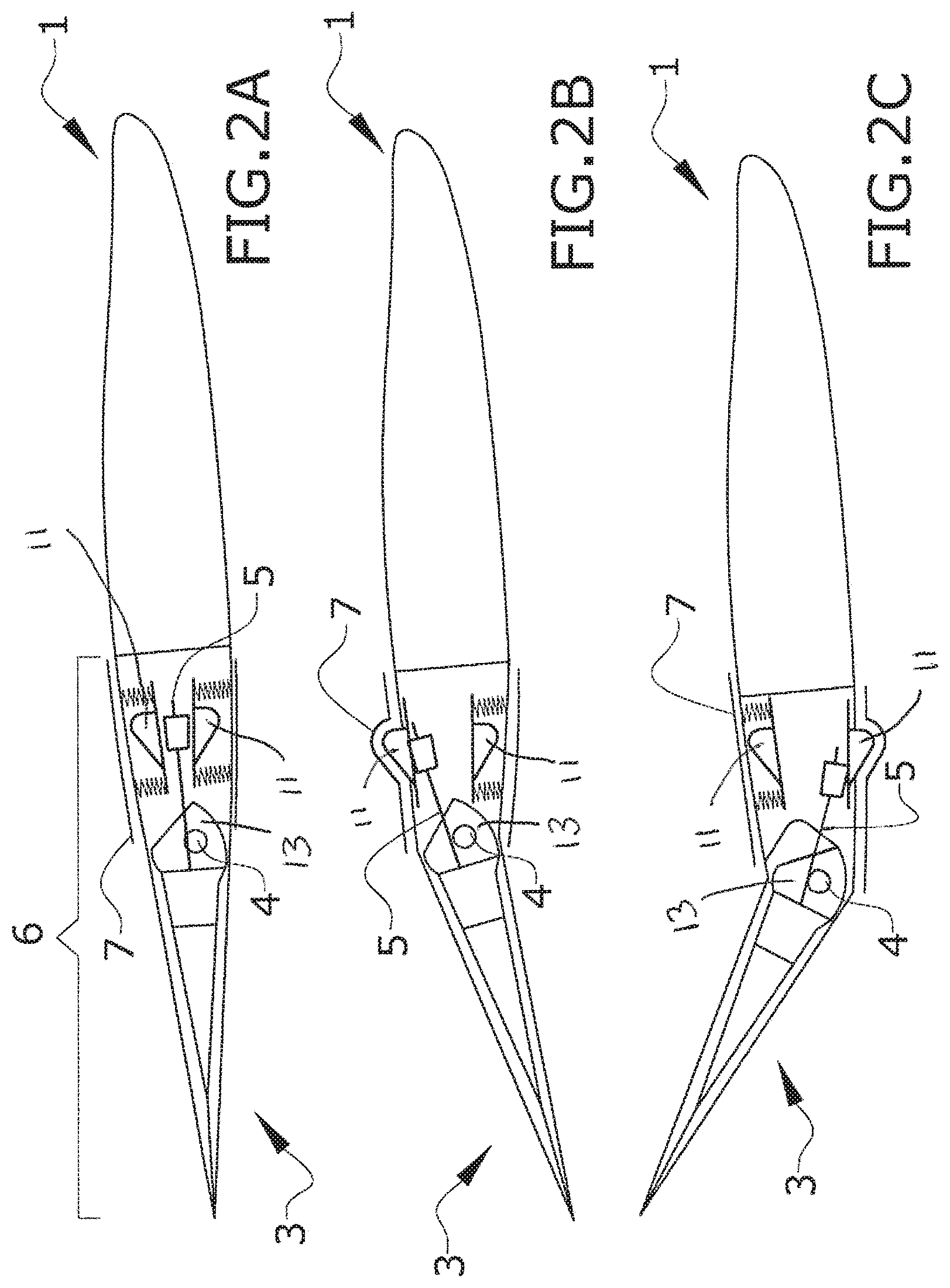
FIGS. 2A, 2B and 2C show a cross section of a second embodiment of a lifting surface having a trailing edge and an elevator in three different positions.
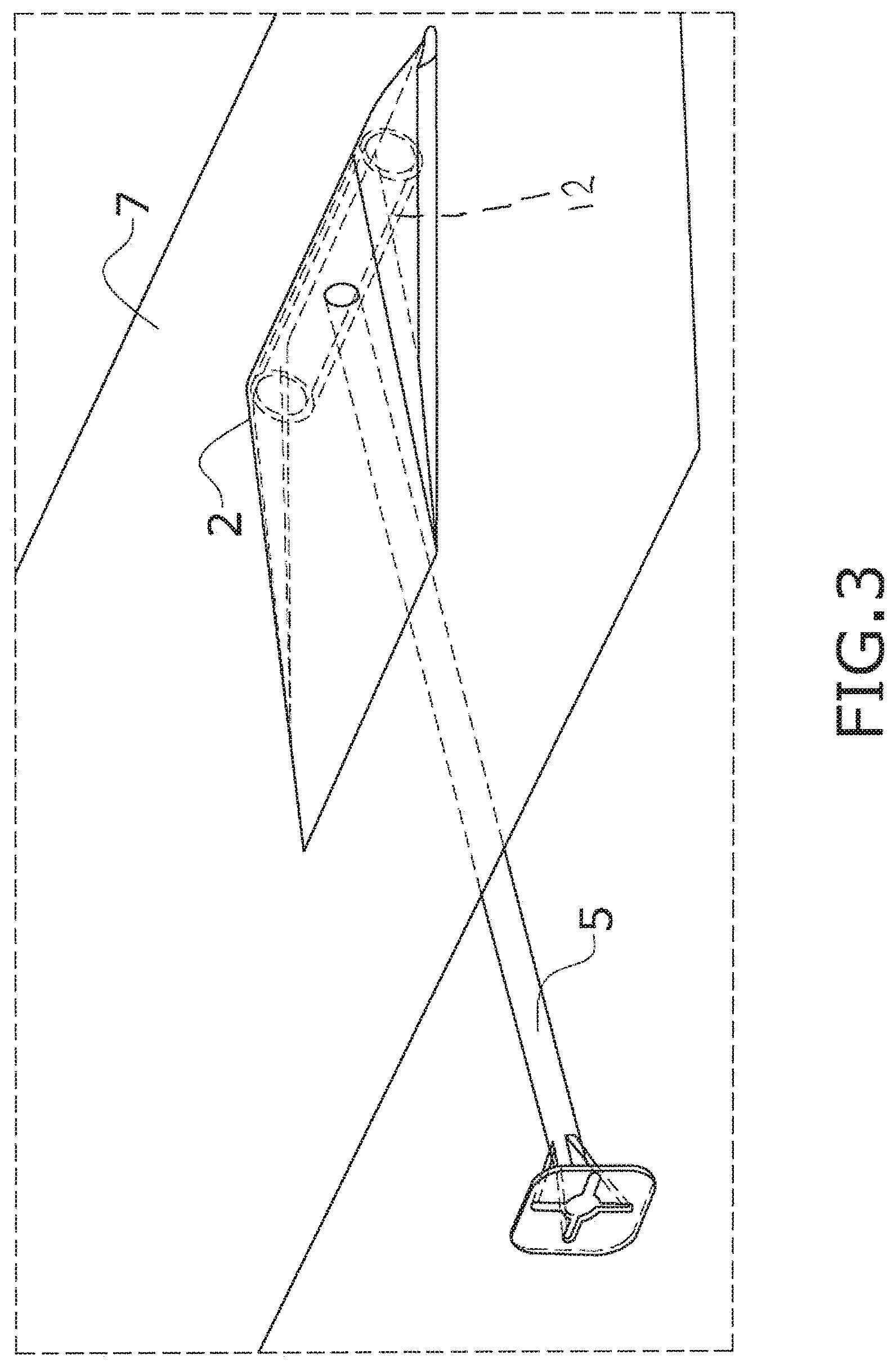
FIG. 3 shows a schematic perspective view of a third embodiment of the discontinuity being pressed by the bar.
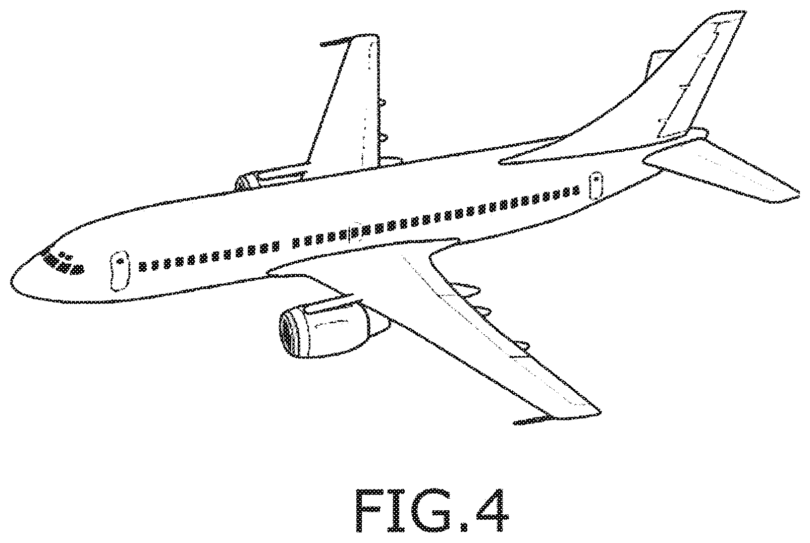
FIG. 4 shows a schematic perspective view of an aircraft having a lifting surface according to the invention.
DETAILED DESCRIPTION OF THE PREFERRED EMBODIMENTS
FIGS. 1 and 2 show two embodiments of the invention showing in FIGS. 1A, 1B and 1C a first embodiment in which some openings (10) are located on the trailing edge (6) in order to allow the movable discontinuities (2) to come out when the elevator (3) rotates around a hinge line (4). More specifically, the movable discontinuity (2) is located in the trailing edge panels (8) of the lifting surface (1). This first embodiment has the disadvantage of impacting aerodynamics due to the openings (10) at the trailing edge (6).
FIGS. 2A, 2B and 2C show a second embodiment in which a flexible skin (7) is included at the vortex generators affected area in order to mitigate the aerodynamic impact due to the openings (10).
Upper and lower trailing edge panels (8) are manufactured with flexible skins (7) of aramid, nylon, polyester or other fabrics, stiff enough to avoid unallowable deformations and flexible enough to change their position according with the inner kinematic of the vortex generators elements.
In this embodiment, the movable discontinuity (2) therefore comprises two different elements, an intermediate element (11) that is pushed by the bar (5) and the flexible skin (7) that is, in turn, pushed by the intermediate element (11).
Preferably, the element to which the bar (5) is attached is the front spar (13) of the elevator (3). The front spar (13) is sufficiently rigid and does not move relative to the other elements of the elevator (3), so that the movement of the bar (5) is made jointly with the movement of the elevator (3).
FIG. 3 shows an additional embodiment comprising a flexible skin (7) but in this embodiment the end of the bar (5) is adapted to produce the deformation in the flexible skin (7) by having a corresponding shape. In the shown embodiment, the end of the bar (5) comprises a cylindrical element (12) having its longitudinal axis perpendicular to the axis of the bar (5).
Although all the three shown embodiments show that the bar (5) pushes the movable discontinuity (2) such that it comes out from the surface of the lifting surface (1) forming a protuberance another possibility exists wherein the bar (5) pull the movable discontinuity (2) such that it comes in from the surface of the lifting surface (1) forming a recess in the surface.
The movable discontinuity (2) would preferably be located in the surface of the lifting surface (1) more appropriate for the stability and control of the aircraft, for instance, in the face having a negative pressure gradient or what is the same, wherein the suction pressures are produced instead than in the positive pressures face of the lifting surface (1).
Note that vortex generators shapes can be different (rectangular, triangular, ogive, parabolic, gothic, inverse triangular, . . . ).
While at least one exemplary embodiment of the present invention(s) is disclosed herein, it should be understood that modifications, substitutions and alternatives may be apparent to one of ordinary skill in the art and can be made without departing from the scope of this disclosure. This disclosure is intended to cover any adaptations or variations of the exemplary embodiment(s). In addition, in this disclosure, the terms "comprise" or "comprising" do not exclude other elements or steps, the terms "a" or "one" do not exclude a plural number, and the term "or" means either or both. Furthermore, characteristics or steps which have been described may also be used in combination with other characteristics or steps and in any order unless the disclosure or context suggests otherwise. This disclosure hereby incorporates by reference the complete disclosure of any patent or application from which it claims benefit or priority.
* * * * *
D00000
D00001
D00002
D00003
D00004
XML
uspto.report is an independent third-party trademark research tool that is not affiliated, endorsed, or sponsored by the United States Patent and Trademark Office (USPTO) or any other governmental organization. The information provided by uspto.report is based on publicly available data at the time of writing and is intended for informational purposes only.
While we strive to provide accurate and up-to-date information, we do not guarantee the accuracy, completeness, reliability, or suitability of the information displayed on this site. The use of this site is at your own risk. Any reliance you place on such information is therefore strictly at your own risk.
All official trademark data, including owner information, should be verified by visiting the official USPTO website at www.uspto.gov. This site is not intended to replace professional legal advice and should not be used as a substitute for consulting with a legal professional who is knowledgeable about trademark law.