Lead assemblies with arrangements to confirm alignment between terminals and contacts
Nageri , et al. February 2, 2
U.S. patent number 10,905,871 [Application Number 15/878,085] was granted by the patent office on 2021-02-02 for lead assemblies with arrangements to confirm alignment between terminals and contacts. This patent grant is currently assigned to BOSTON SCIENTIFIC NEUROMODULATION CORPORATION. The grantee listed for this patent is Boston Scientific Neuromodulation Corporation. Invention is credited to Ranjan Krishna Mukhari Nageri, Peter J. Yoo.


| United States Patent | 10,905,871 |
| Nageri , et al. | February 2, 2021 |
Lead assemblies with arrangements to confirm alignment between terminals and contacts
Abstract
A lead assembly includes a lead or lead extension having terminals and a mechanical stop fixed to the lead or lead extension and located distally to the plurality of terminals. The lead assembly also includes a connector having a connector housing, a connector block disposed within the connector housing, a port defined at the distal surface of the connector housing, a lumen extending from the port for receiving a portion the lead or lead extension, and contacts disposed within the connector housing. The outer diameter of the mechanical stop is larger than the lumen diameter within the connector block to halt further insertion of the lead or lead extension into the connector housing. Additionally or alternatively, a visually distinctive marking can be applied to the lead or lead extension to indicate alignment between the terminals of the lead and the contacts of the connector.
| Inventors: | Nageri; Ranjan Krishna Mukhari (Valencia, CA), Yoo; Peter J. (Burbank, CA) | ||||||||||
|---|---|---|---|---|---|---|---|---|---|---|---|
| Applicant: |
|
||||||||||
| Assignee: | BOSTON SCIENTIFIC NEUROMODULATION
CORPORATION (Valencia, CA) |
||||||||||
| Family ID: | 1000005333853 | ||||||||||
| Appl. No.: | 15/878,085 | ||||||||||
| Filed: | January 23, 2018 |
Prior Publication Data
| Document Identifier | Publication Date | |
|---|---|---|
| US 20180214687 A1 | Aug 2, 2018 | |
Related U.S. Patent Documents
| Application Number | Filing Date | Patent Number | Issue Date | ||
|---|---|---|---|---|---|
| 62451513 | Jan 27, 2017 | ||||
| Current U.S. Class: | 1/1 |
| Current CPC Class: | A61N 1/0553 (20130101); H01R 13/641 (20130101); H01R 24/58 (20130101); A61N 1/3752 (20130101); H01R 2201/12 (20130101); H01R 2107/00 (20130101) |
| Current International Class: | A61N 1/05 (20060101); H01R 13/641 (20060101); H01R 24/58 (20110101); A61N 1/375 (20060101) |
References Cited [Referenced By]
U.S. Patent Documents
| 3222471 | December 1965 | Steinkamp |
| 3601747 | August 1971 | Prat et al. |
| 3718142 | February 1973 | Mulier |
| 3757789 | September 1973 | Shanker |
| 3771106 | November 1973 | Matsumoto et al. |
| 3908668 | September 1975 | Bolduc |
| 3951154 | April 1976 | Hartlaub |
| 3990727 | November 1976 | Gallagher |
| 4003616 | January 1977 | Springer |
| 4112953 | September 1978 | Shanker et al. |
| 4142532 | March 1979 | Ware |
| 4180078 | December 1979 | Anderson |
| 4245642 | January 1981 | Skubitz et al. |
| 4259962 | April 1981 | Peers-Trevarton |
| 4310001 | January 1982 | Comben |
| 4364625 | December 1982 | Baker et al. |
| 4367907 | January 1983 | Buck |
| 4411276 | October 1983 | Dickhudt et al. |
| 4411277 | October 1983 | Dickhudt |
| 4461194 | July 1984 | Moore |
| 4466441 | August 1984 | Skubitz et al. |
| 4516820 | May 1985 | Kuzma |
| RE31990 | September 1985 | Sluetz et al. |
| 4540236 | September 1985 | Peers-Trevarton |
| 4602624 | July 1986 | Naples et al. |
| 4603696 | August 1986 | Cross, Jr. et al. |
| 4614395 | September 1986 | Peers-Trevarton |
| 4630611 | December 1986 | King |
| 4695116 | September 1987 | Bailey et al. |
| 4695117 | September 1987 | Kysiak |
| 4712557 | December 1987 | Harris |
| 4715380 | December 1987 | Harris |
| 4744370 | May 1988 | Harris |
| 4784141 | November 1988 | Peers-Trevarton |
| 4832032 | May 1989 | Schneider |
| 4840580 | June 1989 | Saell et al. |
| 4850359 | July 1989 | Putz |
| 4860750 | August 1989 | Frey et al. |
| 4867708 | September 1989 | Iizuka |
| 4869255 | September 1989 | Putz |
| 4898173 | February 1990 | Daglow et al. |
| 4899753 | February 1990 | Inoue et al. |
| 4951687 | August 1990 | Ufford et al. |
| 4995389 | February 1991 | Harris |
| 5000177 | March 1991 | Hoffmann et al. |
| 5000194 | March 1991 | van den Honert et al. |
| 5007435 | April 1991 | Doan et al. |
| 5007864 | April 1991 | Stutz, Jr. |
| 5070605 | December 1991 | Daglow et al. |
| 5082453 | January 1992 | Stutz, Jr. |
| 5086773 | February 1992 | Ware |
| 5135001 | August 1992 | Sinofsky et al. |
| 5193539 | March 1993 | Schulman et al. |
| 5193540 | March 1993 | Schulman et al. |
| 5201865 | April 1993 | Kuehn |
| 5241957 | September 1993 | Camps et al. |
| 5252090 | October 1993 | Giurtino et al. |
| 5261395 | November 1993 | Oleen et al. |
| 5312439 | May 1994 | Loeb |
| 5324312 | June 1994 | Stokes et al. |
| 5330521 | July 1994 | Cohen |
| 5336246 | August 1994 | Dantanarayana |
| 5348481 | September 1994 | Ortiz |
| 5354326 | October 1994 | Comben et al. |
| 5358514 | October 1994 | Schulman et al. |
| 5368496 | November 1994 | Ranalletta et al. |
| 5374279 | December 1994 | Duffin, Jr. et al. |
| 5374285 | December 1994 | Vaiani et al. |
| 5383913 | January 1995 | Schiff |
| 5413595 | May 1995 | Stutz, Jr. |
| 5433734 | July 1995 | Stokes et al. |
| 5435731 | July 1995 | Kang |
| 5458629 | October 1995 | Baudino et al. |
| 5486202 | January 1996 | Bradshaw |
| 5489225 | February 1996 | Julian |
| 5509928 | April 1996 | Acken |
| 5522874 | June 1996 | Gates |
| 5534019 | July 1996 | Paspa |
| 5545188 | August 1996 | Bradshaw et al. |
| 5545189 | August 1996 | Fayram |
| 5560358 | October 1996 | Arnold et al. |
| 5582180 | December 1996 | Manset et al. |
| 5679026 | October 1997 | Fain et al. |
| 5683433 | November 1997 | Carson |
| 5711316 | January 1998 | Elsberry et al. |
| 5713922 | February 1998 | King |
| 5720631 | February 1998 | Carson et al. |
| 5730628 | March 1998 | Hawkins |
| 5755743 | May 1998 | Volz et al. |
| 5766042 | June 1998 | Ries et al. |
| 5782892 | July 1998 | Castle et al. |
| 5796044 | August 1998 | Cobian et al. |
| 5800350 | September 1998 | Coppleson et al. |
| 5800495 | September 1998 | Machek et al. |
| 5807144 | September 1998 | Sivard |
| 5837006 | November 1998 | Ocel et al. |
| 5843141 | December 1998 | Bischoff et al. |
| 5843148 | December 1998 | Gijsbers et al. |
| 5906634 | May 1999 | Flynn et al. |
| 5931861 | August 1999 | Werner et al. |
| 5938688 | August 1999 | Schiff |
| 5951595 | September 1999 | Moberg et al. |
| 5968082 | October 1999 | Heil |
| 5987361 | November 1999 | Mortimer |
| 5989077 | November 1999 | Mast et al. |
| 6006135 | December 1999 | Kest et al. |
| 6018684 | January 2000 | Bartig et al. |
| 6038479 | March 2000 | Werner et al. |
| 6038481 | March 2000 | Werner et al. |
| 6042432 | March 2000 | Hashazawa et al. |
| 6051017 | April 2000 | Loeb et al. |
| 6080188 | June 2000 | Rowley et al. |
| 6112120 | August 2000 | Correas |
| 6112121 | August 2000 | Paul et al. |
| 6125302 | September 2000 | Kuzma |
| 6134478 | October 2000 | Spehr |
| 6154678 | November 2000 | Laura |
| 6161047 | December 2000 | King et al. |
| 6162101 | December 2000 | Fischer et al. |
| 6164284 | December 2000 | Schulman et al. |
| 6167311 | December 2000 | Rezai |
| 6167314 | December 2000 | Fischer, Sr. et al. |
| 6175710 | January 2001 | Kamaji et al. |
| 6181969 | January 2001 | Gord |
| 6185452 | February 2001 | Schulman et al. |
| 6192278 | February 2001 | Werner et al. |
| 6198969 | March 2001 | Kuzma |
| 6208894 | March 2001 | Schulman et al. |
| 6224450 | May 2001 | Norton |
| 6271094 | August 2001 | Boyd et al. |
| 6295944 | October 2001 | Lovett |
| 6319021 | November 2001 | Billman |
| 6321126 | November 2001 | Kuzma |
| 6322559 | November 2001 | Daulton et al. |
| 6343233 | January 2002 | Werner et al. |
| 6364278 | April 2002 | Lin et al. |
| 6370434 | April 2002 | Zhang et al. |
| 6391985 | May 2002 | Goode et al. |
| 6397108 | May 2002 | Camps et al. |
| 6415168 | July 2002 | Putz |
| 6428336 | August 2002 | Akerfeldt |
| 6428368 | August 2002 | Hawkins et al. |
| 6430442 | August 2002 | Peters et al. |
| 6466824 | October 2002 | Struble |
| 6473654 | October 2002 | Chinn |
| 6498952 | December 2002 | Imani et al. |
| 6510347 | January 2003 | Borkan |
| 6516227 | February 2003 | Meadows et al. |
| 6556873 | April 2003 | Smits |
| 6564078 | May 2003 | Marino et al. |
| 6604283 | August 2003 | Kuzma |
| 6605094 | August 2003 | Mann et al. |
| 6609029 | August 2003 | Mann et al. |
| 6609032 | August 2003 | Woods et al. |
| 6654641 | November 2003 | Froberg |
| 6662035 | December 2003 | Sochor |
| 6663570 | December 2003 | Mott |
| 6671534 | December 2003 | Putz |
| 6671553 | December 2003 | Helland et al. |
| 6678564 | January 2004 | Ketterl et al. |
| 6725096 | April 2004 | Chinn et al. |
| 6741892 | May 2004 | Meadows et al. |
| 6757039 | June 2004 | Ma |
| 6757970 | July 2004 | Kuzma et al. |
| 6799991 | October 2004 | Williams et al. |
| 6805675 | October 2004 | Gardeski et al. |
| 6854994 | February 2005 | Stein et al. |
| 6878013 | April 2005 | Behan |
| 6895276 | May 2005 | Kast et al. |
| 6913478 | July 2005 | Lamrey |
| 6921295 | July 2005 | Sommer et al. |
| 6968235 | November 2005 | Belden et al. |
| 6980863 | December 2005 | van Venrooj et al. |
| 7027852 | April 2006 | Helland |
| 7047084 | May 2006 | Erickson et al. |
| 7058452 | June 2006 | Dahberg |
| 7069081 | June 2006 | Biggs et al. |
| 7083474 | August 2006 | Fleck et al. |
| 7108549 | September 2006 | Lyu et al. |
| 7110827 | September 2006 | Sage et al. |
| 7128600 | October 2006 | Osypka |
| 7155283 | December 2006 | Ries et al. |
| 7164951 | January 2007 | Ries et al. |
| 7168165 | January 2007 | Calzada et al. |
| 7191009 | March 2007 | Laske et al. |
| 7195523 | March 2007 | Naviaux |
| 7203548 | April 2007 | Whitehurst et al. |
| 7225034 | May 2007 | Ries et al. |
| 7231253 | June 2007 | Tidemand et al. |
| 7241180 | July 2007 | Rentas |
| 7242987 | July 2007 | Holleman et al. |
| 7244150 | July 2007 | Brase et al. |
| 7270568 | September 2007 | Osypka |
| 7283878 | October 2007 | Brostrom et al. |
| 7286882 | October 2007 | Cole |
| 7287995 | October 2007 | Stein et al. |
| 7292890 | November 2007 | Whitehurst et al. |
| 7396335 | July 2008 | Gardeski et al. |
| 7402083 | July 2008 | Kast et al. |
| 7422487 | September 2008 | Osypka |
| 7430958 | October 2008 | Wong |
| 7437193 | October 2008 | Parramon et al. |
| 7450997 | November 2008 | Pianca et al. |
| 7489971 | February 2009 | Franz |
| 7512446 | March 2009 | Honeck |
| 7516447 | April 2009 | Marvin et al. |
| 7526339 | April 2009 | Lahti et al. |
| 7539542 | May 2009 | Malinowski |
| 7548788 | June 2009 | Chinn et al. |
| 7554493 | June 2009 | Rahman |
| 7583999 | September 2009 | Bedenbaugh |
| 7585190 | September 2009 | Osypka |
| 7590451 | September 2009 | Tronnes et al. |
| 7650184 | January 2010 | Walter |
| 7668601 | February 2010 | Hegland et al. |
| 7672734 | March 2010 | Anderson et al. |
| 7736191 | June 2010 | Sochor |
| 7758384 | July 2010 | Alexander et al. |
| 7761165 | July 2010 | He et al. |
| 7761985 | July 2010 | Hegland et al. |
| 7783359 | August 2010 | Meadows |
| 7792590 | September 2010 | Pianca et al. |
| 7798864 | September 2010 | Barker et al. |
| 7803021 | September 2010 | Brase |
| 7809446 | October 2010 | Meadows |
| 7822477 | October 2010 | Rey et al. |
| 7822482 | October 2010 | Gerber |
| 7840188 | November 2010 | Kurokawa |
| 7848802 | December 2010 | Goetz |
| 7856707 | December 2010 | Cole |
| 7860570 | December 2010 | Whitehurst et al. |
| 7949395 | May 2011 | Kuzma |
| 7974705 | July 2011 | Zdeblick et al. |
| 7974706 | July 2011 | Moffitt et al. |
| 7979140 | July 2011 | Schulman |
| 8000808 | August 2011 | Hegland et al. |
| 8019440 | September 2011 | Kokones et al. |
| 8036755 | October 2011 | Franz |
| 8041309 | October 2011 | Kurokawa |
| 8046073 | October 2011 | Pianca |
| 8046074 | October 2011 | Barker |
| 8078280 | December 2011 | Sage |
| 8099177 | January 2012 | Dahlberg |
| 8100726 | January 2012 | Harlan et al. |
| 8140163 | March 2012 | Daglow et al. |
| 8167660 | May 2012 | Dilmaghanian et al. |
| 8175710 | May 2012 | He |
| 8190259 | May 2012 | Smith et al. |
| 8206180 | June 2012 | Kast et al. |
| 8224450 | July 2012 | Brase |
| 8225504 | July 2012 | Dye et al. |
| 8239042 | August 2012 | Chinn et al. |
| 8271094 | September 2012 | Moffitt et al. |
| 8295944 | October 2012 | Howard et al. |
| 8301255 | October 2012 | Barker |
| 8321025 | November 2012 | Bedenbaugh |
| 8342887 | January 2013 | Gleason et al. |
| 8359107 | January 2013 | Pianca et al. |
| 8364278 | January 2013 | Pianca et al. |
| 8391985 | March 2013 | McDonald |
| 8412330 | April 2013 | Kast et al. |
| 8527054 | September 2013 | North |
| 8583237 | November 2013 | Bedenbaugh |
| 8600507 | December 2013 | Brase et al. |
| 8682439 | March 2014 | DeRohan et al. |
| 8688235 | April 2014 | Pianca |
| 8784143 | July 2014 | Edgell et al. |
| 8831742 | September 2014 | Pianca et al. |
| 8849396 | September 2014 | DeRohan et al. |
| 8849415 | September 2014 | Bedenbaugh |
| 8897876 | November 2014 | Sundaramurthy et al. |
| 8897891 | November 2014 | Romero |
| 8968331 | March 2015 | Sochor |
| 9101775 | August 2015 | Barker |
| 9149630 | October 2015 | Howard et al. |
| 9162048 | October 2015 | Romero et al. |
| 9234591 | January 2016 | Dilmaghanian et al. |
| 9270070 | February 2016 | Pianca |
| 9289596 | March 2016 | Leven |
| 9352147 | May 2016 | Nguyen-stella et al. |
| 9381348 | July 2016 | Romero et al. |
| 9403022 | August 2016 | Ries et al. |
| 9409032 | August 2016 | Brase et al. |
| 9440066 | September 2016 | Black |
| 9498618 | November 2016 | Stetson et al. |
| 9498620 | November 2016 | Romero et al. |
| 9504839 | November 2016 | Leven |
| 9604068 | March 2017 | Malinowski |
| 9656093 | May 2017 | Villarta et al. |
| 9770598 | September 2017 | Malinowski et al. |
| 9855413 | January 2018 | Vadlamudi et al. |
| 2001/0023368 | September 2001 | Black et al. |
| 2002/0143376 | October 2002 | Chinn et al. |
| 2002/0156513 | October 2002 | Borkan |
| 2002/0183817 | December 2002 | Van Venrooij et al. |
| 2003/0163171 | August 2003 | Kast et al. |
| 2004/0064164 | April 2004 | Ries et al. |
| 2004/0230268 | November 2004 | Huff et al. |
| 2004/0260373 | December 2004 | Ries et al. |
| 2005/0015130 | January 2005 | Gill |
| 2005/0027326 | February 2005 | Ries et al. |
| 2005/0027327 | February 2005 | Ries et al. |
| 2005/0038489 | February 2005 | Grill |
| 2005/0043770 | February 2005 | Hine et al. |
| 2005/0043771 | February 2005 | Sommer |
| 2005/0137665 | June 2005 | Cole |
| 2005/0171587 | August 2005 | Daglow et al. |
| 2005/0186829 | August 2005 | Balsells |
| 2005/0272280 | December 2005 | Osypka |
| 2006/0015163 | January 2006 | Brown |
| 2006/0025841 | February 2006 | McIntyre |
| 2006/0030918 | February 2006 | Chinn |
| 2006/0089681 | April 2006 | Tumlinson |
| 2006/0167522 | July 2006 | Malinowski |
| 2006/0224208 | October 2006 | Naviaux |
| 2006/0247697 | November 2006 | Sharma et al. |
| 2006/0247749 | November 2006 | Colvin |
| 2006/0259106 | November 2006 | Arnholt et al. |
| 2007/0042648 | February 2007 | Balsells |
| 2007/0142889 | June 2007 | Whitehurst et al. |
| 2007/0150036 | June 2007 | Anderson |
| 2007/0161294 | July 2007 | Brase et al. |
| 2007/0168007 | July 2007 | Kuzma et al. |
| 2007/0203546 | August 2007 | Stone et al. |
| 2007/0219551 | September 2007 | Honour et al. |
| 2008/0077186 | March 2008 | Thompson et al. |
| 2008/0103580 | May 2008 | Gerber |
| 2008/0114230 | May 2008 | Addis |
| 2008/0139031 | June 2008 | Ries et al. |
| 2008/0177167 | July 2008 | Janzig et al. |
| 2008/0208277 | August 2008 | Janzig et al. |
| 2008/0208278 | August 2008 | Janzig et al. |
| 2008/0208279 | August 2008 | Janzig et al. |
| 2008/0215125 | September 2008 | Farah et al. |
| 2008/0255647 | October 2008 | Jensen et al. |
| 2008/0274651 | November 2008 | Boyd et al. |
| 2009/0054941 | February 2009 | Eggen et al. |
| 2009/0187222 | July 2009 | Barker |
| 2009/0204192 | August 2009 | Carlton et al. |
| 2009/0264943 | October 2009 | Barker |
| 2009/0276021 | November 2009 | Meadows et al. |
| 2009/0287191 | November 2009 | Ferren et al. |
| 2010/0029127 | February 2010 | Sjostedt |
| 2010/0030298 | February 2010 | Martens et al. |
| 2010/0036468 | February 2010 | Decre et al. |
| 2010/0057176 | March 2010 | Barker |
| 2010/0070012 | March 2010 | Chinn et al. |
| 2010/0076535 | March 2010 | Pianca et al. |
| 2010/0077606 | April 2010 | Black et al. |
| 2010/0082076 | April 2010 | Lee et al. |
| 2010/0094387 | April 2010 | Pianca et al. |
| 2010/0100152 | April 2010 | Martens et al. |
| 2010/0268298 | October 2010 | Moffitt et al. |
| 2010/0269338 | October 2010 | Dye |
| 2010/0269339 | October 2010 | Dye et al. |
| 2010/0287770 | November 2010 | Dadd et al. |
| 2011/0004267 | January 2011 | Meadows |
| 2011/0005069 | January 2011 | Pianca |
| 2011/0022100 | January 2011 | Brase et al. |
| 2011/0047795 | March 2011 | Turner et al. |
| 2011/0056076 | March 2011 | Hegland et al. |
| 2011/0077699 | March 2011 | Swanson et al. |
| 2011/0078900 | April 2011 | Pianca et al. |
| 2011/0130803 | June 2011 | McDonald |
| 2011/0130816 | June 2011 | Howard et al. |
| 2011/0130817 | June 2011 | Chen |
| 2011/0130818 | June 2011 | Chen |
| 2011/0131808 | June 2011 | Gill |
| 2011/0184480 | July 2011 | Kast et al. |
| 2011/0238129 | September 2011 | Moffitt et al. |
| 2011/0245903 | October 2011 | Schulte et al. |
| 2011/0270330 | November 2011 | Janzig et al. |
| 2011/0301665 | December 2011 | Mercanzini et al. |
| 2011/0313500 | December 2011 | Barker et al. |
| 2012/0016378 | January 2012 | Pianca et al. |
| 2012/0046710 | February 2012 | DiGiore et al. |
| 2012/0053646 | March 2012 | Brase et al. |
| 2012/0071937 | March 2012 | Sundaramurthy et al. |
| 2012/0071949 | March 2012 | Pianca et al. |
| 2012/0165911 | June 2012 | Pianca |
| 2012/0185019 | July 2012 | Schramm et al. |
| 2012/0197375 | August 2012 | Pianca et al. |
| 2012/0203302 | August 2012 | Moffitt et al. |
| 2012/0203316 | August 2012 | Moffitt et al. |
| 2012/0203320 | August 2012 | DiGiore et al. |
| 2012/0203321 | August 2012 | Moffitt et al. |
| 2012/0232603 | September 2012 | Sage |
| 2012/0253443 | October 2012 | Dilmaghanian et al. |
| 2012/0259386 | October 2012 | DeRohan et al. |
| 2012/0316615 | December 2012 | DiGiore et al. |
| 2013/0053864 | February 2013 | Geroy et al. |
| 2013/0098678 | April 2013 | Barker |
| 2013/0105071 | May 2013 | DiGiore et al. |
| 2013/0109254 | May 2013 | Klardie et al. |
| 2013/0116754 | May 2013 | Sharma et al. |
| 2013/0149031 | June 2013 | Changsrivong et al. |
| 2013/0197424 | August 2013 | Bedenbaugh |
| 2013/0197602 | August 2013 | Pianca et al. |
| 2013/0197603 | August 2013 | Eiger |
| 2013/0218154 | August 2013 | Carbunaru |
| 2013/0261684 | October 2013 | Howard |
| 2013/0288501 | October 2013 | Russell et al. |
| 2013/0304140 | November 2013 | Derohan et al. |
| 2013/0317587 | November 2013 | Barker |
| 2013/0325091 | December 2013 | Pianca et al. |
| 2014/0039587 | February 2014 | Romero |
| 2014/0088666 | March 2014 | Goetz et al. |
| 2014/0142671 | May 2014 | Moffitt et al. |
| 2014/0148885 | May 2014 | DeRohan et al. |
| 2014/0180375 | June 2014 | Pianca et al. |
| 2014/0353001 | December 2014 | Romero et al. |
| 2014/0358207 | December 2014 | Romero |
| 2014/0358208 | December 2014 | Howard et al. |
| 2014/0358209 | December 2014 | Romero et al. |
| 2014/0358210 | December 2014 | Howard et al. |
| 2015/0018915 | January 2015 | Leven |
| 2015/0021817 | January 2015 | Romero et al. |
| 2015/0025609 | January 2015 | Govea |
| 2015/0045864 | February 2015 | Howard |
| 2015/0066120 | March 2015 | Govea |
| 2015/0119965 | April 2015 | Govea |
| 2015/0151113 | June 2015 | Govea et al. |
| 2015/0209575 | July 2015 | Black |
| 2015/0360023 | December 2015 | Howard et al. |
| 2015/0374978 | December 2015 | Howard et al. |
| 2016/0059019 | March 2016 | Malinowski et al. |
| 2016/0129242 | May 2016 | Malinowski |
| 2016/0129265 | May 2016 | Malinowski |
| 2016/0158558 | June 2016 | Shanahan et al. |
| 2016/0206891 | July 2016 | Howard et al. |
| 2016/0228692 | August 2016 | Steinke et al. |
| 2016/0296745 | October 2016 | Govea |
| 2016/0375238 | December 2016 | Leven et al. |
| 2017/0072187 | March 2017 | Howard et al. |
| 2017/0143978 | May 2017 | Barker |
| 2017/0203104 | July 2017 | Nageri et al. |
| 2017/0361108 | December 2017 | Leven |
| 2018/0008832 | January 2018 | Leven |
| 2018/0028820 | February 2018 | Nageri |
| 2018/0093098 | April 2018 | Nageri et al. |
| 2018/0214687 | August 2018 | Nageri et al. |
| 2018/0243570 | August 2018 | Malinowski et al. |
| 2018/0289968 | October 2018 | Lopez |
| 2018/0369596 | December 2018 | Funderburk |
| 2019/0030345 | January 2019 | Funderburk |
| 2019/0083793 | March 2019 | Nageri |
| 2019/0083794 | March 2019 | Nageri |
| 2019/0103696 | April 2019 | Conger |
| 0580928 | Feb 1994 | EP | |||
| 0650694 | Jul 1998 | EP | |||
| 0832667 | Feb 2004 | EP | |||
| 1181947 | Jan 2006 | EP | |||
| 1625875 | Feb 2006 | EP | |||
| 2092952 | Aug 2009 | EP | |||
| 1997032628 | Sep 1997 | WO | |||
| 1999055411 | Feb 2000 | WO | |||
| 2000038574 | Jul 2000 | WO | |||
| 2001058520 | Aug 2001 | WO | |||
| 2002068042 | Sep 2002 | WO | |||
| 2004045707 | Jun 2004 | WO | |||
| 2008018067 | Feb 2008 | WO | |||
| 2008053789 | May 2008 | WO | |||
| 2008100841 | Aug 2008 | WO | |||
| 2009025816 | Feb 2009 | WO | |||
| 2009102536 | Aug 2009 | WO | |||
| 2009/148939 | Dec 2009 | WO | |||
| 2013162775 | Oct 2013 | WO | |||
| 2014018092 | Jan 2014 | WO | |||
Attorney, Agent or Firm: Branch Partners PLLC Black; Bruce E.
Parent Case Text
CROSS-REFERENCE TO RELATED APPLICATIONS
This application claims the benefit under 35 U.S.C. .sctn. 119(e) of U.S. Provisional Patent Application Ser. No. 62/451,513, filed Jan. 27, 2017, which is incorporated herein by reference.
Claims
What is claimed as new and desired to be protected is:
1. A lead assembly comprising: a lead or lead extension comprising a plurality of terminals and a visually distinctive marking applied to the lead or lead extension, the marking located distally from the plurality of terminals; and a connector comprising a connector housing having a distal surface and a longitudinal axis, a connector block disposed within the connector housing, a port defined at the distal surface of the connector housing, a lumen extending from the port along the longitudinal axis of the connector housing and through the connector block, the lumen is configured for receiving a portion the lead or lead extension and has a lumen diameter within the connector block, and a plurality of contacts disposed within the connector housing proximal to the connector block, wherein the contacts are configured to electrically couple to the terminals when the portion of the lead or lead extension is received within the lumen of the connector, wherein the marking is configured and arranged such that, upon insertion of the lead or lead extension into the connector housing, longitudinal alignment of the terminals of the lead or lead extension with the contacts disposed in the connector housing is indicated by the marking being entirely masked by the connector housing.
2. The lead assembly of claim 1, wherein the lead or lead extension further comprises a retention sleeve disposed distal to the plurality of terminals.
3. The lead assembly of claim 2, wherein the marking is applied to the retention sleeve.
4. The lead assembly of claim 1, wherein the marking has a color that visually contrasts with a color of the lead or lead extension and further visually contrasts with a color of the connector housing.
5. The lead assembly of claim 1, further comprising a fastener insertable into the connector block to securely fix the lead or lead extension to the connector block.
6. An electrical stimulating system comprising: the lead assembly of claim 1; and a control module coupleable to the lead assembly, the control module comprising a housing, and an electronic subassembly disposed in the housing.
7. The electrical stimulating system of claim 6, wherein the connector is part of the control module.
8. The electrical stimulating system of claim 6, wherein the lead assembly includes the lead and a lead extension, wherein the connector is part of the lead extension.
9. A lead assembly comprising: a lead or lead extension comprising a plurality of terminals and a visually distinctive marking applied to the lead or lead extension, the marking located distally from the plurality of terminals, the marking having a proximal edge and a distal edge defining a longitudinal length of the marking; a connector comprising a connector housing having a distal surface and a longitudinal axis, a connector block disposed within the connector housing, a port defined at the distal surface of the connector housing, a lumen extending from the port along the longitudinal axis of the connector housing and through the connector block, the lumen is configured for receiving a portion the lead or lead extension and has a lumen diameter within the connector block, and a plurality of contacts disposed within the connector housing proximal to the connector block, wherein the contacts are configured to electrically couple to the terminals when the portion of the lead or lead extension is received within the lumen of the connector, wherein the marking is configured and arranged such that, upon insertion of the lead or lead extension into the connector housing, longitudinal alignment of the terminals of the lead or lead extension with the contacts disposed in the connector housing is indicated by alignment of a predetermined one of the distal edge or the proximal edge of the marking with the distal surface of the connector housing.
10. The lead assembly of claim 9, the lead or lead extension further comprises a retention sleeve disposed distal to the plurality of terminals and wherein the marking is applied to the retention sleeve.
11. The lead assembly of claim 9, wherein the marking has a color that visually contrasts with a color of the lead or lead extension and further visually contrasts with a color of the connector housing.
12. An electrical stimulating system comprising: the lead assembly of claim 9; and a control module coupleable to the lead assembly, the control module comprising a housing, and an electronic subassembly disposed in the housing.
13. The electrical stimulating system of claim 12, wherein the connector is part of the control module.
14. The electrical stimulating system of claim 12, wherein the lead assembly includes the lead and a lead extension, wherein the connector is part of the lead extension.
Description
FIELD
The present invention is directed to the area of implantable electrical stimulation systems and methods of making and using the systems. The present invention is also directed to implantable electrical stimulation systems having lead assemblies configured to confirm alignment between terminals on a lead or lead extension with contacts within a device or contact housing, as well as methods of making and using the lead assemblies and the electrical stimulation systems.
BACKGROUND
Implantable electrical stimulation systems have proven therapeutic in a variety of diseases and disorders. For example, spinal cord stimulation systems have been used as a therapeutic modality for the treatment of chronic pain syndromes. Peripheral nerve stimulation has been used to treat chronic pain syndrome and incontinence, with a number of other applications under investigation. Functional electrical stimulation systems have been applied to restore some functionality to paralyzed extremities in spinal cord injury patients. Stimulation of the brain, such as deep brain stimulation, can be used to treat a variety of diseases or disorders.
Stimulators have been developed to provide therapy for a variety of treatments. A stimulator can include a control module (with a pulse generator), one or more leads, and an array of stimulator electrodes on each lead. The stimulator electrodes are in contact with or near the nerves, muscles, or other tissue to be stimulated. The pulse generator in the control module generates electrical pulses that are delivered by the electrodes to body tissue.
BRIEF SUMMARY
One embodiment is a lead assembly that includes a lead or lead extension having terminals and a mechanical stop fixed to the lead or lead extension, the mechanical stop located distally to the plurality of terminals, the mechanical stop having an outer diameter. The lead assembly also includes a connector having a connector housing having a distal surface and a longitudinal axis, a connector block disposed within the connector housing, a port defined at the distal surface of the connector housing, a lumen extending from the port along the longitudinal axis of the connector housing and through the connector block, the lumen is configured for receiving a portion the lead or lead extension and has a lumen diameter within the connector block, and contacts disposed within the connector housing proximal to the connector block, where the contacts are configured to electrically couple to the terminals when the portion of the lead or lead extension is received within the lumen of the connector. The outer diameter of the mechanical stop is larger than the lumen diameter within the connector block to halt further insertion of the lead or lead extension into the connector housing.
In at least some embodiments, the lead or lead extension further includes a retention sleeve disposed distal to the plurality of terminals and proximal to the mechanical stop. In at least some embodiments, the mechanical stop and the retention sleeve are integrally formed.
In at least some embodiments, the mechanical stop is adhesively attached to the lead or lead extension. In at least some embodiments, the lead assembly is configured so that the mechanical stop, when in contact with the connector block, is entirely disposed within the connector housing. In at least some embodiments, the lead assembly is configured so that a portion of the mechanical stop extends outside of the connector housing when the mechanical stop is in contact with the connector block.
In at least some embodiments, the lead assembly is configured so that abutting the mechanical stop against the connector block aligns the terminals of the lead or lead extension with the contacts disposed in the connector housing. In at least some embodiments, the lead assembly further includes a fastener insertable into the connector block to securely fix the lead or lead extension to the connector block.
Another embodiment is a lead assembly that includes a lead or lead extension having terminals and a visually distinctive marking applied to the lead or lead extension, the marking located distally from the plurality of terminals. The lead assembly also includes a connector having a connector housing having a distal surface and a longitudinal axis, a connector block disposed within the connector housing, a port defined at the distal surface of the connector housing, a lumen extending from the port along the longitudinal axis of the connector housing and through the connector block, the lumen is configured for receiving a portion the lead or lead extension and has a lumen diameter within the connector block, and contacts disposed within the connector housing proximal to the connector block, where the contacts are configured to electrically couple to the terminals when the portion of the lead or lead extension is received within the lumen of the connector. The marking is configured and arranged such that, upon insertion of the lead or lead extension into the connector housing, longitudinal alignment of the terminals of the lead or lead extension with the contacts disposed in the connector housing is indicated by the marking being entirely masked by the connector housing.
In at least some embodiments, the lead or lead extension further includes a retention sleeve disposed distal to the plurality of terminals. In at least some embodiments, the marking is applied to the retention sleeve. In at least some embodiments, the marking has a color that visually contrasts with a color of the lead or lead extension and further visually contrasts with a color of the connector housing.
Yet another embodiment is a lead assembly that includes a lead or lead extension having terminals and a visually distinctive marking applied to the lead or lead extension, the marking located distally from the plurality of terminals, the marking having a proximal edge and a distal edge defining a longitudinal length of the marking The lead assembly also includes a connector having a connector housing having a distal surface and a longitudinal axis, a connector block disposed within the connector housing, a port defined at the distal surface of the connector housing, a lumen extending from the port along the longitudinal axis of the connector housing and through the connector block, the lumen is configured for receiving a portion the lead or lead extension and has a lumen diameter within the connector block, and contacts disposed within the connector housing proximal to the connector block, where the contacts are configured to electrically couple to the terminals when the portion of the lead or lead extension is received within the lumen of the connector. The marking is configured and arranged such that, upon insertion of the lead or lead extension into the connector housing, longitudinal alignment of the terminals of the lead or lead extension with the contacts disposed in the connector housing is indicated by alignment of a predetermined one of the distal edge or the proximal edge of the marking with the distal surface of the connector housing.
In at least some embodiments, the lead or lead extension further includes a retention sleeve disposed distal to the plurality of terminals and wherein the marking is applied to the retention sleeve. In at least some embodiments, the marking has a color that visually contrasts with a color of the lead or lead extension and further visually contrasts with a color of the connector housing.
A further embodiment is an electrical stimulating system that includes any of the lead assemblies described above and a control module coupleable to the lead assembly, the control module including a housing, and an electronic subassembly disposed in the housing. In at least some embodiments, the connector block is part of the control module. In at least some embodiments, the lead assembly includes the lead and a lead extension, wherein the connector housing is part of the lead extension.
BRIEF DESCRIPTION OF THE DRAWINGS
Non-limiting and non-exhaustive embodiments of the present invention are described with reference to the following drawings. In the drawings, like reference numerals refer to like parts throughout the various figures unless otherwise specified.
For a better understanding of the present invention, reference will be made to the following Detailed Description, which is to be read in association with the accompanying drawings, wherein:
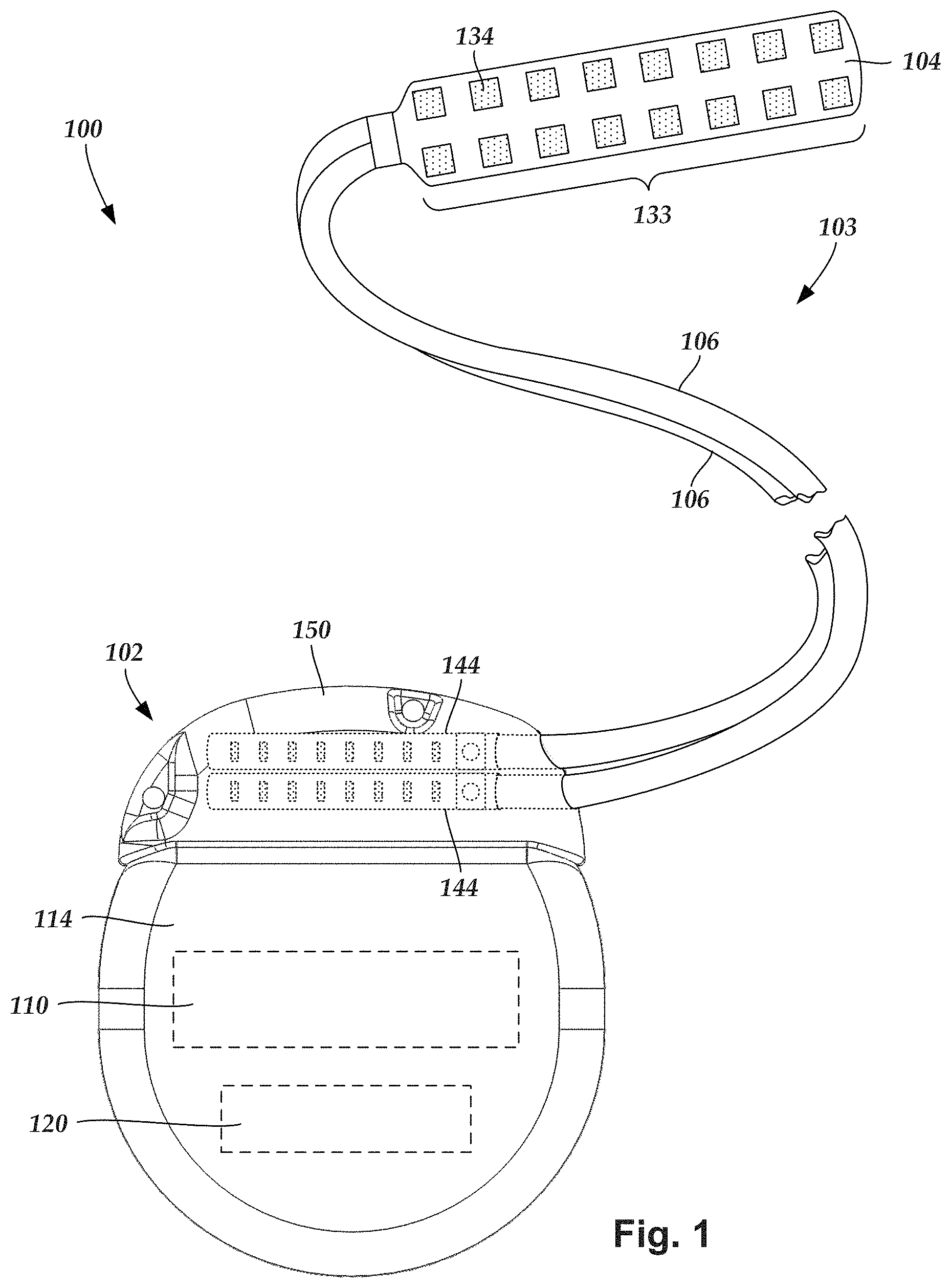
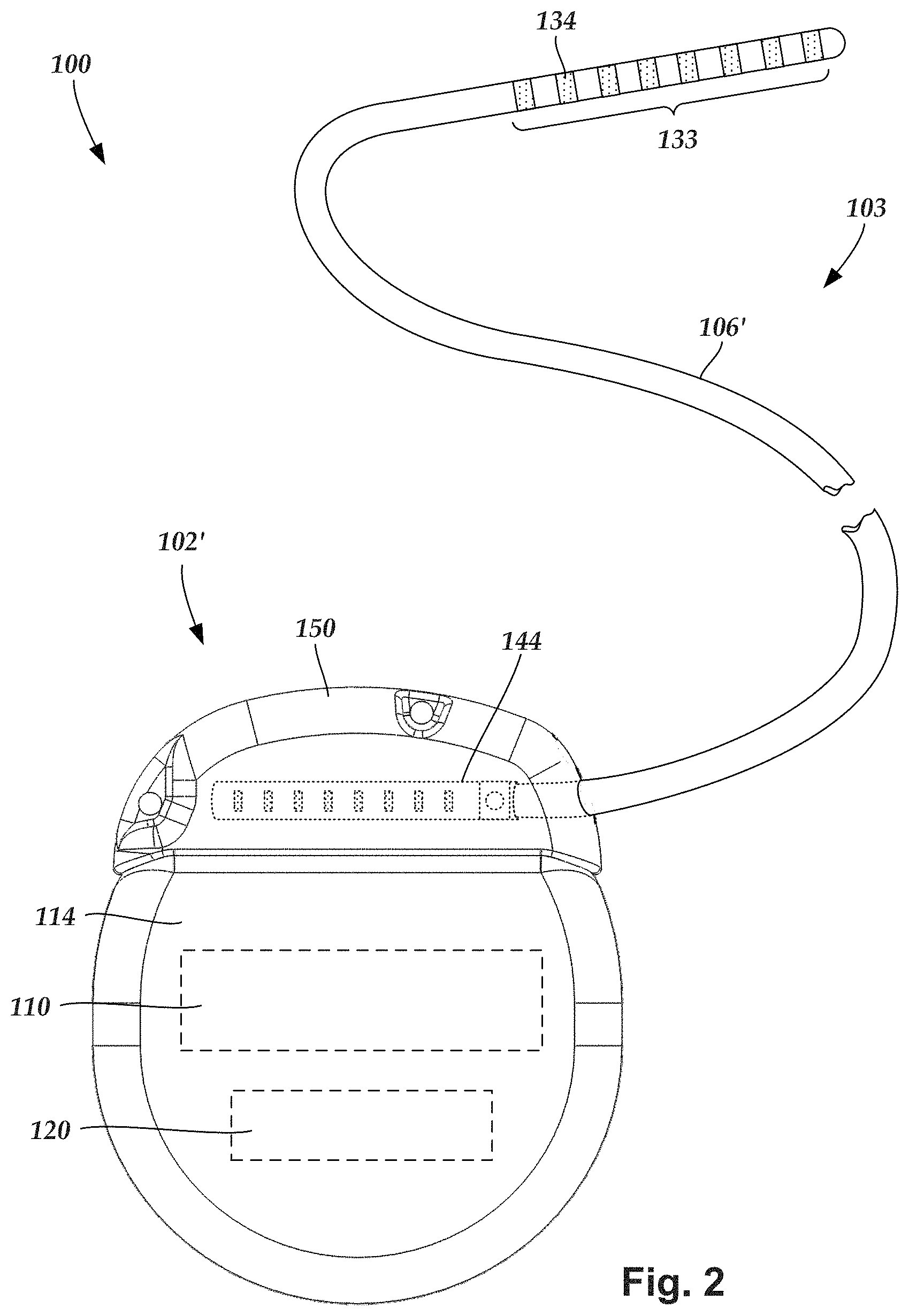
FIG. 1 is a schematic view of one embodiment of an electrical stimulation system that includes a paddle body coupled to a control module via lead bodies, according to the invention;
FIG. 2 is a schematic view of another embodiment of an electrical stimulation system that includes a percutaneous lead body coupled to a control module via a lead body, according to the invention;
FIG. 3A is a schematic view of one embodiment of a plurality of connector assemblies disposed in the control module of FIG. 1, the connector assemblies configured and arranged to receive the proximal portions of the lead bodies of FIG. 1, according to the invention;
FIG. 3B is a schematic view of one embodiment of a connector assembly disposed in the control module of FIG. 2, the connector assembly configured and arranged to receive the proximal portion of one of the lead body of FIG. 2, according to the invention;
FIG. 3C is a schematic view of one embodiment of a proximal portion of the lead body of FIG. 2, a lead extension, and the control module of FIG. 2, the lead extension configured and arranged to couple the lead body to the control module, according to the invention;
FIG. 4 is a schematic, perspective view of a lead or lead extension with a mechanical stop according to at least some embodiments of the present invention;
FIG. 5 is a schematic, perspective view of a lead assembly with a lead or lead extension having a mechanical stop inserted into a contact housing according to at least some embodiments of the present invention;
FIG. 6 is a schematic, cross-sectional view of the mechanical stop of FIG. 4 and a schematic, side-elevational view of a connector block with the contact housing of FIG. 5 according to at least some embodiments of the present invention;
FIG. 7 is a schematic, perspective view of a lead assembly with a lead or lead extension having a visually distinctive marking being inserted into a contact housing according to at least some embodiments of the present invention;
FIG. 8 is a schematic, perspective view of the lead assembly of FIG. 7 with the visually distinctive marking fully inserted into the contact housing;
FIG. 9 is a schematic, perspective view of the lead assembly of FIG. 7 with the visually distinctive marking not yet fully inserted into the contact housing; and
FIG. 10 is a schematic overview of one embodiment of components of a stimulation system, including an electronic subassembly disposed within a control module, according to the invention.
DETAILED DESCRIPTION
The present invention is directed to the area of implantable electrical stimulation systems and methods of making and using the systems. The present invention is also directed to implantable electrical stimulation leads having biased ball-spring type contacts and connect assemblies, as well as methods of making and using the contacts, contact assemblies, and the electrical stimulation systems.
Suitable implantable electrical stimulation systems include, but are not limited to, a least one lead with one or more electrodes disposed along a distal end of the lead and one or more terminals disposed along the one or more proximal ends of the lead. Leads include, for example, percutaneous leads, paddle leads, and cuff leads. Examples of electrical stimulation systems with leads are found in, for example, U.S. Pat. Nos. 6,181,969; 6,295,944; 6,391,985; 6,516,227; 6,609,029; 6,609,032; 6,741,892; 7,244,150; 7,450,997; 7,672,734; 7,761,165; 7,783,359; 7,792,590; 7,809,446; 7,949,395; 7,974,706; 8,831,742; 8,688,235; 6,175,710; 6,224,450; 6,271,094; 6,295,944; 6,364,278; and 6,391,985; U.S. Patent Applications Publication Nos. 2007/0150036; 2009/0187222; 2009/0276021; 2010/0076535; 2010/0268298; 2011/0004267; 2011/0078900; 2011/0130817; 2011/0130818; 2011/0238129; 2011/0313500; 2012/0016378; 2012/0046710; 2012/0071949; 2012/0165911; 2012/0197375; 2012/0203316; 2012/0203320; 2012/0203321; 2012/0316615; 2013/0105071; 2011/0005069; 2010/0268298; 2011/0130817; 2011/0130818; 2011/0078900; 2011/0238129; 2011/0313500; 2012/0016378; 2012/0046710; 2012/0165911; 2012/0197375; 2012/0203316; 2012/0203320; and 2012/0203321, all of which are incorporated by reference in their entireties.
Examples of connectors, connector contacts and connector assemblies for electrical stimulation systems with leads are found in, for example, U.S. Pat. Nos. 8,849,396; 7,244,150; 8,600,507; 8,897,876; 8,682,439; U.S. Patent Applications Publication Nos. 2012/0053646; 2014/0148885; 2015/0209575; 2016/0059019; and U.S. Patent Provisional Patent Application Nos. 62/193,472; 62/216,594; 62/259,463; and 62/278,667, all of which are incorporated by reference in their entireties.
FIG. 1 illustrates schematically one embodiment of an electrical stimulation system 100. The electrical stimulation system includes a control module (e.g., a stimulator or pulse generator) 102 and a lead 103. The lead 103 including a paddle body 104 and one or more lead bodies 106 coupling the control module 102 to the paddle body 104. The paddle body 104 and the one or more lead bodies 106 form the lead 103. The paddle body 104 typically includes a plurality of electrodes 134 that form an array of electrodes 133. The control module 102 typically includes an electronic subassembly 110 and an optional power source 120 disposed in a sealed housing 114. In FIG. 1, two lead bodies 106 are shown coupled to the control module 102.
The control module 102 typically includes one or more connector assemblies 144 into which the proximal end of the one or more lead bodies 106 can be plugged to make an electrical connection via connector contacts (e.g., 316 in FIG. 3A) disposed in the connector assembly 144 and terminals (e.g., 310 in FIG. 3A) on each of the one or more lead bodies 106. The connector contacts are coupled to the electronic subassembly 110 and the terminals are coupled to the electrodes 134. In FIG. 1, two connector assemblies 144 are shown.
The one or more connector assemblies 144 may be disposed in a header 150. The header 150 provides a protective covering over the one or more connector assemblies 144. The header 150 may be formed using any suitable process including, for example, casting, molding (including injection molding), and the like. In addition, one or more lead extensions 324 (see FIG. 3C) can be disposed between the one or more lead bodies 106 and the control module 102 to extend the distance between the one or more lead bodies 106 and the control module 102.
It will be understood that the electrical stimulation system can include more, fewer, or different components and can have a variety of different configurations including those configurations disclosed in the electrical stimulation system references cited herein. For example, instead of a paddle body 104, the electrodes 134 can be disposed in an array at or near the distal end of a lead body 106' forming a percutaneous lead 103, as illustrated in FIG. 2. The percutaneous lead may be isodiametric along the length of the lead body 106''. The lead body 106' can be coupled with a control module 102' with a single connector assembly 144.
The electrical stimulation system or components of the electrical stimulation system, including one or more of the lead bodies 106, the control module 102, and, in the case of a paddle lead, the paddle body 104, are typically implanted into the body of a patient. The electrical stimulation system can be used for a variety of applications including, but not limited to, spinal cord stimulation, brain stimulation, neural stimulation, muscle activation via stimulation of nerves innervating muscle, and the like.
The electrodes 134 can be formed using any conductive, biocompatible material. Examples of suitable materials include metals, alloys, conductive polymers, conductive carbon, and the like, as well as combinations thereof. In at least some embodiments, one or more of the electrodes 134 are formed from one or more of: platinum, platinum iridium, palladium, titanium, or rhenium.
The number of electrodes 134 in the array of electrodes 133 may vary. For example, there can be two, three, four, five, six, seven, eight, nine, ten, eleven, twelve, thirteen, fourteen, fifteen, sixteen, or more electrodes 134. As will be recognized, other numbers of electrodes 134 may also be used. In FIG. 1, sixteen electrodes 134 are shown. The electrodes 134 can be formed in any suitable shape including, for example, round, oval, triangular, rectangular, pentagonal, hexagonal, heptagonal, octagonal, or the like.
The electrodes of the paddle body 104 or one or more lead bodies 106 are typically disposed in, or separated by, a non-conductive, biocompatible material including, for example, silicone, polyurethane, and the like or combinations thereof. The paddle body 104 and one or more lead bodies 106 may be formed in the desired shape by any process including, for example, molding (including injection molding), casting, and the like. Electrodes and connecting wires can be disposed onto or within a paddle body either prior to or subsequent to a molding or casting process. The non-conductive material typically extends from the distal end of the lead 103 to the proximal end of each of the one or more lead bodies 106. The non-conductive, biocompatible material of the paddle body 104 and the one or more lead bodies 106 may be the same or different. The paddle body 104 and the one or more lead bodies 106 may be a unitary structure or can be formed as two separate structures that are permanently or detachably coupled together.
Terminals (e.g., 310 in FIG. 3A) are typically disposed at the proximal end of the one or more lead bodies 106 for connection to corresponding conductive contacts (e.g., 316 in FIG. 3A) in connector assemblies (e.g., 144 in FIG. 1) disposed on, for example, the control module 102 (or to other devices, such as conductive contacts on a lead extension, an operating room cable, a splitter, an adaptor, or the like).
Conductive wires (not shown) extend from the terminals (e.g., 310 in FIG. 3A) to the electrodes 134. Typically, one or more electrodes 134 are electrically coupled to a terminal (e.g., 310 in FIG. 3A). In some embodiments, each terminal (e.g., 310 in FIG. 3A) is only coupled to one electrode 134.
The conductive wires may be embedded in the non-conductive material of the lead or can be disposed in one or more lumens (not shown) extending along the lead. In some embodiments, there is an individual lumen for each conductive wire. In other embodiments, two or more conductive wires may extend through a lumen. There may also be one or more lumens (not shown) that open at, or near, the proximal end of the lead, for example, for inserting a stylet rod to facilitate placement of the lead within a body of a patient. Additionally, there may also be one or more lumens (not shown) that open at, or near, the distal end of the lead, for example, for infusion of drugs or medication into the site of implantation of the paddle body 104. The one or more lumens may, optionally, be flushed continually, or on a regular basis, with saline, epidural fluid, or the like. The one or more lumens can be permanently or removably sealable at the distal end.
As discussed above, the one or more lead bodies 106 may be coupled to the one or more connector assemblies 144 disposed on the control module 102. The control module 102 can include any suitable number of connector assemblies 144 including, for example, two three, four, five, six, seven, eight, or more connector assemblies 144. It will be understood that other numbers of connector assemblies 144 may be used instead. In FIG. 1, each of the two lead bodies 106 includes eight terminals that are shown coupled with eight conductive contacts disposed in a different one of two different connector assemblies 144.
FIG. 3A is a schematic side view of one embodiment of a plurality of connector assemblies 144 disposed on the control module 102. In at least some embodiments, the control module 102 includes two connector assemblies 144. In at least some embodiments, the control module 102 includes four connector assemblies 144. In FIG. 3A, proximal ends 306 of the plurality of lead bodies 106 are shown configured and arranged for insertion to the control module 102. FIG. 3B is a schematic side view of one embodiment of a single connector assembly 144 disposed on the control module 102'. In FIG. 3B, the proximal end 306 of the single lead body 106' is shown configured and arranged for insertion to the control module 102'.
In FIGS. 3A and 3B, the one or more connector assemblies 144 are disposed in the header 150. In at least some embodiments, the header 150 defines one or more ports 304 into which the proximal end(s) 306 of the one or more lead bodies 106/106' with terminals 310 can be inserted, as shown by directional arrows 312, in order to gain access to the connector contacts disposed in the one or more connector assemblies 144.
The one or more connector assemblies 144 each include a connector housing 314 and a plurality of connector contacts 316 disposed therein. Typically, the connector housing 314 defines a port (not shown) that provides access to the plurality of connector contacts 316. In at least some embodiments, one or more of the connector assemblies 144 further includes a retaining element 318 configured and arranged to fasten the corresponding lead body 106/106' to the connector assembly 144 when the lead body 106/106' is inserted into the connector assembly 144 to prevent undesired detachment of the lead body 106/106' from the connector assembly 144. For example, the retaining element 318 may include an aperture 320 through which a fastener (e.g., a set screw, pin, or the like) may be inserted and secured against an inserted lead body 106/106'.
When the one or more lead bodies 106/106' are inserted into the one or more ports 304, the connector contacts 316 can be aligned with the terminals 310 disposed on the one or more lead bodies 106/106' to electrically couple the control module 102 to the electrodes (134 of FIG. 1) disposed at a distal end of the one or more lead bodies 106. Examples of connector assemblies in control modules are found in, for example, U.S. Pat. Nos. 7,244,150 and 8,224,450, which are incorporated by reference.
In at least some embodiments, the electrical stimulation system includes one or more lead extensions. The one or more lead bodies 106/106' can be coupled to one or more lead extensions which, in turn, are coupled to the control module 102/102'. In FIG. 3C, a lead extension connector assembly 322 is disposed on a lead extension 324. The lead extension connector assembly 322 is shown disposed at a distal end 326 of the lead extension 324. The lead extension connector assembly 322 includes a contact housing 328. The contact housing 328 defines at least one port 330 into which a proximal end 306 of the lead body 106' with terminals 310 can be inserted, as shown by directional arrow 338. The lead extension connector assembly 322 also includes a plurality of connector contacts 340. When the lead body 106' is inserted into the port 330, the connector contacts 340 disposed in the contact housing 328 can be aligned with the terminals 310 on the lead body 106 to electrically couple the lead extension 324 to the electrodes (134 of FIG. 1) disposed at a distal end (not shown) of the lead body 106'.
The proximal end of a lead extension can be similarly configured and arranged as a proximal end of a lead body. The lead extension 324 may include a plurality of conductive wires (not shown) that electrically couple the connector contacts 340 to terminal on a proximal end 348 of the lead extension 324. The conductive wires disposed in the lead extension 324 can be electrically coupled to a plurality of terminals (not shown) disposed on the proximal end 348 of the lead extension 324. In at least some embodiments, the proximal end 348 of the lead extension 324 is configured and arranged for insertion into a lead extension connector assembly disposed in another lead extension. In other embodiments (as shown in FIG. 3C), the proximal end 348 of the lead extension 324 is configured and arranged for insertion into the connector assembly 144 disposed on the control module 102'.
It will be understood that the control modules 102/102' can receive either lead bodies 106/106' or lead extensions 324. It will also be understood that the electrical stimulation system 100 can include a plurality of lead extensions 224. For example, each of the lead bodies 106 shown in FIGS. 1 and 3A can, alternatively, be coupled to a different lead extension 224 which, in turn, are each coupled to different ports of a two-port control module, such as the control module 102 of FIGS. 1 and 3A.
In at least some conventional electrical stimulation systems, coupling a neuromodulation lead (or lead extension) to a device such as, but not limited to, a lead extension, a splitter, an adapter, a connector, an implantable pulse generator (IPG) header, is accomplished by longitudinally aligning the terminals of the lead (or lead extension) with the contacts of the device. Misalignment of the terminals vis-a-vis the contacts may occur because (1) the lead is not fully inserted into the device or (2) because the lead is pushed too far into the device. By way of example, pushing the lead too far into a connector housing may cause the housing to stretch, thus creating a misalignment between the terminals on the lead and the contacts within the connector housing.
To confirm proper alignment, a mechanical stop located distally from the terminals of the lead can be coupled to, or integrally formed with the lead. The mechanical stop includes an outside diameter larger than an inner diameter of the connector or connector block into which the lead is being inserted. This difference in diameters or interference can provide a hard stop to halt further insertion of the lead into the connector. Additionally or alternatively, proper alignment may be confirmed by using a visually distinctive marking or band applied on the lead and also located distally from the terminals of the lead. The marking or band would provide a visual indication and confirmation that the lead is inserted to the proper depth into the connector. Although the present description refers to a lead, it will be understood that the mechanical stop or visually distinctive marking can also be applied to a lead extension to facilitate alignment of the terminals of the lead extension with contacts in a connector. In addition, the connector described herein can be the connector on a lead extension, adapter, splitter, implantable pulse generator, or any other connector for a lead or lead extension in an electrical stimulation system.
FIG. 4 shows a schematic, perspective view of a portion of a proximal end 402 of a lead or lead extension 401. A plurality of terminals 406 are arranged along the proximal end 402. The terminals 406 may take the form of terminals 310 in FIG. 3C. Optionally, a retention sleeve 408 is coupled to the lead or lead extension 401 and located distally from the terminals 406. Further, a mechanical stop 410 is coupled to the lead or lead extension 401 distally from the terminals 406. In at least some embodiments, the mechanical stop 410 is slid onto the lead or lead extension and mechanically coupled thereto (for example, bonded or adhered, press fit, shrink fit, or the like) adjacent or spaced-apart from the terminals 406. In at least some other embodiments, the mechanical stop 410 can be part of the retention sleeve 408 (e.g., integrally formed with) or the mechanical stop 410 can be an extension of the retention sleeve 408.
FIG. 5 shows a schematic, perspective view of a lead assembly 400 in which a lead or lead extension 401 is inserted into a connector housing 412 of a connector, which may optionally include a connector block 414 located distally to a plurality of contacts 416 disposed within the connector housing 412. By way of example, the connector housing 412 may be similar to the contact housing 328 in FIG. 3C. The connector housing 412 is made from a non-conductive, biocompatible material including, for example, silicone, polyurethane, and the like or combinations thereof. The contacts 416 may be disposed in, or separated by, the connector housing 412 or another non-conductive, biocompatible material such as, for example, silicone, polyurethane, polyetheretherketone ("PEEK"), epoxy, and the like or combinations thereof. The contacts 416 themselves can be formed using any conductive, biocompatible material. Examples of suitable materials include metals, alloys, conductive polymers, conductive carbon, and the like, as well as combinations thereof. In at least some embodiments, one or more of the contacts are formed from one or more of: platinum, platinum iridium, palladium, palladium rhodium, or titanium.
The connector block 414 can be made from a rigid or hard material and, at least in some embodiments, is threaded to receive a set screw (FIG. 3C), which can be used to secure the lead or lead extension 401 when the set screw is placed into a set screw aperture 415 to engage the retention sleeve 408 (FIG. 4) or the lead or lead extension 401. Other methods of fixing the lead or lead extension to the connector can also be used. The connector housing 412 defines at least one port 418 into which a portion of the lead or lead extension 401 can be inserted (as shown). The port 418 leads to a through channel 424 (FIG. 6) in the connector block 414. The channel 424 may be considered to be part of or a continuation of a lumen within the connector housing 412.
FIG. 6 shows a cross-sectional view of the mechanical stop 410 and a side, elevational view of the connector block 414 as viewed from the port 418. In at least some embodiments, the mechanical stop 410 takes the form of a ring having an inner diameter 420 and an outer diameter 422. The connector block 414 includes the channel 424 that extends through the connector block 414 along an axial or longitudinal direction as indicated by arrow 426 (FIG. 5) of the lead or lead extension 401, which in turn coincides with an axial or longitudinal direction 426 (FIG. 5) of the connector housing 412. The channel 424 defines a channel diameter 428 (or lumen diameter), which is smaller than the outer diameter 422 of the mechanical stop 410. In at least some embodiments, the channel diameter 428 is at least slightly larger than the inner diameter 420 of the mechanical stop 410, but smaller than the outer diameter 422 of the mechanical stop 410. Accordingly, insertion of the lead or lead extension 401 into the connector block 414 is halted when the mechanical stop 410 physically contacts a distal surface 430 of the connector block 414 because the outer diameter 422 of the mechanical stop 410 is larger than the channel diameter 428 of the connector block 414.
Referring back to FIGS. 4 and 5, the mechanical stop 410, when in contact with a distal surface 430 (FIG. 6) of the connector block 414, can be disposed fully within the connector housing 412 between the port 418 of the contact housing and the distal surface 430 of the connector block 414. Alternatively, a portion of the mechanical stop 410 may extend outside of the connector housing 412 after the mechanical stop 410 has made physical contact with the distal surface 430 of connector block 414.
In at least some embodiments, a fastener (not shown) such as, but not limited to, a set screw, can be inserted into the connector block 414 when the mechanical stop 410 contacts the distal surface 430 of the connector block 414. The fastener securely fixes the lead or lead extension to the connector block 414 by pressing on the retention sleeve 408 or by pressing on the lead or lead extension 401. In at least some embodiments, a length of the retention sleeve 408 is equal to or greater than a distance between a proximal side of the connector block 414 and a distal side 430 of the connector block 414.
FIG. 7 shows a schematic, perspective view of a lead assembly 500 in which a lead or lead extension 501 is inserted into a connector housing 512 of a connector. In the illustrated embodiment, a visually distinctive marking 510 (such as a band) may be utilized instead of a mechanical stop 410 (FIG. 4). In at least some embodiments, the marking 510 is applied to the lead or lead extension 501 distally from the terminals of the lead or lead extension 501. The location or position of the marking 510 relative to the distal end of the connector housing 512 provides a visible indication that the plurality of terminals of the lead or lead extension are aligned with the plurality of contacts disposed in the contact housing.
By way of example, the marking 510 may indicate alignment of the plurality of terminals and the plurality of contacts when a predetermined one of the leading or trailing edge of the marking 510 longitudinally aligns with the distal end of the connector housing 512. If the trailing edge of the marking 510 is aligned with the distal end of the connector housing 512 then the marking 510 would be fully covered by the connector housing 512. Thus, insertion of the lead or lead extension 501 would be halted and secured to the connector housing 512 once the marking 510 disappeared into the connector housing 512. In another embodiment, aligning the leading edge of the marking with the distal end of the connector housing 512 would indicate that the lead or lead extension has been inserted to a proper depth within the connector housing 512.
In at least some embodiments, the marking 510 may be an extension of or applied to the optional retention sleeve.
Preferably, the marking has a color that visibly contrasts with the color of the lead or lead extension 501 and further visibly contrasts with the color of the connector housing 512.
FIG. 8 shows a schematic, perspective view of the lead assembly 500 in which the marking 510 has been inserted enough to be fully covered by the connector housing 512. In this embodiment, the terminals of the lead or lead extension 501 are longitudinally aligned with the contacts disposed within the connector housing 512.
In contrast, FIG. 9 shows a small region of the marking 510 still exposed (i.e., not fully covered by the connector housing 512), which would indicate that the lead or lead extension 501 requires further insertion for proper alignment between the terminals and contacts can be confirmed.
FIG. 10 is a schematic overview of one embodiment of components of an electrical stimulation system 600 including an electronic subassembly 610 disposed within a control module. It will be understood that the electrical stimulation system can include more, fewer, or different components and can have a variety of different configurations including those configurations disclosed in the stimulator references cited herein.
Some of the components (for example, a power source 612, an antenna 618, a receiver 602, and a processor 604) of the electrical stimulation system can be positioned on one or more circuit boards or similar carriers within a sealed housing of an implantable pulse generator, if desired. Any power source 612 can be used including, for example, a battery such as a primary battery or a rechargeable battery. Examples of other power sources include super capacitors, nuclear or atomic batteries, mechanical resonators, infrared collectors, thermally-powered energy sources, flexural powered energy sources, bioenergy power sources, fuel cells, bioelectric cells, osmotic pressure pumps, and the like including the power sources described in U.S. Pat. No. 7,437,193, incorporated herein by reference.
As another alternative, power can be supplied by an external power source through inductive coupling via the optional antenna 618 or a secondary antenna. The external power source can be in a device that is mounted on the skin of the user or in a unit that is provided near the user on a permanent or periodic basis.
If the power source 612 is a rechargeable battery, the battery may be recharged using the optional antenna 618, if desired. Power can be provided to the battery for recharging by inductively coupling the battery through the antenna to a recharging unit 616 external to the user. Examples of such arrangements can be found in the references identified above.
In one embodiment, electrical current is emitted by the electrodes 134 on the paddle or lead body to stimulate nerve fibers, muscle fibers, or other body tissues near the electrical stimulation system. The processor 604 is generally included to control the timing and electrical characteristics of the electrical stimulation system. For example, the processor 604 can, if desired, control one or more of the timing, frequency, strength, duration, and waveform of the pulses. In addition, the processor 604 can select which electrodes can be used to provide stimulation, if desired. In some embodiments, the processor 604 selects which electrode(s) are cathodes and which electrode(s) are anodes. In some embodiments, the processor 604 is used to identify which electrodes provide the most useful stimulation of the desired tissue.
Any processor can be used and can be as simple as an electronic device that, for example, produces pulses at a regular interval or the processor can be capable of receiving and interpreting instructions from an external programming unit 608 that, for example, allows modification of pulse characteristics. In the illustrated embodiment, the processor 604 is coupled to a receiver 602 which, in turn, is coupled to the optional antenna 618. This allows the processor 604 to receive instructions from an external source to, for example, direct the pulse characteristics and the selection of electrodes, if desired.
In one embodiment, the antenna 618 is capable of receiving signals (e.g., RF signals) from an external telemetry unit 606 which is programmed by the programming unit 608. The programming unit 608 can be external to, or part of, the telemetry unit 606. The telemetry unit 606 can be a device that is worn on the skin of the user or can be carried by the user and can have a form similar to a pager, cellular phone, or remote control, if desired. As another alternative, the telemetry unit 606 may not be worn or carried by the user but may only be available at a home station or at a clinician's office. The programming unit 608 can be any unit that can provide information to the telemetry unit 606 for transmission to the electrical stimulation system 600. The programming unit 608 can be part of the telemetry unit 606 or can provide signals or information to the telemetry unit 606 via a wireless or wired connection. One example of a suitable programming unit is a computer operated by the user or clinician to send signals to the telemetry unit 606.
The signals sent to the processor 604 via the antenna 618 and the receiver 602 can be used to modify or otherwise direct the operation of the electrical stimulation system. For example, the signals may be used to modify the pulses of the electrical stimulation system such as modifying one or more of pulse duration, pulse frequency, pulse waveform, and pulse strength. The signals may also direct the electrical stimulation system 600 to cease operation, to start operation, to start charging the battery, or to stop charging the battery. In other embodiments, the stimulation system does not include the antenna 618 or receiver 602 and the processor 604 operates as programmed.
Optionally, the electrical stimulation system 600 may include a transmitter (not shown) coupled to the processor 604 and the antenna 618 for transmitting signals back to the telemetry unit 606 or another unit capable of receiving the signals. For example, the electrical stimulation system 600 may transmit signals indicating whether the electrical stimulation system 600 is operating properly or not or indicating when the battery needs to be charged or the level of charge remaining in the battery. The processor 604 may also be capable of transmitting information about the pulse characteristics so that a user or clinician can determine or verify the characteristics.
The above specification provides a description of the structure, manufacture, and use of the invention. Since many embodiments of the invention can be made without departing from the spirit and scope of the invention, the invention also resides in the claims hereinafter appended.
* * * * *
D00000
D00001
D00002
D00003
D00004
D00005
D00006
D00007
D00008
XML
uspto.report is an independent third-party trademark research tool that is not affiliated, endorsed, or sponsored by the United States Patent and Trademark Office (USPTO) or any other governmental organization. The information provided by uspto.report is based on publicly available data at the time of writing and is intended for informational purposes only.
While we strive to provide accurate and up-to-date information, we do not guarantee the accuracy, completeness, reliability, or suitability of the information displayed on this site. The use of this site is at your own risk. Any reliance you place on such information is therefore strictly at your own risk.
All official trademark data, including owner information, should be verified by visiting the official USPTO website at www.uspto.gov. This site is not intended to replace professional legal advice and should not be used as a substitute for consulting with a legal professional who is knowledgeable about trademark law.