Play table with tablet adjustor mechanism
Pettersson , et al. February 2, 2
U.S. patent number 10,905,250 [Application Number 16/282,387] was granted by the patent office on 2021-02-02 for play table with tablet adjustor mechanism. This patent grant is currently assigned to Volvo Car Corporation. The grantee listed for this patent is Volvo Car Corporation. Invention is credited to Conny Blomme, Jonas Gothlin, Eric Gunnarsson Hornsten, Matilda Johansson, Hanna Pettersson, Fredrik Strahlin.


| United States Patent | 10,905,250 |
| Pettersson , et al. | February 2, 2021 |
Play table with tablet adjustor mechanism
Abstract
A play table includes a base member, a door member, and a rotatable adjustor mechanism for securely holding items of different sizes on the play table. The base member includes side walls and a top wall extending between the side walls to form a storage compartment therein. The top wall includes a recessed, exterior, working surface. The door member is hingedly connected to one of the side walls for selectively opening and closing the storage compartment. The adjustor mechanism is rotatably attached to the top wall and includes an upper retention member, a lower mounting member, and a spring-loaded shaft member. The adjustor mechanism is spring-loaded to provide a biasing force against the item placed on the working surface to securely hold the item on the play table.
| Inventors: | Pettersson; Hanna (Gothenburg, SE), Hornsten; Eric Gunnarsson (Gothenburg, SE), Gothlin; Jonas (Gothenburg, SE), Blomme; Conny (Gothenburg, SE), Johansson; Matilda (Gothenburg, SE), Strahlin; Fredrik (Gothenburg, SE) | ||||||||||
|---|---|---|---|---|---|---|---|---|---|---|---|
| Applicant: |
|
||||||||||
| Assignee: | Volvo Car Corporation
(Goteborg, SE) |
||||||||||
| Family ID: | 1000005333288 | ||||||||||
| Appl. No.: | 16/282,387 | ||||||||||
| Filed: | February 22, 2019 |
Prior Publication Data
| Document Identifier | Publication Date | |
|---|---|---|
| US 20200268167 A1 | Aug 27, 2020 | |
| Current U.S. Class: | 1/1 |
| Current CPC Class: | A47B 23/06 (20130101); A47D 3/00 (20130101); A47B 23/002 (20130101) |
| Current International Class: | A47D 3/00 (20060101); A47B 23/06 (20060101); A47B 23/00 (20060101) |
| Field of Search: | ;108/25,42-44 ;248/451-453,444 ;190/11 |
References Cited [Referenced By]
U.S. Patent Documents
| 1797889 | March 1931 | Wiberg |
| 2489553 | November 1949 | Henderson |
| 2628659 | February 1953 | Carpenter |
| 3104895 | September 1963 | Feuerbach et al. |
| 3338629 | August 1967 | Drees |
| 3408032 | October 1968 | Francis |
| 3983976 | October 1976 | Taylor |
| 4053133 | October 1977 | Kauffman |
| 4483427 | November 1984 | Gerch |
| 4531642 | July 1985 | Racich |
| 4553728 | November 1985 | Corsello |
| 4619386 | October 1986 | Richardson |
| 4702453 | October 1987 | Bishop |
| 4815623 | March 1989 | Levin |
| 4892334 | January 1990 | Sinclair |
| 5115893 | May 1992 | Terkildsen |
| 5797578 | August 1998 | Graffeo |
| 5894922 | April 1999 | Miller et al. |
| 6173656 | January 2001 | Blanchard |
| 8393584 | March 2013 | Burns |
| 8746156 | June 2014 | Camarillo |
| 8770536 | July 2014 | Hu |
| 8910838 | December 2014 | Palmer et al. |
| 8925886 | January 2015 | Sears |
| D753766 | April 2016 | Chuang |
| 9743759 | November 2017 | Ramirez et al. |
| 9999298 | June 2018 | Sullins |
| 2004/0163913 | August 2004 | Tschudy |
| 2005/0285009 | December 2005 | Phifer |
| 2006/0174530 | August 2006 | Chang |
| 2007/0125926 | June 2007 | Phifer |
| 2009/0045314 | February 2009 | Lien |
| 2010/0019118 | January 2010 | Nagpal |
| 2011/0127304 | June 2011 | Kam |
| 2012/0212896 | August 2012 | Schulz |
| 2465438 | Mar 1981 | FR | |||
| 2014101235 | Jul 2014 | WO | |||
Attorney, Agent or Firm: Clements Bernard Walker Bernard; Christopher L.
Claims
The invention claimed is:
1. A play table for holding and storing an item, the play table comprising: a base member comprising a first pair of opposing side walls, a second pair of opposing side walls, and a top wall extending between the first and second pairs of opposing side walls to define a storage compartment therebetween; a door member disposed opposite the top wall and hingedly connected to one wall of the first and second pairs of opposing side walls, the door member adapted to provide access to the storage compartment; and an adjustor mechanism rotatably coupled to the top wall, the adjustor mechanism adapted to securely hold the item when the item is placed on an exterior surface of the top wall of the play table; wherein one wall of the second pair of opposing side walls has a height, H, that is greater than a height, H, of another wall of the second pair of opposing side walls.
2. The play table of claim 1, wherein the adjustor mechanism comprises one of a spring mechanism and a damper mechanism adapted to provide a biasing force against the item when the item is placed on the exterior surface of the top wall of the play table.
3. The play table of claim 1, wherein the adjustor mechanism comprises an upper retention member, a lower mounting member, and a shaft member disposed therebetween.
4. The play table of claim 3, wherein the upper retention member is disposed proximate the exterior surface of the top wall, the lower mounting member is coupled to an interior surface of the top wall, and the shaft member is disposed through the top wall.
5. The play table of claim 3, wherein the upper retention member comprises an upper portion and a lower portion, the upper portion having a width that is greater than a width of the lower portion such that the upper portion overhangs the lower portion.
6. The play table of claim 5, wherein lower portion of the upper retention member and the top wall define a gap when the adjustor mechanism is rotatably coupled to the top wall.
7. The play table of claim 5, wherein the upper portion of the upper retention member is adapted to overlap a portion of the item the lower portion of the upper retention member is adapted to contact a portion of the item when the adjustor mechanism is placed in an actuated position.
8. The play table of claim 1, wherein the top surface comprises a raised ledge disposed about a perimeter of the exterior surface thereof.
9. The play table of claim 1, wherein the door member defines a cutout adapted to receive one or more fingers of a user for transporting the play table.
10. The play table of claim 1, wherein the first pair of opposing side walls are substantially identical in shape and have a height, H, that continuously varies along a length, L, thereof.
11. A play table for holding and storing an item, the play table comprising: a base member comprising a first pair of opposing side walls, a second pair of opposing side walls, and a top wall extending between the first and second pairs of opposing side walls to define a storage compartment therebetween; a door member disposed opposite the top wall, wherein the door member is integrally formed with and hingedly connected to one wall of the second pair of opposing side walls, the door member adapted to provide access to the storage compartment; and an adjustor mechanism rotatably coupled to the top wall, the adjustor mechanism adapted to securely hold the item when the item is placed on an exterior surface of the top wall of the play table; wherein the first pair of opposing side walls are substantially identical in shape and have a height, H, that continuously varies along a length, L, thereof, and wherein one wall of the second pair of opposing side walls has a height, H, that is greater than a height, H, of another wall of the second pair of opposing side walls.
12. The play table of claim 11, wherein the adjustor mechanism comprises one of a spring mechanism and a damper mechanism adapted to provide a biasing force against the item when the item is placed on the exterior surface of the top wall of the play table.
13. The play table of claim 11, wherein the adjustor mechanism comprises an upper retention member, a lower mounting member, and a shaft member disposed therebetween.
14. The play table of claim 13, wherein the upper retention member is disposed proximate the exterior surface of the top wall, the lower mounting member is coupled to an interior surface of the top wall, and the shaft member is disposed through the top wall.
15. The play table of claim 13, wherein the upper retention member comprises an upper portion and a lower portion, the upper portion having a width that is greater than a width of the lower portion such that the upper portion overhangs the lower portion.
16. The play table of claim 15, wherein lower portion of the upper retention member and the top wall define a gap when the adjustor mechanism is rotatably coupled to the top wall.
17. The play table of claim 15, wherein the upper portion of the upper retention member is adapted to overlap a portion of the item the lower portion of the upper retention member is adapted to contact a portion of the item when the adjustor mechanism is placed in an actuated position.
18. The play table of claim 11, wherein the top surface comprises a raised ledge disposed about a perimeter of the exterior surface thereof.
19. An adaptor mechanism for securing an item to a play table, the adaptor mechanism comprising: an upper retention member adapted to engage the item when the item is disposed on an exterior surface of a top wall of the play table; a lower mounting member adapted to be coupled to the top wall of the play table; and a rotatable shaft member disposed between the upper retention member and the lower mounting member; wherein the upper retention member comprises an upper portion and a lower portion both extending from the rotatable shaft member and disposed along a longitudinal axis aligned perpendicular to an axis of rotation of the rotatable shaft member, wherein the upper portion has a width that is greater than a width of the lower portion such that the upper portion overhangs the lower portion.
20. The play table of claim 19, further comprising a spring mechanism coupling the rotatable shaft member to the lower mounting member, the spring mechanism adapted to provide a biasing force against the item when the item is disposed on the exterior surface of the top wall of the play table.
Description
TECHNICAL FIELD
The present invention relates generally to a play table for use in a vehicle or the like. More specifically, the present invention relates to a play table with a tablet adjustor mechanism for holding a tablet or the like.
BACKGROUND ART
While traveling in a vehicle, for example, people allow children in the back seat play with various items, such as electronic devices and the like. One reason is to provide entertainment for the children in an attempt to travel farther without hearing complaints from the back seat. During use, the electronic device, such as a tablet or the like, is usually positioned directly on the lap of the user, in an awkward ergonomic position, particularly related to the neck and back. In addition, the electronic devices may be spread all over the back seat when not in use, resulting in damage.
One solution to these problems is to provide a play table or cushion that is rested on the user's lap and tilts the tablet toward the user to provide a better ergonomic position. One such conventional play table uses a standard clip mechanism to hold the tablet in place when in use. Although this solution is simple to use, the clip mechanism cannot accommodate items, such as electronic devices and the like, of different sizes. Further no organization or storage capability is provided.
SUMMARY
The problem of accommodating items of different sizes for use with a play table is solved by providing a spring-loaded adjustor mechanism that is rotatably attached to a top surface of the play table that is capable of securely holding items of different sizes when the items are placed on the play table. The play table has an ergonomic wedge shape to angle the items towards the user and the bottom surface, which can serve as a play surface, opens to reveal a storage compartment inside. One or more storage pockets are provided in the storage compartment for holding smaller items. The play table includes a strap for easy over-the-shoulder transport of the play table and any items stored in the storage compartment.
In one exemplary embodiment, the play table for holding and storing an item provided herein includes: a base member including a first pair of opposing side walls, a second pair of opposing side walls, and a top wall extending between the first and second pairs of opposing side walls to define a storage compartment therebetween; a door member disposed opposite the top wall and hingedly connected to, and optionally integrally formed with, one wall of the first and second pairs of opposing side walls, the door member adapted to provide access to the storage compartment; and an adjustor mechanism rotatably coupled to the top wall, the adjustor mechanism adapted to securely hold the item when the item is placed on an exterior surface of the top wall of the play table. The adjustor mechanism includes one of a spring mechanism and a damper mechanism adapted to provide a biasing force against the item when the item is placed on the exterior surface of the top wall of the play table. The adjustor mechanism includes an upper retention member, a lower mounting member, and a shaft member disposed therebetween.
In another exemplary embodiment, the adaptor mechanism for securing an item to a play table provided herein includes: an upper retention member adapted to engage the item when the item is disposed on an exterior surface of a top wall of the play table; a lower mounting member adapted to be coupled to the top wall of the play table; and a rotatable shaft member disposed between the upper retention member and the lower mounting member. The adaptor mechanism also includes a spring mechanism coupling the rotatable shaft member to the lower mounting member, the spring mechanism adapted to provide a biasing force against the item when the item is disposed on the exterior surface of the top wall of the play table. The upper retention member includes an upper portion and a lower portion, the upper portion having a width that is greater than a width of the lower portion such that the upper portion overhangs the lower portion.
BRIEF DESCRIPTION OF THE DRAWINGS
While various embodiments of the invention are illustrated, the particular embodiments shown should not be construed to limit the claims. It is anticipated that various changes and modifications may be made without departing from the scope of the invention.
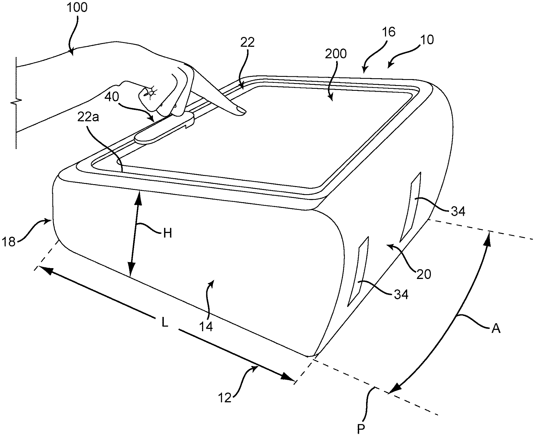
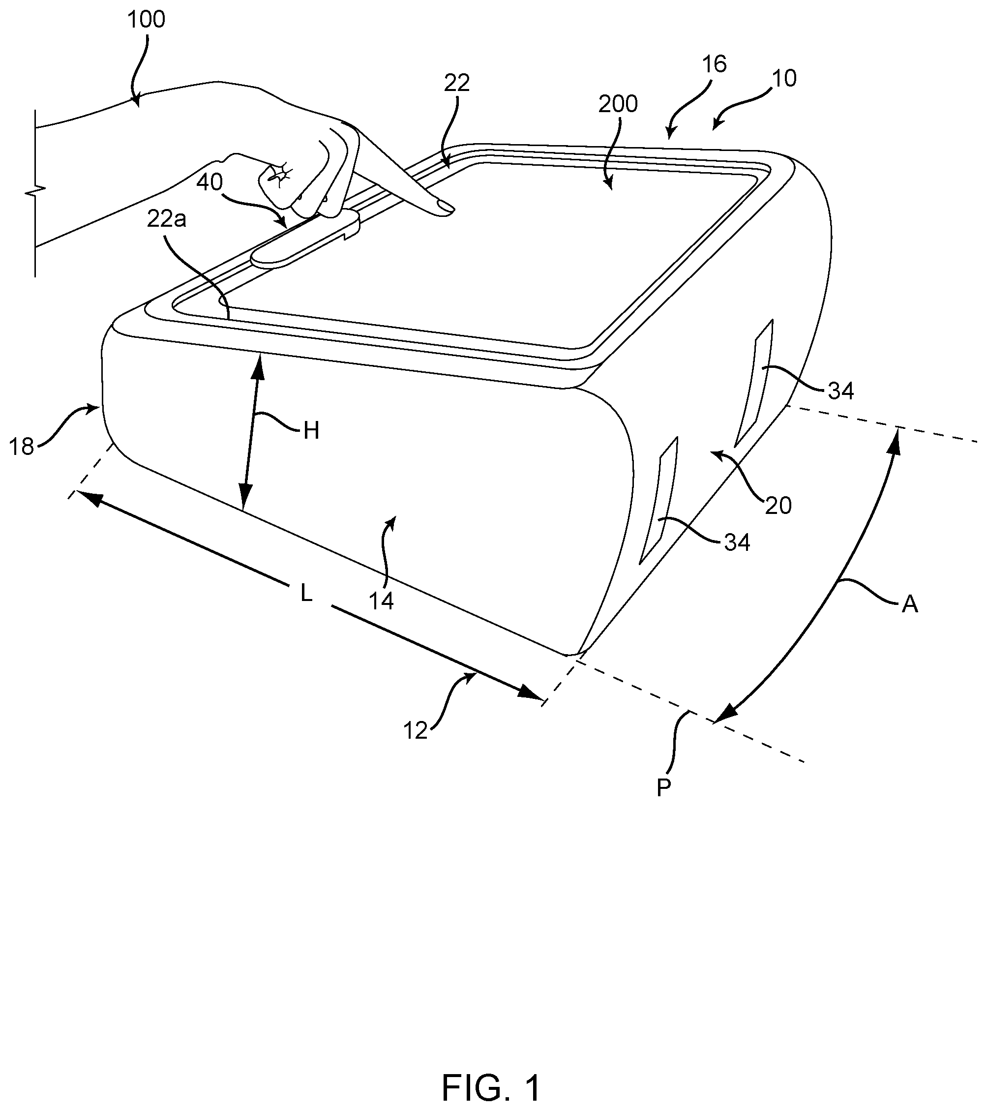
FIG. 1 is a top perspective view of a play table including a rotatable adjustor mechanism for accommodating items of different sizes (in use) according to an embodiment of the invention;
FIG. 2 is a top perspective view of the play table of FIG. 1 showing the adjustor mechanism when in at-rest position;
FIG. 3 is a bottom perspective view of the play table of FIG. 1 when the door member is in a closed position;
FIG. 4 is a bottom perspective view of the play table of FIG. 1 showing the internal storage compartment for storing items when the door member is in an open position;
FIG. 5 is a top perspective view of the rotatable adjustor mechanism according to an embodiment of the invention;
FIG. 6 is a side view of the rotatable adjustor mechanism of FIG. 5 when attached to the top surface of the play table;
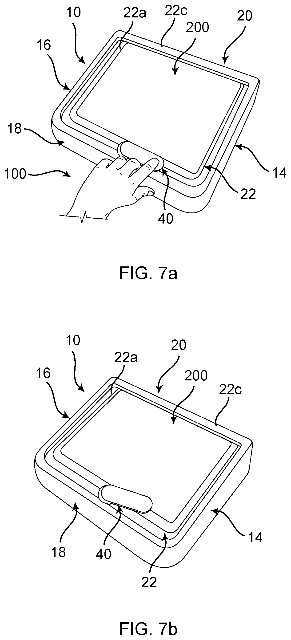
FIGS. 7(a) and 7(b) are top perspective views of the play table of FIG. 1 showing a method of securely holding an item, such as a large tablet, on the play table by moving the rotatable adjustor mechanism from a non-actuated position to an actuated position, respectively; and
FIGS. 8(a) and 8(b) are top perspective views of the play table of FIG. 1 showing a method of securely holding an item, such as a small tablet, on the play table by moving the rotatable adjustor mechanism from a non-actuated position to an actuated position, respectively.
DESCRIPTION OF EMBODIMENTS
Again, the problem of accommodating items of different sizes for use with a play table is solved by providing a spring-loaded adjustor mechanism that is rotatably attached to a top surface of the play table that is capable of securely holding items of different sizes when the items are placed on the play table. The play table has an ergonomic wedge shape to angle the items towards the user and the bottom surface, which can serve as a play surface, opens to reveal a storage compartment inside. Various storage pockets are provided in the storage compartment for holding smaller items. The play table includes a strap for easy over-the-shoulder transport of the play table and any items stored in the storage compartment.
Referring now to FIGS. 1-4, the play table 10 includes a base member 12 that includes a first pair of opposing side walls 14, 16, a second pair of opposing side walls 18, 20, and a top wall 22 extending between the first and second pairs of opposing side walls 14, 16, 18, 20. The first pair of opposing side walls 14, 16 are substantially parallel to each other and extend approximately perpendicularly with respect to the second pair of opposing side walls 18, 20. Similarly, the second pair of opposing side walls 18, 20 are substantially parallel to each other and extend approximately perpendicularly with respect to the first pair of opposing side walls 14, 16. Each of the side walls 14, 16, 18, 20 and the top wall 22, and any combination thereof, can be substantially planar or slightly curved (i.e., concave or convex). For example, the side wall 18 can be slightly curved, while the side walls 14, 16, and 20 and the top wall 22 can be substantially planar. As can be understood, each of the side walls 14, 16, 18, 20 and the top wall 22 are substantially quadrilateral in shape.
As shown in FIG. 1, each of the side walls 14, 16, 18, 20 have a length, L, and a height, H. In the illustrated embodiment, the first pair of opposing side walls 14, 16 are substantially identical in shape having a height, H, that continuously varies along the length, L. Specifically, the height, H, proximate the side wall 18 is less than the height, H, proximate the side wall 20. As a result, the top wall 22 is tilted at an angle, A, with respect to a horizontal plane, P, that is substantially parallel to the lap of a user 100 that contacts the play table 10 when in use. In addition, the second pair of opposing side walls 18, 20 have approximately the same length, L, but have different heights, H. Specifically, the height, H, of the side wall 18 is less than the height, H, of the side wall 20. This provides the base member 12 with the desired tapering wedge shape.
It will be appreciated that the side walls 14, 16, 18, 20 and the top wall 22 can be made of any suitable material for a play table, such as rigid foam material, an impact-resistant plastic material, or the like. For example, the first and second pairs of opposing side walls 14, 16, 18, 20 and the top wall 22 can be made of an expanded polypropylene (EPP) material using a well-known molding process. EPP foam material is desirable because of its heat resistance, elasticity, and recyclability, making it a green choice.
The top wall 22 has an exterior, working surface 22a and an opposite, interior surface 22b (FIG. 6). The exterior, working surface 22a is recessed with respect to a ledge 22c that extends the entire perimeter of the play table 10. The exterior, working surface 22a is recessed a depth, D, that is sufficient to accommodate and retain items, such as electronic devices and the like, when placed on the exterior, working surface 22a. During use, the ledge 22c acts as a stop and provides an indication to the user 100 that the item 200 is properly placed on the exterior, working surface 22a. In one example, the user 100 may place the item 200 on the exterior, working surface 22a such that the item 200 abuts the ledge 22c proximate the side wall 20 (FIGS. 7 and 8). It should be noted that the exterior, working surface 22a can be covered with the same material as the rest of the top wall 22 or it can be covered with a different material. For example, the exterior, working surface 22a of the top wall 22 can be covered with a fabric material, such as felt or the like, and the rest of the top wall 22 can be exposed EPP foam material.
The play table 10 further includes a door member 24 opposite the top wall 22 for selectively providing access to a storage compartment 26 formed by the side walls 14, 16, 18, 20 and the top wall 22. To this end, the door member 24 is hingedly connected to one of the side walls 14, 16, 18, 20. For example, in the illustrated embodiment, the door member 24 is hingedly connected to the side wall 20. One method of hingedly connecting the door member 24 to the side wall 20 is by forming a living hinge 27 between the door member 24 and the side wall 20 using a well-known molding process or the like. For example, the door member 24 and the side wall 20 can both me made of a fabric or felt material including the living hinge 27. This has the advantage of providing a comfortable surface that contacts the legs of the user. As an alternative, the side wall 20 can be a two-layer wall, with only the interior fabric or felt layer being integrally formed with the door member 24. In this case, the outer later of the side wall 20 is preferably manufactured from a more rigid material.
The door member 24 has an exterior surface 24a (FIG. 3) and an interior surface 24b (FIG. 4). The exterior surface 24a may be coated with a fabric or felt material for comfort and aesthetics. The interior surface 24b may include one or more pockets 29. The pockets 29, if more than one are used, can be the same dimensions or different dimensions. In the illustrated embodiment, one pocket 29 is generally rectangular in shape for accommodating a book or the like, while other adjacent pockets 29 are elongate in shape for accommodating objects, such as pencils, pens, crayons, markers, and the like. This configuration may, of course, vary as desired.
The door member 24 includes a cutout 28 of sufficient dimensions to allow the user 100 to insert one or more fingers into the cutout 28 for accessing the storage compartment 26 and/or transporting the play table 10. As can be understood, the storage compartment 26 can be accessed by inserting one or more fingers of the user 100 into the cutout 28 and raising the door member 24 such that the door member 24 pivots about the hinge 27 (as indicated by the arrows in FIG. 3). In addition, it can be understood that the user 100 can insert one or more fingers into the cutout 28 while the door member 24 is in the closed position (FIG. 3) to transport the play table 10. In the illustrated embodiment, the cutout 28 is rectangular in shape. However, it will be appreciated that the cutout 28 can be any desired shape, so long as the user 100 can insert one or more fingers into the cutout 28.
FIG. 4 shows the door member 24 when in an open position to provide access to the storage compartment 26. The side walls 14, 16 and the side wall 18 have a thickness, T, of sufficient dimensions to enable a recessed ledge 23 to be formed therein. In one embodiment, the recessed ledge 23 has a sufficient depth to enable the door member 24 to be substantially flush with the side walls 14, 16 and the side wall 18 when the door member 24 is in a closed position (FIG. 3). The door member 24 can be securely held in the closed position by using any well-known means. For example, the interior surface 24b of the door member 24 may include one or more metallic members 30 that each interact with a respective magnet 31 disposed within the ledge 23. When securely held in the closed position, the play table 10 may be transported using a carrying strap 32 that can be removably attached to the play table 10 using means well-known in the art. Instead of using the carrying strap 32, the play table 10 can also be transported by the user 100 inserting one or more fingers into the cutout 28, as mentioned above. It should be noted that the side wall 20 includes one or more legs 34 (FIG. 1). When transporting the play table 10 using the cutout 28, the play table 10 may be easily placed in an upright position by resting the play table 10 on the one or more legs 34.
One aspect of the invention is that the play table 10 includes a rotatable adjustor mechanism, shown generally at 40, for securely holding items of different sizes when placed on the top wall 22 of the play table 10. Referring now to FIGS. 5 and 6, the adjustor mechanism 40 is rotatable about an axis of rotation 42 disposed perpendicular to the top wall 22 such that the adjustor mechanism 40 can be easily rotated by the user 100 from a non-actuated position (FIG. 7(a)) to an actuated position (FIG. 7(b)). The rotation occurs across the exterior surface 22a of the top wall 22.
The adjustor mechanism 40 includes an upper retention member 44 located on one side of the top wall 22, a lower mounting member 46 located on the opposite side of the top wall 22 and a shaft member 48 disposed therebetween. When properly mounted on the top wall 22, the upper retention member 44 is disposed proximate the exterior surface 22a of the top wall 22, the lower mounting member 46 is disposed proximate the interior surface 22b of the top wall 22, and the shaft member 48 passes entirely through the top wall 22. Alternatively, the lower mounting member 46 is disposed on the exterior surface 22a of the top wall 22, potentially with the attached fabric or felt material disposed on the exterior surface 22a of the top wall 22 covering the lower mounting member 46. In this case, the lower mounting member 46 may be disposed within a recess manufactured into the exterior surface 22a of the top wall 22. It will be readily apparent to those of ordinary skill in the art that any suitable type of lower mounting member 46 may be used equally.
The upper retention member 44 has an elongated shape having a sufficient length, LR, to allow the upper retention member 44 to contact items 200 having different sizes when placed on the top wall 22. The upper retention member 44 has an upper portion 44a and a lower portion 44b that are symmetrically disposed about a central, longitudinal axis 54. The upper portion 44a has a width, WU, that is larger than a width of the lower portion such that the upper portion 44a overhangs the lower portion 44b. One or both ends 44c, 44d of the upper portion 44a may be formed with a radius, R, to provide the upper retention member 44 with an aesthetically appealing appearance. In addition, the upper portion 44a may include a groove 44e substantially aligned with the central, longitudinal axis 54 to provide the user with tactile feedback when rotating the upper retention member 44 from the at-rest position (FIG. 2) to an actuated position (FIGS. 7(a) and 8(a)).
The lower mounting member 46 may be attached to the top wall 22 using threaded fasteners 50 inserted into holes 52 formed in the lower mounting member 46. The shaft member 48 is spring-loaded in a manner well-known in the art, which provides a biasing force against a stop (not shown) in the shaft member 48 to retain the upper retention member 44 in the non-actuated position unless acted upon by an outside force, as shown in FIG. 2. As shown in FIG. 6, a small gap 56 exists between the lower portion 44b and the top wall 22 to enable the adjustor mechanism 40 to freely rotate about the axis of rotation 42 when rotated by the user 100. The adjustor mechanism 40 may be biased using a spring, an elastomeric damper, or the like, or it may preferentially assume predetermined rotational positions by means of a detent mechanism, well known in the art.
Referring now to FIGS. 7 and 8, the user 100 operates the adjustor mechanism 40 by exerting a force on the adjustor mechanism 40 to rotate the adjustor mechanism 40 in a first direction (i.e., a clockwise direction) from the at-rest position (FIG. 2) to a non-actuated position, as shown in FIG. 7(a). In the illustrated example, the user 100 exerts a force on the adjustor mechanism 40 by using one or more fingers to cause the adjustor mechanism 40 to rotate in the clockwise direction. It should be appreciated that the adjustor mechanism 40 could be rotated in a counter-clockwise direction, rather than the clockwise direction. Then, the user 100 places an item 200, such as a tablet, on the exterior surface 22a of the top wall 22, which is recessed with respect to the ledge 22c, such that the item 200 substantially abuts the ledge 22c proximate the side wall 20, while maintaining the adjustor mechanism 40 in the non-actuated position, as shown in FIG. 7(a).
Once the item 200 is properly placed on the exterior surface 22a, the user 100 simply releases the adjustor mechanism 40, which is biased by the spring-loaded shank member 48 to rotate in a second, opposite direction, for example, in a counter-clockwise direction, to place the adjustor mechanism 40 in an actuated-position and securely hold the item 200 on the play table 100. When the adjustor mechanism 40 is in the actuated position, the lower portion 44b of the upper retention member 44 abuts the outer periphery of the item 200 and the upper portion 44a overhangs a portion of the item 200 that is distal the side wall 20. The force exerted by the spring-loaded shaft member 48 against the item 200 causes the adjustor mechanism 40 to continuously contact the item 200 to push the tablet against the ledge 22c in an interlocking relationship to securely hold the tablet on the play table 10, as shown in FIG. 7(b). All surfaces of the upper retention portion 44 of the adjustor mechanism 40 are rubberized or otherwise formed or coated with an anti-scratch material such that the item 200 is not damaged upon engagement.
To release the item 200 from the play table 10, the user 100 exerts a force on the adjustor mechanism 40 to overcome the biasing force of the spring-loaded shaft member 48 and rotate the adjustor mechanism 40 in the first direction (i.e., clockwise) such that the adjustor mechanism 40 is in a non-actuated position and no longer contacts the item 200. Then, the user 100 can remove the item 200 from the play table 10. Once the item 200 is removed, the user 100 can simply release the adjustor mechanism 40, which automatically rotates the adjustor mechanism 40 to the at-rest position (FIG. 2).
As mentioned above, one aspect of the play table 10 of the invention is that items of different sizes can be securely held on the play table 10, unlike conventional play tables. As shown in FIG. 8(a), the user 100 has rotated the adjustor mechanism 40 from the at-rest position (FIG. 2) to the non-actuated position and has placed a smaller tablet on the exterior surface 22a of the top wall 22 such that the item 200 abuts the ledge 22c proximate the side wall 20. Then, the user 100 simply releases the adjustor mechanism 40 to securely hold the smaller tablet 200 on the play table 100, as shown in FIG. 8(b).
As described herein, the play table 10 of the invention includes an adjustor for securely holding items, such electronic devices, and the like, of different sizes on the play table 10. Having described presently preferred embodiments, the invention may be otherwise embodied within the scope of the appended claims.
* * * * *
D00000
D00001
D00002
D00003
D00004
D00005
D00006
D00007
D00008
XML
uspto.report is an independent third-party trademark research tool that is not affiliated, endorsed, or sponsored by the United States Patent and Trademark Office (USPTO) or any other governmental organization. The information provided by uspto.report is based on publicly available data at the time of writing and is intended for informational purposes only.
While we strive to provide accurate and up-to-date information, we do not guarantee the accuracy, completeness, reliability, or suitability of the information displayed on this site. The use of this site is at your own risk. Any reliance you place on such information is therefore strictly at your own risk.
All official trademark data, including owner information, should be verified by visiting the official USPTO website at www.uspto.gov. This site is not intended to replace professional legal advice and should not be used as a substitute for consulting with a legal professional who is knowledgeable about trademark law.